1
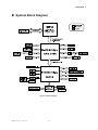
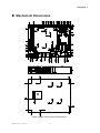
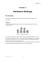
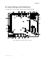
KEMF-4010 FlexATX Embedded Motherboard with AMD Athlon™ Single and Dual-Core Processors and AMD® 780E + SB710 chipset User’s Guide KEMF-4010 User’s I Contact Info: Quanmax Inc. 5F, No. 415, Ti-Ding Blvd. Sec. 2, NeiHu District, Taipei, Taiwan 114 Tel: +886-2-2799-2789 Fax: +886-2-2799-7399 Visit our site at: www.quanmax.com © 2009 Quanmax Inc. All rights reserved. The information in this user’s guide is provided for reference only. Quanmax does not assume any liability arising out of the application or use of the information or products described herein. This user’s guide may contain or reference information and products protected by copyrights or patents and does not convey any license under the patent rights of Quanmax, nor the rights of others. Quanmax is a registered trademark of Quanmax. All trademarks, registered trademarks, and trade names used in this user’s guide are the property of their respective owners. All rights reserved. This user’s guide contains information proprietary to Quanmax. Customers may reprint and use this user’s guide in other publications. Customers may alter this user’s guide and publish it only after they remove the Quanmax name, cover, and logo. Quanmax reserves the right to make changes without notice in product or component design as warranted by evolution in user needs or progress in engineering or manufacturing technology. Changes which affect the operation of the unit will be documented in the next revision of this user’s guide. Revision Date Edited by Changes 1.0 06/29/2009 SLee Initial Release 1.01 10/05/2009 SLee PCIE1,2,3 descriptions update 1.02 12/16/2009 SLee Correct RS232/422/485 pin assignment 1.1 01/29/2010 Zack Add remark on clear CMOS KEMF-4010 User’s II Content Content Content ...................................................................................................................... 3 Figures ....................................................................................................................... 5 Tables ......................................................................................................................... 6 Safety Instructions ...................................................................................................... 8 Before You Begin ...................................................................................... 8 When Working Inside a Computer ............................................................ 8 Preventing Electrostatic Discharge ........................................................... 9 Preface ..................................................................................................................... 10 How to Use This Guide........................................................................... 10 Unpacking .............................................................................................. 10 Regulatory Compliance Statements ....................................................... 10 Warranty Policy ...................................................................................... 11 Maintaining Your Computer .................................................................... 12 Chapter 1 Introduction ........................................................................................... 14 Overview ................................................................................................ 14 Product Specifications ............................................................................ 15 System Block Diagram ........................................................................... 16 Mechanical Dimensions.......................................................................... 17 Chapter 2 Hardware Settings ................................................................................ 18 Overview ................................................................................................ 18 Jumper Settings and Pin Definitions ....................................................... 19 Jumper Settings ......................................................................................... 20 Rear Panel Pin Assignments...................................................................... 22 Main Board Pin Assignments ..................................................................... 25 Chapter 3 System Installation ................................................................................ 35 0H 2 Processor Installation ............................................................................. 35 Processor Handling .................................................................................... 35 Installing the CPU ...................................................................................... 35 Removing the CPU: ................................................................................... 36 Cooler Installation ................................................................................... 37 Memory Module Installation .................................................................... 38 Installing a DIMM ....................................................................................... 39 Removing a DIMM: .................................................................................... 40 Expansive Interfaces .............................................................................. 40 KEMF-4010 User’s 3 Content Chapter 4 AMI BIOS Setup .................................................................................... 41 Overview ................................................................................................ 41 Main Menu.............................................................................................. 42 Advanced Menu ..................................................................................... 43 Boot Menu .............................................................................................. 48 Chipset Menu ......................................................................................... 48 Power Menu ........................................................................................... 50 Security Menu ........................................................................................ 51 Exit Menu ............................................................................................... 52 Chapter 5 Driver Installation .................................................................................. 53 Appendix A DIO (Digital I/O) Programming Guide .................................................... 54 Appendix B WatchDog Timer Sample Code ............................................................. 55 KEMF-4010 User’s 4 Figures Figures Figure 1 Block Diagram ............................................................................................ 16 Figure 2 KEMF-4010 Mechanical Dimensions ......................................................... 17 Figure 3 Jumper Connector...................................................................................... 18 Figure 4 KEMF-4010 Jumper and Connector Locations .......................................... 19 Figure 5 CPU alignment in Socket AM2 ................................................................... 35 Figure 6 CPU Installation ......................................................................................... 36 Figure 7 Place the CPU cooler on the retention frame ............................................. 37 Figure 8 Hook the CPU cooler clip to the mounting lug ............................................ 37 Figure 9 Lock the CPU cooler .................................................................................. 38 Figure 10 Attach the CPU fan power connector ....................................................... 38 Figure 11 DIMM Memory and 240-pin Socket .......................................................... 39 Figure 12 Memory Installation .................................................................................. 39 Figure 13 Expansive Interfaces ................................................................................ 40 5 KEMF-4010 User’s 5 Tables Tables Table 1 KEMF-4010 Specification ................................... Table 2 Jumper List ............................................. Table 3 JP1, JP2, JP3, JP6, JP7, JP13, COM Port Signal / Power Selection .... Table 4 JP4, DIO Signal / Power Selection ............................ Table 5 JP5, Parallel Port Signal Selection ............................ Table 6 JP8, ATX/AT mode Selection ................................ Table 7 JP9, Clear CMOS Selection ................................. Table 8 JP11, Panel Power Selection ................................ Table 9 JP12, Backlight Power Selection .............................. Table 10 JP14, KB / MS Signal Selection ............................. Table 11 JP15, Back Light Signal Selection ............................ Table 12 Rear Panel Connector List ................................. Table 13 AUDIO1, 3 Stack-up HD Audio Phone Jack ..................... Table 14 VGA_COM1, RS-232 / 422 / 485 Port 1 DB15+DB9 Connector ....... Table 15 LAN1,LAN2, LAN3, RJ-45 + 2 USB 2.0 Connector ................ Table 16 LAN LED Status ......................................... Table 17 PS2-KBMS1, PS/2 KB/MS Mini-DIN Connector .................. Table 18 HDMI1, HDMI Connector .................................. Table 19 Internal Connector List .................................... Table 20 ATXPWR1, 24-pin ATX Power Input Connector .................. Table 21 ATX12V1, 4-pin ATX Power Input Connector .................... Table 22 CFD1, CF Type II Connector ................................ Table 23 C0M2, COM3, COM4, COM5, COM6, RS-232 Box Header ......... Table 24 DIO1, Digital Input / Output Pin Header ........................ Table 25 HDMI_SPDIF1, SPD/IF Input / Output Pin Header ................ Table 26 CN1, Panel Backlight Wafer ................................ Table 27 AMP_L1, AMP_R1, 2 W Audio AMP Output Wafer ................ Table 28 CD1, CD-ROM Audio Input Wafer ............................ Table 29 CPU_FAN1, FAN Wafer ................................... Table 30 CHA_FAN1, CHA_FAN2, FAN Wafer .......................... Table 31 FP1, Front Panel 1 Pin Header .............................. Table 32 FP2, Front Panel 2 Pin Header .............................. Table 33 LVDS1, LVDS Panel Connector.............................. Table 34 IR1, IrDA Pin Header ..................................... KEMF-4010 User’s 6 15 20 20 20 21 21 21 21 21 22 22 22 22 23 23 23 24 24 25 25 26 26 26 27 27 27 27 27 28 28 28 28 29 29 Tables Table 35 PCI1, 32-bit / 33Mhz / 5V-key PCI Slot ........................ Table 36 PCIE1, Standard PCI Express x16 Slot ........................ Table 37 USB1, USB2, USB2.0 Pin Header ............................ Table 38 LPT1, Parallel Port DB-25 Connector ......................... Table 39 PCIE2, PCIE3, Standard PCI Express x1 Slot ................... Table 40 SATAII_1, SATAII_2, SATAII_3, SATAII_4 ,SATAII_5 ,SATAII_6 ....... Table 41 MPCIE1, Mini PCIe Connector .............................. Table 42 BIOS Main Menu ........................................ Table 43 SATA and onboard CF Device Setting Menu .................... Table 44 System Information ...................................... Table 45 Advanced Menu ......................................... Table 46 CPU Feature ........................................... Table 47 OnBoard Peripherals Configuration Settings .................... Table 48On-Chip ATA Configuration ................................. Table 49 Onboard I/O Configuration ................................. Table 50 Trusted Computing ....................................... Table 51 Hardware Health Configuration .............................. Table 52 Boot Menu ............................................. Table 53 Chipset Setting Menu ..................................... Table 54 DRAM Timing Configuration ................................ Table 55 Power Menu ........................................... Table 56 Wake Up Event Setup .................................... Table 57 Security Menu .......................................... Table 58 Exit Menu ............................................. KEMF-4010 User’s 7 29 31 32 32 33 33 34 42 42 43 43 44 45 45 46 47 47 48 48 49 50 50 51 52 Safety Instructions Safety Instructions Before You Begin Before handling the product, read the instructions and safety guidelines on the following pages to prevent damage to the product and to ensure your own personal safety. Refer to the “Advisories” section in the Preface for advisory conventions used in this user’s guide, including the distinction between Warnings, Cautions, Important Notes, and Notes. Always use caution when handling/operating a computer. Only qualified, experienced, authorized electronics service personnel should access the interior of a computer. The power supplies produce high voltages and energy hazards, which can cause bodily harm. Use extreme caution when installing or removing components. Refer to the installation instructions in this user’s guide for precautions and procedures. If you have any questions, please contact Quanmax Post-Sales Technical Support. WARNING High voltages are present inside the chassis when the unit’s power cord is plugged into an electrical outlet. Turn off system power, turn off the power supply, and then disconnect the power cord from its source before removing the chassis cover. Turning off the system power switch does not remove power to components. When Working Inside a Computer Before taking covers off a computer, perform the following steps: 1. Turn off the computer and any peripherals. 2. Disconnect the computer and peripherals from their power sources or subsystems to prevent electric shock or system board damage. This does not apply when hot swapping parts. 3. Follow the guidelines provided in “Preventing Electrostatic Discharge” on the following page. 4. Disconnect any telephone or telecommunications lines from the computer. In addition, take note of these safety guidelines when appropriate: KEMF-4010 User’s 8 Safety Instructions To help avoid possible damage to system boards, wait five seconds after turning off the computer before removing a component, removing a system board, or disconnecting a peripheral device from the computer. When you disconnect a cable, pull on its connector or on its strain-relief loop, not on the cable itself. Some cables have a connector with locking tabs. If you are disconnecting this type of cable, press in on the locking tabs before disconnecting the cable. As you pull connectors apart, keep them evenly aligned to avoid bending any connector pins. Also, before connecting a cable, make sure both connectors are correctly oriented and aligned. CAUTION Do not attempt to service the system yourself except as explained in this user’s guide. Follow installation and troubleshooting instructions closely. Preventing Electrostatic Discharge Static electricity can harm system boards. Perform service at an ESD workstation and follow proper ESD procedure to reduce the risk of damage to components. Quanmax strongly encourages you to follow proper ESD procedure, which can include wrist straps and smocks, when servicing equipment. You can also take the following steps to prevent damage from electrostatic discharge (ESD): When unpacking a static-sensitive component from its shipping carton, do not remove the component’s antistatic packing material until you are ready to install the component in a computer. Just before unwrapping the antistatic packaging, be sure you are at an ESD workstation or grounded. This will discharge any static electricity that may have built up in your body. When transporting a sensitive component, first place it in an antistatic container or packaging. Handle all sensitive components at an ESD workstation. If possible, use antistatic floor pads and workbench pads. Handle components and boards with care. Don’t touch the components or contacts on a board. Hold a board by its edges or by its metal mounting bracket. Do not handle or store system boards near strong electrostatic, electromagnetic, magnetic, or radioactive fields. KEMF-4010 User’s 9 Preface Preface How to Use This Guide This guide is designed to be used as step-by-step instructions for installation, and as a reference for operation, troubleshooting, and upgrades. NOTE Driver downloads and additional information are available under Downloads on our web site: www.quanmax.com. Unpacking When unpacking, follow these steps: 1. After opening the box, save it and the packing material for possible future shipment. 2. Remove all items from the box. If any items listed on the purchase order are missing, notify Quanmax customer service immediately. 3. Inspect the product for damage. If there is damage, notify Quanmax customer service immediately. Refer to “Warranty Policy” for the return procedure. Regulatory Compliance Statements This section provides the FCC compliance statement for Class A devices. FCC Compliance Statement for Class A Devices The product(s) described in this user’s guide has been tested and found to comply with the limits for a Class A digital device, pursuant to Part 15 of the FCC Rules. These limits are designed to provide reasonable protection against harmful interference when the equipment is operated in a commercial environment. This equipment generates, uses, and can radiate radio frequency energy and, if not installed and used in accordance with the user’s guide, may cause harmful interference to radio communications. Operation of this equipment in a residential area (domestic environment) is likely to cause harmful interference, in which case the user will be required to correct the interference (take adequate measures) at KEMF-4010 User’s 10 Preface their own expense. Changes or modifications not expressly approved by Quanmax could void the user's authority to operate the equipment. NOTE The assembler of a personal computer system may be required to test the system and/or make necessary modifications if a system is found to cause harmful interference or to be noncompliant with the appropriate standards for its intended use. Warranty Policy Limited Warranty Quanmax Inc.’s detailed Limited Warranty policy can be found under Support at www.quanmax.com. Please consult your distributor for warranty verification. The limited warranty is void if the product has been subjected to alteration, neglect, misuse, or abuse; if any repairs have been attempted by anyone other than Quanmax or its authorized agent; or if the failure is caused by accident, acts of God, or other causes beyond the control of Quanmax or the manufacturer. Neglect, misuse, and abuse shall include any installation, operation, or maintenance of the product other than in accordance with the user’s guide. No agent, dealer, distributor, service company, or other party is authorized to change, modify, or extend the terms of this Limited Warranty in any manner whatsoever. Quanmax reserves the right to make changes or improvements in any product without incurring any obligation to similarly alter products previously purchased. Return Procedure For any Limited Warranty return, please contact Support at www.quanmax.com and login to obtain a Return Material Authorization (RMA) Number. If you do not have an account, send an email to [email protected] to apply for one. All product(s) returned to Quanmax for service or credit must be accompanied by a Return Material Authorization (RMA) Number. Freight on all returned items must be prepaid by the customer who is responsible for any loss or damage caused by common carrier in transit. Returns for Warranty must include a Failure Report for each unit, by serial number(s), as well as a copy of the original invoice showing the date of purchase. To reduce risk of damage, returns of product must be in a Quanmax shipping container. If the original container has been lost or damaged, new shipping containers may be obtained from Quanmax Customer Service at a nominal cost. Quanmax owns all parts removed from repaired products. Quanmax uses new and reconditioned parts made by various manufacturers in performing warranty repairs KEMF-4010 User’s 11 Preface and building replacement products. If Quanmax repairs or replaces a product, its warranty term is not extended. Shipments not in compliance with this Limited Warranty Return Policy will not be accepted by Quanmax. Limitation of Liability In no event shall Quanmax be liable for any defect in hardware, software, loss, or inadequacy of data of any kind, or for any direct, indirect, incidental, or consequential damages in connection with or arising out of the performance or use of any product furnished hereunder. Quanmax’s liability shall in no event exceed the purchase price of the product purchased hereunder. The foregoing limitation of liability shall be equally applicable to any service provided by Quanmax or its authorized agent. Maintaining Your Computer Environmental Factors Temperature The ambient temperature within an enclosure may be greater than room ambient temperature. Installation in an enclosure should be such that the amount of air flow required for safe operation is not compromised. Consideration should be given to the maximum rated ambient temperature. Overheating can cause a variety of problems, including premature aging and failure of chips or mechanical failure of devices. If the system has been exposed to abnormally cold temperatures, allow a two-hour warm-up period to bring it up to normal operating temperature before turning it on. Failure to do so may cause damage to internal components, particularly the hard disk drive. Humidity High-humidity can cause moisture to enter and accumulate in the system. This moisture can cause corrosion of internal components and degrade such properties as electrical resistance and thermal conductivity. Extreme moisture buildup inside the system can result in electrical shorts, which can cause serious damage to the system. Buildings in which climate is controlled usually maintain an acceptable level of humidity for system equipment. However, if a system is located in an unusually humid location, a dehumidifier can be used to maintain the humidity within an acceptable range. Refer to the “Specifications” section of this user’s guide for the operating and storage humidity specifications. KEMF-4010 User’s 12 Preface Altitude Operating a system at a high altitude (low pressure) reduces the efficiency of the cooling fans to cool the system. This can cause electrical problems related to arcing and corona effects. This condition can also cause sealed components with internal pressure, such as electrolytic capacitors, to fail or perform at reduced efficiency. Power Protection The greatest threats to a system’s supply of power are power loss, power spikes, and power surges caused by electrical storms, which interrupt system operation and/or damage system components. To protect your system, always properly ground power cables and one of the following devices. Surge Protector Surge protectors are available in a variety of types and usually provide a level of protection proportional with the cost of the device. Surge protectors prevent voltage spikes from entering a system through the AC power cord. Surge protectors, however, do not offer protection against brownouts, which occur when the voltage drops more than 20 percent below the normal AC line voltage level. Line Conditioner Line conditioners go beyond the over voltage protection of surge protectors. Line conditioners keep a system’s AC power source voltage at a fairly constant level and, therefore, can handle brownouts. Because of this added protection, line conditioners cost more than surge protectors. However, line conditioners cannot protect against a complete loss of power. Uninterruptible Power Supply Uninterruptible power supply (UPS) systems offer the most complete protection against variations on power because they use battery power to keep the server running when AC power is lost. The battery is charged by the AC power while it is available, so when AC power is lost, the battery can provide power to the system for a limited amount of time, depending on the UPS system. UPS systems range in price from a few hundred dollars to several thousand dollars, with the more expensive unit s allowing you to run larger systems for a longer period of time when AC power is lost. UPS systems that provide only 5 minutes of battery power let you conduct an orderly shutdown of the system, but are not intended to provide continued operation. Surge protectors should be used with all UPS systems, and the UPS system should be Underwriters Laboratories (UL) safety approved. KEMF-4010 User’s 13 Chapter 1 Chapter 1 Introduction Overview The KEMF-4010 is a FlexATX embedded motherboard that built with the fastest onboard graphics - AMD® 780E and supporting AMD Athlon™ X2 dual-core processor and DDR2 DIMM up to 8GB. This embedded board offers the latest video performance and I/O interfaces at an extremely attractive price/performance ratio and measures 229 x 191mm, a 42 percent space reduction over ATX boards. The KEMF-4010 features HDMI, 18/24-bit dual channel LVDS panel support, SATA 3 Gb/s, RS-232/422/485 serial port, DI/DO, Gigabit Ethernet, USB 2.0, keyboard/mouse, and HD audio. Mini-PCIe, PCIe x1, PCIe x16 and PCI support provides expansion capability for your diversify applications. Checklist 2x SATA cable 1x Driver/ Manual CD 1x Quick Installation Guide 1x KEMF-4010 motherboard 1x Shield I/O Features Supports AMD Athlon™ X2 Dual-Core Processor Integrated ATI Radeon™ HD 3200 graphics Dual Channel DDR2 DIMM 400/533/667/800MHz, up to 8 GB 3x GbE, 10x USB 2.0, 6x SATA 3Gb/s, CF Type II, HD Audio 1x PCIe x16 slot, 2x PCIe x1 slots, 1x Mini PCIe slot, 1x PCI slot Hardware Monitor, Watchdog Timer KEMF-4010 User’s 14 Chapter 1 Product Specifications CPU Support AMD Athlon™ Single and Dual-Core Processors Chipset AMD780E + SB710 Memory 2x DDR2 400/533/667/800 DIMM Socket, up to 8GB BIOS AMI PnP 8MbFlash Display Integrated ATI Radeon™ HD 3200 graphics Dual Independent Display Support Single/ Dual channel 18/24 bit LVDS, with a optional LVDS to DVI-D cable 1x HDMI 1x VGA LAN 3x RJ-45, Gigabit Ethernet (Realtek 8111C) Audio Peripheral Support Realtek HD audio codec onboard 2W Amplifier support One audio stack connector for Audio-Out, Audio-In and Mic-In One wafer connector for CD-In One 1x4 pin 2.54mm pitch header for S/PDIF 1x CompactFlash socket 6x SATA 3Gb/s (RAID 0/1/10 support) 10x USB 2.0 6x COMs with Power Selection (1x RS232/422/485, 5x RS-232) 1x IrDA support from remote control via COM5 4x DI/DOs with Power Selection 1x PS/2 Keyboard connector 1x PS/2 Mouse connector 1x Parallel port TPM TPM 1.2 Power ATX-24P + ATX-4P AT/ATX support Expansion Watchdog Timer Hardware Monitor Dimensions Environmental Factors Certifications 1x PCI slot 2x PCIe x1 slots 1x PCIe x16 slot 1x Mini PCIe socket 1-255 step, can be set with software on Super I/O Operating voltage and power failure CPU and system temperature CPU and system fan speed FlexATX (229 x 191 mm) Operation Temp: 0ºC - 60ºC Storage Temp.: -10ºC - 85ºC Humidity: 0% - 90% CE, FCC Class A Table 1 KEMF-4010 Specification KEMF-4010 User’s 15 Chapter 1 System Block Diagram Figure 1 Block Diagram KEMF-4010 User’s 16 Chapter 1 Mechanical Dimensions Figure 2 KEMF-4010 Mechanical Dimensions KEMF-4010 User’s 17 Chapter 2 Chapter 2 Hardware Settings Overview This chapter provides the definitions and locations of jumpers, headers, and connectors. Jumpers The product has several jumpers which must be properly configured to ensure correct operation. Figure 3 Jumper Connector For a three-pin jumper (see Figure 3), the jumper setting is designated “1-2” when the jumper connects pins 1 and 2. The jumper setting is designated “2-3” when pins 2 and 3 are connected and so on. You will see that one of the lines surrounding a jumper pin is thick, which indicates pin No.1. To move a jumper from one position to another, use needle-nose pliers or tweezers to pull the pin cap off the pins and move it to the desired position. KEMF-4010 User’s 18 Chapter 2 Jumper Settings and Pin Definitions For jumper and connector locations, please refer to the diagrams below. Figure 4 KEMF-4010 Jumper and Connector Locations KEMF-4010 User’s 19 Chapter 2 Jumper Settings To ensure correct system configuration, the following section describes how to set the jumpers to enable/disable or change functions. For jumper descriptions, please refer to the table below. Label JP1 JP2 JP3 JP4 JP5 JP6 JP7 JP8 JP9 JP11 JP12 JP13 JP14 JP15 Table 2 Jumper List Function COM6 Signal / Power Selection COM4 Signal / Power Selection COM2 Signal / Power Selection DIO Signal / Power Selection Parallel Port Signal Selection COM5 Signal / Power Selection COM3 Signal / Power Selection ATX/AT mode Selection Clear CMOS Selection Panel Power Selection Backlight Power Selection COM1 Signal / Power Selection KB / MS Signal Selection BL Signal Selection Table 3 JP1, JP2, JP3, JP6, JP7, JP13, COM Port Signal / Power Selection Jumper Setting Function 1-3 Short Pin 1 = +12V 3-5 Short Pin 1 = +5V 1 5-7 Short Pin 1 = +5V Pin 1 = DCD@RS232, TX-@RS422, 7-9 Short DATA-@RS485 (Default) 2-4 Short Pin 9 = +12V 4-6 Short Pin 9 = +5V 2 6-8 Short Pin 9 = +5V 8-10 Short Pin 9 = RI (Default) JP1,JP2,JP3,JP6,JP7 : Pitch: 2.54mm NY 6T[YIMTEX 3362*05SANGR] JP13: Pitch: 2.54mm [YIMTEX 3322*05SAGR(6T] Cable : 0C501P040926000L COM Port cable, 10-pin 2.54mm to DB-9 connector with bracket, L=26cm Table 4 JP4, DIO Signal / Power Selection Jumper Status 1-2 +5V(Default) 2-3 +12V Pitch: 2.54mm [YIMTEX 3321*03SAGR(6T)] KEMF-4010 User’s 20 Chapter 2 Table 5 JP5, Parallel Port Signal Selection Jumper 1 2 3 Setting Function 1-2 Short Pin 4 of LPT1 = ERR# (Default) 1-3 Short Pin 4 of LPT1 = +5V 4-6 Short Pin 6 of LPT1 = +5V 5-6 Short Pin 6 of LPT1 = INIT# (Default) 7-8 Short Pin 8 of LPT1 = SLIN# (Default) 7-9 Short Pin 8 of LPT1 = +5V Pitch:2.54mm NY 6T[YIMTEX 3362*05SANGR] Table 6 JP8, ATX/AT mode Selection Jumper Status Open ATX mode(Default) Short AT mode Pitch: 2.0mm [YIMTEX 3291*02SAGR(6T)] Table 7 JP9, Clear CMOS Selection Jumper Status 1-2 Normal Operation (Default) 2-3 Clear CMOS Pitch: 2.0mm [YIMTEX 3291*03SAGR(6T)] Remark: You must go to BIOS EXIT menu to do “Load Optimal Defaults” after clear CMOS. Table 8 JP11, Panel Power Selection Jumper Status 1-2 +3.3V(Default) 2-3 +5V Pitch: 2.54mm [YIMTEX 3321*03SAGR(6T)] Note: If DVI cable is connecting to LVDS panel connector, the Pin2-3 should be shorted. Table 9 JP12, Backlight Power Selection Jumper Status 1-2 +12V(Default) 2-3 +5V Pitch: 2.54mm [YIMTEX 3321*03SAGR(6T)] KEMF-4010 User’s 21 Chapter 2 Table 10 JP14, KB / MS Signal Selection Pin 1 3 5 7 9 3-5 4-6 Short Signal Name +5V KBCLK from SIO KBCLK to PS2-KBMS1 MSCLK from SIO MSCLK to PS2-KBMS1 PS/2 Keyboard on PS2-KBMS1 is Enabled Pin 2 4 6 8 10 7-9 8-10 Short Signal Name GND KBDAT from SIO KBDAT to PS2-KBMS1 MSDAT from SIO MSDAT to PS2-KBMS1 PS/2 Mouse on PS2-KBMS1 is Enabled Pitch: 2.54mm [YIMTEX 3322*05SAGR(6T] Table 11 JP15, Back Light Signal Selection Jumper Status 1-2 High Active(Default) 2-3 Low Active Pitch: 2.0mm [YIMTEX 3291*03SAGR(6T)] Rear Panel Pin Assignments Table 12 Rear Panel Connector List Label AUDIO1 VGA_COM1 LAN1 LAN2 LAN3 PS2-KBMS1 HDMI1 Function 3 Stack-up HD Audio Phone Jack RS-232 / 422 / 485 Port 1 DB9+DB15 Connector LAN1 & USB2.0 Port 0,1 Connector LAN2 & USB2.0 Port 2,3 Connector LAN2 & USB2.0 Port 4,5 Connector PS/2 KB/MS Mini-DIN Connector HDMI Connector Table 13 AUDIO1, 3 Stack-up HD Audio Phone Jack Signal Name BLUE LINE IN GREEN LINE OUT PINK MIC IN [Foxconn JA33331-H11P-4F] *Support Jack re-tasking & multi-streaming KEMF-4010 User’s 22 Chapter 2 Table 14 VGA_COM1, RS-232 / 422 / 485 Port 1 DB15+DB9 Connector Pin V1 V3 V5 V7 V9 V11 V13 V15 C1 C3 C5 C7 C9 Signal Name Red Blue GND GND +5V NC HSYNC DDC clock RS-232:DCD, Data carrier detect RS-422:TXRS-485:DATARS-232:TXD, Transmit data RS-422:TX+ RS-485:DATA+ GND, ground RTS, Request to send RI, Ring indicator Pin V2 V4 V6 V8 V10 V12 V14 Signal Name Green NC GND GND GND DDC data VSYNC C2 RS-232:RXD, Receive data RS-422:RX+ RS-485:N/A RS-232:DTR, Data terminal ready RS-422:RXRS-485:N/A DSR, Data set ready CTS, Clear to send NC C4 C6 C8 C10 [芬瑩 D201B1N01002N] Note:COM 1 RS-232 / 422 / 485 can be selected in BIOS setup. Note:RS-485 is half-duplex mode. Table 15 LAN1,LAN2, LAN3, RJ-45 + 2 USB 2.0 Connector Pin L1 L2 L3 L4 L5 L6 L7 L8 L9 L10 L11 Signal VCC MDI[0]+ MDI[0]MDI[1]+ MDI[1]MDI[2]+ MDI[2]MDI[3]+ MDI[3]GND YLED- Pin L12 L13 L14 U1 U2 U3 U4 U5 U6 U7 U8 Signal YLED+ GLEDGLED+ +5VSV USB_AUSB_A+ GND +5VSB USB_BUSB_B+ GND [UDE RU1-161F9WGF(XB)] Table 16 LAN LED Status Status No link 10M link 10M active 100M link 100M active 1000M link 1000M active KEMF-4010 User’s Led Orange / Green Off Off Off Green on Green on Orange on Orange on 23 Yellow Off Off Blink Off Blink Off Blink Chapter 2 Table 17 PS2-KBMS1, PS/2 KB/MS Mini-DIN Connector Pin Signal Function 1 KBDAT Keyboard Data 2 NC No Connect 3 GND Ground 4 KB5V +5VSB Power Source 5 KBCLK Keyboard Clock 6 NC No Connect 7 MSDAT Mouse Data 8 NC No Connect 9 GND Ground 10 KB5V +5VSB Power Source 11 MSCLK Mouse Clock 12 NC No Connect MINI DIN DIP 6/6P MH11061-P36-4F 90D(F) [FOXCONN] Table 18 HDMI1, HDMI Connector Pin 1 2 3 4 5 6 7 8 9 10 11 12 13 14 15 16 17 18 19 Signal TMDS Data2+ TMDS Data2 Shield TMDS Data2– TMDS Data1+ TMDS Data1 Shield TMDS Data1– TMDS Data0+ TMDS Data0 Shield TMDS Data0– TMDS Clock+ TMDS Clock Shield TMDS Clock– CEC Reserved SCL SDA DDC/CEC Ground +5 V Power Hot Plug Detect [KUON YI HDMI-KRPS00-A03N2-L] *:BIOS Auto detect HDMI or PCIE mode ** Note: When HDMI is occupied, the PCIe x16 slot will support PCIe x8 only. ** KEMF-4010 User’s 24 Chapter 2 Main Board Pin Assignments Table 19 Internal Connector List Label Function Label Function ATXPWR1 24-pin ATX Power Input Connector FP1 Front Panel 1 Pin Header ATX12V1 4-pin ATX Power Input Connector FP2 Front Panel 2 Pin Header CFD1 CF Type II Connector LVDS1 LVDS Panel Connector COM2 RS-232 Port 2 Box Header PCI1 32-bit / 33Mhz / 5V-key PCI Slot COM3 RS-232 Port 3 Box Header PCIE1 Standard PCI Express x16 Slot COM4 RS-232 Port 4 Box Header PCIE2 Standard PCI Express x1 Slot COM5 RS-232 Port 5 Box Header PCIE3 Standard PCI Express x1 Slot COM6 RS-232 Port 6 Box Header SATAII_1 Primary Serial ATA Connector DIO1 Digital Input / Output Pin Header SATAII_2 Serial ATA Connector HDMI_SPDIF1 SPD/IF Output Pin Header SATAII_3 Serial ATA Connector CN1 Panel Backlight Wafer SATAII_4 Serial ATA Connector AMP_L1 Left Channel 2W Audio AMP Output Wafer SATAII_5 Serial ATA Connector AMP_R1 Right Channel 2W Audio AMP Output Wafer SATAII_6 Serial ATA Connector CD1 CD-ROM Audio Input Wafer USB1 USB2.0 Port 6, 7 Pin Header DDRII_1 Primary DDR2 Memory DIMM Slot USB2 USB2.0 Port 8, 9 Pin Header DDRII_2 Secondary DDR2 Memory DIMM Slot LPT1 Parallel Port Pin Header CPU_FAN1 CPU FAN Wafer MPCIE1 Mini PCIe Connector CHA_FAN1 System FAN Wafer IR1 IrDA Pin Header CHA_FAN2 System FAN Wafer Table 20 ATXPWR1, 24-pin ATX Power Input Connector Pin 1 2 3 4 5 6 7 8 9 10 11 12 Signal +3.3V +3.3V GND +5V GND +5V GND POWER OK +5VSB +12V +12V +3.3V Pin 13 14 15 16 17 18 19 20 21 22 23 24 DIP 12P*2.180D(M) [YIMTEX 576MWA2*12STR] KEMF-4010 User’s 25 Signal +3.3V -12V GND PS_ON GND GND GND -5V +5V +5V +5V GND Chapter 2 Table 21 ATX12V1, 4-pin ATX Power Input Connector Pin 1 3 Signal GND +12V Pin 2 4 Signal GND +12V Pitch:4.2mm 空心 PIN [YIMTEX 576MWA2*02STR] Table 22 CFD1, CF Type II Connector (This Connector is at backside of board.) Signal Name GND IDE Data 3 IDE Data 4 IDE Data 5 IDE Data 6 IDE Data 7 IDE Chip select 1# GND GND GND GND GND +5V GND GND GND GND SDA2 IDE Address 1 IDE Address 0 IDE Data 0 IDE Data 1 IDE Data 2 IOIS16# GND Pin 1 2 3 4 5 6 7 8 9 10 11 12 13 14 15 16 17 18 19 20 21 22 23 24 25 Pin 26 27 28 29 30 31 32 33 34 35 36 37 38 39 40 41 42 43 44 45 46 47 48 49 50 Signal Name GND IDE Data 11 IDE Data 12 IDE Data 13 IDE Data 14 IDE Data 15 IDE Chip select 3# GND IDEIOR# IDEIOW# +5V IDEIRQ +5V PCSEL NC Reset IDE IDEIORDY DREQ DACK# IDE activity PDIAG# IDE Data 8 IDE Data 9 IDE Data 10 GND [晉祥 CF1A-71041-00E01] Table 23 C0M2, COM3, COM4, COM5, COM6, RS-232 Box Header Pin 1 2 3 4 5 6 7 8 9 10 Signal DCD, Data carrier detect RXD, Receive data TXD, Transmit data DTR, Data terminal ready GND, ground DSR, Data set ready RTS, Request to send CTS, Clear to send RI, Ring indicator NC Pitch: 2.54mm [YIMTEX 32510SAG1R(6T)] KEMF-4010 User’s 26 Chapter 2 Table 24 DIO1, Digital Input / Output Pin Header Pin 1 3 5 7 9 Signal Digital Output 0 Digital Output 1 Digital Output 2 Digital Output 3 +5V / +12V * Pin 2 4 6 8 10 Signal Digital Input 0 Digital Input 1 Digital Input 2 Digital Input 3 GND Pitch:2.54mm [YIMTEX 3322*05SAGR(6T] *:The voltage is selected by JP4 Table 25 HDMI_SPDIF1, SPD/IF Input / Output Pin Header Pin 1 2 3 4 Signal Name +5V GND SPD/IF Output GND Pitch: 2.54mm [YIMTEX 3321*04SAGR(6T)] Table 26 CN1, Panel Backlight Wafer Pin 1 2 3 4 5 6 7 Signal Name BL_EN* GND +5V / +12V ** +5V / +12V ** GND BL_ADJ NC Pitch: 1.25mm WAFER [YIMTEX 501MW1*7STR] *:The voltage is selected by JP15, **:The voltage is selected by JP12 Note:BL_ADJ can be setting from 0V to 5V in BIOS setup. Table 27 AMP_L1, AMP_R1, 2 W Audio AMP Output Wafer Pin 1 2 Signal Name Speaker+ Speaker- Pitch=2.0mm WAFER [YIMTEX 503PW1*02STR] Table 28 CD1, CD-ROM Audio Input Wafer Pin 1 2 3 4 Signal Name CD-IN-R GND GND CD-IN-L P-2.54mm WAFER [YIMTEX 522CW4SGR] KEMF-4010 User’s 27 Chapter 2 Table 29 CPU_FAN1, FAN Wafer Pin Signal 1 GND 2 +12V 3 FAN_RPM 4 FAN_RPM_CTL Pitch: 2.54mm WAFER [FOXCONN HF2704E-M1] * Support CPU smart Fan Function Table 30 CHA_FAN1, CHA_FAN2, FAN Wafer Pin Signal 1 GND 2 +12V 3 FAN_RPM Pitch: 2.54mm WAFER [YIMTEX 521AW1*03STR] Table 31 FP1, Front Panel 1 Pin Header Pin Signal Pin Signal 1 Reset Button + 2 Speaker + 3 Reset Button - 4 NC 5 HDD LED + 6 Internal Speaker- 7 HDD LED - 8 Speaker - Pitch: 2.54mm [YIMTEX 3322*04SAGR(6T)] Note:Internal Buzzer is enabled when Pin6-8 is shorted. Table 32 FP2, Front Panel 2 Pin Header Pin Signal Pin Signal 1 Power LED + 2 Power Button + 3 NC 4 Power Button - 5 Power LED - 6 NC 7 Keyboard Lock 8 SMBus Data 9 GND 10 SMBus Clock Pitch: 2.54mm [YIMTEX 3322*05SAGR(6T] KEMF-4010 User’s 28 Chapter 2 Table 33 LVDS1, LVDS Panel Connector Signal Name Pin Pin Signal Name NC 2 1 NC +3.3V / +5V* 4 3 +3.3V / +5V* TxclkB- 6 5 TxclkA- TxclkB+ 8 7 TxclkA+ GND 10 9 GND TxoutB0- 12 11 TxoutA0- TxoutB0+ 14 13 TxoutA0+ TxoutB1- 16 15 TxoutA1- TxoutB1+ 18 17 TxoutA1+ TxoutB2- 20 19 TxoutA2- TxoutB2+ 22 21 TxoutA2+ TxoutB3- 24 23 TxoutA3- TxoutB3+ 26 25 TxoutA3+ GND 28 27 GND I2C_Clock 30 29 I2C_Data Pitch: 1.25mm Tin Plated [HIROSE DF13-30DP-1.25(24)] Cable: 0C5029003000070L LVDS Port cable, 30-pin 1.25mm to DVI connector with bracket, L=30cm * The voltage is selected by JP11 Note: If DVI cable is connecting to LVDS panel connector, the JP11 Pin2-3 should be shorted. Table 34 IR1, IrDA Pin Header Pin 1 2 3 4 5 Signal Name +5V Key RXD GND TXD Pitch: 2.54mm [YIMTEX 3321*05SAGR-02] Table 35 PCI1, 32-bit / 33Mhz / 5V-key PCI Slot Pin 1 2 3 4 5 6 7 8 9 10 KEMF-4010 User’s Side B -12V Reserved Ground Reserved +5V +5V INTB# INTD# Reserved REQ1# * 29 Side A Reserved +12V Reserved Reserved +5V INTA# INTC# +5V GNT1# * +5V Chapter 2 11 12 13 14 15 16 17 18 19 20 21 22 23 24 25 26 27 28 29 30 31 32 33 34 35 36 37 38 39 40 41 42 43 44 45 46 47 48 49 50 51 52 53 54 55 56 57 58 59 60 61 62 Reserved Ground Ground CLK1 * Ground CLK0 Ground REQ0# +5V AD[31] AD[29] Ground AD[27] AD[25] +3.3V C/BE[3]# AD[23] Ground AD[21] AD[19] +3.3V AD[17] C/BE[2]# Ground IRDY# +3.3V DEVSEL# Ground LOCK# PERR# +3.3V SERR# +3.3V C/BE[1]# AD[14] Ground AD[12] AD[10] Ground IDSEL1 * Ground Ground +3.3VAUX RST# +5V GNT0# Ground PME# AD[30] +3.3V AD[28] AD[26] Ground AD[24] IDSEL0 +3.3V AD[22] AD[20] Ground AD[18] AD[16] +3.3V FRAME# Ground TRDY# Ground STOP# +3.3V SMB_CLK SMB_DAT Ground PAR AD[15] +3.3V AD[13] AD[11] Ground AD[09] KEY AD[08] AD[07] +3.3V AD[05] AD[03] Ground AD[01] +5V Reserved +5V +5V C/BE[0]# +3.3V AD[06] AD[04] Ground AD[02] AD[00] +5V Reserved +5V +5V PCI 60*2P 180D (F) [FOXCONN EH06001-DAW-DF] *:Reserved for second PCI master device. KEMF-4010 User’s 30 Chapter 2 Table 36 PCIE1, Standard PCI Express x16 Slot Pin 1 2 3 4 5 6 7 8 9 10 11 12 13 14 15 16 17 18 19 20 21 22 23 24 25 26 27 28 29 30 31 32 33 34 35 36 37 38 39 40 41 42 43 44 45 46 47 48 49 50 51 52 53 54 55 56 57 58 59 60 61 KEMF-4010 User’s Side B +12V +12V +12V Ground SMCLK SMDAT Ground +3.3V JTAG1 +3VSB WAKE# Reserved Ground HSOP0 HSON0 Ground PRSNT#1 Ground HSOP1 HSON1 Ground Ground HSOP2 HSON2 Ground Ground HSOP3 HSON3 Ground Reserved PRSNT#2 Ground HSOP4 HSON4 Ground Ground HSOP5 HSON5 Ground Ground HSOP6 HSON6 Ground Ground HSOP7 HSON7 Ground PRSNT#3 Ground HSOP8 HSON8 Ground Ground HSOP9 HSON9 Ground Ground HSOP10 HSON10 Ground Ground 31 Side A PRSNT#(B) +12V +12V Ground JTAG2 JTAG3 JTAG4 JTAG5 +3.3V +3.3V PWRGD Ground REFCLK+ REFCLKGround HSIP0 HSIP0 Ground Reserved Ground HSIP1 HSIP1 Ground Ground HSIP2 HSIP2 Ground Ground HSIP3 HSIP3 Ground Reserved Reserved Ground HSIP4 HSIP4 Ground Ground HSIP5 HSIP5 Ground Ground HSIP6 HSIP6 Ground Ground HSIP7 HSIP7 Ground Reserved Ground HSIP8 HSIP8 Ground Ground HSIP9 HSIP9 Ground Ground HSIP10 HSIP10 Chapter 2 62 63 64 65 66 67 68 69 70 71 72 73 74 75 76 77 78 79 80 81 82 HSOP11 HSON11 Ground Ground HSOP12 HSON12 Ground Ground HSOP13 HSON13 Ground Ground HSOP14 HSON14 Ground Ground HSOP15 HSON15 Ground PRSNT#4 Reserved Ground Ground HSIP11 HSIP11 Ground Ground HSIP12 HSIP12 Ground Ground HSIP13 HSIP13 Ground Ground HSIP14 HSIP14 Ground Ground HSIP15 HSIP15 Ground WPCS-164AN1B22UWL [WIN WIN] ** Note: When HDMI is occupied, the PCIe x16 slot will support PCIe x8 only. ** Table 37 USB1, USB2, USB2.0 Pin Header Pin 1 3 5 7 9 Signal Name +5V USB_AUSB_A+ GND KEY Pin 2 4 6 8 10 Signal Name +5V USB_BUSB_B+ GND GND Pitch: 2.54mm [YIMTEX 3322*05SAGR(6T) -09] Cable 0C502USB0201010L USB cable, 2.54mm 10-pin to 2xUSB connectors with bracket, L=30cm Table 38 LPT1, Parallel Port DB-25 Connector Signal Line printer strobe PD0, parallel data 0 PD1, parallel data 1 PD2, parallel data 2 PD3, parallel data 3 PD4, parallel data 4 PD5, parallel data 5 PD6, parallel data 6 PD7, parallel data 7 ACK, acknowledge Busy Paper empty Select Pin 1 3 5 7 9 11 13 15 17 19 21 23 25 Pin 2 4 6 8 10 12 14 16 18 20 22 24 26 Signal AutoFeed Error Initialize Select In Ground Ground Ground Ground Ground Ground Ground Ground NA Pitch:2.0mm NY 6T [YIMTEX 32626MAGR] Cable 0C501P042526000L CABLE, FLAT DB25P MALE/IDC 26P 2.0mm 26CM W/BRACKET KEMF-4010 User’s 32 Chapter 2 Table 39 PCIE2, PCIE3, Standard PCI Express x1 Slot Pin 1 2 3 4 5 6 7 8 9 10 11 12 13 14 15 16 17 18 Side B +12V +12V +3.3VAUX WAKE# RST# Ground PETp0 PETn0 Ground PETp1 PETn1 SMB_CLK Ground NC NC Ground NC NC Side A +3.3V +3.3V Ground REFCLK+ REFCLKGround PERp0 PERn0 Ground PERp1 PERn1 SMB_DAT Ground NC NC Ground NC NC WPES-036AN3B22UWS [TECHBEST] Table 40 SATAII_1, SATAII_2, SATAII_3, SATAII_4 ,SATAII_5 ,SATAII_6 Serial ATA Connector Pin 1 2 3 4 5 6 7 Signal Name GND TX+ TXGND RXRX+ GND [FOXCONN LD1807V-S52U] Cable 0C501ATA0746000L SATA cable, 7-pin connector with lock, L=46cm ** Note: SATAII_5, SATAII_6 can not support AHCI & Raid Function** NOTE 1. 2. A RAID 0 or RAID 1 configuration requires at least two hard drives. If more than two hard drives are to be used, the total number of hard drives must be an even number. A RAID 10 configuration requires at least four hard drives and the total number of hard drives must be an even number. KEMF-4010 User’s 33 Chapter 2 Table 41 MPCIE1, Mini PCIe Connector Signal WAKE# Reserved Reserved CLKEQ# Ground REFCLKREFCLK+ Ground Reserved Reserved Ground PERn0 PERp0 Ground Ground PETn0 PETp0 Ground Reserved Reserved Reserved Reserved Reserved Reserved Reserved Reserved Pin 1 3 5 7 9 11 13 15 17 19 21 23 25 27 29 31 33 35 37 39 41 43 45 47 49 51 [FOXCONN AS0B226-S56N-7F] KEMF-4010 User’s 34 Pin 2 4 6 8 10 12 14 16 18 20 22 24 26 28 30 32 34 36 38 40 42 44 46 48 50 52 Signal +3.3V Ground +1.5V UIM_PWR UIM_DATA UIM_CLK UIM_RESET UIM_VPP Ground W_disable# PERST# +3VSB Ground +1.5V SMB_CLK SMB_DATA Ground USB_DUSB_D+ Ground LED_WWAN# LED_WAN# LED_WPAN# +1.5V Ground +3.3V Chapter 3 Chapter 3 System Installation Processor Installation Processor Handling Carefully follow the steps below in order to prepare the CPU for installation: 1. Remove processor from packaging. 2. Handle the CPU by grasping the substrate edges only with thumb and forefinger. CAUTION Do not touch processor contacts to prevent damaging the CPU. Installing the CPU Carefully follow the steps below in order to install the CPU: 1. Check and confirm that you are installing the correct CPU type. 2. Completely lift up the CPU socket locking lever. 3. Align the gold triangle on the CPU with the similar marking on the socket (see figure below). Figure 5 CPU alignment in Socket AM2 KEMF-4010 User’s 35 Chapter 3 4. Make sure that the CPU pins fit perfectly into their holes. Once the CPU is positioned into its socket, place one finger down on the middle of the CPU, lowering the locking lever and latching it into the fully locked position. Figure 6 CPU Installation NOTE You should not have to press down on the processor. If the processor does not drop completely into the socket, adjust the CPU orientation until the processor drops completely in. Removing the CPU: To remove the CPU, reverse the installation steps. 1. Before removing the CPU, turn off the system power and wait for about 20 minutes until the heat radiation plate of the cooling fan and the CPU cools down. 2. To remove the CPU, follow Step 2 of Installing the CPU above. 3. Remove the CPU by grasping the substrate edges only with thumb and forefinger and lifting it out with a purely vertical motion. WARNING The CPU and the heat-sink may be hot and could cause burns. KEMF-4010 User’s 36 Chapter 3 Cooler Installation The system must not be operated without a cooler (heat sink and fan) to provide the necessarily cooling. Install the cooling unit supplied as follows: CAUTION Make sure that good thermal contact is made between the processor and heat sink. Insufficient contact or incorrect use of heat sink, fan, or thermal compound can cause the processor to overheat, which may crash the system or cause permanent damage to the CPU. 1. 2. 3. Install the correct CPU as described above. Apply an even and thin layer of thermal grease on the surface of the installed CPU. Place the CPU cooler on the retention frame. Figure 7 Place the CPU cooler on the retention frame 4. Hook the CPU cooler clip to the mounting lug on one side of the retention frame. On the other side, push straight own on the CPU cooler clip to hook it to the mounting lug on the retention frame. Figure 8 Hook the CPU cooler clip to the mounting lug KEMF-4010 User’s 37 Chapter 3 5. Turn the cam handle from the left side to the right side to lock into place. (Refer to your CPU cooler installation manual for instructions on installing the cooler.) Figure 9 Lock the CPU cooler 6. Attach the power connector of the CPU cooler to the CPU fan header on the motherboard. Figure 10 Attach the CPU fan power connector CAUTION Use extreme care when removing the CPU cooler because the thermal grease/tape between the CPU cooler and CPU may adhere to the CPU. Inadequately removing the CPU cooler may damage the CPU. Memory Module Installation Figure below displays the notch marks as they should look on your DIMM memory modules. DDR2 DIMMs have 240-pins and one notch that will match with the onboard DIMM sockets. DIMM modules are installed by placing the chip firmly into the socket at a 90-degree angle and pressing straight down until it fits tightly into the DIMM socket. KEMF-4010 User’s 38 Chapter 3 Figure 11 DIMM Memory and 240-pin Socket Installing a DIMM Carefully follow the steps below in order to install the DIMMs: To avoid generating static electricity and damaging the DIMM, ground yourself by touching a grounded metal surface or using a ground strap before you touch the DIMM. 1. Do not touch the connectors of the DIMM. Dirt or other residue may cause a malfunction. 2. Hold the DIMM with its notch aligned with the memory socket of the KEMF-4010 and insert it completely into the socket. Lift the locking tabs at each end of the DIMM socket to lock it in position. 3. If you install two DIMMs, install the second DIMM using the same procedure as above. 4. If the DIMM does not go in smoothly, do not force it. Pull it all the way out and try again. 5. Make sure the DIMM is properly installed and locked by the tabs on both sides of the socket. Figure 12 Memory Installation KEMF-4010 User’s 39 Chapter 3 Removing a DIMM: To remove the DIMM, use your fingers or a small screwdriver to carefully push away the plastic tabs that secure the DIMM at each end. Lift it out of the socket. NOTE Make sure you store the DIMM in an anti-static bag. The socket must be populated with memory modules of the same size and manufacturer. Expansive Interfaces The board comes with one PCIex16 slot, two PCIex1 slot, one PCI slot, one Mini-PCIe and Compact Flash Type II interfaces. 1x PCIe x16 slot ** When HDMI is occupied, this slot will support PCIe x8 only. ** 2x PCIe x1 slots 1x PCI slot 1x Mini PCIe socket CF Type II Connector (on the back side of board) Figure 13 Expansive Interfaces NOTE When adding or removing expansion cards, make sure that you unplug the power supply first. Meanwhile, read the documentation for the expansion card to configure any necessary hardware or software settings for the expansion card, such as jumpers, switches or BIOS configuration. KEMF-4010 User’s 40 Chapter 4 Chapter 4 AMI BIOS Setup Overview This chapter provides a description of the AMI BIOS. The BIOS setup menus and available selections may vary from those of your product. For specific information on the BIOS for your product, please contact Quanmax. NOTE The BIOS menus and selections for your product may vary from those in this chapter. For the BIOS manual specific to your product, please contact Quanmax. AMI's ROM BIOS provides a built-in Setup program, which allows the user to modify the basic system configuration and hardware parameters. The modified data will be stored in a battery-backed CMOS, so that data will be retained even when the power is turned off. In general, the information saved in the CMOS RAM will not need to be changed unless there is a configuration change in the system, such as a hard drive replacement or when a device is added. It is possible for the CMOS battery to fail, which will cause data loss in the CMOS only. If this happens you will need to reconfigure your BIOS settings. KEMF-4010 User’s 41 Chapter 4 Main Menu The BIOS Setup is accessed by pressing the DEL key after the Power-On Self-Test (POST) memory test begins and before the operating system boot begins. Once you enter the BIOS Setup Utility, the Main Menu will appear on the screen. The Main Menu provides System Overview information and allows you to set the System Time and Date. Use the “<” and “>” cursor keys to navigate between menu screens. Table 42 BIOS Main Menu BIOS SETUP UTILITY Main Advanced System Date System Time Boot Chipset Power Exit Use [ENTER], [TAB] or [SHIFT-TAB] to select a field. Mon 06/28/2009] [10:18:15] :[Not Detected] :[Not Detected] :[Not Detected] :[Not Detected] :[Not Detected] :[Not Detected] :[SanDisk SDCFB-32] > SATA1 > SATA2 > SATA3 > SATA4 > SATA5 > SATA6 > CF Security Use [+] or [-] to configure system Time. <> Select Screen ↑↓ Select Item +- Change Field Tab Select Field F1 General Help F10 Save and Exit ESC Exit > System Information V02.61 (C)Copyright 1985-2006, American Megatrends, Inc. Below table is described for SATA1-6 and onboard CF setting. Table 43 SATA and onboard CF Device Setting Menu BIOS SETUP UTILITY Main Advanced SATA1 Device Boot Chipset Power Security Exit Select the type of device :Not Detected connected to the system. LBA/ Large Mode DMA Mode S.M.A.R.T [Auto] [Auto] [Auto] <> Select Screen ↑↓ Select Item +- Change Field Tab Select Field F1 General Help F10 Save and Exit ESC Exit V02.61 (C)Copyright 1985-2006, American Megatrends, Inc. LBA/ Large Mode [Auto] Enables or disables the LBA (Logical Block Addressing)/ Large mode. Setting to Auto enables the LBA mode if the device supports this mode, and if the device was KEMF-4010 User’s 42 Chapter 4 not previously formatted with LBA mode disabled. Options: Disabled, Auto DMA Mode [Auto] Setup DMA Mode. S.M.A.R.T [Auto] SMART stands for Smart Monitoring, Analysis, and Reporting Technology. It allows AMIBIOS to use the SMART protocol to report server system information over a network. Options: Auto, Disabled, Enabled Table 44 System Information BIOS SETUP UTILITY Main Advanced AMIBIOS Version Build Date: Boot Chipset Power Security Exit : 1.11 :06/25/09 <> Select Screen ↑↓ Select Item +- Change Field Tab Select Field F1 General Help F10 Save and Exit ESC Exit Processor AMD Athlon (TM) 64 Processor 3100+ Speed :2000 MHz System Memory Size :3328MB V02.61 (C)Copyright 1985-2006, American Megatrends, Inc. Advanced Menu Table 45 Advanced Menu BIOS SETUP UTILITY Main Advanced Boot Chipset Power Security Exit Advanced Settings Quick Boot [Enabled] Full Screen LOGO Display [Disabled] Bootup Num-Lock [ON] Wait For ’F1’ If Error [Enabled] > CPU Feature > OnBoard Peripherals Configuration > Trusted Computing > Hardware Health Configuration <> Select Screen ↑↓ Select Item +- Change Field Tab Select Field F1 General Help F10 Save and Exit ESC Exit V02.61 (C)Copyright 1985-2006, American Megatrends, Inc. Press <Enter> to select a sub-menu for detailed options. Quick Boot [Enabled] Enabling this item allows BIOS to skip some Power On Self Tests (POST) while KEMF-4010 User’s 43 Chapter 4 booting to decrease the time needed to boot the system. When set to [Disabled], BIOS performs all the POST items. Options: Disabled, Enabled Full Screen LOGO Display [Disabled] Disabled: Displays normal POST messages. Enabled: Displays OEM Logo instead of POST messages. Options: Disabled, Enabled Bootup Num-Lock [On] Allow you to select the power-on state for the NumLock. Options: Off, On Wait for ‘F1’ If Error [Enabled] When set to Enabled, the system waits for F1 key to be pressed when error occurs. Options: Disabled, Enabled Table 46 CPU Feature BIOS SETUP UTILITY Main Advanced CPU Feature Cool’nQuiet C1E Support Spread Spectrum Boot Chipset Power Security [Enabled] [Disabled] [Enabled] <> Select Screen ↑↓ Select Item +- Change Field Tab Select Field F1 General Help F10 Save and Exit ESC Exit V02.61 (C)Copyright 1985-2006, American Megatrends, Inc. Cool’n’Quiet [Enabled] Enable/disable the generation of APCI_PPC, _PPS and _PCT objects. Options: Enable, Disabled C1E Support [Disabled] Spread Spectrum [Enabled] Options: Enable, Disabled KEMF-4010 User’s Exit Enable/disable the generation of APCI_PPC, _PPS and _PCT objects. 44 Chapter 4 Table 47 OnBoard Peripherals Configuration Settings BIOS SETUP UTILITY Main Boot Advanced Chipset Power Security Exit Options OnBoard Peripherals Configuration Settings [Enabled] USB Controller [Enabled] Legacy USB Support [Enabled] Onboard LAN1 Controller [Enabled] Onboard LAN2 Controller [Enabled] Onboard LAN3 Controller [Disabled] LAN Option ROM [Enabled] Onboard Mini PCIE Controller [Enabled] HD Audio Controller [Enabled] HDMI Audio Disabled Enabled <> Select Screen ↑↓ Select Item +- Change Field Tab Select Field F1 General Help F10 Save and Exit ESC Exit > On-Chip ATA Devices > I/O Devices V02.61 (C)Copyright 1985-2006, American Megatrends, Inc. Press <Enter> to select a sub-menu for detailed options. USB Controller [Enabled] Options: Disabled, Enabled Legacy USB Support [Enabled] Options: Disabled, Enabled, Auto On board LAN1-3 Controller [Enabled] Options: Enabled, Disabled LAN Option ROM [Disabled] Options: Enabled, Disabled Onboard Mini PCIE Controller [Enabled] Options: Enabled, Disabled HD Audio Controller [Enabled] Options: Auto, Enabled, Disabled HDMI Audio [Enabled] Options: Enabled, Disabled Table 48On-Chip ATA Configuration BIOS SETUP UTILITY Main Advanced Boot Chipset Power Security Options On-Chip ATA Configuration OnChip SATA Channel OnChip SATA Type [Enabled] [IDE] Disabled Enabled <> Select Screen ↑↓ Select Item +- Change Field Tab Select Field F1 General Help F10 Save and Exit ESC Exit V02.61 (C)Copyright 1985-2006, American Megatrends, Inc. KEMF-4010 User’s 45 Exit Chapter 4 OnChip SATA Channel [Enabled] Options: Enabled, Disabled OnChip SATA Type [IDE] Options: IDE, RAID, AHCI Table 49 Onboard I/O Configuration BIOS SETUP UTILITY Main Advanced Boot Chipset Power Security Exit Allows BIOS to Select Serial Port1 Base Address Onboard I/O Configuration [3F8] COM1 Address [4] COM1 IRQ [RS232] COM1 Function Type [2F8] COM2 Address [4] COM2 IRQ <> Select Screen [3E8] COM3 Address ↑↓ Select Item [3] COM3 IRQ +- Change Field [2E8] COM4 Address Tab Select Field COM4 IRQ [11] F1 General Help COM5 Address [228] F10 Save and Exit COM5 IRQ [5] ESC Exit COM5 Mode [Normal] COM6 Address [220] COM6 IRQ [7] Parallel Port Address [378] Parallel Port Mode [Normal] Parallel Port IRQ [IRQ7] V02.61 (C)Copyright 1985-2006, American Megatrends, Inc. COM1 Address [3F8] Options: Disabled, 3F8, 3E8, 2E8 COM1 IRQ [4] Options: 3, 4, 11 COM1 Function Type [RS232] Options: RS232, RS422, RS485 COM2 Address [2F8] Options: Disabled, 2F8, 3E8, 2E8 COM2 IRQ [4] Options: 3, 4, 11 COM3 Address [3E8] Options: Disabled, 3F8, 2F8, 3E8, 2E8, 2F0, 2E0 COM3 IRQ [3] Options: 3, 4, 11 COM4 Address [2E8] Options: Disabled, 3F8, 2F8, 3E8, 2E8, 2F0, 2E0 COM4 IRQ [11] Options: 3, 4, 11 COM5 Address [228] Options: Disabled, 3F8, 2F8, 3E8, 2E8, 228 220 COM5 IRQ [5] Options: 3, 4, 5, 6, 7, 11 COM5 Mode [Normal] KEMF-4010 User’s 46 Chapter 4 Options: Normal, IrDA, ASK IR COM6 Address [220] Options: Disabled, 3F8, 2F8, 3E8, 2E8, 228 220 COM6 IRQ [7] Options: 3, 4, 5, 6, 7, 11 Parallel Port Address [378] Options: 378, 278, 3BC Parallel Port Mode [Normal] Options: Normal, EPP, ECP, EPP+ECP Parallel Port IRQ [IRQ7] Options: IRQ5, IRQ7 Table 50 Trusted Computing BIOS SETUP UTILITY Main Advanced Boot ITPM Function TCG/TPM SUPPORT Chipset Power Security Exit Enable/ Disable TPM TCG (TPM 1.1/1.2) supp in BIOS [NO] <> Select Screen ↑↓ Select Item +- Change Field Tab Select Field F1 General Help F10 Save and Exit ESC Exit V02.61 (C)Copyright 1985-2006, American Megatrends, Inc. TCG/TPM SUPPORT [No] Options: No, Yes Table 51 Hardware Health Configuration BIOS SETUP UTILITY Main Advanced Hardware Health Configuration CPU Warning Temperature CPU Shutdown Temperature CPU Smart FAN Target Boot Chipset Security [Disabled] [Disabled] [Disabled] CPU Temperature System Temperature :57°C/ 134°F :43°C/ 109°F Fan1 Speed Fan2 Speed Fan3 Speed :2354 RPM :3490 RPM :3199 RPM CPU Core +3.30V +5.00V +12.0V 5VSB Power :1.200 V :3.166 V :4.958 V :11.182 V :4.972 V <> Select Screen ↑↓ Select Item +- Change Field Tab Select Field F1 General Help F10 Save and Exit ESC Exit V02.61 (C)Copyright 1985-2006, American Megatrends, Inc. KEMF-4010 User’s 47 Exit Chapter 4 CPU Warning Temperature Options: Disabled, 80°C/176°F, 85°C/185°F, 90°C/194°F, 95°C/203°F CPU Shutdown Temperature Options: Disabled, 80°C/176°F, 85°C/185°F, 90°C/194°F, 95°C/203°F Boot Menu Table 52 Boot Menu BIOS SETUP UTILITY Main Advanced Boot Chipset Power Security Exit Boot Settings <> Select Screen ↑↓ Select Item +- Change Field Tab Select Field F1 General Help F10 Save and Exit ESC Exit (Your boot devices will display here) V02.61 (C)Copyright 1985-2006, American Megatrends, Inc. Specifies the Boot Device Priority sequence. A device enclosed in parenthesis has been disabled in the corresponding type menu. Chipset Menu Table 53 Chipset Setting Menu BIOS SETUP UTILITY Main Advanced Boot Chipset Settings Primary Video Controller VGA Share Memory Surround View LVDS1 Port Type Video Display Devices Panel Type Panel Backlight Voltage Chipset Power [PCI-E] [Auto] [Auto] [LVDS 24bit] [Auto] [1600x1200 24Bit 2Ch] [2.5] > DRAM Timing Configuration Security Options PCI-E PCI Internal <> Select Screen ↑↓ Select Item +- Change Field Tab Select Field F1 General Help F10 Save and Exit ESC Exit V02.61 (C)Copyright 1985-2006, American Megatrends, Inc. Primary Video Controller [PCI-E] Options: PCI-E, PCI, Internal VGA Share Memory [Auto] Options: Auto, 32MB, 64MB, 128MB, 256MB, 512MB Surround View [Auto] KEMF-4010 User’s 48 Exit Chapter 4 LVDS1 Port Type [LVDS 24bit] Options: DVI, LVDS 24bit, LVDS 18bit Video Display Devices [Auto] Options: Auto, VGA, LVDS, HDMI, LVDS+VGA, HDMI+VGA, HDMI+LVDS Panel Type [1600x1200 24Bit 2Ch] LVDS 24bit LVDS 18bit 1024x768, 24-bit, 1-ch 640x480, 18-bit, 1-ch 1280x1024, 24-bit, 2-ch 800x600, 18-bit, 1-ch 1600x1200, 24-bit, 2-ch 1024x768, 18-bit, 1-ch 1920x1080, 24-bit, 2-ch Panel Backlight Voltage [2.5] Options: Min 0.0V, Max: 5.0V Table 54 DRAM Timing Configuration BIOS SETUP UTILITY Main Advanced DRAM Timing Configuration Memory Clock Mode DRAM Timing Mode Boot Chipset Power Security Options Auto Limit Manual [Auto] [Auto] <> Select Screen ↑↓ Select Item +- Change Field Tab Select Field F1 General Help F10 Save and Exit ESC Exit= V02.61 (C)Copyright 1985-2006, American Megatrends, Inc. Memory Clock Mode [Auto] Options: Auto, Limit, Manual If this option is Manual, the Memory clock value can be selected. Memclock Value [200MHz] Options: 200MHz, 266 MHz, 333 MHz, 400 MHz, 533 MHz DRAM Timing Mode [Auto] Options: Auto, DCT 0 KEMF-4010 User’s 49 Exit Chapter 4 Power Menu Table 55 Power Menu BIOS SETUP UTILITY Main Advanced Boot Power Management Setting ACPI Function Suspend mode Repost Video on S3 Resume Power Button Mode Restore on AC Power Loss > Wake Up Event Setup Chipset Power [Enabled] [S3 (STR)] [No] [On/Off] [Power Off] Security Exit <> Select Screen ↑↓ Select Item +- Change Field Tab Select Field F1 General Help F10 Save and Exit ESC Exit V02.61 (C)Copyright 1985-2006, American Megatrends, Inc. Press <Enter> to select a sub-menu for detailed options. ACPI Function [Enabled] Enable/ Disable ACPI support for Operating System. ENABLE: If OS supports ACPI, DISABLE: IF OS Does not support ACPI. Options: Disabled, Enabled Suspend mode [S3(STR)] Options: S1 (POS), S3 (STR) Repost Video on S3 Resume [No] Options: No, Yes Power Button Mode [On/Off] Options: On/Off, Suspend Restore on AC Power Loss Options: Power OFF, Power ON, Last State Table 56 Wake Up Event Setup BIOS SETUP UTILITY Main Advanced Boot Chipset Power Security Options Wake Up Event Setup Resume From S3 By USB Device Resume by PCI Device (PME#) Resume by PCIE Device Resume by RTC Alarm [Disabled] [Disabled] [Disabled] [Disabled] Disabled Enabled <> Select Screen ↑↓ Select Item +- Change Field Tab Select Field F1 General Help F10 Save and Exit ESC Exit V02.61 (C)Copyright 1985-2006, American Megatrends, Inc. KEMF-4010 User’s 50 Exit Chapter 4 Resume From S3 By USB Device [Disabled] Options: Disabled, Enabled Resume by PCI Device (PME#) [Disabled] Options: Disabled, Enabled Resume by PCIE Device [Disabled] Options: Disabled, Enabled Resume by RTC Alarm [Disabled] Options: Disabled, Enabled Security Menu Table 57 Security Menu BIOS SETUP UTILITY Main Advanced Boot Chipset Power Security Exit Install or Change the password. Security Setting Supervisor Password :Not Installed User Password :Not Installed <> Select Screen ↑↓ Select Item +- Change Field Tab Select Field F1 General Help F10 Save and Exit ESC Exit Change Supervisor Password Change User Password V02.61 (C)Copyright 1985-2006, American Megatrends, Inc. Change Supervisor Password Select this item to set or change the supervisor password. The Supervisor Password item on top of the screen displays the default Not Installed. After you have set a password, this item displays Installed. Change User Password Select this item to set or change the user password. The User Password item on top of the screen displays the default Not Installed. After you have set a password, this item displays Installed. KEMF-4010 User’s 51 Chapter 4 Exit Menu Table 58 Exit Menu BIOS SETUP UTILITY Main Advanced Boot Chipset Power Security Exit Exit System Setup after saving the Exit Setting changes. Save Changes and Exit F10 key can be used for this operation. Discard Changes and Exit Discard Changes <> Select Screen ↑↓ Select Item +- Change Field Tab Select Field F1 General Help F10 Save and Exit ESC Exit Load Optimal Defaults Load Failsafe Defaults V02.61 (C)Copyright 1985-2006, American Megatrends, Inc. Save Changes and Exit Exit system setup after saving the changes. Once you are finished making your selections, choose this option from the Exit menu to ensure the values you selected are saved to the CMOS RAM. The CMOS RAM is sustained by an onboard backup battery and stays on even when the PC is turned off. When you select this option, a confirmation window appears. Select [Yes] to save changes and exit. Discard Changes and Exit Exit system setup without saving any changes. Select this option only if you do not want to save the changes that you made to the Setup program. If you made changes to fields other than system date, system time, and password, the BIOS asks for a confirmation before exiting. Discard Changes Discards changes done so far to any of the setup values. This option allows you to discard the selections you made and restore the previously saved values. After selecting this option, a confirmation appears. Select [Yes] to discard any changes and load the previously saved values. Load Optimal Defaults Load Optimal Default values for all the setup values. This option allows you to load optimal default values for each of the parameters on the Setup menus, which will provide the best performance settings for your system. The F9 key can be used for this operation. Load Failsafe Defaults Load Optimal Default values for all the setup values. This option allows you to load failsafe default values for each of the parameters on the Setup menus, which will provide the most stable performance settings. The F8 key can be used for this operation. KEMF-4010 User’s 52 Chapter 5 Chapter 5 Driver Installation If your KEMF-4010 does not come with an operating system pre-installed, you will need to install an operating system and the necessary drivers to operate it. After you have finished assembling your system and connected the appropriate power source, power it up using the power supply and install the desired operating system. You can download the drivers for the KEMF-4010 from the Quanmax website at www.quanmax.com and install as instructed there. For other operating systems, please contact Quanmax. 116H KEMF-4010 User’s 53 Appendix A Appendix A DIO (Digital I/O) Programming Guide I/O Port CF8~B: Address Port (32bit) I/O Port CFC~F: Data Port (32bit) Base number: 0x8000A000 PCI Reg Reg A8h: bit 21--DIO_IN2 Reg A8h: bit 17--DIO_IN3 Reg A8h: bit 24--DIO_OUT0 Reg A8h: bit 2--DIO_OUT1 Reg 50h: bit 9--DIO_OUT2 Reg 50h: bit 10--DIO_OUT3 PCI Ext Reg Ext Addr Port(F8h)=00h Ext Data Port(FCh) bit 27--DIO_IN0 bit 26--DIO_IN1 KEMF-4010 User’s 54 Appendix B Appendix B WatchDog Timer Sample Code //============================================ //KEMF-4010 DOS watchdog sample program //Please compile with Turbo C 3.0 to utilized the program //============================================ int main(){ //Initialized the WDT program outp(0x2e,0x87); outp(0x2e,0x01); outp(0x2e,0x55); outp(0x2e,0x55); //Setting Logical Device Number to 0x07 outp(0x2e,0x07); outp(0x2f,0x07); //Set Timer Value(0x73 is LSB while 0x74 is MSB) outp(0x2e,0x73); outp(0x2f,0x14);//set to 20 sec (0x14) //Set Timer Unit to Second/Minute(Bit 7 equal to 1 is second/0 is minute) //Enable WDT (Bit 6 equal to 1 is enable/0 is disable) outp(0x2e,0x72); outp(0x2f,0xc0);//The unit is set as second return 0; } KEMF-4010 User’s 55