1
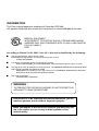
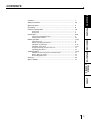
DIGITAL COLOR PRINTER
MODEL
CP900DW
OPERATION MANUAL
FEED&CUT
RESET
COPY
THIS OPERATION MANUAL IS IMPORTANT
TO YOU.
PLEASE READ IT BEFORE USING YOUR
DIGITAL COLOR PRINTER.
This digital color printer complies with the requirements of the EC
Directive 89/336/EEC, 73/23/EEC, 93/42/EEC and 93/68/EEC.
The electro-magnetic susceptibility has been chosen at a level that
gains proper operation in residential areas, on business and light
industrial premises and on small-scale enterprises, inside as well as
outside of the buildings. All places of operation are characterised by
their connection to the public low voltage power supply system.
INFORMATION
This Class A digital apparatus complies with Canadian ICES-003.
Cet appareil numérique de la classe A est conforme à la norme NMB-003 du Canada.
MEDICAL EQUIPMENT
WITH RESPECT TO ELECTRIC SHOCK, FIRE AND MECHANICAL
HAZARDS ONLY IN ACCORDANCE WITH UL 2601-1 AND CAN/CSA
C22.2 NO. 60601.1.
57RF
According to Clause 5 in UL 2601-1 sec 6.8.1, this unit is classified by the following;
2
2
2
2
The type of protection against electric shock:
EQUIPMENT energized from an external electrical power source:
CLASS I EQUIPMENT
The degree of protection against harmful ingress of water:
Ordinary EQUIPMENT (enclosed EQUIPMENT without protection against ingress of water)
The degree of safety of application in the presence of a FLAMMABLE ANAESTHETIC MIXTURE WITH
AIR or WITH OXYGEN OR NITROUS OXIDE:
EQUIPMENT not suitable for use in the presence of a FLAMMABLE ANAESTHETIC MIXTURE
WITH AIR or WITH OXYGEN OR NITROUS OXIDE
The mode of operation:
CONTINUOUS OPERATION
WARNING :
TO PREVENT FIRE OR SHOCK HAZARD, DO NOT EXPOSE THIS
APPLIANCE TO RAIN OR MOISTURE.
This product is to be employed with medical equipment, just for
reference purpose, not for medical diagnostic purpose.
When you dispose of the unit or accessories, you must obey the
law in the relative area or country and the regulation of the
medical facility.
CAUTION
RISK OF ELECTRIC SHOCK
DO NOT OPEN
CAUTION: TO REDUCE THE RISK OF ELECTRIC SHOCK,
DO NOT REMOVE COVER (OR BACK)
NO USER-SERVICEABLE PARTS INSIDE
REFER SERVICING TO QUALIFIED SERVICE PERSONNEL.
The lightning flash with arrowhead symbol, within an
equilateral triangle, is intended to alert the user to the
presence of uninsulated "dangerous voltage" within the
product's enclosure that may be of sufficient magnitude to
constitute the risk of electric shock.
The exclamation point within an equilateral triangle is
intended to alert the user to the presence of important
operating and maintenance (servicing) instructions in the
literature accompanying the appliance.
NOTE:
This equipment has been tested and found to comply with the limits for a Class A digital
device, pursuant to Part 15 of the FCC Rules. These limits are designed to provide reasonable
protection against harmful interference when the equipment is operated in a commercial
environment. This equipment generates, uses, and can radiate radio frequency energy and,
if not installed and used in accordance with the instruction manual, may cause harmful
interference to radio communications. Operation of this equipment in a residential area is
likely to cause harmful interference in which case the user will be required to correct the
interference at his or her own expense.
WARNING:
Use the included AC power cord so as not to interfere with radio and television reception.
If you use other cables, it may cause interference with radio and television reception.
CONTENTS
PRECAUTIONS
1
2-4
5
6
7-8
FEATURES
Contents ................................................................................................
Safety precautions ................................................................................
Special features ....................................................................................
Unpacking .............................................................................................
Features and functions .........................................................................
Front panel ............................................................................................. 7
Rear panel ............................................................................................. 8
Connections .......................................................................................... 9-10
Connection with USB interface .............................................................. 9
Setting mode switches ........................................................................... 10
CONNECTIONS PREPARATION
Before operation .................................................................................... 11-16
Paper sheet set ......................................................................................
Unlock the printing mechanism ..............................................................
Installation of print paper ........................................................................
Installation of ink sheet ..........................................................................
Usage and storage of paper sheet set ...................................................
Installing printer driver ............................................................................
11
11
11-13
13-15
15
16
Troubleshooting .................................................................................... 17-19
Indication on the front panel & countermeasures .................................. 17
Before calling for service ........................................................................ 18
Overcoming paper jams ......................................................................... 19
Cleaning ................................................................................................ 20
Spec & options ...................................................................................... 21
TROUBLESHOOTING
OTHERS
1
SAFETY PRECAUTIONS
In the interest of safety, please observe the following precautions:
POWER REQUIREMENT
This product is designed for operation on 120V AC or 220-240V AC 50/60Hz. Never connect to any outlet or power supply
having a different voltage or frequency.
WARNING: THIS APPARATUS MUST BE GROUNDED.
AVERTISSEMENT: CET APPAREIL DOIT ETRE MIS A LA TERRE.
PROTECTIVE MEASURES
IF ABNORMALITIES ARISE, ....
If the printer emits smoke or abnormal sounds, immediately unplug the power cord from the printer or power outlet. Continued
use may be dangerous. Contact your dealer about having the printer checked and serviced.
NEVER INSERT ANY OBJECT INTO THE UNIT
Nothing other than supplies for this printer should ever be inserted into the printer. Other items can cause a safety hazard and
extensive damage to the mechanism and electronics.
DO NOT SET HEAVY OBJECTS ON TOP OF THE UNIT
Heavy objects can damage the unit and/or cause misoperation.
AVOID DAMAGING THE POWER CORD
Do not set anything heavy on the power cord nor allow it to become pinched, or cut. If the power cord becomes damaged,
replace it immediately to avoid shock hazard or electrical fire.
When the power cord is replaced, use the same type as originally supplied, it is designed to reduce interference to radio & TV
reception.
When unplugging the power cord, hold the plug, and remove it carefully.
KEEP THE UNIT DRY - DO NOT PLACE WATER OR OTHER LIQUID CONTAINERS ON TOP OF THE UNIT
Liquids which get into the unit can cause serious damage to the unit and potential shock or fire danger. If liquid is spilled into or
seeps into the unit, unplug the Power Cord immediately and seek service as soon as possible to avoid additional or possible
damage due to corrosion.
“In the interest of safety, avoid handling of liquids near the unit.”
DO NOT REMOVE THE CABINET. THERE ARE NO USER SERVICEABLE PARTS INSIDE AND YOU WILL EXPOSE
YOURSELF TO HAZARDOUS VOLTAGES AND/OR YOU MAY CAUSE DAMAGE TO THE UNIT.
Touching internal parts is dangerous, and may cause a malfunction. Contact your dealer to carry out internal checks and
adjustments. Disconnect the power cord before opening the cover to clear a paper jam, etc.
UNPLUG THE POWER CORD DURING A LONG ABSENCE OR DURING AN ELECTRICAL STORM
Turn off the Main Power switch and unplug the power cord during a long absence or during an electrical storm.
WHEN TRANSPORTING THE UNIT
When transporting the unit, remove the sheet cartridge and paper. Make sure to slide the printing mechanism lock switch to the
lock position.
BE CAREFUL AROUND PRINT PAPER EXIT SLOT
Do not insert your fingers or any object into the paper slot during printing.
Do not touch the cutter blade inside the paper exit slot, it can cause injury.
DO NOT TOUCH THE THERMAL HEAD
It becomes hot during printing and may remain hot for a time, causing injury. Oils, salts and moisture from your hands will
contaminate the head and may spoil the prints.
2
BE CAREFUL WITH THE PRINTING MECHANISM
PRECAUTIONS
Do not move the printer while the printing mechanism is open. This may cause injury.
Be careful not to catch your fingers in the printing mechanism when sliding the mechanism back into the normal closed position.
CONNECTING CABLES
Use the power cord supplied with the printer.
INSTALLATION LOCATIONS
Ventilation slots and holes are provided on the rear, sides and bottom of this unit. Place the unit on a hard and level surface and
locate at least 4 inches (10 cm) from walls to insure proper ventilation. When installing the unit in a system rack, leave space
between the unit and the back of the rack.
CONNECTIONS PREPARATION
UNSUITABLE LOCATIONS
FEATURES
MAINTAIN GOOD VENTILATION
Avoid installing the printer in unstable locations with high vibration or in hot-springs areas where hydrogen sulfide and acidic
ions are likely to be generated.
PLACES WITH HIGH HUMIDITY AND DUST
Do not place the unit in locations with high humidity and dust, as this can cause extensive damage. Avoid places where unit is
likely to be exposed to oily fumes and vapours.
PLACES LIKELY TO BE EXTREMELY HOT
Places exposed to direct sunlight, or near heating appliances can attain extremely high temperatures which may deform the
cabinet, or cause other damage.
PLACE THE UNIT ON A HORIZONTAL SURFACE
The operation of the unit is likely to be affected if it is tilted, inclined or in unstable places.
When the unit is moved from a cold area into a warm area, moisture can condense inside the unit and prevent operation. Allow
the temperature to stabilize before use.
OPERATING AMBIENT TEMPERATURE RANGE
The operating temperature range is 41°F - 104°F (5°C to 40°C) and humidity of 20 - 80%. When using the unit in a system rack,
make sure that the temperature inside the rack does not exceed this range.
TROUBLESHOOTING
PROTECT AGAINST DEW FORMATION
OTHERS
FOR LONG OPERATING LIFE
UNSUITABLE MATERIALS FOR THE PRINTER
Paint coat flaking and plastic deformation are likely to occur if the unit is wiped with chemical dusters, benzine, thinner or any
other solvent, if rubber or PVC items are left in contact with the unit for a extended period, or if the unit is sprayed with
insecticide.
CARE OF THE CABINET
Unplug and clean with a soft cloth slightly moistened with a mild soap and water solution. Allow to dry completely before
operating. Never use petroleum based solutions or abrasive cleaners.
HEAD ABRASION
The thermal printhead, like a video head, wears out. When it is worn, it becomes hard to print out fine details of the picture. If it
occurs, consult your dealer about having the head replaced.
3
SAFETY PRECAUTIONS
CONNECTING DEVICES
Read thoroughly the Safety Notices, Cautions and “Operating Precautions” of the instruction booklets for the other devices
connected with the unit.
CAUTION ON RELOCATING
When transporting the unit, make sure it is not likely to be subjected to impacts. This can be a primary cause for damage.
Before moving the unit, make sure to disconnect the power cord from the power outlet, and the cables from the connected
devices.
SAFETY CHECKS
Periods:
Scope: a)
According to the recommendations of the manufacturer of medical device.
Visual inspection
Housing, leads, controls, displays, labels/ markings, accessories, operation manual.
b)
Functionality test
Testing of functions (according to operation manual) as well as compatibility and usability of device and accessories.
c)
Electrical test
Testing of electrical safety of the system according to EN60601-1.
High humidity or dust
Avoid locations with high humidity and dust in order to avoid malfunction.
Also avoid locations subject to corrosive gasses and smoke.
Heat
Direct sunlight, heaters or other heat sources may deform the housing and subsequently cause malfunctioning.
TECHNICAL DESCRIPTION
The supplier will make available on request such circuit diagrams, component part lists, descriptions, calibration instructions or other information
which will assist the USER’s appropriately qualified technical personnel to repair those parts of the EQUIPMENT which are classified by the
manufacturer as repairable.
The use of ACCESSORY equipment not complying with the equivalent safety requirements of this equipment may lead to a reduced level of
safety of the resulting system. Consideration relating to the choice shall include:
- use of the accessory in the PATIENT VICINITY
- evidence that the safety certification of the ACCESSORY has been performed in accordance to the appropriate EN60601-1 and/or EN60601-11 harmonized national standard.
The transportation and storage environmental conditions are:
Temperature : -20°C - +60°C (-4°F - +140°F)
Humidity : 90%RH or less at 40°C(104°F)
Atmospheric pressure : 500 hPa - 1060 hPa
OTHER CAUTIONS
Dust or other foreign matter adhering to the print paper or the sheet cartridge, or deformation resulting from exposure to
extremely low or high temperatures could cause loss of color, uneven color or lines, or wrinkles in the print images.
NOTE:
MEMORIZED IMAGES ARE STORED IN VOLATILE MEMORY AND MAY BE LOST IN THE EVENT OF POWER
FLUCTUATION OR MALFUNCTION.
As for paper sheet set, refer to page 21, “Options”.
WARNING :
Use the USB cable according to the recommendations as below, in order to comply with EN60601-1-2.
The USB cable with appropriate plug should be 2m long or shorter, comply with USB 2.0 standard High speed requirements and USB IF (USB Implementers Forum) approved.
Information:
This equipment complies with EN55011, class B, group 1.
4
SPECIAL FEATURES
SPECIAL FEATURES
PRECAUTIONS
2 PRINT SIZES ARE AVAILABLE DEPENDING ON INK SHEET
2 printing sizes, L size (max.110 x 162 mm) and S size (max.110 x 105 mm), are selectable.
HIGH SPEED PRINTING
Printing speed is approx. 12 seconds (in S size print).
LARGE CAPACITY PRINT MEDIA
FEATURES
S size media has a maximum of 200 prints per roll.
HIGH QUALITY PRINTING
High quality print is available in dye sublimation mode. It also employs 256 gradients in each YMC, and about 16,700,000
colours total.
CONNECTIONS PREPARATION
325 PPI HIGH RESOLUTION
325 PPI (Pixel Per Inch) high resolution gives precise illustrations and sharp photo images.
UNIQUE COLOUR IMAGE CONTROL SYSTEM WITH THE IC CHIP ATTACHED TO THE INK SHEET ROLL
By setting the supplied IC chip to ink cassette, the remaining print count of the ink sheet can be displayed. The IC also controls
the colours of the printed images.
TROUBLESHOOTING
OTHERS
5
UNPACKING
UNPACKING
Take the unit out of the box by the following procedures. Make sure to check the contents.
1
Open the top of the box.
O R
DE O
VI SS
UR CE
LO PRO
CO PY
CO
2
Be careful not to drop the contents.
3
Make sure to keep the unit horizontal.
O R
DE O
VI SS
UR CE
LO PRO
CO PY
CO
4
Remove the cushion with contents.
Take the unit out of the box carefully.
Unwrap the packing.
2 CONTENTS
Make sure to check the supplied contents on the cushion.
Power cords (2)
DIGITAL
COLOR PRINTER
Ink cassette
Operation manual
Printer driver (1 floppy disk)
6
Spacers (4)
Screws (4)
FEATURES & FUNCTIONS
1 2345
PRECAUTIONS
FRONT PANEL
6 78
FEED&CUT
RESET
COPY
FEATURES
C
1 POWER BUTTON(INDICATOR)
8 COPY BUTTON
2 ALARM INDICATOR
9 PRINT OUTLET
3 SHEET ERROR INDICATOR
A OPEN BUTTON
Press to turn on power. Press again to turn off power.
When the power is turned on, the indicator illuminates.
When this unit is overheated, this lamp flashes. When other
errors occur, the LED is steady. See page 17.
4 PAPER ERROR INDICATOR
When an error concerning print paper occurs, this indicator
lights up or blinks.
The printed paper comes out here.
Do not put any objects in front of the outlet.
C
Press to slide out the printing mechanism. Make sure to
unlock
PRINTING UNIT LOCK SWITCH. Reset the
power if this button does not open the printing mechanism.
Then try to press this button again.
Open the mechanism to load paper and ink cassette or to
clear a paper jam.
B TRAY
6 FEED&CUT BUTTON
C PRINTING MECHANISM LOCK SWITCH
Indicator blinks during data transfer. It is steady while
printing and during feed&cut function.
Pressing this button, the print paper is fed and cut. And
the mechanism will be initialized.
7 RESET BUTTON
Reset the print count to 1 when this button and
FEED&CUT button are pressed together.
6
Hold the printed image that comes out of the print outlet.
Press down and pull the knob to extend the tray. Make
sure to fully extend the tray for proper use.
Locks the printing mechanism.
Shift the switch to the left (LOCK side) to lock and to the
right (UNLOCK side) to unlock.
This mechanism is locked when shipping. When
transporting this unit, make sure to lock the mechanism.
7
OTHERS
5 DATA INDICATOR
TROUBLESHOOTING
When an error concerning ink sheet occurs, this indicator
lights up or blinks.
When pressing this button, the memorized data will be
printed.
CONNECTIONS PREPARATION
9
A
B
FEATURES & FUNCTIONS
REAR PANEL
1
2
3 4
87654321
REMOTE
OFF
ON
5
USB
AC LINE
6
1 REMOTE TERMINAL
4 USB PORT
2 MODE SWITCHES
5 Potential equalization connector
Terminal connection for service remote only.
This terminal is to be used by qualified service personnel
only.
Used to set the various functions of this unit. See page
10.
3 USB CABLE CLAMPER
Use this clamper so that the USB port is not disconnected.
Use this terminal to connect the unit to a device equipped
with USB interface such as a personal computer. See page
9 for connection.
This is used to equalize the potential of the equipment
connected to the unit.
For details, refer to the installation instruction of the
equipment to be connected.
6 AC LINE SOCKET
Connects to the provided power cord. Insert the cord firmly.
8
CONNECTIONS
PRECAUTIONS
CONNECTION WITH USB INTERFACE
2 CONNECTING WITH PC
Connect this unit with a personal computer as following example.
FEATURES
To USB port
87654321
REMOTE
OFF
ON
USB
CONNECTIONS PREPARATION
AC LINE
To USB port
Personal computer
Printer
TROUBLESHOOTING
OTHERS
9
CONNECTIONS
SETTING MODE SWITCHES
2 SETTING MODE SWITCHES
Set the mode switches on the rear panel according to the equipment connected.
All the switches are set to OFF as shown right when shipped from the factory.
Turn off the power when changing the mode switch settings.
87654321
OFF
ON
With the switch No.1 and No. 2, the printing speed can be set.
Switch No.
1
2
OFF
OFF
ON
ON
OFF
ON
ON
OFF
Print speed
Prints at the speed set by the printer driver
FINE mode print
FAST mode print
With the switch No.3 to No. 8, the following can be set.
Switch No. Settings
3
4
5
6
7
8
Functions
OFF
Uses the normal gamma curve of images
ON
Uses the gamma curve for connecting to ultrasound diagnostic equipment
OFF
Normal print
ON
Mirror print
OFF
Prints with surface coating
ON
Prints without surface coating
OFF
Not used (Set this switch to OFF.)
OFF
When the printed paper remains at the print outlet, PAPER indicator blinks and this unit stops printing.
ON
Even if the printed paper remains at the print outlet, PAPER indicator remains turned off and this unit
does not stop printing.
OFF
Automatic feed&cut mode
This will cause the printer to perform an automatic feed and cut after installation of the paper and ink
sheet.
ON
10
Manual feed&cut mode
BEFORE OPERATION
PRECAUTIONS
Before printing,
1. Unlock the printing mechanism. (See below)
2. Install the print paper and ink cassette. (pages 11-15)
PAPER SHEET SET
Make sure to use the following types of paper sheet and ink sheet set.
FEATURES
2 PAPER SHEET SET
Ink sheet size
No. of prints
Usage
CK900S
CK900L
S size
L size
200
130
Colour print
Colour print
CK900S4P
CK900L4P
S size
L size
130
90
Surface-laminated colour print
Surface-laminated colour print
CK900S4P(HX)EU
CK900L4P(HX)EU
S size
L size
130
90
Surface-laminated colour print for ID photo
Surface-laminated colour print for ID photo
CONNECTIONS PREPARATION
Product name
UNLOCK THE PRINTING MECHANISM
1
2 RELEASING THE PRINTING MECHANISM LOCK
1 Press down and pull the knob to extend the paper tray.
2
TROUBLESHOOTING
2 Shift the printing mechanism lock switch to the right (UNLOCK). (See
page 8.)
OTHERS
INSTALLATION OF PRINT PAPER
Do not remove the seal on the print paper yet.
Gear
Seal
1 Insert the print paper roller with gear on the left.
Press the folder
1 as shown right, and set the print paper roller.
2
1
Front side
11
BEFORE OPERATION
2 Set the other side of roller without gear.
1
Right side
Left side
3 Remove the seal, and insert the edge of the print paper right below
arrow marks
the roller cover with arrow marks towards the front panel.
Make sure to insert the paper straight.
4 Feed the print paper through the paper outlet.
5 Pull both sides of the print paper to eliminate slack.
Paper
12
Paper
Paper
2 INSTALLING THE INK SHEET
Colored roller
PRECAUTIONS
INSTALLATION OF INK SHEET
White roller
Load the ink sheet roll to the ink cassette before inserting the ink cassette into the printer.
FEATURES
1 Insert the ink sheet rollers gear into the holes of the ink cassette.
Put the white roller (rolled with ink sheet) to the ink cassette first.
Then, insert the colored roller (take-up) to the ink cassette.
CONNECTIONS PREPARATION
2 Put the other sides of rollers. Set IC at this time.
IC chip with the IC holder is attached to the ink sheet.
Set the IC holder to the ink cassette as shown right.
•
NOTE
Do not remove the IC chip or IC holder from the ink sheet.
Removal of the IC will stop the printer from functioning correctly.
•
Set the projected part of the IC holder to the correct position as shown below.
TROUBLESHOOTING
IC holder
OTHERS
Projected part
2 INSTALLING THE INK CASSETTE
1 Eliminate any slack of the ink sheet.
Hold the colored roller and turn the white roller.
13
BEFORE OPERATION
2 Insert the ink cassette with the ink sheet into its compartment.
Put the ink cassette into the printer drawer as shown
1. Then, set the other side
(with handle) as shown right. When exchanging the ink cassette, remove it by
holding the handle. (See page 19.)
1
1
2
2 INSERT THE PRINTING UNIT
1 Push the printing unit until it is locked into place.
2 After plugging the power cord, press POWER button on the
front panel.
3 Press FEED & CUT button.
The print paper is automatically cut after feeding about 10 cm (4 inches).
4 Repeat the above step 3 once or twice.
Feeding the print paper will eliminate fingerprints and dust during handling. The
printing unit is initialized.
•
NOTE
Do not feed the print paper more than 2 times. Doing so will not allow the number of prints
indicated on page 11 to be printed.
The installation of print paper and ink cassette is completed.
NOTE
An IC is built in the ink sheet. This is the IC chip, not a battery.
This IC can be thrown away as normal waste.
14
2
PRECAUTIONS
NOTE
Take the print paper one by one after completing printing. Pull out the tray completely when
using it. If you fail to do so, paper jamming may occur.
Put the tray back after printing.
USAGE AND STORAGE OF PAPER SHEET SET
Fingerprints or dust on the paper’s surface may degrade print quality and cause paper jams.
Immediately after the paper is replaced, 2 images may be printed with a blank part due to
fingerprints. Refer to Pages 11 - 12.
•
When print paper is rapidly transferred from a cool place to a hot place, vapor or dew will be
generated on the paper’s surface causing paper jams or degraded print quality. Leave the
print paper in the room to stabilize its temperature before use.
•
When print paper and ink sheet run out during printing, the printing operation stops and the
SHEET and/or PAPER lamp on the front panel will be lit or blink. Set new ink sheet or print
paper. Refer to Pages 11-15.
•
Excessive paper feeding will reduce total print count.
•
When the image comes into contact with water, the print may be discolored.
•
Fading may occur if the print-face is exposed to organic chemical agents which may affect
print paper (e.g. alcohol, ester, ketone based).
•
Fading will be accelerated upon contact with PVC-based materials (e.g. adhesive tapes,
rubber erasers, etc.).
•
Avoid storing prints in direct sunlight or places with high humidity.
•
Leaving the print paper in contact with PVC-based materials causes color of print paper to
change or staining to occur.
•
Never store print paper in places that are close to heat sources, high humidity or dust.
Keep print paper in a place where;
Temperature : 5°C - 30 °C (41°F - 86°F)
Humidity
: 20 - 60%RH
CONNECTIONS PREPARATION
•
FEATURES
2 BEFORE PRINTING
2 AFTER PRINTING
TROUBLESHOOTING
2 STORAGE
OTHERS
15
BEFORE OPERATION
INSTALLING PRINTER DRIVER
A printer driver is required to print the data from a personal computer connected with this unit.
The printer driver for Windows® is supplied with this unit.
Product name
Operating conditions
CPD900W
Applies for Microsoft®Windows®98 and Windows® Me
CPD900N0
Applies for Microsoft®Windows® 2000 and Windows XP®
Refer to the “Read me” for installing the printer driver in the floppy disk supplied with this unit.
2 How to open the ReadMe file
1 Install the floppy disk in the floppy disk drive on your PC.
2 Double-click on the floppy disk icon.
3 Double-click on the ReadMeE.TXT or ReadMeE.pdf.
Adobe Acrobat Reader is required to open ReadMeE.pdf file. You can download Acrobat Reader free from the Web site of
Adobe Systems Incorporated (http://www.adobe.com/products/acrobat/).
4 Install the printer driver by following the instruction in the file.
Windows®98, Windows®Me, Windows® 2000 and WindowsXP® are the registered trademarks of Microsoft Corporation in the
U.S.A. and other countries.
Adobe and Acrobat are registered trademark of Adobe Systems Incorporated.
16
TROUBLESHOOTING
INDICATION ON THE FRONT PANEL & COUNTERNEASURES
PRECAUTIONS
If for some reason printing is not possible or error occurs during printing, the indicators on the front panel will be lit.
In this case, follow the procedure described below.
: lit
ALARM SHEET PAPER DATA
Causes
Paper is used up.
Paper is not installed.
: not lit
Countermeasures
• Set a new roll of paper.
Refer to pages 11-13.
IC chip is not installed.
The data in IC chip cannot be read
correctly.
• Use an ink sheet with the attached IC chip.
• Set the attached IC chip on an ink sheet.
• Use the correct ink sheet with IC chip.
IC chip and the ink mark are not the
same.
A wrong media type is set.
• Use correct IC chip and ink sheet.
The ink cassette is not installed.
• Install the ink cassette.
Refer to pages 13-15.
The ink sheet and the print paper are
not combined correctly.
• Use them in the correct combination.
The temperature of the thermal head
becomes too high.
• Wait until the ALARM indicator goes off.
*Note
The print paper is left at the print outlet.
• Remove the print paper.
Paper jam occurs.
• Refer to page 19 “Overcoming paper jams”.
Press FEED&CUT button.
Other defects.
• Press FEED&CUT button.
In case of paper jam, refer to page 19
“Overcoming paper jams”.
If the status is not improved by carrying out this
measure, consult your dealer.
TROUBLESHOOTING
• Replace the ink sheet with a new one.
Refer to pages 13-15.
CONNECTIONS PREPARATION
The ink sheet is used up.
FEATURES
*Note :
: blinks
When setting the continuous printing, this unit starts printing again after the indicator goes off.
OTHERS
17
TROUBLESHOOTING
BEFORE CALLING FOR SERVICE
2
Use the following troubleshooting chart to try to resolve any apparent defect in operation. If you are unable to resolve the
problem, unplug the power cord and contact your dealer.
Symptom
Check and Remedy
No power
(when POWER lamp does not illuminate)
Is the power cord plug disconnected from the outlet?
→ Connect the power cord plug to the outlet firmly.
After tuning the power off, wait for approx. 2 minutes. Then turn on the
power.
The image is not printed.
Is the image data sent to this unit?
Is the print paper or ink sheet used up?
Is the printing mechanism set correctly?
→ Check the status.
The stored image in the memory cannot be
enlarged to fill the maximum print area.
Is the appropriate image data transferred?
Is the S-size image data sent for L-size print paper?
→ Check the status.
COPY button does not work.
Is the image data transferred?
→ Send an image data.
If the power is turned off and then turned on after sending the data, the
COPY button does not work.
Though the print paper is not left at the
print outlet, PAPER indicator blinks and
DATA indicator goes on.
18
→ The sensor for detecting remaining paper may fail to work properly due
to infrared light and so on.
Set the mode switch No. 7 on the rear panel to ON.
OVERCOMING PAPER JAMS
PRECAUTIONS
1 Press OPEN button to pull out the printing mechanism.
When it is not working, reset the power. Then try to press OPEN button again.
FEATURES
2 Remove the ink cassette with ink sheet.
CONNECTIONS PREPARATION
3 Remove the print paper as shown right.
2
1
4 Cut the defective part of the print paper with scissors.
TROUBLESHOOTING
5 Cut both edges of the print paper.
OTHERS
6 Install the print paper. (Refer to pages 11-13.)
19
CLEANING
CLEANING
A small amount of alcohol
Cleaning as indicated below will help maintain stable printer operation and extend the
printer’s life.
Preparations
Alcohol (isopropyl alcohol)
Cleaning part
How to hold tissue paper
Tissue paper (Fold in half about 4 times, and use the folded side to clean.)
Cotton buds
Cleaning kit (Option)*
Other : Cleaner pen (Option)*
*Please ask the dealer about options.
Cleaner pen (Option)
Make sure to turn off the power before cleaning.
1 Press OPEN button to pull the printing mechanism out.
2 Remove the ink cassette and print paper.
3 Wipe the ink sheet sensor.
Ink sheet sensor
Front panel
Clean the parts circled in the right figure.
Carefully wipe with tissue paper etc. which is soaked in a small amount of alcohol.
4 Wipe the ink sheet sensor reflection plate.
Clean the metal reflection plate.
Carefully wipe with tissue paper etc. which is soaked in a small amount of alcohol.
5 Wipe the head.
Ink sheet sensor reflection plate
Thermal head
Cleaning the part under the thermal head which develops heat.
Wipe the head cleaning part carefully with tissue paper etc. which is soaked in a
small amount of alcohol.
•
NOTE
Do not damage the thermal head.
•
When the symptom of the poor print quality is not corrected even if the head is
cleaned, replacing the thermal head is required. Contact your dealer.
•
Thermal head is hot right after printing. Wait until the head cools before cleaning
the thermal head.
6 Clean the rubber roller.
Dust etc. can build up on the rubber roller after prolonged use. Carefully wipe with
tissue paper etc. which is soaked in a small amount of alcohol.
Rubber roller
20
SPEC & OPTIONS
SPECIFICATIONS
Print quality
Ink sheet
Print paper
Installation conditions
Operation altitude
Outside dimensions
Weight
Accessories
CONNECTIONS PREPARATION
Supply method
Interface
Power supply
Power consumption
Digital color printer
CP900DW
Thermal Dye Sublimation
3 colour faces progressive printing (yellow, magenta and cyan) and surface lamination
Dot resolution
Max. 1280 x 960 pixels (S size)
325 PPI
Max. 1676 x 1280 pixels (L size) PPI : Pixel Per Inch
256 (8 bits) for each colour ( About 16.7 million colours)
S size Approx. 12 sec./sheet (No surface coated)
L size Approx. 18 sec./sheet (No surface coated)
Special cartridge method
Special roll paper
S size 110 x 105mm
Printing area 100 x 75mm
L size 162 x 110mm
Printing area 130 x 100mm
Automatic (roll paper)
USB Ver1.1
AC120V, 50/60 Hz, AC 220-240V, 50/60Hz
1.4A (AC120V, 50/60Hz) during priting (0.2A when not printing)
0.7A (AC220-240V, 50/60Hz) during priting (0.1A when not printing)
Temperature
: 5°C - 40°C (41°F - 104°F)
Humidity
: 20% - 80% (No dewing)
Atmospheric pressure : 700 hPa - 1060 hPa
Within Horizontal ±5°
280(W) x 150(H) x 400(D) mm
11kg
Power cords (2), Ink cassette (1), Operation manual (1), Printer driver (1 floppy disk),
Spacer (4), Screw(4)
FEATURES
Number of grades
Printing time
PRECAUTIONS
Class
Model
Printing method
TROUBLESHOOTING
OPTIONS
Product name
CK900S
CK900L
CK900S4P
CK900L4P
CK900S4P(HX)EU
CK900L4P(HX)EU
Ink sheet size
S size
L size
S size
L size
S size
L size
No. of prints
200
130
130
90
130
90
OTHERS
2 PAPER SHEET SET
Usage
Color print
Color print
Surface-laminated color print
Surface-laminated color print
Surface-laminated color print for ID photo
Surface-laminated color print for ID photo
21
MITSUBISHI DIGITAL ELECTRONICS AMERICA, INC.
9351 Jeronimo Road, Irvine, CA 92618, U.S.A.
Phone 949-465-6000
Mitsubishi Electric Europe B.V.
UK Branch
Travellers Lane, Hatfield, Herts. AL10 8XB, England, U.K.
Phone (0) 1707 276100 FAX (0) 1707 278755
German Branch
Gothaer Strasse 8, 40880 Ratingen ; Postfach 1548, 40835 Ratingen ; Germany
Phone (2102) 486-9250 FAX (2102) 486-7320
French Branch
25, Boulevard des Bouvets - 92741 NANTERRE cedex
Phone (01) 55.68.55.00 FAX (01) 55.68.57.31
Italian Branch
Centro Direzionale Colleoni, Palazzo Perseo-Ingresso 2,
Via Paracelso 12, 20041 Agrate Brianza, (Milano) Italy
Phone (039) 60531
FAX (039) 6057694
Benelux Branch
Nijverheidsweg 23 A, 3641 RP. Postbus 222, 3640 AE Mijdrecht
Phone 02972-82461
FAX 02972-83936
Spanish Branch (Barcelona)
Sucursal en españa
Polígono Industrial "Can Magí", Calle Joan Bucallà 2-4,
Apartado de Correos 420, 08190 Sant Cugat del Vallês,
Barcelona, Spaín
Phone 93.5653154
FAX 93.5894388
Manufactured by Mitsubishi Electric Corporation
1 Zusho Baba, Nagaokakyo-city, Kyoto Japan
Made from recycled paper
PRINTED IN JAPAN
871C593A4