1
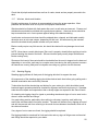
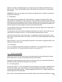
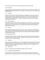
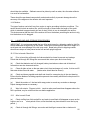
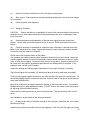
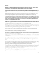
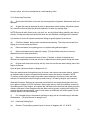
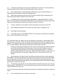
CS36
Owner’s Manual
CS YACHTS LTD., 79 .Bramsteele Road, Brampton
Ontario, Canada. L6W 3K6
(416) 457-6713
TELEX: 06-97537
1
TABLE OF CONTENTS
1.
2.
3.
4.
5.
6.
7.
8.
9.
10.
11.
12.
13.
14.
15.
16.
17.
INTRODUCTION ...........................................................................................................3
LIST OF TABLES...........................................................................................................4
LIST OF ILLUSTRATIONS (DETAILS) ..........................................................................4
PRINCIPAL SPECIFICATIONS AND DIMENSIONS - CS 36.........................................5
CONSTRUCTION ..........................................................................................................6
RIGGING .......................................................................................................................7
POWER PLANT AND TRAMSMISSION ........................................................................9
FUEL SYSTEM ............................................................................................................13
ELECTRICAL...............................................................................................................13
ELECTRONICS ...........................................................................................................14
CONTROLS.................................................................................................................15
ACCESSORIES............................................................................................................16
MAINTENANCE...........................................................................................................17
SAFETY EQUIPMENT.................................................................................................23
LAUNCHING AND STORAGE PROCEDURES ...........................................................25
WINTER LAY-UP AND STORAGE ..............................................................................28
WARRANTY ................................................................................................................33
2
1.
INTRODUCTION
This manual will help you to know you new CS Yacht. Read your manual carefully as
well as the manufacturer’s components manuals supplied with your yacht.
It is most important to familiarize yourself thoroughly with all aspects of operating and
maintaining your yacht in a safe and efficient manner.
If any questions remain that you cannot solve, your CS dealer will be only too pleased to
clarify them.
If you find your yacht equipped with different gear from what is shown in your manual, it
is usually due to our continuing effort to upgrade and improve our line of yachts. Any
new piece of equipment will be usually equal or better.
We will therefore keep you informed through your dealer of any changes or
improvements that have been made relating to your particular yacht.
On taking delivery of your yacht, fill in the warranty card or change of ownership card
and be sure to read and understand the CS warranty. Return the card to CS Yachts as
soon as possible.
3
2.
LIST OF TABLES
1.
2.
3.
4.
5.
6.
7.
8.
9.
3.
Lubricants and Coolants
Electrical Light Bulb Replacement
Tank Capacities, Toilet, Stove and Faucet Types
Stainless Steel and Rigging Components
Standing Rigging
Running Rigging
Blocks
Backstay Preload Limits
Engine and Propeller
LIST OF ILLUSTRATIONS (DETAILS)
1
2
3
4
5
6
7
8
9
10
11
12
13
14
15
16
17
18
19
20
20A
21
22
23
24
25
Hauling Sling Location
Mast Sling Location
Mast and Rigging Layout
Standard Halyard Arrangement
Standard Arrangement for Optional Halyards
Masthead Detail
Gooseneck and Spreader Details
Deck/Hull Joint
Keel Connection
Rudder Shaft
Through Hull Fitting
Propeller Shaft Seals (Stuffing Box)
Standard 2-Blade Propeller
Mast Lighting System
V.H.F. Connections
Through Hull Locations (Dock Plan)
Fuel Tank and Lines
Propane System with Electrical S.A.V. Shut-off
Hot and Cold Water Pressure System and Shower System
Hand Pump System
Isometric View of Plumbing System
Engine Cooling Circuits
Toilet Plumbing System
Bilge Pump System
Peck Plan and Accommodations
Cradle Dimensions
Note : See also the large-scale drawings of sail plan, wiring diagram, docking plan, etc., as
supplied by CS Yachts, at the back of the manual.
4
4.
PRINCIPAL SPECIFICATIONS AND DIMENSIONS - CS 36
Principal Dimensions
L.0.A.
36'- 6"
11.13 m
L.W.L.
29'- 3"
8.92 m
Beam
11'- 6"
3.50 m
Draft
- Deep
- Shoal
6'- 3"
4' - 11"
1.90 m
1.52 m
Displacement
approx
15,500 lbs.
7021 kg.
Ballast Keel
Deep, approx
6,500 lbs.
2944 kg.
Shoal, approx.
6,650 lbs
3012 kg.
Clearance and Shipping Dimensions
Masthead to waterline(ex
antenna, etc.)
Pulpit to waterline (mast
lowered)
Height overall in shipping
cradle
52' - 10"
16.11 m
6’- 7"
2.00 m
- Deep
12' - 1"
3.68 m
- Shoal
10' - 10"
3.30m
16,300 lbs.
7393 kg.
54' - 5"
16.58 m
5.3" x 7.9"
127 x 205 mm
Shipping weight in cradle with
spars approx.
Mast length
Mast section
Tankage
Freshwater
Waste holding
Fuel
Battery capacity
82
Imp. Galls.
32
Imp. Galls.
35
Imp. Galls.
2 x 112 Amp. Hrs.
372 L
145 L
159 L
5
Sail Plan Dimensions
I
J
LP
P
E
SPL
SL
SMW
Main Sail
No.1 Genoa- heavy
No.1 Genoa- light
No. 2 Genoa
No. 3 Genoa
Jib
Storm Jib
Spinnaker approx.
Sail Area -100% Foretriangle
Sail Area - Actual with #1-150%
5.
49.0'
15.0'
22.5'
42.75'
12.75'
15.0'
48.68'
27.0'
272 sq. ft.
551 sq. ft.
551 sq. ft.
492 sq.' ft.
391 sq. ft.
270 sq. ft.
104 sq. ft.
1,200 sq. ft
640 sq. ft.
822 sq. ft.
14.94 m
4.57 m
6.86 m
13.03 m
3.88 m
4.57 m
14.84 m
8.23 m
25.26 sq. m
51.18 sq. m
51.18 sq. m
45.70 sq. m.
36.32 sq. m.
25.08 sq. m.
9.66 sq. m.
111.48 sq. m.
59.36 sq. m.
76.45 sq. m.
CONSTRUCTION
5.1 HULL
The hull of the CS 36 yacht is a one-piece fibreglass moulding. The hull is hand laid up with the
finest materials available and reinforced at key points of stress. The CS 36 is made even
stronger by a moulded spline and girder section down the centre of the yacht.
The stresses of the mast and keel are accepted by this module giving the yacht exceptional
integrity. The boot top and top accent strip are permanently moulded into the hull.
5.2 DECK/HULL CONECTION
Detail NO. 8 illustrates the strong hull-to-deck joint. On assembly, the top of the hull flange is
capped with a soft butyl rubber gasket. The deck is fastened with stainless steel through bolts
to the hull flange.
Upon tightening the bolts the butyl compound is forced into remaining crevices.
Should a leak develop at the deck/hull joint the through bolts in the area may be tightened,
ensuring that the bolt does not turn while tightening the nut.
5.3 DECK
6
The deck and cockpit is a single-unit fibreglass moulding surfaced with gelcoat. The deck and
horizontal section is moulded in a sandwich of endgrain balsa to give additional stiffness. A
non-skid finish is moulded into the working areas of the deck.
5.4 STEERING AND RUDDER
The yacht is fitted with pedestal steering and wheel, a radial driver turned by the wheel through
a cable system, clamped to the rudder post and through bolted. See manufacturer's
maintenance instructions and Sections 13.10 under Maintenance
The stainless rudder stock is a two-point attachment system. It is housed in a bearing gland
which is through bolted to a mounting flange integral with the hull laminate The lower end of the
stock is supported by a lower bearing through bolted to the skeg.
5.5
BALLAST
The keel of your CS Yacht is lead alloyed with antimony for added strength and cast to close
tolerances.
The keel is through-bolted with oversize 316 stainless steel bolts that have been cast into the
lead. The tensile strength of these bolts is greater than 7,000 lbs. Each of the 12 bolts is
capable of carrying the keel by itself. Eight of the 12 bolts are double-lugged. These bolts are
also embedded at various depths in the lead keel itself. (See dwg. No. 9)
6.
RIGGING
6.1 General
It is important to understand the principles involved in order to do an effective job of mast tuning.
Terms and Definitions
Standing rigging refers to fixed lengths of stainless steel wire or rod supporting the mast. If they
offer fore and aft support, they are called forestay and backstay. If the support is principally
transverse they are called shrouds. (See also Detail No. 3, Mast and Rigging Layout, and
Tables No. 4,5,6 and 7)
6.2 Spars
The mast on your CS .36 is supported by three sets of shrouds. Those running from the
masthead to deck are known as upper or cap shrouds.
Intermediate shrouds, fixed at the inner end of the upper shrouds, run through the tip of the
lower spreaders to the chainplates.
Two sets of lower shrouds are fitted, known as forward and aft lowers. Lower shrouds, led to
chainplates forward and aft of the mast centreline, provide some fore and aft support.
To reduce the large tensile forces in the shrouds and compressive load in the mast, the upper
7
and intermediate shrouds are led over spreaders. The upper spreaders lead the shrouds out
from the mast and provide a deflection of approximately 12°, which is considered ideal.
However, the shrouds impart a side load, acting horizontally along the spreader. The
intermediates take some of this load off the mast at the upper spreader, while the lower shrouds
do the same at the lower spreader.
It is obvious that the more standing rigging that is used transversely and longitudinally, the stiffer the rig will be, allowing a smaller mast section, thus reducing windage.
However, the French-made Isomat spars used by CS, together with the standing rigging
described above provide a very good balance of strength and simplicity.
6.3
Tuning
Tuning involves adjusting the tension of shrouds and stays so that the mast will remain straight
under various sailing conditions and when moored.
Tuning involves two phases:
(a)
Tuning at the dock or while moored
(b)
Fine tuning while sailing
(a)
Tuning at the Dock or While Moored
All turnbuckles should be equipped with toggles at their base as supplied be CS Yachts to
eliminate any bending load on the swage and turnbuckle threads, including both ends of the
forestay.
Start tuning the mast by ensuring that the mast is in the centre of the boat, perpendicular to the
transverse waterline. The mast is set in the forward setting at the mast step. At this point the
rubber mast collar should be set into the mast partners between the mast and deck. This is a
tight fit and can be accomplished best by fitting the collar into place as the mast is being
lowered onto the mast step. If the collar just fits into the fiberglass mast partners with the mast
heel casting 2"-3" away from the mast step, the collar will fit perfectly.
Since boats often do not level at dock due to uneven load distribution of the accommodation
plan and internal weights, slacken all shrouds fully by loosening the turnbuckles. Take the main
halyard and lead the shackle end to a point on the starboard toerail. Adjust the tension on the
halyard so that the end of the shackle just touches the toerail , then cleat the halyard. Move the
shackle to the same location on the port toerail; the end of the shackle should just touch the rail.
Lightly take up on the turnbuckles on the upper shrouds until the mast has been centred.
Now, starting at the lower shrouds, tighten their turnbuckles evenly. Repeatedly sight up the
mast track to ensure that you are not deflecting the lower part of the mast in any direction.
Next, tighten the intermediates, again, ensuring that the mast remains straight, then do the
same on the uppers. When you are sure that the mast is straight, start at the lowers and tighten
each pair of shrouds evenly, by counting the number of turns applied to each. Tighten until the
turnbuckles become difficult to turn.
8
The mast should now be checked for rake.
Rake is the angle, either forward or aft, from vertical. Forward rake is to be avoided.
In calm conditions, if possible, hang a weight on the main halyard shackle and suspend it just
above the deck. The distance from the aft face of the mast to the halyard represents the
amount of rake and should be approximately 8"-10".
Rake is adjusted by moving the masthead in the required direction by use of the turnbuckles on
the backstay and forestay.
If your yacht is fitted with a furling gear on the forestay, it may be necessary to adjust the length
of the forestay by the use of linkplates.
Backstay tension should be high, to minimize forestay sag, without imparting too much fore and
aft bend in the mast.
(b) Tuning While Sailing
Select a day with steady winds, around 10 knots. When sailing close-hauled, sight up the luff
groove of the mast. If the mast falls off to leeward in the middle section, luff up and tighten up
on the windward lower and intermediate turnbuckles as necessary, noting the amount of
adjustment. Tighten the leeward lower and intermediate turnbuckles by the corresponding
amount. Sail close hauled on the other tack and check the luff-groove again. Repeat this
adjustment as necessary.
Your rig is now basically tuned. As you become more familiar with the yacht and her rig you
may want to do some find tuning. This may involve changing the amount of rake to optimize
weather helm, or imparting a limited amount of mast bend, by adjusting the relationship between
the fore and aft lower shrouds.
Remember that with a new boat the rig will "settle” and some stretch will take place. It may be
necessary to recheck and repeat the tuning sequence. Ensure that all turnbuckles are pinned
or locked when tuning is finished.
7.
POWER PLANT AND TRAMSMISSION
7.1 Engine
A Westerbeke W30 or W33 with Paragon hydraulic gearbox close-coupled to a Walter RV1O Vdrive with 2:1 reduction ratio. For full details of the engine please refer to Westerbeke Technical
manual sent out with every CS 36. Read this manual carefully.
Engine Compartment Ventilation
An air exhaust blower is fitted to exhaust hot air from the engine compartment. It starts and
stops when the key is turned to “on" from the "run" position. The air is exhausted via flexible
trunking through a vent on the after side of the cockpit coaming.
9
7.2 Transmission
All necessary data and information about the transmission are fully detailed in the engine
manual. To avoid damage to the gears and increase clutch life, the engine should always be at
idle speed when shifting into forward or reverse gear.
7.3 Propellor Shaft
The propellor shaft is supported at the inboard end by the shaft coupling and at the outboard
end by a P-Bracket containing a bearing for 1" diameter shaft. It is retained in the P-Bracket by
two socket type set screws. Check this bearing for wear at every fit-out. A zink sacrificial anode
is fitted on the shaft ahead of the P-Bracket to protect the shaft and propellor from corrosion.
The anode should be inspected on a regular basis and renewed when required. The shaft
passes through the hull at the stuffing box. (See detail No. 12)
7.4 Propellor Shaft Alignment
The propellor shaft is carefully aligned with the engine prior to delivery of a yacht. However,
each time the boat is launched, this alignment should be checked, especially if there is
excessive vibration when the engine is running or loss of engine speed is evident.
Check the alignment in the following sequences:
(a)
remove the bolts on the shaft coupling adjacent to the transmission box;
(b)
support the weight of the shaft and coupling and slide the coupling faces together by
hand;
(c)
use a feeler gauge or a piece of metal stock of .003" maximum thickness to check that
the gauge is gripped firmly and completely around the entire circumference of the coupling
faces.
If the feeler gauge does not pull evenly around the entire coupling, misalignment is evident.
This can be corrected by adjusting the engine legs until the coupling faces match evenly. Rotate
the shaft 1800 and again check the alignment. Should it still be out of line it could indicate a
bent shaft. The shaft must then be removed and straightened or replaced.
7.5 COUPLING
The shaft is keyed to the half coupling and is retained in the half coupling by a set screw which
is wired up at plant to ensure it cannot back off. Check the wire and tightness of the coupling
bolts at every fit-out.
If there is any reason to suspect misalignment between the engine and the propellor shaft, have
a competent service yard check the alignment and correct if necessary. Some telltale signs are
excessive vibration, unreasonable wear at the packing gland and P-bracket bearing.
10
7.6 STUFFING BOX
The stuffing box is located at the inboard end of a fiberglass tube passing through the hull. The
stuffing box should be inspected on a regular basis. The fiberglass tube and the stuffing box
are connected by means of a flexible rubber held in place by hose clamps. If there is only a
slight drip no adjustment should be made to avoid seizure. If the leak is excessive, the packing
glands may be tightened by loosening the lock nut and tightening the gland nut slightly (roughly
a quarter turn), then tightening the lock nut again. (see detail No. 12)
NOTE: The rubber tubing at the stuffing box must be inspected yearly. It should be replaced
every 2 years. The gland packing nut should never be over tightened. The idea is for the gland
to drip slowly when running under power, with no drip when the shaft is not turning.
Should the stuffing box continue to leak after tightening down the gland nut and after several
hours of engine operation, a new stuffing box packing may be necessary.
The teflon-coated asbestos packing can be replaced by unscrewing the gland nut and winding
three turns of 1/4" tallowed flax packing around the shaft in the direction of the nut installation.
Replace the gland nut again and tighten just until the leak stops, and finally tighten the lock nut.
Should any leaks still persist, a bent or scored shaft may be the problem and should be
investigated.
7.7
Propellers
NOTE: Depending upon which type of propeller is fitted, at fit-out check that all split pins through
retaining nuts are in place and are sound. (see table 9)
A two-bladed, solid bronze propeller is standard on your yacht. This unit is the better choice for
cruising purposes. For racing sailors the optional folding propeller is superior, offering the least
amount of drag
7.8
Installation of Propeller
Ensure the base of the propeller is free from dirt and any corrosion. The end of the shaft should
be cleaned and any burrs on the shaft or keyway must be removed. Place the propeller on the
shaft with both propeller and shaft keyways in line.
The key should fit tightly at the sides but with a 0.1" (2 1/2mm) clearance at the top. Do not
force the key in since it may shift the propeller off centre (see detail No. 13)
7.9 Propeller Alignment
Ensure proper propeller alignment which can be checked by clamping a piece of metal or wood
to the propeller strut which just touches the edge of one propeller blade. When rotating the
shaft by hand any variance in the track will be noted by either striking the indicator with the next
blade or showing a gap.
If the propellor indicates such a condition it should be checked and balanced by your dealer or
11
any marine yard familiar with this type of work.
7.10 Removal of Propeller
For both solid and folding propellers, a propeller puller is required which can be purchased at
any marine dealer.
Procedure for Removal of a Martec Folding Propeller
(a)
Remove all cotter pins from pivot bar for blades and shaft. Save cotter pins if possible.
(b)
Pull pivot bar from the blades. Some propellers are tapped for a bolt on one end of the
pivot bar. Thread a bolt into this end of the pivot bar and pull same by means of bolt. On others
the bar can be tapped out with a drift punch and hammer.
(c) This applies to both types of propellers. Remove shaft nut which is counter sunk inside the
propeller hub on folding propellers and exposed on solid props. For removal of the shaft nut on
the folding prop, a 1/2" square drive handle with extension is required and a socket for the
standard prop.
(d)
When removing the propeller, leave the prop retaining nut in place 1 to 2 turns loose
from the tight position for protection of the threads. The puller shaft should never bear directly
on the end of the propeller shaft. Since it bears on the propeller retaining nut, a brass aluminum
or copper spacer should be used for protection of the nut.
The puller must be installed straight and centered carefully in order to utilize its maximum
effectiveness. The claws of the wheel puller should be placed behind the prop hub.
If a Gori folding propeller has been installed, the procedure is similar but allen screws are used
in lieu of cotter pins.
7.11 Exhaust System
The exhaust system on the CS 36 utilizes a "pot" type muffler. At engine running condition an
auxiliary water pump draws water through the intake port, circulates it through the heat
exchanger and thence into the muffler. The water mixes with the exhaust gases in the muffler
and is discharged overboard through the exhaust port at the aft port side of the hull.
NOTES RE: EXHAUST VENT: To prevent water being sucked back into the engine when shut
down, a vent is fitted into the exhaust manifold elbow and piped to a 90° elbow fitting in the
starboard topsides. Under certain load conditions, cooling water will flow through the vent and
be discharged overboard. On a regular basis check that this is happening; no water indicates
the pipe of fitting is blocked and needs clearing.
The raw or salt water in the hear exchanger lowers the temperature of the engine coolant
circulated through the engine block with the engine water pump.
This coolant consists of a 50% ethylene glycol and 50% fresh water solution and protects the
internal system down to -32°F (-35°C) This solution should be used at all times for engine
12
corrosion protection and should be checked for its strength before winter lay-up.
8.
FUEL SYSTEM
8.1
Fuel Tank
The fuel tank is filled via a deck filling plate marked "Fuel" on the starboard side alongside the
cockpit. After filling ensure that the plate is screwed in firmly to prevent any water seepage into
the fuel. The fuel withdrawal exits from the top of the tank on the centre line. A tank vent is
installed with the pipe connected to a 90° vent elbow through the hull at the top of the transom.
The fuel supply is piped to the engine via a primary CAV Filtrap 120 Sedimenter filter. The
secondary filter is engine mounted. The sedimenter filter is designed to trap the larger solid
particles and water droplets, and should be drained off periodically through the drain plug in the
base. For instructions on bleeding the fuel system, refer to the Westerbeke Technical Manual,
page 13 or pages 13, 14 and 15 in Westerbeke 33 Operator's Manual, and detail No. 17. On
more recent models, a Groco water separator is used and is engine mounted.
8.2
Fueling
Extinguish all open flames aboard the yacht before opening the fuel inlet cap No person should
be smoking and all electrical circuits including the main electrical switch should be turned off.
The fuel hose nozzle must be touching the metal deck plate to ground static electricity. After
completion of the refuelling, close the inlet cap tightly and wash down any spills with fresh
water. Open all hatches and operate the blower for at least five minutes. An air vent is located
on the transom which connects to the fuel tank. (see detail No. 17)
8.3
Fuel Grade
For the CS 36 use number 2 diesel fuel.
8.4
If the fuel tank is kept topped up, condensation in the tank will be minimized.
9.
ELECTRICAL
9.1 General
The yacht is wired for both 12V and 110V systems.
Wiring harnesses and connections, including the main switch panel, are installed as high in the
interior of the yacht as possible, reducing the exposure to water. See wiring diagram of your
commissioning set. See also Diagrams No. 26 (white print), No. 14 and No. 15 of the mast
lighting system and VHF hook-up.
9.2 Batteries
13
The battery box is located near the engine under the chart table bench (quarter berth). The
explosion-proof 4-position main battery switch is located at the starboard side of the
companionway (OFF, ONE, BOTH, TWO).
The switch activates the #1 and #2 battery or both batteries will operate in parallel.
Do not turn this switch to "OFF" while the engine is running, since serious damage to the
charging system could result.
Most engine manufacturers do not recommend that batteries be changed with this switch while
the engine is running. But CS Yachts installs a splitter and therefore it is safe to switch to the
alternate battery while the engine is running.
The professional mariner battery charger is fully automatic and so when connected to a
dockside AC supply, it is quite safe to have the AC/DC converter switch on and the yacht left
unattended. Charging current is routed to the batteries through a splitter. This device acts as a
one-way gate, allowing the alternator to charge both banks of batteries, but preventing any
reverse current flow between batteries. Note that the alternator will charge both banks of
batteries irrespective of the position of the battery master switch. In other words, you can
charge the batteries with AC power even with the master switch in the "OFF" position.
9.3 Alternators
The Westerbeke engine is equipped with a standard alternator as described in the engine
manual
10.
ELECTRONICS
10.1 General
Most yacht owners add various electronic equipment such as depth sounders, logs,
speedometers, all of which require through hull fittings.
Equipment such as VHF, SSB, R.D.F., wind indicators, relative wind indicators and Loran radar
usually require masthead fittings. Most problems with the instruments are caused by faulty
installation and should be done in most instances by a specialist.
10.2
Electronic Equipment
Provide separate fused circuits for each electronic piece of equipment feeding off the yacht's
12V electric system. Radios and high amperage equipment should be wired directly to the
battery and fused near the battery. All equipment should be installed according to the
manufacturer's recommendations.
10.3 Masthead Fittings
The installation for additional masthead fittings should be done according to manufacturer's
recommendations. All cables leading from the masthead should be colour coded, should come
out at the foot of the mast, and be provided with quick connectors in order to facilitate easy
14
disconnecting when unstepping the mast.
Keep all connectors and junction as high as possible off the hull bottom, including electronic
equipment, to prevent them from coming in contact with water.
10.4 Through Hull Fittings
Consult your docking plan for proper location and position of other than standard through hull
fittings if required after the completion of the yacht. (see detail No. 11)
11.
CONTROLS
11.1
General
Engine Controls - the throttle and gear shift levers are mounted on the steering pedestal-throttle to starboard, shift to port. The stop pull is mounted alongside the engine instrument
panel. For instructions on engine starting, see Westerbeke Technical Manual, page 17 for W3and page 8 for W33
Engine Instruments - consists of a standard Westerbeke panel comprising of tachometer, oil
pressure gauge, water temperature, ampmeter and start. In addition, CS Yachts fit a rheostat
switch for the binnacle compass and manual pull stop for engine shut-down. Owners should
refer to these instruments when the engine is running. Operating figures are laid down in the
Westerbeke Technical Manual.
11.2
Starting and Operating a Diesel
(a) Turn the main battery switch to either #1 or #2 position. (Do not- use the "BOTH" position
unless both sets of batteries are low. When the batteries are unevenly charged, selecting
"BOTH" will result in the more highly charged battery discharging into the lower one. When
engine is not running switch to ONE or TWO for DC services and keep one battery fully charged
for starting the engine.
(b) Check that engine water intake valve is open.
(c) Check that gear shift lever is in neutral and fuel throttle is half open.
(d) Push in key and hold for approximately 5 time clicks (15-20 seconds), then turn key fully
clockwise and start the engine.
(e) Check that the oil pressure gauge registers (50-70 p.s.i); check the exhaust port for water
discharge of engine coolant. If oil pressure gauge does not register or water is not being
discharged, shut down engine immediately.
(f) While the engine is warming up, monitor oil pressure and water temperature gauges. If
normal operation is not indicated, shut down engine and consult the manual for trouble shooting
suggestions
(g) Close throttle until engine idles at low (approximately 800-1000 rpm) before moving gear
lever into forward or reverse position.
15
(h) With folding propellers, excessive vibration may occur when the engine is put in forward
gear. This is usually caused by one blade of the propeller not opening. When this occurs, slow
down the engine, shift gear into reverse and accelerate engine. This usually opens the
propeller. Slow the engine down to idle and shift into forward gear.
(i) It is advisable to let the engine warm-up to full operating temperature (175O~19OO) before
applying full engine power to avoid excessive engine corrosion.
NOTE: When sailing, it is always wise to start the engine before lowering the sails. Should the
engine not start one is still able to manoeuvre the yacht safely.
11.3 Engine Shut-Down
(a) Close the throttle to slow idle, shift gear into neutral. Pull out engine cut out knob. When
engine has come to a complete stop, turn key switch off.
(b) If engine is not used for longer periods, the engine water intake valve may be closed, but is
not absolutely necessary.
12. ACCESSORIES
12.1 How to Install Through Hull Fittings
Consult with your local marine dealer for correct positioning of the through hull.
(a) Drill a hole to accommodate the size of the through hull fitting.
(b) For strength purposes, provide a small back-up plate, such as marine plywood with the
same hole diameter. Line up the holes and embed the back-up plate in sealer, allow to dry and
glass into place using mat and resin.
(c) Install
12.2
through hull fitting.
How to Install Deck Fittings
Ensure that deck reinforcement is provided where additional winches are to be located such as
winch island mounts.
The cabin ceiling panels are removable and access holes to be drilled through the wood panel
ceiling for access to bolts securing the winch.
Winches usually do not require back-up plates but flat washers, lock washers and nuts are
required. All penetrating bolts for winches, tracks and cleats should be embedded with silicone
sealant.
All deck fittings which are under load, such as, chain plates and inboard genoa tracks, should
be checked annually for leaks and resealed with marine sealant if leaks are detected.
16
13.
MAINTENANCE
Yachts in good and safe condition need frequent maintenance on a regular basis. Such
frequency depends on type and condition of use.
The running and standing rigging, engine, winches, lights, head, bilge and surface finishes
should be checked on a regular basis.
When sailing in salt water all deck hardware should be washed down with fresh water after each
sail and the yacht should be hosed down at least once a week in salt-water locations.
13.1 Gelcoat Surfaces
All gelcoat surfaces of the deck and hull should be washed down with fresh water and a nonabrasive detergent on a regular basis.
On smooth surfaces a sponge or soft brush should be used. A stiffer brush can be used on the
non-skid working surfaces, followed by rinsing with fresh water.
At least once every season the topsides of the hull should be waxed and polished with a good
boat wax. This will retain the gel coat's colour and appearance. Non-skid surfaces of the deck
should not be waxed. Dark hull colours need more frequent waxing to prevent oxidation.
Gel coat surfaces below deck need only cleaning with mild detergent and water and rinsed
down with fresh water. These surfaces can also be waxed.
In mooring locations with trees in the vicinity, the leaves will stain gelcoat surfaces. More
frequent scrubbing down of such surfaces is necessary.
Minor scratches on the gelcoat surfaces can be removed by means of buffing with a light
abrasive cleaner or fine rubbing compound followed by waxing and polishing.
Scrapes or damage that have broken through the gel coat surface can be repaired with the
gelcoat repair kit available from your CS dealer.
For any major damage, where a large area of gelcoat has been removed or the damage
extends into the glass lamination below the gelcoat, your CS dealer should be consulted and a
qualified marine yard should do the repair.
13.2
Gelcoat Repairs
Gelcoat should be stored in a cool place about 400F, such as in a refrigerator, to prolong its
useful shelf life. Do not expose gelcoat to freezing temperatures. Useful shelf life is 6 months
to 1 year.
Application
(a)
Sand around the edges of the damaged area with #80 grit sandpaper to key the surface
for a proper gelcoat bond. After sanding, clean off the area with acetone so no dirt or loose
chips remain.
17
(b)
Use masking tape to tape around the area to be patched so gelcoat will contact only the
area to be repaired.
(c)
The catalyst to be used with the gelcoat should be a Methyl Ethyl Ketone Peroxide 60%
active oxidizing agent. This material can be obtained from most marine hardware stores.
Caution should be exercised with the material as it is highly toxic and flammable.
(d)
On a piece of cardboard or arborite, add an appropriate amount of gelcoat. This should
be catalyzed at the rate of about 5 drops of catalyst to one tablespoon of gelcoat. It will then
have a gel time of about 1/2 hour at room temperature. Do not over catalyze as it could
discolour the gelcoat. In cooler weather one or two drops more will maintain the same gel time.
Mix catalyst and gelcoat thoroughly. Patching should not be carried out below 450F.
(e)
Apply the gelcoat to the damaged area with a flexible spatula or putty knife and work
well into the area. Leave the gelcoat patch slightly higher than the finished surface as the
material shrinks somewhat as it cures and also will leave enough material to sand.
(f)
Allow the patch to cure about 2 to 4 hours depending on the ambient temperature, and
then remove the tape around the patch and any excess gelcoat. Watersand the patch using a
styrofoam block and water sandpaper stores. The area should be sanded first with about a 240
grit paper until smooth with the existing surface then it should he resanded with 400 grit and 600
sandpaper. If any flaws still exist, repatch them at this point.
(g)
Once sanding is complete, polish the area with a rubbing compound such as M.G.M. #1
until the scratches are buffed out and the shine is restored. Rubbing compound is also
available at most hardware stores.
(h) To protect the newly-repaired area, a coat of wax should be applied and polished.
(i)
For major repair work such as damage which penetrates into the glass layers, a
competent marine yard or factory should be contacted.
13.3
Care of Hatches and Ports
All hatches and ports on CS boats are glazed with smoked plexiglass of 1/2" thickness which
are impact-resistant and very durable. On certain yachts the optional non-opening Gebo
Holland ports are made of tempered glass and are more scratch resistant.
All hatch frames are cast aluminum with an epoxy coat or anodized finish.
To clean the acrylic glass, use a mild, non-abrasive soap and a soft cloth. Rinse with clear
water. Do not use gritty cleansing agents.
Do not dry-wipe dirt as is may scratch the surface. Small scratches may be removed by using
progressively finer rubbing compound or an acrylic polish available at marine stores. Tooth
paste may be used as a substitute but should be rinsed with a mild detergent and clean water.
In salt water conditions, hatch windows should be washed often, inside and out, with fresh
water.
18
The neoprene seals on the hatches may need to be replaced after prolonged use and exposure.
13.4
Teak
Exterior teak on your CS yacht has been reduced to a minimum for obvious maintenance
reasons.
Only your companionway hatch and the optional cockpit table is solid teak. Teak exposed to
the elements will develop a dull grey appearance if not frequently oiled with marine teak oil. To
bring back its original lustre, first wipe wood surfaces clean of dirt and salt with a damp cloth.
Then sand with very fine grade sandpaper (#400 or #1000). Apply several coats of teak oil
rubbed in with clean and very find sandpaper until -surface resembles a polished surface.
Exterior teak should be treated 2-3 times a season
Interior teak surfaces are maintained in a similar manner, except less sanding is required. Any
teak near the galley might have grease or steam stains which should be cleaned with a mild
solution and re-oiled to restore its finish. Once or twice a season is sufficient.
13.5
Bottom of the Hull
The bottom surface of the Hull should be painted with a good anti-fouling paint. Proper
application is very important and manufacturer's instructions should be followed.
The frequency of bottom maintenance depends entirely on the use of the yacht, the pollution
content of the water, and the conductiveness of marine growth.
Upon haul-out of the yacht the bottom should be scrubbed down with brushes, detergent and
hosed down with fresh water.
Should the yacht be dry docked for any length of time the bottom should always be scrubbed
down to prevent any marine growth from hardening.
If a smooth bottom surface is desired the antifouling paint can be sanded with very fine wet
sandpaper or rubbing with a piece canvas after the cleaning of the bottom.
Any bare spots should be touched up with the same type of antifouling paint.
With the increased frequency of blistering under the waterline or osmosis, on yachts ranging
from 1 year old to 6 years old, it is highly recommended to treat the bottom with 2-3 coats of
waterproof epoxy. The osmosis or water absorbtion under the gelcoat is an increasing problem
and should be treated when found. The gelcoat companies do not have an answer to the
problem and it is not covered under warranty.
13.6
Lifelines, Pulpits and Stanchions
This is most important as a life may depend on it. Lifelines need the same periodic checks as
rigging and should be checked for wear. The terminal ends at the connector must be screwed
well into the barrel in order that all threads of the barrel are fully engaged and the lock nuts are
done up tight. The swagings should be checked for rust.
19
Check that all pulpits and stanchions are free of cracks, dents and are properly secured to the
deck.
13.7
Winches, blocks and Handles
Periodic maintenance of winches is recommended to insure the proper operation. Most
problems with winches occur due to poor and improper maintenance.
Winches should be flushed with fresh water after use in a salt water environment. Chrome and
stainless drums should be polished with a good chrome cleaner. - Aluminum drums should be
kept covered when not in use to-protect against fading of-the black anodizing.
In salt water environment winches should be stripped down, cleaned, and lubricated monthly
otherwise once or twice per season, depending on their use. All bolts securing the winches
should be checked where possible at least once per season.
Blocks usually require very little service, but should be checked for any damage due to hard
use.
NOTE: Never leave a snatch block open! Be sure it is properly closed before applying a load to
prevent bending the cheek of the block. Silicone lubricant spray usually keeps sheaves and
blocks running freely.
Sheaves at the head of the mast should be checked before the mast is stepped on the boat and
depending on use of the yacht may be a couple more times during the sailing season to ensure
all sheaves are running freely and no halyards are cutting any grooves into the sheaves
13.8
Standing Rigging
Standing rigging defines all fixed parts of the rigging which aid to support the mast.
All components of the standing rigging should be checked each time before going sailing and a
detailed examination done at monthly intervals
Turnbuckles should be checked top and bottom for open cotter pins, which should be turned
back and taped, spreaders should be checked for alignment and that their pins are in. Spreader
ends should be taped and inspected so that no sharp edges are exposed to the Genoa Leech
On standing wire rigging check for ripped or protruding strands and signs of rust or wear in wire
where it enters terminal end fittings.
It is good safety practice, particularly when sailing in salt water, to paint a small white ring
around the wire base where it enters a terminal. The paint will indicate if any slippage occurred
and will also prevent salt from collecting in the small crevices between the strands, which will in
time induce corrosion
If any signs of rust or wear are found, the rigging should be replaced.
Rod rigging should be examined for kinks and nicks and any signs of fatigue near rod terminal
end fittings should be reported to your dealer.
20
13.9
Running Rigging
Running rigging defines all the gear that is used in handling and trimming of sails, such as
sheets, halyards , guys and vangs.
Main and genoa halyards are stainless steel wire and are subject to heavy loads and constant
flexing as they pass over sheaves at the head of the mast and turning sheeves or turning blocks
at the foot of the mast.
This constant flexing tends to fatigue the metal over a period of time, and therefore halyards
should be frequently examined for broken strands or signs of stress, and should be replaced
when such problems arise. End fittings on halyards and the splice with rope tails are points of
weakness and should be inspected.
Rope halyards are less subject to wear and are primarily used for spinnakers. They need to be
checked only twice in a season. Each end fitting should be checked to ensure they close and
lock each time the boat is sailed. Frayed rope sheets should be replaced when necessary.
13.10 Steering
The detailed manufacturer's maintenance guide and parts list should be closely followed.
Roller bearings in the pedestal were lubricated by the manufacturer. After two seasons, apply
lubrication in the holes provided on top of each bearing.
Over-lubrication could affect the brake pads.
The roller chain should be lightly oiled with #30 motor or machine oil every two months.
The holes in the sheave bearing should be oiled four times a season.
The steering cables which are 7 X 19 stainless steel wire should be checked often. The cables
should be reasonably taught at all times. This can be adjusted by tightening the threaded eye
bolts on the radial driver. The cables should also be lightly lubricated occasionally. While doing
so, place about five layers of facial tissue in the palm of your hand, applying oil to the tissues
and lightly rubbing the wire. This will lubricate the strands and flag a broken or hooked strand
by tearing off a piece of tissue. If there is a break in the wire replace it immediately.
CAUTION: The hand should be covered with a leather glove to prevent injury during this check.
At the beginning of each season inspect the complete system, including bolts. The wire should
be replaced a maximum of every five years or earlier if frequent inspections reveal frayed or
broken strands. Keep any replaced wire on board as future spares.
The steering system should also be checked out every other year under heavy load. On a calm
day and away from any other boats, have another person stationed below to observe the
system under load looking for parts bending, distorting, creaking or any other obvious indication
of failing of a component.
In time this test may prevent serious consequences.
21
13.11 Engine
The engine manuals of your yacht cover the maintenance of your engine and should be read
carefully.
IMPORTANT NOTE: Once the engine is started, it may take several minutes in cold water until
it reaches full operating temperature (175°~190°) and should not be put under load to prevent
corrosion.
Before changing the oil, operate the engine until it reaches operating temperature (175 -190 ).
Shut down engine and remove the oil from the crank case by means of a crank case pump
which is supplied.
Frequently check all fuel lines for tightness. Your nose is your best guide; if you smell diesel
fuel, there is probably a leak somewhere in the system. A gentle tightening of each connection
in the fuel lines will often solve the problem.
If you do smell any fumes in the boat, extreme caution must be used to prevent an explosion.
The fresh water cooling system is filled at the plant with a mixture of 50% fresh water and 50%
antifreeze. Special attention of owners is drawn to item 13 on page 13 of the Westerbeke
Technical Manual
13.12 Drive Train
Details of shaft alignment and removal of propeller and stuffing box maintenance are discussed
in Section 7.
13.13 Electrical System Maintenance
Electrical wiring system usually requires little or no maintenance Only exposed terminals and
connections should be checked twice a season and more frequently in a sea air environment for
tightness and any signs of corrosion.
Exposed electric and electronic terminals can be protected with a light coating of vaseline,
silicone resin coat or more recently the teflon grease lubricants available at electronic parts
dealers. Both 12V and 110V sockets and plugs should always be clean and free of moisture. A
smear of light grease on the threads of the sealing caps will assist in making a good seal.
The batteries should be periodically checked with a hydrometer. After this test add distilled
water as needed. The level should be approximately 3/8 inch above the plates. Keep the
vent-plug holes unobstructed and ensure the terminal posts and clamps are kept clean and
tight. Frequent cleaning washes away sea water, acid and dirt that has accumulated and set up
tiny circuits that drain off amperage
Before cleaning a battery, take it to an area that will not bedamaged by acid washed off the
battery. Tighten vent caps and scrub terminals including the top of the battery with a brush
22
dipped in a solution of diluted ammonia or a couple of ounces of baking soda dissolved in a
quart of water. Scrub until all bubbling stops. Flush battery with clean water, dry and replace
into the boat.
REMEMBER: Clean, dry and tight are the three most important factor. in battery and electrical
connection maintenance.
13.14 Upholstery
The upholstery from the standard CS Yachts selection is material of synthetic fibres, either
100% nylon or a combination of nylon and rayon. These materials -have been chosen because
synthetic fibre is not as subject to mould or mildew caused by a marine environment. Dyes used
in the material have been selected so as to be as colourfast and sun-resistant as possible, but
extreme exposure to direct sunlight or water may cause discolouration.
The upholstered cushions and seat backs are fitted over foam with zippers on the back face to
simplify removal for cleaning.
The upholstery must not be machine washed but should be dry cleaned. Check with your dry
cleaner when you take the covers in, so that the proper cleaning process is used.
If the yacht is to be left for some time unused, it is advisable to stand the cushions on end so
that air can circulate around them. Also clean out lockers of any damp clothing and leave locker
doors open.
Refer to section 16, item 16.4, Winterizing Procedures in the manual for suggested care of the
upholstery during winter lay-up.
13.15 Miscellany
For stove, head and various tank capacities, see table No. 3 For typical propane system to
stove, see detail No. 18 For gelcoat repair instruction, see section 13.2.
14.
SAFETY EQUIPMENT
Safety should be the first concern of every sailor and certain items should always be carried
aboard each yacht to ensure the well being of every person aboard.
Although the laws pertaining to safety vary from country to country, the items listed below are
generally considered an absolute necessity on each yacht.
14.1 Fire Extinguishers
At least one Type B.C. 2 1/2 lb. extinguisher should be carried on every yacht. Depending upon
the size of the yacht, many owners carry two or three extinguishers mounted in the yacht in
various easily accessible locations. These extinguishers should be U.L.C. approved and carry a
certified inspection and testing date.
More recently, Halo extinguishers have entered the market and should be considered on larger
23
yachts, since they are the most effective fire extinguishers for any type of fire,
14.2 Life Jackets
One life jacket or personal flotation device for each member of the crew must be carried. They
should be approved by the Department of Transport in Canada and by the United States Coast
Guard in the US
14.3
Life Buoys
Most yachts carry life buoys of the horseshoe/pony ring type which can be easily stowed in a
bracket on the stern pulpit or adjacent to the helmsman. This life buoy should have a gravityactivated strobe or other bright light attached to it and a 50 ft. long line. The other end is
attached to a man-overboard pole. This pole is stowed on the lifeline of the yacht and goes
overboard after the life buoy.
14.4
Safety Harnesses
Just as with life jackets, a safety harness should always be worn by anyone on deck at night
and during heavy weather sailing. These harnesses allow the wearer to be attached to somepermanent fixture on or above the deck. They should be able to take the full weight of the
wearer falling several feet.
14.5
Lifelines
Lifelines should be checked regularly to ensure their integrity. Always insure that the access
gate (if installed) is closed before leaving the dock or mooring. Always check carefully that the
swage fittings are not pulling and the lock nuts on the bottle screws of the lifeline turnbuckles
and snap shackle are tight.
14.6 Dinghy and Life Raft
For offshore cruising or racing, an inflatable dinghy or life raft must be carried with a capacity to
accommodate every member of the crew. Inflatable dinghies should be checked once every
two years to ensure their good operation.
14.7
Flashlights
Every yacht should be equipped with a number of flashlights in good working condition with well
charged batteries not only as a convenience in moving about the boat at night and in trimming
sails, but as a safety precaution locating people overboard. At least two of the lantern type
should be available on the boat.
14.8
Safety Flares
The U.S. or Canadian Coast Guard regulations apply to your size of yacht.
14.9
Fog Signals and Radar Reflectors
Both of these items are extremely important if sailing conditions deteriorate and visibility is
severely restricted. Fog horns of the canister pressure type are good but a “lung power" type
24
should also be available . Sailboats cannot be picked up well on radar, thus the radar reflector
is a must for bad weather.
These should be purchased commercially and stored carefully to prevent damage since the
accuracy of the angles on the reflector are most important.
14.10 Anchor
The type of anchor carried will vary from region to region according to bottom conditions. The
anchor should include an anchor line, minimum length of three times the length of the yacht
which is attached to approximately six feet of chain, which in turn is attached to the anchor.
This chain ensures that the stock of the anchor will lie on the bottom permitting the anchor to dig
into the bottom as it is dragged.
15.
LAUNCHING AND STORAGE PROCEDURES
IMPORTANT: It is not recommended that you lift a yacht stored in a shipping cradle by fork lifts
without additional strengthening of the cradle. Most forks concentrate the maximum weight in a
small area and some damage to the hull may result. Boats being lifted in shipping cradles
should have straps or forks placed under fore and aft upright supports.
15.2 Prior to Launch Check List
(a)
Prior to launching all through hull valves should be closed to prevent any leakage.
Check that all through hull fittings are secure and that valves open and~close easily.
(b)
Check that batteries are fully charged, battery terminals are clean and all electrical
connections are also clean and secure.
(c)
Close all drain valves on the raw water circuit, heat exchanger oil -cooler, V-drive and fill
raw water intake filter with water.
(Intake-valve should also be closed.)
(d)
Check and clean propeller and shaft and check for excessive play in the strut bearing.
Ensure that the blades of a folding propeller open and close readily and that all cotter pins are in
place and secure.
(e)
Wash the exterior of the boat with soapy water to reveal any scratches or damage.
Repair damaged areas as necessary.
(f)
Wax hull exterior. Pigment, which tends to make small scratches disappear where the
hull is polished, may be mixed into the wax before application.
15.2
After Launch Check
(a)
Check stuffing box of drive shaft for any leaks (a small leak will disappear as soon as the
engine runs for a
short period of time, since the seals may have dried out over the lay-up
period. )
(b)
Check all through hull fittings, sea cocks and the bilge to ensure that no leaks exist
25
(c)
Open the raw water intake sea cock for the engine cooling water
(d)
Start engine. After engine has reached operating temperature, shut down and change
oil if necessary
(e)
Check propeller shaft alignment
15.3
Stepping The Mast
CAUTION:
Ensure that there is no possibility of contact with overhead electric power wiring,
telephone lines or other obstructions when lifting and stepping the spar, as damage or fatal
injury may result.
(a)
Good maintenance and preparation of the spar and rigging ensure a trouble-free
season. Lay the mast on several supports at 8-9’ on centre. Wash and inspect from top to
bottom.
(b)
Check all sheaves on masthead for excessive wear or abrasion. Lubricate all moving
parts so that halyards will run freely. Inspect all halyards for wear, abrasions, broken strands
from end to end and replace if necessary.
Check mast collar for deterioration of the rubber
Use a leather glove while inspecting wire halyards to prevent injury to your hands. Inspect all
standing rigging carefully for broken wire strands, cracked swage terminals, scratches, cracks,
nicks or dents on rod rigging. Inspect all cotter pins on furling gears. Inspect all clevis pins to
be certain they are properly pinned and taped and will not damage sails or halyards. If any
problems arise, consult your CS dealer.
Inspect the leading and trailing edges of spreaders for any signs of fatigue or cracking.
Test all mast lights with a portable 12V battery and label all wires at mast base accordingly.
Tie all running rigging together and secure the entire bundle to the spar at the goose neck. Tie
all standing rigging together and secure the wires in proper order to the spar to avoid crossing
wires when hoisting mast.
Back-off all turnbuckles and lightly grease the threads of the turnbuckle screws. If turnbuckle
threads have tape or paint adjustment marks , DO NOT remove the marks or alter the position
by adjusting the turnbuckles unevenly.
Ensure that the locating bolts are in place in the mast step. They are normally in #1 and #3
holes.
It is advisable to double check all the above procedures.
(c)
Prepare a rope sling of sufficient strength to carry the spar. (see detail No. 2 for correct
positioning of sling)
Install the sling inside the standing and running rigging so it will not crush the rigging and mark
26
the mast.
Make a 1/2" diameter tie-down line from the sling to the lower end of the spar, ensure there is
no interference with release of the standing rigging once the mast is stepped.
Ensure that the weight of the spar is not carried by the spreaders or other mast hardware a lot
when the mast is raised to a vertical position. The sling and the tie-down string should carry the
mast.
When attaching the lifting hook to the sling, ensure the hook does not mark the mast, and a
piece of carpet wrapped and taped around the lifting hook would prevent such damage.
A minimum of three persons should be present when stepping the spar in addition to the crane
operator. Position one person at the foot of the mast to take the weight off the foot as the spar is
lifted. The second person should stand by to hold the genoa furling drum (if applicable) and
clear also any rigging as the mast is lifted.
When lifting the mast, keep the foot of the spar pointed toward the base of the crane to keep the
mast from swinging into the crane
NEVER POSITION ANYONE DIRECTLY BELOW A SUSPENDED MAST.
When the crane is in the lowering position, pass the foot of the mast over to the second person
on deck. Raise the mast to an almost vertical position and carefully lower the mast through the
mast collar, ensuring all electrical wiring precedes the entry of the mast.
Check to make sure the teak trim collar has been removed from the main cabin head liner.
Check aloft the mast is not hitting or fouling the crane arm.
With the foot of the spar through the mast collar, untie the bundle of standing rigging and clear
each piece away from the crane lifting cable.
KEEP AWAY HANDS, ARMS AND FEET DIRECTLY BELOW THE SPAR AS IT IS LOWERED
INTO THE BOAT.
(d)
When mast is resting on step, attach the forestay, backstay, port and starboard main
shrouds. Place rubbing ring around the spar at the collar and fasten mast step collar cover to
deck.
Now lower the crane lifting cable to allow the sling and hook to be lowered and- released, taking
care that the sling and hook do not damage the steaming light on the mast. It may be
necessary to retrieve the sling by sending someone aloft in a bosun 's chair.
Connect the lower and intermediate shrouds and snug-up all turnbuckles by hand. Replace all
cotter pins into the clevis pins. To prevent damage to sails, insert all clevis pins with heads
forward or outboard and tape over the bent cotter pins.
Release the bundle of running rigging and lead to the appropriate blocks and winches.
Connect all antennae and wind instrument wires and test.
27
16.
WINTER LAY-UP AND STORAGE
16.1
Unstepping the Mast
Before removing the spar for winter storage, make a diagram of the location of the running
rigging and the connections of the electrical wiring to serve as a guide when the mast is
restepped. Mark the turnbuckle screws with nail polish or black electrical tape to facilitate
retuning of the spar.
(a)
disconnect all wiring at base
(b)
remove teak mast ring (6 screws)
(c)
remove hose clamp from mast boot
(d)
undo all shrouds and tie to mast (do not let them hang freely, they can get caught under
hand rails, etc.)
(.e) masthead instruments should be removed prior to demasting (i.e. windex, wind machine,
etc.)
Sling of Mast
On the CS 33 the sling is placed just below the spreaders.
On the CS 36;
(i) Under the upper spreader if there is enough height on the crane; this will be bottom
heavy
(ii) below lower spreaders, with great care; this will be top heavy
(iii) the ideal position is approximately 1 foot above the mast light, but be careful when
moving sling up the mast
(f)
hang
station a man below at step, one on deck and a roller furling system, someone should
(g)
remove mast; do not lose the rubber collar
(h)
pull all halyards to masthead, coil halyards, bag and strap to mast
(i)
shrouds can be removed, coiled and stored (optional); be sure all cups on swages are
accounted for
(j)
remove spreaders and end caps to prevent damage (optional)
(k)
seal masthead with plastic to prevent birds from nesting. Preferably the spar should be
stored in a sheltered enclosure. If you must store the spar outside, polyethylene sleeving may
be used to protect it. Do not expose any spars wrapped in plastic to direct sunlight. Cut a few
28
drain holes in the bottom of the sleeve so that any water formed by condensation will run out. If
the plastic covering over the spar is exposed to sunlight and water is allowed to collect inside,
discoloration of the spar may occur. DO NOT USE MASKING OR FILAMENT TAPE ON SPAR.
.
(l)
coil and bag all internal lines of the boom
(m)
be sure that-mast/deck opening is well sealed using a cover and the hose clamp
removed in (c)
(n)
be sure that mast is well supported along entire length.
(o)
all blocks, boom vang, etc., should be removed and stored at home or locked in cockpit
locker
16.2
Hauling-out and Sling Location
The proper placement of slings and supports is most important when hauling out your yacht.
Improper placement causes excessive stress on the hull and may result in gelcoat fractures or
other damage. Slings should never be placed on a propeller shaft or strut. The forward sling is
placed in the area of the forward main bulkhead, but do not place over any through hull fittings
of electronic instruments; the aft sling in the area of the main companionway. To prevent the
slings from damaging the gelcoat finish of the hull, carpet pads or old towels may be placed flat
against the hull. Tie a line between slings to prevent them from slipping. (see diagram No 1).
16.3 Cradle Support
When hauling on a marine railway or placing the yacht in its winter cradle, a minimum of 60% of
the weight of the yacht should be on the keel. Pads for supporting the bottom of the hull should
not bear more than 30-40% of the total weight of the yacht, or structural damage may result if
these weight percentages are not followed.
Do not put weight on the keel further aft than the last keel bolt. The extreme aft tip of the keel is
relatively thin and will accept very little weight without bending. It may be necessary to go
through the loading procedure two or three times, checking the keel position relative to the
centreline of the cradle before its final position.
Also ensure that the cradle be placed on level ground or shim the cradle until level. It is
important that the hull sits on a level plane so that the water that may accumulate on deck and
in the cockpit will flow to the overboard drains. Be sure that the through hull valves for the
cockpit drains are left open.
All valves on through hulls below the waterline such as the sink drain, should also be left open
so that no water is trapped in the drain lines and freezes. Freezing could rupture hoses or
damage valves.
The forward anchor locker dorade vent should be left in place, since this will allow the interior of
the boat to breathe after it is closed up for lay-up.
CS Yachts do not recommend that the yacht be stored with the mast left stepped. This places
additional strains on hull and rig, not normally encountered when the craft is in the water.
Damage caused to a yacht structure, cradle, or any part of the rigging, caused by storage with
29
the rig in place, will not be entertained as a valid warranty claim.
16.4 Winterizing Procedure
(a)
Scrub down the bottom to remove any marine growth and grease. Wash down deck and
topsides.
(b)
All gear that may be damaged by cold or dampness such as clothing, life jackets, books,
etc. should be removed from the yacht and placed in a warm, dry storage area.
NOTE: Be sure all sails, boom cover, sail sock, etc. are dry before folding carefully and storing
at home. During the winter sails should be taken out and refolded, avoiding previous creases.
(c) Lubricate or cover all exposed mechanical fittings to guard against ice and snow.
(d)
Oil all floor boards, drop boards, woodwork and panelling. This will prevent wood from
drying out in severe winter conditions.
(e)
Remove screens from opening-ports-~nd replace with.gaskets supplied.
(f)
Remove transducers and replace the plugs. (This should be done prior to haul-out,
especially the knot meter transducer.)
(g)
Remove all instruments and store at home, if desired, or check all electrical and
mechanical components on boat and remove or replace those needing repair during the winter.
(h)
Engines with fresh water cooling will only need to have the raw water cooling side of the
engine winterized.
Open all drain valves as shown on diagram No. 21
Drain raw water strainer through drain plug in bottom, then remove raw water strainer, located
on starboard side of engine compartment and clean screen and interior of strainer. NOTE:
To assist in priming the raw water pump when commissioning in the spring, close raw water
seacock, fill strainer and hoses through top and close-up. On starting engine, open seacock.
Alternate Procedure: Remove the raw water inlet hose from the seacock and place this hose
into a gallon container of 50-50 antifreeze. Start engine and run until the antifreeze comes out
the exhaust outlet. Stop engine, and replace the inlet hose on the seacock and tighten the hose
clamps. Antifreeze is now throughout the raw water cooling system, including the muffler. But
remove raw water pump impeller, rinse in fresh water, and lubricate with teflon grease. Do not
reinstall impeller until commissioning.
(i)
Put a wooden plug in the exhaust discharge or plug with an oil soaked rag to eliminate
condensation. - (Ensure removal at spring fit-out.)
16.5
Head and Holding Tank
(a)
General: The plumbing systems layout is shown in diagrams No. 19, 20 & 22
30
(b)
The pump-out deck plate is in the anchor well bottom and the vent on the stem head. It
is good practice to flush out the tank with fresh water at every pumpout.
(c)
Pump holding tank dry, flush thoroughly and pump dry again. When flushing out, a
deodorizing cleaner should be added before pumping out.
(d)
When tank has been pumped dry add 2-4 quarts of ethylene glycol antifreeze to the
toilet and pump through the system and into the tank.
(e)
The head is either a Wilcox-Crittenden Head-Mate or a Mansfield Model 751 marine
toilet. For best protection and trouble-free-operation in the next season remove the parts of the
head as per manufacturer's instructions and clean all valves in the head.
(f)
In spring, add water to the system and flush thoroughly, then pump out the tank.
(g)
Add a deodorant chemical to the system when the system is charged for use.
16.6
Fresh Water Pressure System
(a)
The system pump is a Par 36950 or Raritan. For full details on maintenance and spare
parts, see the manufacturer's instructions.
(b) Fresh water tanks are situated on port and starboard, connected by a leveling pipe with a
shut-off valve at each tank. These can be used to isolate either tank from the supply system if
required. The supply is drawn from the leading pipe. Each tank has two inspection ports on the
top. The tanks should be drained during the lay-up and winterized as follows;
Disconnect the grey pipe leading from the T~piece connecting the two tanks to the water
pump. Drain almost all water from both tanks. Leave a couple of gallons in each, by
turning off their respective gate valves. Reconnect water pump pipe at 'T'. Add one
gallon of potable antifreeze to each tank. Open both faucets in the ‘Hot' position and run
pump until antifreeze mix emerges. Change faucets to "Cold" position and run mix
through.
(c)
After pumping out the tanks, disconnect all hot and cold water lines at the lowest point
(see detail No. 19) of the system and let any water left in the tanks and lines drain into the bilge.
Be sure that both water tank shut-off valves in the leveling pipe and the supply pipe from the
pump to both the hot water tank and faucets, the hot water supply pipe and uncouple the supply
pipe to the hot water tank and drain.
(d)
The pressure pump should run very briefly with all cold water taps open to force out any
remaining water. CAUTION: Do not run the pressure pump more than a few seconds or damage
may be caused by running it dry.
(e) Pump the hand pump as well as the sea water pump (if provided) several times to expel any
water.
(f)
Leave all faucets open once system is shut down.
31
(g)
Open the inspection ports in the water tanks and clean out and dry the tanks. Place
some baking soda in an open glass container and place in the tank for the winter. Close the
inspection ports once the tanks are cleaned.
(h)
When the entire system is drained the bilges should be pumped dry and sponged clean.
It is recommended to pour a pint of antifreeze into the bilge to prevent any water due to
condensation from freezing.
(i)
Pour a small quantity of antifreeze mix into the galley sink with the gate valve operating
the hand pump in the "Pump Out" position. Operate the hand pump to run antifreeze mix
through system, then return gate valve to the “Direct Drain" position.
16.7
Auxiliary Pumps
The lines on the discharge side on the icebox pump, shower sump pump and deck wash pump
(if installed), should have the hoses disconnected and drained or run an antifreeze/water mix
through all pumps and lines.
16.8
Bilge Pump
The pump is a diaphragm type Henderson MK-V, U/D 85-2501 capacity,25 gal./min. with a
virtual non-choke ability. In the event of chocking there is a quick release inspection cover on
the back face.
16.9 Gate Valves
All underwater through hull fittings have a gate valve. At lay-up the valves should be cleaned
with fresh water to remove all salts and should be slightly greased.
It is considered good practice to shut down all valves when leaving the yacht for a period of
time. Ensure the valve for the engine water intake is opened before starting.
16.10 Batteries
Remove the batteries from the yacht, fully charge them, and store in a cool and protected place
on a wooden shelf for the winter.
Should batteries remain in the yacht, make absolutely sure they are completely charged to
prevent any frost damage. It is also recommended that batteries be fully disconnected to
prevent any power drainage.
16.11 Upholstery
It is best if the upholstered cushions are removed for the winter and stored in a dry location. If
this is not possible then the cushions should be stood up on end so that there is as much air
circulation as possible to minimize mildew.
16.12 Deck Hardware
32
Blocks and loose gear should be removed and stored in a dry place. Winches and permanently
fixed hardware should be lubricated as suggested by the manufacturer and covered when
exposed to ice and snow. Sheets and running rigging should also be stored in a dry location.
Remove lifelines and label; store in bags Deflate fenders and store at home.
If shrouds are left untied to the mast, remove all turnbuckles, etc. and protect spar with pieces of
carpet where shrouds contact to prevent marking the spar.
In the case of roller furling be sure it is securely tied to the mast. DO NOT LET IT SAG.
16.13 Lockers and Enclosures
Lockers and enclosures inside the boat should be cleaned out and left open so that the air can
circulate. The ice box should be thoroughly pumped and sponged dry and the lid left open.
17.
WARRANTY
Included with this manual is the Warranty Form for your new yacht. Please read it carefully.
When you take delivery of your yacht, complete the Warranty Registration card and mail it to;
CS YACHTS LIMITED,
79 Bramsteele Road,
Brampton, Ontario.
Canada.
L6W 3K6
This form must be completed by the original purchaser and returned to CS Yachts to vaIidate
the Warranty;
The Warranty Registration also serves as a record to meet U.S.C.G. requirements for those
yachts purchased in the United States.
Also included are additional cards for notification of change of address and ownership since this
is the only way we have of keeping our owners informed of changes in this manual.
33
Table 1. Lubricants, Coolants and Filters
Engine
Gear-Box
Yanmar 8HP W-30
Bukh 20HP
W-30
Westerbeke
30&33
Paragon
Hydraulic
Drive
Straight
Drive
Straight
Drive
Lubricating
Oil
10W-30 Shell
Rimula
10W-30 Shell
Rimula
Transmission Oil
10W-30 Shell
Rimula
10W-30 Shell
Rimula
V-Drive
Shell Rotella- Transmission
Walter
T SAE30
Fluid Type ‘A’
RV-10
Shell Donax T.G.
2:1
Note: Raw Water filter for Westerbeke 30&33 is a “Perco”
Drive
Lubricant
10W-30
Shell Rimula
10W-30
Shell Rimula
Engine
Lubricant
Raw Water
Shell
Rotella-T
SAE 30 (1
pint)
Freshwater
50/50%
Antifreeze
Raw Water
Fuel Filters
CAV Model 96
CAV Model 96 –
Gross
Mechanical
Primary CAV
Filter Trap 120 –
Secondary Gross
Mechanical
Table 2. Electrical Light Bulb Replacement
Group
Location
Bow Bi-Colour
Stern
Masthead Tri-colour (optional)
Navigation Masthead Anchor
Lights
Masthead Strobe (optional)
Steaming Light
Deck Light
Overhead Dome
Pcs Bulb Type
1
Ahelman & Schlatter 12V-25W 2 pin offset bayonet 904-0002
1
Ahelman & Schlatter 12V-10W Guest replacement 904-00200
1
Guest 12V-10W Guest Replacement # P13612
1
Ahelman & Schlatter 12V-10W (discontinued)
1
Quartz Halogen M35 Guest replacement #P17401
1
Ahelman & Schlatter 12V-10W Festoon 904-00200
1
Aqua Signal Halogen type OSRAM #64425 12V-20W
4
White GE-1142 QL7
2
Red GE 94 SJ4
AccomoBulkhead
7
SL94 2 pin bayonet
dation
Chart Table
1
GE 1816 1 pin bayonet
Galley Fluorescent
1
F8 T5 CW
Cockpit light
1
Windex Bulb Type OSRAM 12V 3W
Compass light
1
Dual 40000HR Bulb Assy #A12925
Note: Light bulb sizes may vary. When replacing a bulb, take the expired bulb to dealer to ensure same size is obtained.
34
Table 3. Tank Capacities, Toilet, Stove and Faucet Types
Boat
Model
IMP
Gal
12
Holding Tank
Capacities
IMP
Litre U.S.
Gal
Gal
54
38
32
113.7 21.6
18
82
30
25
50
227
25
21
85
38
32
83
377
42
35
159
38
32
Toilet
Type
Water Tank Capacities Fuel Tank Capacities
IMP
Gal
16
Litre
CS27
U.S.
Gal
19
CS30
30
25
CS33
60
CS36
100
73
U.S.
Gal
14
Stove Type
Litre
145
Marine
Head
113.7 Marine
Head
145
Marine
Head
145
Marine
Head
2-Burner Alcohol
2-Burner with Oven
Propane
2-Burner with Oven
Propane
3-Burner with Oven
Propane
35
Table 4. Stainless Steel and Rigging Components
CS27
Bow
Pulpit
Diam.
1”
Stern
Pulpit
Diam.
1”
Stanchion
Diam. &
Height
1”x25”
Mast
Dim.
Approx.
33’
CS30
1”
1”
1”x25”
48’
CS33
1”
1”
1”x25”
50’
CS36
1”
1”
1”x25”
55’
Model
Boom Bolt
Dim.
Rope
Size
10’-4” 3/8”
Tack
Pin
Cutback
2”
Tack
Pin
Ht.
1½”
Spinnaker
Clew
Pin
Track Dim.
Cutback
12’-2”
3/8”
1½”
2”
†
3/4” Holt
Allen #90
11’10”
3/8”
1½”
2”
†
7/8” Holt
Allen #91
14’-0”
3/8”
1½”
2”
†
Track
Size
5/8” Holt
Allen #89
3/4” Holt
Allen #90
Standard
Isomast
Casting
required
Standard
Isomast
Casting
required
Standard
Isomast
Casting
required
Notes: All cut back dimensions are taken from ‘P’ & ‘E’ limits respectively
Pulpits use 316 Stainless Steel
† Clew slug provided – fits 3/8”
36
Table 5. Standing Rigging
Size & Material
Forestay
No Length Head
to Pin
1
50’-10”
Backstay
1
54’-7”
1/4” ∅ 1x19 SS wire
Upper Shrouds
2
49’-10”
1/4” ∅ 1x19 SS wire
Intermediate
Shrouds
Lower Shrouds
2
36’-2”
1/4” ∅ 1x19 SS wire
4
Upper Lifelines
2
Fwd 20’-11”
Aft 21’-1”
-
Lower Lifelines
2
-
1/4” ∅ 1x19 SS wire
1/4” ∅ 1x19 SS wire
1/4” ∅ 7x7 SS wire vinyl
coated with turnbuckle
1/4” ∅ 7x7 SS wire vinyl
coated with turnbuckle
Item
5/16” ∅ 1x19 SS wire
Upper End
Fitting
Isomast
Terminal Cup
Isomast
Terminal Cup
Isomast
Terminal Cup
Isomast
Terminal Cup
Isomast
Terminal Cup
-
Lower End Fitting
-
-
Merriman Turnbuckle No
7854-101620, 5/8” ∅
Ditto
Merriman Turnbuckle No
7854-0812, 7/16” ∅
Ditto
Ditto
-
37
Table 6. Running Rigging
Standard Rigging Layout
Item
Main Halyard
No.
1
Layout
Wire 54’
Ropetail 55’
Material
Wire - 3/16” 7x19 SS
Rope – 7/16 Dacron
Braid – Yellow Fleck
Wire - 3/16” 7x19 SS
Rope – 7/16 Dacron
Braid – Yellow Fleck
Rope 5/16” Dacron
Braid White
End
Spliced direct into
Merriman shackle 390
End
Whip
Genoa Halyard
1
Wire 55’
Ropetail 53’
Spliced direct into Nocro
Fico snap shackle NF15000S
Spliced direct into Nocro
Fico snap shackle NF11000S
Soft eye for becket of
block
Whip
Topping Lift
1
Rope 107’
Main Sheet
1
Rope 90’
Rope 7/16” Dacron
Braid White
Genoa Sheets
2
Rope 55’
Whip
Flattening Reef
First Reef
Clew Outhaul
1
1
1
Rope 37’
Rope 47’
Rope 5/8” Dacron
Whip
Braid Blue Fleck
Rope 3/8” Dacron Green Fleck
Whip
Rope 3/8” Dacron White
Rope 3/8” Dacron Black & Yellow Fl.
Optional Rigging Layout
Spinnaker Halyard
1
Rope 115’
Rope 7/16” Dacron
Braid Red Fleck
Whip
Spinnaker Pole Lift
1
Rope 80‘
Rope 3/8” Dacron
Braid Red Fleck
Spinnaker Sheets
2
Rope 75‘
Rope 1/2” Dacron
Braid Red Fleck
Spinnaker Guy
2
Rope 45‘
Rope 1/2” Low Stretch Dacron
Braid Red Fleck
Spinnaker Foreguy
1
Rope 56‘
Rope 7/16” Dacron
Braid Red Fleck
Main sheet Coach
Roof
1
Rope 90‘
Rope 7/16” Dacron
Braid White
Spliced direct into Nocro
Fico snap shackle NF15000S
Spliced direct into Nocro
Fico snap shackle NF11000S
Spliced direct into Nocro
Fico snap shackle NF15000S
Spliced direct into
Lewmar snap shackle
5201
Spliced direct into Nocro
Fico snap shackle NF11000S
Soft eye for becket of
block
Blocks
Whip
Whip
Lewmar 9257 Fiddle
Lewmar 9267 Fiddle &
Becket
Whip
Whip
Whip
Nicro Fico 10124B
snatch snap block
Whip
Nicro Fico 10124B
snatch snap block
Whip
Lewmar 9218 Single
with snap shackle
Whip
38
Table 7. Blocks
Usage
Standard Mainsheet
On coach roof
Jib Sheet
Main & Genoa Halyards
Main Boom Lift
Boomvang
Spinnaker Gear
Topping Lift
Slab Reefing
Description
Lewmar #9267 fiddle block with becket
Lewmar #9217 single block
Merriman-Holbrook Genoa lead car #7120-130.
Barlow Gibb #2036 – 2 foot blocks
Standard Isomast
Isomast exit on box & cleat on mast
Lewmar fiddle block with snap shackle 2 blocks: #9258, #9288 with cam
cleat
Nicro Fico Trunnion snatch block #10124B. Spring loaded lead block
Lewmar #8120
3/8” Dacron braid with snap shackle
3/8” Dacron braid, internal on boom with Nicro Fico snatch block at mast
base N.F. #10120B
Quantity
1
4
2
1
1
1 (optional)
2
1
2
Table 8. Backstay Preload Limits
Model Backstay
Size
Backstay Breaking
Strength (LBS)
Preload limit 25%-33% of
Breaking Strength (LBS) Wire
Limit
1500
Absolute Preload limit 40% of
Breaking Strength (LBS) Rod Limit
CS27 3/16” SSW
4700
1880
CS30
CS33 1/4” SSW
8200
2700
3300
CS36 5/16” SSW
12500
4100
5500
Note: Absolute limit (40% of breaking strength) should only be used with rod backstay and forestay, not stainless steel wire
(SSW)
39
Table 9. Engine and Propeller
Model
Engine
Transmission
CS27
CS30
CS33
Yanmar 8HP
Volvo 18HP
Bukh 20HP
Straight drive 2:1
Straight drive 2.6:1
Straight drive 2:1
Standard 2 Blade
Propeller
13”x8”x1” L.H
Optional Folding Propeller
13”x8”x1” L.H. Martec
18”x12”x1” R.H. Martec
16½”x11”x1” R.H. Gori
CS36
Westerbeke 30
V-Drive 2:1
16”x13”x1” L.H.
18”x12”x1” L.H. Martec or
16½”x11”x1” L.H. Gori
Westerbeke 33
V-Drive 2:1
16”x12”x1” L.H.
18”x10”x1” L.H. Gori
Note : Dimensions follow format : 18” diameter by 12” pitch by 1” diameter bore, left hand rotation
15”∅ x 15”p. x 1” R.H.
40