1
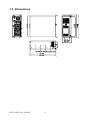
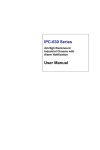
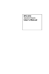
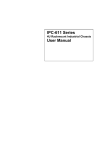
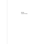
IPPC-4001 Series
5.7" VGA TFT LCD 4U 19" Rack
Industrial Panel PC with 14
Expansion Slots & Keyboard
Drawer
Users Manual
i
Copyright
This document is copyrighted, 2009, by Advantech Co., Ltd. All rights
are reserved. Advantech Co., Ltd. reserves the right to make improvements to the products described in this manual at any time without notice.
No part of this manual may be reproduced, copied, translated or transmitted in any form or by any means without the prior written permission of
Advantech Co., Ltd. Information provided in this manual is intended to
be accurate and reliable. However, Advantech Co., Ltd. assumes no
responsibility for its use, nor for any infringements upon the rights of
third parties which may result from its use.
All brand and product names mentioned herein are trademarks or registered trademarks of their respective holders.
Part No. 2003I400000
1st Edition
Printed in Taiwan
November 2009
IPPC-4001User Manual
ii
FCC Class A
Note: This equipment has been tested and found to comply with the limits
for a Class A digital device, pursuant to part 15 of the FCC Rules. These
limits are designed to provide reasonable protection against harmful
interference when the equipment is operated in a commercial environment. This equipment generates, uses, and can radiate radio frequency
energy and, if not installed and used in accordance with the instruction
manual, may cause harmful interference to radio communications. Operation of this equipment in a residential area is likely to cause harmful interference in which case the user will be required to correct the interference
at his own expense.
Additional Information and Assistance
Step 1. Visit the Advantech web site at www.advantech.com where you
can find the latest information about the product.
Step 2. Contact your distributor, sales representative, or Advantech's customer service center for technical support if you need additional
assistance. Please have the following information ready before
you call:
• Product name and serial number
• Description of your peripheral attachments
• Description of your software (operating system, version, application
software, etc.)
• A complete description of the problem
• The exact wording of any error messages
iii
Safety Instructions
1. Read these safety instructions carefully.
2. Keep this User's Manual for later reference.
3. Disconnect this equipment from any AC outlet before cleaning. Use a damp
cloth. Do not use liquid or spray detergents for cleaning.
4. For plug-in equipment, the power outlet socket must be located near the
equipment and must be easily accessible.
5. Keep this equipment away from humidity.
6. Put this equipment on a reliable surface during installation. Dropping it or letting it fall may cause damage.
7. The openings on the enclosure are for air convection. Protect the equipment
from overheating. DO NOT COVER THE OPENINGS.
8. Make sure the voltage of the power source is correct before connecting the
equipment to the power outlet.
9. Position the power cord so that people cannot step on it. Do not place anything
over the power cord.
10. All cautions and warnings on the equipment should be noted.
11. If the equipment is not used for a long time, disconnect it from the power
source to avoid damage by transient overvoltage.
12. Never pour any liquid into an opening. This may cause fire or electrical shock.
13. Never open the equipment. For safety reasons, the equipment should be
opened only by qualified service personnel.
14. If one of the following situations arises, get the equipment checked by service
personnel:
a. The power cord or plug is damaged.
b. Liquid has penetrated into the equipment.
c. The equipment has been exposed to moisture.
d. The equipment does not work well, or you cannot get it to work according
to the user's manual.
e. The equipment has been dropped and damaged.
f. The equipment has obvious signs of breakage.
15. DO NOT LEAVE THIS EQUIPMENT IN AN ENVIRONMENT WHERE
THE STORAGE TEMPERATURE MAY GO BELOW -20° C (-4° F) OR
ABOVE 60° C (140° F). THIS COULD DAMAGE THE EQUIPMENT. THE
EQUIPMENT SHOULD BE IN A CONTROLLED ENVIRONMENT.
16. CAUTION: DANGER OF EXPLOSION IF BATTERY IS INCORRECTLY
REPLACED. REPLACE ONLY WITH THE SAME OR EQUIVALENT
TYPE RECOMMENDED BY THE MANUFACTURER, DISCARD USED
BATTERIES ACCORDING TO THE MANUFACTURER'S INSTRUCTIONS.
The sound pressure level at the operator's position according to IEC 704-1:1982 is
no more than 70 dB (A).
DISCLAIMER: This set of instructions is given according to IEC 704-1. Advantech
disclaims all responsibility for the accuracy of any statements contained herein.
IPPC-4001User Manual
iv
Contents
Chapter
Chapter
1 General Information ....................................... 2
1.1
1.2
Introduction ....................................................................... 2
Specifications .................................................................... 2
1.3
1.4
1.5
IPPC-4001 Series List ....................................................... 4
Dimensions........................................................................ 4
Exploded Diagram............................................................. 5
1.6
Accessory Packing list ...................................................... 5
General ........................................................................... 2
System Hardware ........................................................... 3
Environment ................................................................... 3
Figure 1.1:Exploded Diagram ........................................ 5
2 System Setup.................................................... 8
2.1
2.2
2.3
2.4
Chapter
1.2.1
1.2.2
1.2.4
System Installation ........................................................... 8
2.1.1
2.1.2
2.1.3
2.1.4
2.1.5
Attaching the Handles .................................................... 8
Removing the Top Cover ............................................... 8
Chassis Front and Rear Sections .................................... 9
Drive Bay Installation .................................................. 11
Motherboard Installation & Information ..................... 11
LED Indicators ................................................................ 12
2.2.1
2.2.2
System Status LED ...................................................... 12
Power Status LED ........................................................ 13
Power Supply .................................................................. 13
Cooling Fan & Filter ....................................................... 14
3 Alarm Board .................................................. 16
3.1
3.2
3.3
3.4
Alarm Board Layout........................................................ 16
Alarm Board Specification.............................................. 17
Switch Setting ................................................................. 21
Thermal Sensor ............................................................... 22
v
IPPC-4001 User Manual
vi
CHAPTER
1
General Information
1
Chapter 1
Chapter 1 General Information
1.1 Introduction
The IPPC-4001 is a 4U height 14-slot rackmount IPC workstation with
5.7" LCD display and built-in slim keyboard and Touch Pad drawer. It is
designed as an all-in-one and cost-effective solution for traditional IPC
users. This IPPC-4001 includes a versatile 14-slot passive-backplane and
an optional power supply for different application inquiries, 10 function
and cursor keys for SI/VAR application programs, 2 front USB ports for
front accessible devices, a slim keyboard and touch pad drawer, and a
5.7" TFT LCD screen. The optional SNMP-1000, a fully integrated Rackmount IA Master, supports system fault detection. The web-enabled and
webbased alarm notification system monitors system status, including
SBC status, voltages, power supply, cooling fans and temperature through
web browser by minimizing system down time. A wide range of standard
computing peripherals from current Advantech IPC family can be integrated into the IPPC-4001 to meet different application development.
1.2 Specifications
1.2.1 General
• Certifications
BSMI, CCC, CE, FCC
• Cooling System 2 x 85 CFM fan w/Air Filter
• Dimensions (W x H x D)482 x 177 x 480 mm (19" x 7" x 18.9")
• Disk Drive Bay
3 x 5.25" (Front Accessible)
• Weight (Gross)
18 kg (39.6 lb)
• Power Input
90 ~ 264 VAC @ 47 ~ 63 Hz full range 6.0/3.0A
• Power Ouput
+5 V @ 30 A, +12 V @ 15 A, +3.3 V @ 28 A,
-5 V @ 0.3 A, -12 V @ 0.8 A, +5 VSB @ 2 A
• Power Supply
300 W, MTBF: 100,000 hrs
• Weight (Gross)
18 kg (39.7 lb)
IPPC-4001 User Manual
2
1.2.2 Passive Backplane
• Passive Backplane
PCA-6114P10
• Slots
2 PICMG, 10 PCI, 2 ISA
• Backplane Size
315 x 260 mm (12.4" x 10.24")
• PCI Bridge
Pericom PI7C8150MA
• PCI Slot
Primary 3 slots, Secondary: 7 slots
1.2.3 LCD Display
• Backlight Life
50,000 hrs (LED Backlight)
• Contrast Ratio
300 : 1
• Display Size
5.7"
• Display Type
QVGA TFT LCD
• Luminance
220 cd/m2
• Max. Colors
262 K (RGB 6-bit)
• Max. Resolution 640 x 480
• OSD Control
ON/OFF, Brightness down, up
• Viewing Angle (H/V°)140/100
1.2.4 Environment
• Humidity
10 ~ 85% RH @ 40° C (non-condensing)
• Operating Temperature 0 ~ 50° C (32 ~ 122° F)
• Storage Temperature
-20 ~ 60° C (-4 ~ 140° F)
• Vibration Protection
5 ~ 500 Hz, 1 GRMS random vibration
3
Chapter 1
1.3 Dimensions
IPPC-4001 User Manual
4
CHAPTER
2
System Setup
5
Chapter 2
Chapter 2 System Setup
2.1 System Installation
WARNING:
Before starting the installation process, be sure
to shut down all power from the chassis. Do this
by turning off the power switch, and unplugging
the power cord from the power outlet. When in
doubt, consult with an experienced technician.
2.1.1 Attaching the Handles
The handles for the front panel are in the accessory box. To install the
handles, simply secure them to the front panel with the provided screws.
2.1.2 Removing the Top Cover
First, remove the chassis cover.
The top cover is fixed to the chassis by two thumbscrews
To remove the top covers:
1. Release two thumbscrews on the rear upper location of the chassis.
2. Lift the cover.
2.1.3 Chassis Front and Rear Sections
The front panel switches behind the door are used for system power, system reset 1, system reset 2 (option), alarm reset and power switch. The
door cover is on the left side of the door cover, where the system LED status and key lock switch are located. The key can be found in the accessory
box as shown below.
The USB and PS/2 keyboard connectors are on the left of the front panel.
IPPC-4001 User Manual
6
System Reset 1: Press this switch to reinitialize the system. This is the
same as the hardware reset button. (Default setting)
System Reset 2: Press this switch to reinitialize the second system.
(Optional)
Alarm Reset Switch: Press this switch to suppress or stop an audible
alarm. Whenever a fault in the system occurs (e.g. fan failure, rising chassis temperature, backplane voltage problem), an audible alarm is activated.
Pressing this switch will cause the alarm to stop.
Power On/Off Switch: Use this switch to turn on/off the system power.
Momentary Switch: Use this switch and by way of ATX (PS_ON) function
to turn on system power. Please use system shutdown to turn off system
power automatic or press momentary switch for a while to turn off system
power
USB connector: If you have you want to connect any USB interface
device to the system, you could use this connector.
PS/2 connector: If you want to connect the PS/2 keyboard, you could use
this connector.
7
Chapter 2
2.1.4 Drive Bay Installation
The drive bay of IPPC-4001 can hold 5.25" (x3) devices.
Installation of disk drives:
1.
Remove the top cover
2.
Undo the two screws of cushion and four screws on the drive bay
3.
Lift off the Standard Drive Bay.
4.
Insert the drives into their proper locations in the drive bay and
secure them with the screws provided.
5.
Connect the disk drive power and signal cables.
2.2 LED Indicators
2.2.1 System Status LED
The System Status LED shows as follows:
When the PWR LED is RED, it indicates a redundant power supply failure. To stop the alarm buzzer, press the Alarm Reset button. Please check
out the redundant power supply right away and replace failure power supply module with a good one.
When the FAN LED is RED and blinking, it indicates a failing cooling fan.
An audible alarm is also activated. To stop the alarm buzzer, press the
Alarm Reset button then replace the fan immediately.
If the TEMP LED is RED and blinking, the system detects rising temperature inside the chassis. An audible alarm is activated. To stop the alarm
buzzer, press the Alarm Reset button. Inspect the rear section and fan filter immediately. Make sure airflow inside the chassis is smooth and not
blocked by dust or other particles.
IPPC-4001 User Manual
8
2.2.2 Power Status LED
Power Status LED indicates the status of the backplane voltage signals.
When a LED fails to light, it indicates a problem with one of the voltage
signals. An audible alarm is sounded. Check to make sure that the power
supply connector is properly attached to the backplane. If problem persists, consult an experienced technician.
2.3 Power Supply
IPPC-4001 supports PS/2 and redundant power supply both and without
any modifications.
9
Chapter 2
2.4 Cooling Fan & Filter
There are two cooling fans located inside the chassis. When one cooling
fan breaks down, the system sounds a continuous alarm. To disable the
alarm, press the Alarm Reset switch and replace the fan immediately. To
replace a defective fan, refer to the figures below. Press location A and
then pull B, the connector can then be released. If the filter is blocked
with dust, refer to the figure below for the filter replacement procedure.
B
A
IPPC-4001 User Manual
10
CHAPTER
3
Alarm Board
11
Chapter 3
Chapter 3 Alarm Board
The alarm board is located under the cooling fan section. It gives an
audible alarm when:
1.
Any power supply module of redundant power supply fails
2.
One of the cooling fans fai1s
3.
Temperature inside the chassis rises
4.
A problem occurs in one of the backplane voltage levels
The detailed layout and specification of the alarm board are as follows:
3.1 Alarm Board Layout
IPPC-4001 User Manual
12
3.2 Alarm Board Specification
Input Power: +5V, +12V
Input Signals:
• 7 FAN connectors (GND_+12V_FAN)
• One thermal board connector (up to 8 thermal boards in a roll)
• One power good input
• One alarm reset input.
• One voltage signal connector (connect from backplane, includes ±12V,
±5V, 3.3V)
• One ATX power connector (connect from CPU card)
• One system reset connector (connect from CPU card)
• One Hard Disk LED connector (connect from CPU card)
Output Signals:
• One LED board connector
• One LCM board connector
• SNMP daughter board connector (connect to SNMP-1000 mainboard)
• One Buzzer output
• ATX power connector (connect to chassis)
• System reset connector (connect to chassis)
Other Interfaces:
• One pair of Watch dog input/output signals
• One pair of I2C Bus signals (DATA and CLK)
• One LAN connector
• One COM connector
• One Battery pack connector
13
Chapter 3
Pin Definition
CN1 : External Power Connector, standard mini 4 Pin power connector
Pin 1 : +12V, 2A current maximum
Pin 2 : GND
Pin 3 : GND
Pin 4 : +5V, 2A current maximum
CN2 : 10/100M LAN Connector
Pin 1 : SPLED
TERMPLANE Pin 3 : RX+
Pin 2 :
Pin 4 : RX-
Pin 5 : GND
Pin 7 : TX+
Pin 9 : LILED
Pin 11 : N/A
Pin 6 : LVCC
Pin 8 : TXPin 10 : TERMPLANE
Pin 12 : NC
CN4 : I2C Sensor board (LM75) Connector
Pin 1 : +5V
Pin 2 : Sensor board I2C bus clock
Pin 3 : Sensor board I2C bus data
Pin 4 : GND
CN8 : RS-232 Connector
Pin 1 : DCD
Pin 2 : RX
Pin 3 : TX
Pin 4 : DTR
Pin 5 : GND
Pin 6 : DSR
Pin 7 : RTS
Pin 8 : CTS
Pin 9 : RI
Pin 10 : NC
Pin 11 : NC
Pin 12 : N/A
CN10 : LCM Display Board Connector
Pin 1 : LCM I2C bus data
Pin 2 : LCM I2C bus clock
Pin 3 : +12V
Pin 4 : GND
Pin 5 : +5V
Pin 6 : +5V
Pin 7 : Diagnostic LED
Pin 8 : GND
IPPC-4001 User Manual
14
CN11 : SNMP-1000 Daughter Board Connector (Left side)
Pin 1 : SIN
Pin 2 : SOUT
Pin 3 : CTS#
Pin 4 : DCD#
Pin 5 : RTS#
Pin 6 : DTR#
Pin 8 : ID 0
Pin 7 : DSR#
Pin 9 : ATX ON
Pin 10 : DO 4
Pin 11 : GND
Pin 12 : DO 3
Pin 13 : Watchdog IN
Pin 14 : DO 2
Pin 15 : Watchdog OUT
Pin 16 : DO 1
Pin 17 : SPLED
Pin 18 : NC
Pin 19 : LILED
Pin 20 : NC
Pin 22 : NC
Pin 21 : GND
Pin 23 : TX+
Pin 24 : NC
Pin 25 : TXPin 26 : NC
Pin 28 : NC
Pin 27 : RX+
Pin 30 : NC
Pin 29 : RXPin 31 : TERMPLANE
Pin 32 : NC
CN12 : SNMP-1000 Daughter Board Connector (Right side)
Pin 1 : NC
Pin 2 : NC
Pin 3 : Power Good A
Pin 4 : NC
Pin 5 : NC
Pin 6 : NC
Pin 7 : Diagnostic LED
Pin 8 : FAN 1
Pin 9 : GND
Pin 10 : FAN 2
Pin 11 : GND
Pin 12 : FAN 3
Pin 13 : VCC
Pin 14 : FAN 4
Pin 15 : VCC
Pin 16 : FAN 5
Pin 17 : VCC
Pin 18 : FAN 6
Pin 19 : BEEP
Pin 20 : FAN 7
Pin 21 : 5VSB
Pin 22 : NC
Pin 23 : -5V
Pin 24 : NC
Pin 25 : +5V
Pin 26 : B_SCLK
Pin 27 : +3.3V
Pin 28 : B_SDAT
Pin 29 : -12V
Pin 30 : T_SCLK
Pin 31 : +12V
Pin 32 : T_SDAT
15
Chapter 3
CN13 : Voltage Detect Input Connector
Pin 1 : 5VSB
Pin 2 : GND
Pin 3 : GND
Pin 4 : -5V
Pin 5 : +5V
Pin 6 : +3.3V
Pin 7 : -12V
Pin 8 : +12V
CN16 : 4 bit Power Good Input,
Pin 1 : Power GOOD A
Pin 2 : GND
CN18 : LED Board Connector
Pin 1 : GND
Pin 3 : +12V Signal
Pin 5 : -12V Signal
Pin 7 : Power Good Signal
Pin 9 : Temperature Good Signal
Pin 11 : Fan Good Signal
Pin 13 : NC
Pin 15 : 5VSB Signal
Pin 2 : +5V Signal
Pin 4 : -5V Signal
Pin 6 : HDD Signal
Pin 8 : Power Fail Signal
Pin 10 : Temperature Fail Signal
Pin 12 : FAN Fail Signal
Pin 14 : +3.3V Signal
CN19 : Connector bank from CPU card
Pin 1 : HDD LED Signal
Pin 2 : ATX soft power switch
Pin 3 : I2C Clock
Pin 4 : ATX soft power switch(-)
Pin 5 : I2C Data
Pin 6 : System Reset Signal
CN20 : Connector bank to Chassis
Pin 1 : ATX Momentary switch
Pin 3 : GND
Pin 5 : Watch Dog IN
J1 : External Speaker
Pin 1 : Buzzer
IPPC-4001 User Manual
16
Pin 2 : ATX Momentary switch(-)
Pin 4 : System Reset Signal
Pin 6 : Watch Dog OUT
Pin 2 : +5V
3.3 Switch Setting
Fan Number Setting
Thermal Board Temperature Setting
17
Chapter 3
IPPC-4001 User Manual
18