1
Catalogue Building Services
Heating,
Air-conditioning,
Cooling
Pumps, pump systems and
accessories for heating,
secondary hot water,
air-conditioning and cooling
International edition 2011/2012 - 50 Hz
Y
Y
Y
UJBFXEOKZRUFOE@EEVRWWR@UE`\E
{jjq{|
j{jq¡¢jq|j
j{|jxxjqj
{
j£jqjq|xxq|
`bjkqxxq{|j}~j{j|j
q|
j{
jjjq|j``j{j{jj
|q{jqj|{j|
j{j{}j{|qq{|
jj
qj
q|j
xq{|jj{j`j{jjj{q
q{|jj``jxj`j?@BEFBJKLJBEOQOLKRUKVRWRLXYEZRORLE[[[\[RW@\]@^_`J
APPLIES TO
EUROPEAN
DIRECTIVE
FOR ENERGY
RELATED
PRODUCTS
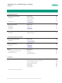
Contents
General notes and abbreviations
9
11
Heating, air-conditioning, cooling
46
Heating, air-conditioning,
cooling
Planning guide
Wilo-Stratos PICO, Stratos, Stratos-D, TOP-E, TOP-ED, Smart
Wilo-Star-RS, Star-RSD, TOP-RL, TOP-S, TOP-SD, TOP-D
Wilo-Stratos GIGA, VeroLine-IP-E, VeroTwin-DP-E, CronoLine-IL-E,
Wilo-CronoTwin-DL-E, Veroline-IPL, VeroTwin-DPL, CronoLine-IL,
Wilo-CronoTwin-DL
Secondary hot water
314
366
Solar thermal, geothermal,
systems
Solar thermal, geothermal energy, systems
Secondary hot water
Wilo-Star-Z NOVA, Stratos ECO-Z, Stratos-Z, Stratos-ZD
Wilo-Star-Z, Star-ZD, TOP-Z, VeroLine-IP-Z
Wilo-Stratos ECO-ST, Star-ST, Star-RSG
Wilo-Safe
Wilo-DrainLift Con, DrainLift Con Plus
Accessories
379
Accessories
Pipe unions, adapter fittings
Thermal insulation for pumps
Pump cold water insulation
Service units
397
454
Switchgears and control
devices / pump management
Switchgears and control devices
Pump management
Wilo-S1R-h, SK, VR-HVAC, CRn, CC-HVAC
Wilo-Protect-Module-C
Wilo-IF-Modules
Building automation
Wilo Building Services catalogue – 50 Hz – Heating, air-conditioning, cooling – Edition 2011/2012 – Subject to change without prior notice
3
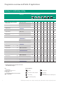
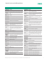
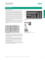
Programme overview and fields of applications
Heating, air-conditioning, cooling
Pump type
Main field of application
Page
Heating, air-conditioning, cooling
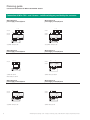
Glandless high-efficiency pumps
- Single pumps
Wilo-Stratos PICO
S/M
–
S/M
S/M
–
–
–
50
Wilo-Stratos
M/C
–
–
C
M/C
–
–
58
- Double pumps
Wilo-Stratos-D
C
–
–
C
C
–
–
80
Energy-saving pumps
- Single pumps
Wilo-TOP-E *)
M/C
–
–
–
–
–
–
47
– Double pumps
Wilo-TOP-ED *)
C
–
–
–
–
–
–
47
Automatic pumps
– Single pumps
Wilo-Smart
S/M
–
S/M
S
–
–
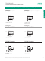
Glandless standard pumps
- Single pumps
Wilo-Star-RS
S/M
–
S/M
S/M
–
–
–
101
- Double pumps
Wilo-Star-RSD *)
S/M
–
–
S/M
–
–
–
48
- Single pumps
Wilo-TOP-RL *)
M/C
–
–
C
–
–
–
49
M/C
–
–
C
–
–
–
113
(maximum 2660 rpm)
Wilo-TOP-S (max. 2880 rpm)
92
- Double pumps
Wilo-TOP-SD (max. 2880 rpm)
C
–
–
C
–
–
–
152
- Single pumps
Wilo-TOP-D *) (max. 1400 rpm)
M/G
–
–
G
–
–
–
49
Glanded high-efficiency pumps
- Single pumps
/
Wilo-Stratos GIGA
M/C
–
–
M/C
–
–
–
214
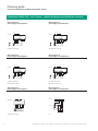
Glanded energy-saving pumps
- Single pumps
/
/
/
/
Wilo-VeroLine-IP-E
M/C
–
–
M/C
–
–
–
224
Wilo-VeroTwin-DP-E *)
M/C
–
–
M/C
–
–
–
207
Wilo-CronoLine-IL-E
M/C
–
–
M/C
–
–
–
240
Wilo-CronoTwin-DL-E *)
M/C
–
–
M/C
–
–
–
208
/
/
/
/
Wilo-Veroline-IPL
M/C
–
–
M/C
–
–
–
270
Wilo-VeroTwin-DPL *)
M/C
–
–
M/C
–
–
–
209
Wilo-CronoLine-IL
M/C
–
–
M/C
–
–
–
287
Wilo-CronoTwin-DL *)
M/C
–
–
M/C
–
–
–
210
- Double pumps
- Single pumps
- Double pumps
Glanded standard pumps
- Single pumps
- Double pumps
- Single pumps
- Double pumps
*) Detailed information on these products can be found
in the Wilo Online Catalogue.
Key:
S
M
C
Fields of application:
Not applicable
Single- and two-family houses
Multi-family houses
Commercial
New in the programme or series extension
or modification
Heating
Solar thermal
Secondary hot water circulation
Geothermal
Floor heating
Condensate
Condensing boilers/air-conditioning units
Air-conditioning/cooling
4
Wilo Building Services catalogue – 50 Hz – Heating, air-conditioning, cooling – Edition 2011/2012 – Subject to change without prior notice
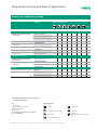
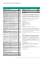
Programme overview and fields of applications
Heating, air-conditioning, cooling
Main field of application
Heating, air-conditioning,
cooling
Pump type
Page
Glandless high-efficiency pumps
- Single pumps
Wilo-Star-Z NOVA
–
S
–
–
–
–
–
317
Wilo-Stratos ECO-Z
–
M
–
–
–
–
–
321
Wilo-Stratos-Z
–
M/C
M/C
C
M/C
–
–
325
- Double pumps
Wilo-Stratos-ZD *)
C
–
–
C
C
–
C
315
Glandless standard pumps
- Single pumps
Wilo-Star-Z
–
S/M
M
–
–
–
–
334
- Double pumps
Wilo-Star-ZD *)
–
S/M
M
–
–
–
–
315
- Single pumps
Wilo-TOP-Z
–
M/C
M/C
–
–
–
–
344
Glanded standard pumps
- Single pumps
Wilo-VeroLine-IP-Z
M/C
M/C
M/C
M/C
–
–
–
362
Wilo-Stratos ECO-ST *)
–
–
–
–
S/M
–
–
366
Wilo-Star-ST *)
–
–
–
–
S/M
–
–
366
Wilo-Star-RSG *)
–
–
–
–
–
S/M
S/M
366
System separation for floor heating
Wilo-Safe
–
–
S/M
–
–
–
Condensate lifting units
Wilo-DrainLift Con
–
–
–
–
–
–
S/M/C
371
Wilo-DrainLift Con Plus
–
–
–
–
–
–
S/M/C
375
Sanitary hot water
Secondary hot water
Glandless high-efficiency pumps
- Single pumps
Glandless standard pumps
- Single pumps
Solar thermal, geothermal,
systems
Solar thermal, geothermal
Systems
Accessories
/
368
*) Detailed information on these products can be found
in the Wilo Online Catalogue.
S
M
C
Fields of application:
Not applicable
Single- and two-family houses
Multi-family houses
Commercial
New in the programme or series extension
or modification
Heating
Solar thermal
Secondary hot water circulation
Geothermal
Floor heating
Condensate
Condensing boilers/air-conditioning
units
Switchgears and control
devices / pump management
Key:
Air-conditioning/cooling
Wilo Building Services catalogue – 50 Hz – Heating, air-conditioning, cooling – Edition 2011/2012 – Subject to change without prior notice
5
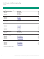
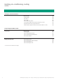
Heating, air-conditioning, cooling
Contents
Heating, air-conditioning, cooling
Glandless high-efficiency pumps
Single pumps
Double pumps
Energy-saving pumps
Series overview
Wilo-Stratos PICO
46
50
Wilo-Stratos
58
Wilo-Stratos-D
80
Series overview
47
Single pumps
Wilo-TOP-E
*)
Double pumps
Wilo-TOP-ED
*)
Automatic pumps
Series overview
47
Single pumps
Glandless standard pumps
Wilo-Smart
92
Series overview
48
Single pumps
Wilo-Star-RS
101
Double pumps
Wilo-Star-RSD
Single pumps
Wilo-TOP-RL
*)
*)
Wilo-TOP-S
113
Double pumps
Wilo-TOP-SD
152
Single pumps
Wilo-TOP-D
Glanded high-efficiency pumps
Single pumps
Glanded energy-saving pumps
Single pumps
Series overview
Wilo-Stratos GIGA
Series overview
Wilo-VeroLine-IP-E
*)
206
214
207
224
Double pumps
Wilo-VeroTwin-DP-E
*)
Single pumps
Wilo-CronoLine-IL-E
240
Double pumps
Wilo-CronoTwin-DL-E
Glanded standard pumps
Series overview
Single pumps
Wilo-Veroline-IPL
Double pumps
Wilo-VeroTwin-DPL
Single pumps
Wilo-CronoLine-IL
Double pumps
Wilo-CronoTwin-DL
*)
209
270
*)
287
*)
*) see series overview or Wilo online catalogue
6
Wilo Building Services catalogue – 50 Hz – Heating, air-conditioning, cooling – Edition 2011/2012 – Subject to change without prior notice
Heating, air-conditioning, cooling
Contents
Single pumps
Double pumps
Glandless standard pumps
Series overview
314
Wilo-Star-Z NOVA
317
Wilo-Stratos ECO-Z
321
Wilo-Stratos-Z
325
Wilo-Stratos-ZD
*)
Series overview
315
Single pumps
Wilo-Star-Z
334
Double pumps
Wilo-Star-ZD
Single pumps
Wilo-TOP-Z
344
Series overview
316
Glanded standard pumps
Single pumps
Wilo-VeroLine-IP-Z
*)
Sanitary hot water
Glandless high-efficiency pumps
Heating, air-conditioning,
cooling
Secondary hot water
362
Solar thermal, geothermal, systems
Single pumps
Glandless standard pumps
Single pumps
Systems
Series overview
Wilo-Stratos ECO-ST
Series overview
366
*)
Solar thermal, geothermal,
systems
Glandless high-efficiency pumps
366
Wilo-Star-ST
*)
Wilo-Star-RSG
*)
Series overview
367
System separation for floor heating
Wilo-Safe
368
Condensate lifting units
Wilo-DrainLift Con
371
Wilo-DrainLift Con Plus
375
379
Adapter fittings Wilo-(R), Wilo-(RF), Wilo-(F)
381
Thermal insulation for pumps
385
Pump cold water insulation
386
Service units
388
Wilo-IR-Monitor
391
Wilo-IR-Modul
393
Switchgears and control
devices / pump management
Pipe unions
Accessories
Accessories
*) see series overview or Wilo online catalogue
Wilo Building Services catalogue – 50 Hz – Heating, air-conditioning, cooling – Edition 2011/2012 – Subject to change without prior notice
7
Heating, air-conditioning, cooling
Contents
Switchgears and control devices
Series overview
397
Planning guide
399
Wilo-S1R-h
406
Wilo-SK 601
407
Wilo-SK 602, Wilo-SK 622
408
Control systems Wilo-VR-HVAC, Wilo-CRn, Wilo-CC-HVAC
421
Signal transmitters and accessories Wilo-CRn
432
Option modules, signal transmitters and accessories Wilo-CC-HVAC
436
Pump management Wilo-Control
Pump control
Building automation (BA)
Series overview
454
Planning guide
462
Wilo-IF-Modules Wilo-Stratos
467
Wilo-IF-Modules Wilo glanded pumps
486
Wilo-Protect-Module
492
Wilo-Control AnaCon
497
Wilo-Control DigiCon, DigiCon-Modbus
499
Wilo-Control DigiCon-A
501
Wilo-Control DigiCon-LBF
503
*) see series overview or Wilo online catalogue
8
Wilo Building Services catalogue – 50 Hz – Heating, air-conditioning, cooling – Edition 2011/2012 – Subject to change without prior notice
General notes and abbreviations
Abbreviation
Meaning
1~
1-phase current
Abbreviation
Meaning
3-phase current
LON
Automatic adjustment of pump performance during
setback phases, e.g. boiler setback operation overnight
Local Operating Network (open data bus system,
standardised and independent of any single manufacturer, in LONWorks networks)
3~
Autopilot
Modbus
Communication protocol based on a master/slave architecture. Ethernet and RS485 are used as the media
of transmission. Widespread in industrial and building automation applications.
mmol/l
Millimols per litre; SI unit for assessing water hardness (total hardness, or concentration of alkaline
earth ions)
MOT
Motor module (drive motor + impeller + terminal box/
electronics module) for replacement
P1
Power consumption (power supplied from the network)
PELV
Protective Extra Low Voltage; PELV provides extra
protection from electric shock, like SELV. The voltage
is so low that current flowing through the human
body normally does no harm. However, unlike SELV,
active parts and components of the equipment must
be earthed and connected with the protective earth
conductor.
PLR
Pump master computer, Wilo-specific data interface
Q (=)
Volume flow
RMOT
Spare motor (drive motor + impeller + terminal box/
electronics module) for replacement
SBM
Run signal or collective run signal
SELV
Safety Extra Low Voltage; SELV (formerly “safety low
voltage”) is a low electrical voltage that offers extra
protection against electric shocks compared to electric circuits with higher voltages due to the low voltage level and the insulation. The voltage is so low
that electrical shock currents are normally not dangerous.
SSM
Fault signal or collective fault signal
Control input, 0 - 10 V
Analogue input for external control
Wilo-Control
Building automation management with pumps and
accessories
blsf
Blocking current-proof, no motor protection
required
DM
Three-phase motor, 3~
DN
Nominal diameter of the flange connection
p
Differential pressure
p-c
Control mode for constant differential pressure
p-T
Control mode for differential pressure control
depending on the fluid temperature
p-v
Control mode for variable differential pressure
T
Control mode for differential temperature
BACnet
Internationally defined company-neutral standard
for data communication in building automation
systems (ISO 16484-5).
CAN
CAN (Controller Area Network) - Multi master bus
system, in which several equal CAN-devices may
communicate via a 2-core bus within very short cycle
times. The Wilo-CAN bus includes a CANopen Standard (EN 50325-4) which is independent of the
supplier.
EBM
Individual run signal
EM
Single-phase motor, 1~
ESM
Individual fault signal
EnEV
German Energy Conservation Legislation
ECM technology
Electronically commutated motor with new wet rotor
encapsulation, newly developed glandless drive concept for high-efficiency pumps
Ext. Off
“Overriding Off” control input
Ext. Min
Control input “Overriding Min”, e. g. for setback
operation without Autopilot
FI
Residual current-operated protective device
BA
Building automation
GRD/GLRD
Mechanical seal
TrinkwV
2001
German Drinking Water Ordinance of 2001
(valid from 01.01.2003)
°dH
Degree of German water hardness; replaced by the
SI unit mmol/l; conversion 1 °dh = 0.1783 mmol/l
VDI 2035
VDI guideline for preventing damage in hot-water
heating installations
H
Delivery head
IF
Interface
WRAS
Water Regulations Advisory Scheme (potable water
approval for Great Britain and Northern Ireland)
Int. MS
Internal motor protection: pumps with internal protection against unacceptably high winding temperatures
WSK
Thermal winding contacts (in motor for monitoring
the winding temperature, full motor protection
through additional tripping unit)
IR
Infrared interface
KDS
Capacitor
Operating mode of double pumps: Individual operation of the respective duty pump
KLF
PTC thermistor sensor
Operating mode of double pumps: Parallel operation
of both pumps
Cataphoretic coating
Cataphoretic coating (electrophoretically deposited
paint, EDP): paintwork with high adhesive strength
for long-lasting corrosion protection
Number of poles of electric motors:
2-pole motor = approx. 2900 rpm at 50 Hz
KTW
Approval for products with plastics, for utilisation in
potable water applications
Number of poles of electric motors:
4-pole motor = approx. 1450 rpm at 50 Hz
Number of poles of electric motors:
6-pole motor = approx. 950 rpm at 50 Hz
Wilo Building Services catalogue – 50 Hz – Heating, air-conditioning, cooling – Edition 2011/2012 – Subject to change without prior notice
9
General notes and abbreviations
10
Material
Meaning
AISI
Material
Meaning
AISI
1.4021
Chromium steel X20Cr13
420
V2A
Material group, e.g. 1.4301, 1.4306
304
1.4034
Chromium steel X46Cr13
V4A
Material group, e.g. 1.4404, 1.4571
316
1.4057
Chromium steel X17CrNi16-2
1.4122
Chromium steel X39CrMo17-1
1.4301
Chromium-nickel steel X5CrNi18-10
1.4305
Chromium-nickel steel X8CrNiS18-9
303
1.4306
Chromium-nickel steel X2CrNi19-11
304L
1.4401
Chromium-nickel-molybdenum steel
X5CrNiMo17-12-2
316
1.4408
Chromium-nickel-molybdenum steel
GX5CrNiMo19-11-2
316
1.4462
Chromium-nickel-molybdenum steel
X2CrNiMoN22-5-3
329
(2205)
1.4541
Chromium-nickel steel with titanium
addition X6CrNiTi18-10
321
1.4542
Chromium-nickel steel with copper and
630
niobium additions X5CrNiCuNb16-4
1.4571
Chromium-nickel steel with titanium
addition X6CrNiMoTi17-12-2
Abrasite
Chilled cast iron material for use in
strongly abrasive fluids
Al
Light metal material (aluminium)
Ceram
Coating with very high adhesive
strength for long-lasting corrosion protection
Composite
High-strength plastic material
EN-GJL
Cast iron with lamellar graphite, also referred to as grey cast iron. The use of
grey cast iron in domestic water systems is governed by the Drinking Water
Directive 98/83/EC and applicable recognised technical rules and standards!
431
Wear and tear
304
316Ti
Pumps or parts of pumps are subject to wear in accordance with
state-of-the-art technology (DIN 31051/DIN-EN 13306). This wear
may vary depending on operating parameters (temperature, pressure,
speed, water conditions) and the installation/usage situation and may
result in the malfunction or failure at different times of the aforementioned products/components, including their electrical/electronic circuitry.
Wearing parts are all components subject to rotary or dynamic stress,
including electronic components under tension, in particular:
• Seals (including mechanical seals), seal rings
• Stuffing boxes
• Bearings and shafts
• Impellers and pump components
• Wear rings and counter rings
• Stationary wear rings / wear plates
• Macerator
• Capacitor
• Relays / contactors / switches
• Electronic circuits, semiconductor components, etc.
Pumps and continuous-flow machines (like submersible mixers and
recirculation pumps), as well as their components with coatings
(cataphoresis coating, 2K- or Ceram-coating) are subject to constant
wear due to the abrasive fluid contents. For this reason the coating is
also among the wearing parts of these units.
We do not accept any liability for faults or defects arising from natural wear and tear.
Note
In accordance with German Energy Saving Ordinance [Energieeinspar-Verordnung EnEV] as of the 1.2.2002 at boiler outputs from
25 kW, heating pumps are to be equipped with switchgears for automatic performance control or electronically controlled pumps are to
be installed.
In accordance with TrinkwV 2001 and DIN 50930-6, only circulating
pumps with corrosion-resistant pump housings made of stainless
steel or red brass (CC 499K) are to be utilized in secondary hot water
circulation systems.
EN-GJS
Cast iron with spheroidal graphite, also
referred to as spheroidal cast iron. The
use of spheroidal cast iron in domestic
water systems is governed by the
Drinking Water Directive 98/83/EC and
applicable recognised technical rules
and standards!
G-CuSn10
Zinc-free bronze
GfK
Fibreglass plastic
GG
See EN-GJL
GGG
See EN-GJS
Detailed information on the subject of “Replacing heating pumps”
can be found in the current Wilo replacement guide for heating
pumps.
GJMW
Special cast iron: white malleable cast
iron (former designation: GTW)
Wilo – General Terms of Delivery and Service
Inox
Stainless steel
NiAl-Bz
Nickel-aluminium bronze
The latest version of our General Terms of Delivery and Service can be
found on the Internet at
PPO
Trade name: Noryl, fibreglass-reinforced plastic
PP-GF30
Polypropylene, reinforced with 30%
fibreglass
PUR
Polyurethane
SiC
Silicon carbide
St
Steel
Pump replacement
www.wilo.com/agb
Wilo Building Services catalogue – 50 Hz – Heating, air-conditioning, cooling – Edition 2011/2012 – Subject to change without prior notice
Planning guide
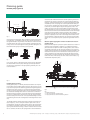
Glandless pumps (general)
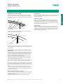
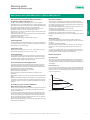
Circulation pumps should always be selected so that the specified
duty point is located at or as near as possible to the point of maximum efficiency (optimum volume flow) of the maximum speed H/Q
pump curve.
ma
x. (
min
. (3
1
)
(2
)
)
Optimal flow rate
Fig.: Pump curve
Circulation pipe
Wilo recommends the installation of a check valve in order to prevent
faulty circulation and to prevent gravity circulation in pumps that
have been shut down.
Heating, air-conditioning,
cooling
Pump selection: General remarks
Variable speed control
Experience shows that variable speed control is only required in circulation pumps in secondary hot water circulation systems for the
basic adjustment of the performance. An automatic speed control is
not required. A time-dependent activation/deactivation should however be provided for each installation.
Motor protection
Blocking current-proof pumps and pumps with internal protection
against unacceptably high winding temperatures do not require motor protection. All other pumps have integrated full motor protection
including trip electronics or full motor protection (WSK) in conjunction with an external tripping unit.
If the specified duty point lies between two pump curves, then the
smaller pump is always to be selected:
max. 1
A
Duty point
max. 2
B
Flow rate
Fig.: Pump selection
The resulting volume flow reduction has no appreciable effect on the
actual heating output in heating systems. This applies to pumps for
cooling systems.
Pump selection: Secondary hot water circulation systems
Pump selection
• In order to ensure the correct configuration of the secondary hot water circulation system, the pipe system must be designed in accordance with DIN 1988 as well as DVGW worksheets W 551 to W 553.
• The volume flow should be determined according to the specifications in the standard and the DVGW guideline.
• If the hydraulic duty point is between two pump curves, then the
next largest circulation pump or speed stage is to be selected in accordance with DVGW worksheet W 553.
• The heat losses in the ascending and circulation secondary hot water
pipes are to be reduced to a minimum by appropriate insulation.
Since most secondary hot water circulation systems permit periodic
circulation pump deactivation (as a rule at night), a clock timer should
be included in the standard equipment for automatic ON/OFF operation.
The German energy savings ordinance (EnEV) demands periodic
pump activation/deactivation. Legionellae switching of the heat generator or the heating controller are to be observed and taken into account during programming.
Maximum secondary hot water temperature
In view of the hardness-forming components contained in the water,
secondary hot water circulation systems should not be operated at
temperatures above 65 °C.
This limit is required to avoid the formation of lime deposits.
Wilo Building Services catalogue – 50 Hz – Heating, air-conditioning, cooling – Edition 2011/2012 – Subject to change without prior notice
11
Planning guide
Glandless pumps (general)
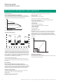
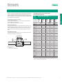
Pump duty splitting
Flow rates in pipe and pump
General notes on double pumps
• Two pump heads mounted in a common housing, hydraulically separated by a switchover valve
• Specific design characteristics like with corresponding single pump
series
• Replacement of an equally powerful single pump with identical installation dimensions
• Wide range of applications due to standard 3-stage switching
The flow rate of the fluid in the pipework is determined by the crosssection sizes. The values listed below should not be exceeded:
Nominal connection diameter DN Flow rate v [m/s]
[Ø mm]
In building installations
Up to Rp 1¼ or DN 32
DN 40 and DN 50
DN 65 and DN 80
DN 100 and greater
In long-distance heating pipes
Up to 1.2
Up to 1.5
Up to 1.8
Up to 2.0
2.5 to a maximum of 3.5
Pump duty splitting
Splitting the assigned maximum design output to a double pump in
parallel operation enables - particularly in terms of heating - significantly improved adaptability to partial-load conditions and optimum economic efficiency. The partial-load pump output to be
achieved on average during the season, i.e. for more than 85% of the
heating season is sufficient for the operation of one pump only; the
second pump is available for parallel operation for occasional fullload requirements.
The flow rates [m/s] in the pump are specified in all duty charts for
Wilo pumps as a function of the pump output.
Benefits of splitting the output between two pumps:
Viscous fluids
• Reduction of the operating costs by between 50% and 70%
• Increased reliability due to the constant availability of a standby unit
ready for operation
The individual performance maps for double pumps featured in the
relevant chapters specify the hydraulic performance values for both
individual and parallel operation.
Operating modes for double pumps
Double pumps are suitable for operation in either of two basically different operating modes:
• Main/standby mode
• Parallel operation
All pump curves included in the catalogue apply to the pumping of
water (kinematic viscosity = 1 mm2/s). If fluids of different density
and/or viscosity are pumped (e.g. water-glycol mixtures), the hydraulic values of the pump and the pipe system will deviate. Documents on the calculation of the correction values for the selection
of the pumps can be obtained from Wilo.
Correction values for the pipe system (increased pressure loss, specific thermal output deficit) cannot be provided by the pump manufacturer. They must be calculated by the planning engineer in cooperation with the chemical additive suppliers and the manufacturers of
the valves.
Minimum inlet pressure for the prevention of cavitation
12
Main/standby mode
(RESERVE)
Parallel operation
(ADDITION)
Pump I or Pump II in operation
Both pumps in operation
The version-specific pump output is provided by whichever one
of the two pumps is acting as the
main pump; the second pump remains on standby, ready for timeor fault-actuated switchover.
The version-specific pump output is provided by both pumps
operating in parallel. One pump
can be switched off during partial-load operation.
To prevent cavitation (vapour bubble formation within the pump), it
is necessary to maintain a sufficiently high over pressure (suction
head) at the pump suction port in relation to the vapour pressure of
the fluid being pumped.
The minimum suction heads are listed in the respective tables for
all glandless pumps. These guidance values apply for heating systems up to 110 °C/130 °C feed temperature and installation location up to 300 m above sea level. Addition for higher altitudes:
0.1 m/100 m height increase.
The values must be increased accordingly when pumping fluids of
higher temperatures or lower densities, where there is greater flow
resistance on the pump suction side, and in regions of lower atmospheric pressures.
Wilo Building Services catalogue – 50 Hz – Heating, air-conditioning, cooling – Edition 2011/2012 – Subject to change without prior notice
Planning guide
Notes on installation and operation
Connections
Permitted ambient temperature: 0 °C to +40 °C
Screw-end pumps
Screw-end pumps are equipped with connecting threads in accordance with DIN EN ISO 228, Part 1. Seals are included in the scope of
delivery.
Pipe unions with pipe thread in accordance with DIN EN 10226-1
must be ordered separately.
Installation
Installation inside a building
Glandless pumps must be installed in dry, well-ventilated, frost-free
rooms.
Installation outside a building (outdoor installation)
The glandless pumps of the following series are suitable for outdoor
installation:
• Wilo-Stratos/-D
• Wilo-TOP-S/-SD
• Wilo-TOP-RL
The following conditions must be complied with:
• Installation of the pump in a sump (e.g. light sump, ring sump) with
cover or in a cabinet/housing for protection against the weather
• Avoidance of direct sunlight on the pump
• Protection of the pump against rain. Dripping water from above is
permitted provided that the electrical connection has been established in accordance with the installation and operating instructions
and the terminal box has been properly sealed
• Provide adequate ventilation/heating in situations where the permitted ambient temperature is exceeded or fallen short of
• Permissible ambient temperature for outdoor installation:
Stratos/-D:
TOP-S/-SD:
TOP-RL:
-10 °C to +40 °C
-20 °C to +40 °C
-20 °C to +40 °C
Condensation water
All standard pumps for cold water operation that are intended for applications up to -10 °C/-20 °C are fully condensation-proof. The grey
cast iron pump housing of the following series is used for surface finishing:
• Stratos/Stratos-D
• TOP-S/-SD
• TOP-D
with a special coating (KTL: (cataphoretic coating).
The benefits of this coating are:
• Optimum corrosion protection against condensation formation on
the pump housings in cold-water installations
• Very high scratch and impact resistance
Intermittent operation
The series
• Stratos/Stratos-D/Stratos-Z/Stratos-ZD
• Stratos PICO/ECO
• Star-RS/RSD
• TOP-S/-SD
• TOP-D
• TOP-Z
can also be used for intermittent operation.
Heating, air-conditioning,
cooling
Glandless pumps (general)
DIN 2999 (pipe thread sealing DIN EN ISO 228/1
in the thread)
(sealing pipe thread with flat gasket
on longitudinal side)
Female pipe thread Rp 1½
Male pipe thread R 1½
Female pipe thread G 1½
Male pipe thread G 1½
Flange-end pumps
The pump flanges are designed in accordance with DIN 2531,
DIN 2533 or DIN EN 1092-2. Detailed information is provided for the
respective pump series.
Combination flange pumps
Flange-end pumps with combination flanges can be mounted with
counter flanges PN 6 and PN 16 in accordance with DIN or DIN EN up
to and including DN 65. The installation of a combination flange with
a combination flange is not permitted. Screws with a tensile strength
class of 4.6 or higher must be used for the flanged connections. The
washers included in the scope of delivery must be fitted between
heads of the screws/nuts and the combination flange.
Recommended screw lengths:
Thread
Tightening
torque
Flange connection PN 6
M12
40 Nm
Flange connection PN 10
M16
95 Nm
Minimum screw length
DN 32/DN 40
DN 50/DN 65
55 mm
60 mm
60 mm
65 mm
Motor
Glandless pump motors with protection class:
• Wilo-Stratos series
• Wilo-Star series
• Wilo-TOP range
• Remaining pump range
• Insulation class
• Emitted interference
• Interference resistance
44
44
44
IP 42
F/H
EN 61000-6-3
EN 61000-6-2
Electrical connection
• All Wilo pumps are made for a voltage of 230 V or 400 V
Operating pressure
The maximum system pressure (operating pressure) and the flange
versions for the pumps are listed in the relevant tables. All flanges on
glandless pumps (except Stratos, Stratos-Z, Stratos-D and
Stratos-ZD) have pressure-measurement connections R 1/8
(tolerance ±10%) in accordance with DIN IEC 60038.
• All Wilo pumps made after 1 January 1995 have been labelled with
the CE marking in accordance with the EU Machinery Directive.
• When pumps are used in systems with fluid temperatures above
90 °C, a suitably heat-resistant connecting pipe must be used.
Wilo Building Services catalogue – 50 Hz – Heating, air-conditioning, cooling – Edition 2011/2012 – Subject to change without prior notice
13
Planning guide
Glandless pumps (general)
Electronic performance control
Heating pumps are, due to their high annual operating hours, among
the largest power-consuming appliances in buildings.
Automatic pump performance control helps drastically to reduce
power consumption in heating pumps. Reductions of up to 50% can
thus be achieved. Compared to standard pumps, high-efficiency
pumps can even save up to 80% electricity costs.
All operating states, in particular in the partial load range that is typical for heating systems, can be optimised hydraulically by means of
automatic pump performance control.
A further significant effect connected with the prevention of a rise in
pump pressure is the avoidance of flow noise in thermostatic valves.
Installations with long cable lengths (l > 10 m) between converter
and motor may increase the du/dt and û levels (resonance). The same
applies to operation with more than 4 units using a common power
supply. The output filters must be designed by the manufacturer of
the frequency converter or the filter supplier. If losses in the motor
are caused by the frequency converter, the pumps are to be run at a
maximum of 95 % of their nominal speed. If glandless pumps of the
TOP-S/-SD, TOP-D and TOP-Z series are operated on one frequency
converter, the following limit values at the connection terminals of
the pumps must not be fallen short of:
Umin = 150 V
fmin = 30 Hz
German Energy Savings Ordinance, EnEV
Minimum volume flow
In the context of the legal measures for the reduction of
CO2emissions, with regard to the electricity consumption of heating
circulation pumps, the legislator has stipulated in the EnEV (as
amended on October 1, 2009) that circulation pumps in central heating system with a nominal thermal output exceeding 25 kW must be
equipped in such a way that the electrical power consumption is automatically adjusted to the specific pumping operation requirements
in at least three stages.
Even though the EnEV does not demand the use of an automatic
pump output controller for pumps with a nominal thermal output below 25 kW, it is nevertheless the case that by far the greater potential
savings in terms of electricity and CO2 are to be found in the oneand two-family house sector, i.e. with installations below 25 kW.
The pump output controller does not replace the need for the correct
dimensioning of the circulation pump. The installed pump output
must also be checked when the pump is replaced. Controlled pumps
that are slightly overdimensioned do not pose any risk if they are correctly set to the nominal load requirement.
Larger pumps require a minimum flow rate to ensure trouble-free operation. Operating against a closed slide valve, volume flow
Q = 0 m3/h, can lead to overheating inside the pump.
Standards/directives
• CE marking (all Wilo pumps)
• Certification according to:
- DIN EN ISO 9001.
- DIN EN ISO 14001
Pump curves
The pump curves apply to water at +20°C and a kinematic viscosity of
1 mm2/s.
The pump curves take the European voltages of 230 V and 400 V into
account.
• Limit conditions for pump operation at Q = 0 m3/h:
up to P2 = 1 kW are unproblematic if the fluid temperature is 10 K
below the maximum permissible fluid temperature.
• Above P2 > 1 kW permanent operation, a minimum volume flow of
Q = 10 % Qnominal is required
For the limit ranges, please consult Wilo.
Motor protection
Service life and operational reliability of a circulation pump depend to
a great extent on the choice of the correct motor protection. The selection of the correct motor protection is a decisive factor for the
service life and operational reliability of a circulation pump. Motor
protection switches are no longer suitable for multi-speed pumps,
since their motors have deviating nominal currents in the different
stages, which require fuses for each of these stages.
All circulation pumps are either
• blocking current-proof
• provided with internal protection against unacceptably high winding
temperatures
• with full motor protection by thermal winding contact (WSK) and
separate external tripping unit
• with full motor protection by an integrated tripping mechanism
For the exact equipment, see the “Motor data” table.
No other motor protection is required by the customer, unless demanded by the regional electricity supply company.
Pump control
When Wilo pumps are operated with control devices or module accessories, the electrical operating conditions in accordance with
VDE 0160 are to be complied with.
When operating glandless and glanded pumps with brands of frequency converters other than those supplied by Wilo, output filters
for reducing motor noise and for preventing harmful voltage peaks
are to be used and the following limit values are to be complied with:
• Glandless pumps with P2 Õ 2.2 kW and glanded pumps with
P2 Õ 1.1 kW
rate of voltage rise du/dt < 500 V/×s
voltage peaks û < 650 V
For glandless pump motors, sine filters (LC filters) are recommended
for noise reduction instead of du/dt filters (RC filters).
• Glanded pumps with P2 > 1.1 kW
rate of voltage rise du/dt < 500 V/×s
voltage peaks û < 850 V
14
Wilo Building Services catalogue – 50 Hz – Heating, air-conditioning, cooling – Edition 2011/2012 – Subject to change without prior notice
Planning guide
Glandless pumps (general)
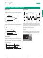
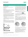
Sound pressure level
For pump types:
• Stratos PICO
• Stratos ECO
• Star-RS 25/ ..., -RS 30/ ...,
• Star-RSD 30/ ...,
• Star-Z NOVA, Star-Z 20/1, -Z 25/6
Heating, air-conditioning,
cooling
Glandless pumps are low-noise due to their design. Their air-borne
noise values with measuring-surface sound pressure level Lp (A) [dB]
depend on the motor power output, and are determined under normal operating conditions.
[dB] 60
Certificate of conformity
50
40
30
20
10
0
10
20
50
100
200
500
1000
2000
3000
Rate motor output P2
5000
[W]
Lp (A) [dB], 2-pole standard pumps (max. 2900 1/min.) and Stratos series
Lp (A) [dB], 4-pole standard pumps (max. 1450 1/min.) and TOP-E series
Available on request at additional charge for all glandless circulation
pumps of the series:
• Stratos, Stratos-D, Stratos-Z, Stratos-ZD
• TOP-S/-SD
• TOP-D
• TOP-Z
• Certificate of conformity 2.1
Content: Certification that the supplied product complies with the
order, without details of test results.
• Certificate of conformity 2.2
Content: Certification that the supplied product complies with the
order, with details of series test results.
• Acceptance test certificate 3.1
Content: Certification that the supplied product complies with the
order, with details of test results actually measured on the product.
The required test scope must be specified in advance.
Thermal insulation for heating applications
All Wilo-Stratos/Stratos-Z, Wilo-TOP-E/-S/-Z/-D and
Stratos PICO/ECO single pumps are equipped as standard with insulating shells in order to prevent heat losses from the pump housing.
Material: EPP, polypropylene foam
Thermal conductivity: 0.04 W/m K in accordance with DIN 2612
Flammability: Class B2 in accordance with DIN 4102; FMVSS 302
When insulating the pump onsite, care must be taken to cover the
pump up to the top edge of the pump housing only (the motor must
be left uncovered).
Insulation for air-conditioning/cooling applications
If pumps from the series
• Stratos, Stratos-D, Stratos-Z
• TOP-S/-SD
• TOP-D
• TOP-Z
• TOP-RL
are used in air-conditioning/cooling applications, no diffusion-proof
insulation is permitted to cover the drain labyrinth between the pump
housing and the motor. That ensures that any condensate having
possibly accumulated in the motor can drain off freely through the
condensate drain openings in the motor housing.
The Wilo-ClimaForm diffusion-proof insulation available as accessory for the Stratos, TOP-S and TOP-RL series for the insulation of
pump housings in cold water applications ensures this automatically
due to its specific design.
Wilo-ClimaForm:
• Water vapour diffusion resistance × > 7000
• Normal flammability, in accordance with DIN 4102-B2
• Part 1 Quality monitoring in accordance with DIN 18200
Quality and safety marks
Wilo Building Services catalogue – 50 Hz – Heating, air-conditioning, cooling – Edition 2011/2012 – Subject to change without prior notice
15
Planning guide
Glandless pumps (general)
Special versions
Pumps for other voltages or 60 Hz frequency possible on request (at
additional charge).
Other materials and versions (RG, PN 16) for pumps are listed in the
pump tables.
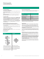
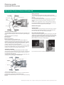
Winding
The glandless circulation pump
Rotor
With this design, all rotating components inside the canned motor
run in the pumped fluid. The required shaft seal in conventional pump
types achieved by the use of stuffing boxes or mechanical seals is
omitted. The pumped fluid lubricates the shaft bearings and cools the
components of the electric motor.
The electrical part of the pump motor (stator with winding) is separated from the encapsulated rotor compartment by means of an encapsulated motor cartridge (with the TOP Wilo series) and/or by a can
sealed off with O-rings.
Bearings
Impeller
Spacer can
Hydraulic seal
Fluid
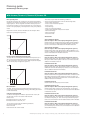
Installation positions for glandless pumps
Installation positions
not permitted
Permitted without restrictions
All energy-saving pumps,
infinitely variable control
Permitted without restrictions
All standard and secondary hot water circulation pumps,
1 or 3 speed stages
Additional terminal box positions for single and double pumps
Pump types
TOP-E 25 (30)/1-7
TOP-E 30/1-10
TOP-E 40/1-4
TOP-E 50/1-6
TOP-ED 32/1-7
TOP-ED 40/1-7
TOP-ED 50/1-6
•
–
•
–
–
–
–
–
•
•
•
–
•
•
•
Stratos ECO-Z
–
Star-RSD
–
–
–
–
Stratos PICO
•
•
–
•
•
Star-RS, Star-Z, Smart
Stratos ECO
–
•
–
–
•
–
–
–
–
–
–
–
–
•
•
•
•
–
–
–
–
–
–
–
–
–
–
Install pumps under stress-free conditions. Valid for all operating conditions.
Please ask Wilo.
16
Wilo Building Services catalogue – 50 Hz – Heating, air-conditioning, cooling – Edition 2011/2012 – Subject to change without prior notice
Planning guide
Connection information for Wilo-TOP and Wilo-Stratos
Connection of Wilo-TOP... and -Stratos... to Wilo switchgear provided by the customer
New pump type
Switchgear connection
possible according to wiring diagram
Wilo-TOP-S
Wilo-TOP-Z
Wilo-TOP-RL
Available Wilo
switchgear
IP
SK 601
SK 602/622
SK 632
S2R 3D
AR/DR/CR
A
F
–
–
–
1~
3~
WSK IP SSM
SSM
B C 1) D 1)
C
H
I
–
K
L
–
–
–
–
–
S
Wilo-TOP-SD
or
2 x Wilo-TOP-S
2 x Wilo-TOP-Z
2 x Wilo-TOP-RL
IP
A
F
–
M
–
1~
3~
WSK IP SSM
SSM
B
C 1) D 1)
C
H
I
–
K
L
N
o
P
–
–
S
Wilo-TOP-D
IP
T
U
–
–
–
1~
WSK
V
W
–
–
–
IP
3~
WSK
X 1)
X1
K
–
–
Wilo- Wilo-TOP-ED
TOP-E
Stratos-D
Stratos
Stratos-ZD
Stratos-Z
or
2 x TOP-E
2 x Stratos
2 x Stratos-Z
1~
1~
Y
Y1
L
–
–
S
J
–
–
–
S
J
–
Q or R
–
Heating, air-conditioning,
cooling
Connection of Wilo-TOP... and Stratos ... to Wilo switchgear provided by the customer
Accessories:
Modules
Wilo-IF-Module
single-phase current
WiloWilo-TOP-ED
TOP-E
Stratos-D
Stratos Stratos-ZD or
Stratos-Z
2 x TOP-E
2 x Stratos
2 x Stratos-Z
1~
1~
Yes
Yes
Yes
Yes
–
Yes
Yes
Yes
Yes
–
IP: Internal protection against unacceptably high winding temperatures, WSK: Thermal winding contacts SSM: Collective fault signal
- = connection not possible,
1) Only in conjunction with contactor and/or Wilo-SK 602/622; SK602/622 can also be used as On/Off switch or contactor
Wiring diagram A
power supply 1~230 V/N/50 Hz
Wiring diagram B
power supply 1~230 V/N/50 Hz
N
L
SK 601
N
SK 601
PE
L1 N PE PE N
2
PE L1
SK 602
SK 622
PE
L1 N PE PE N
2
N
PE L1 L2 L3 N
N
1
2
WSK
PE U
L
V W N 15 10 10 11
N
L
1) Wilo-TOP-S/-Z/-SD/-RL
N
WSK
1) 3) Wilo-TOP-S/-Z/-SD
Wilo Building Services catalogue – 50 Hz – Heating, air-conditioning, cooling – Edition 2011/2012 – Subject to change without prior notice
17
Planning guide
Connection information for Wilo-TOP and Wilo-Stratos
Connection of Wilo-TOP... and -Stratos... to Wilo switchgear provided by the customer
Wiring diagram C
power supply 3~400 V/N/50 Hz
N
SK 601
Wiring diagram D
power supply 3~400 V/N/50 Hz
PE
N
L1 N PE PE N
2
SK 601
PE L1 L2 L3 N
SK 602
SK 622
PE L1 L2 L3 N
2
PE L1 L2 L3 N
N
1
2
SK 602
SK 622
PE L1 L2 L3 N
WSK
PE U
PE
L1 N PE PE N
N
1
2
WSK
V W N 15 10 10 11
PE U
L1 L2 L3
V W N 15 10 10 11
L1 L2 L3 SSM
1) 3) Wilo-TOP-S/-Z/-SD
1) 2) 3) Wilo-TOP-S/-Z/-SD
Wiring diagram E
power supply 1~230 V/N/50 Hz
Wiring diagram F
power supply 1~230 V/N/50 Hz
L
SK 601
N
PE L
PE
L1 N PE PE N
SK 602
SK 622
2
N
PE L1 L2 L3 N
N
1
2
WSK
PE U
L
N
SSM
V W N 15 10 10 11
L
N
1) Wilo-TOP-E/-ED
Wilo-Stratos/-Z/-D/-ZD
1) Wilo-TOP-S/-Z/-SD/-RL
Wiring diagram G
power supply 3~400 V/N/50 Hz
Wiring diagram H
power supply 3~400 V/N/50 Hz
PE L
SK 602
SK 622
N
PE L1 L2 L3 N
PE L1 L2 L3 N
N
1
2
SK 602
SK 622
PE L1 L2 L3 N
WSK
PE U
V W N 15 10 10 11
L
N
WSK
1) 3) Wilo-TOP-S/-Z/-SD
18
N
1
2
WSK
PE U
V W N 15 10 10 11
L1 L2 L3
1) Wilo-TOP-S/-Z/-SD
Wilo Building Services catalogue – 50 Hz – Heating, air-conditioning, cooling – Edition 2011/2012 – Subject to change without prior notice
Planning guide
Connection information for Wilo-TOP and Wilo-Stratos
Connection of Wilo-TOP... and -Stratos... to Wilo switchgear provided by the customer
Wiring diagram J
power supply 3~400 V/N/50 Hz or 1~230 V/N/50 Hz
PE L1 L2 L3 N
SK 602
SK 622
PE L1 L2 L3 N
PE L1 L2 L3 N
N
1
SK 602
SK 622
2
PE L1 L2 L3 N
N
WSK
PE U
Heating, air-conditioning,
cooling
Wiring diagram I
power supply 3~400 V/N/50 Hz
1
2
WSK
V W N 15 10 10 11
PE U
L1 L2 L3 SSM
V W N 15 10 10 11
L
N
SSM
1) 2) 3) Wilo-TOP-S/-Z/-SD
1) 2) 3) Wilo-TOP-E/-ED
Wilo-Stratos/-Z/-D/-ZD
Wiring diagram K
power supply 3~400 V/N/50 Hz
Wiring diagram L
power supply 3~400 V/N/50 Hz
PE L1 L2 L3
PE L1 L2 L3
SK 632
SK 632
PE L1 L2 L3
PE L1 L2 L3
WSK
PE U
WSK
V W N 15 10 10 11
PE U
V W N 15 10 10 11
L1 L2 L3 SSM
L1 L2 L3
1) Wilo-TOP-S/-Z/-SD
1) 2) Wilo-TOP-S/-Z/-SD
Wiring diagram M
power supply 1~230 V/N/50 Hz
Wiring diagram N
power supply 1~230 V/N/50 Hz
PE L
PE L
N
N
S2R 3D
S2R 3D
PE L1 L2 L3 N
PE L1 L2 L3 N
WSK
WSK
PE U
V W N 15 10
1
2
PE U
11
V W N 15 10
11
1
L
N
1) 3) Wilo-TOP-S/-Z/-SD/-RL
Wilo-SE/SE-TW
2
L
N
WSK
1) Wilo-TOP-S/-Z/-SD
Wilo Building Services catalogue – 50 Hz – Heating, air-conditioning, cooling – Edition 2011/2012 – Subject to change without prior notice
19
Planning guide
Connection information for Wilo-TOP and Wilo-Stratos
Connection of Wilo-TOP... and -Stratos... to Wilo switchgear provided by the customer
Wiring diagram O
power supply 3~400 V/N/50 Hz
Wiring diagram P
power supply 3~400 V/N/50 Hz
PE L1 L2 L3 N
PE L1 L2 L3 N
S2R 3D
S2R 3D
PE L1 L2 L3 N
PE L1 L2 L3 N
WSK
WSK
PE U
V W N 15 10
PE U
11
11
1
1
2
V W N 15 10
L1 L2 L3
L1 L2 L3
2
SSM
1) Wilo-TOP-S/-Z/-SD
1) 2) Wilo-TOP-S/-Z/-SD
Wiring diagram Q
power supply 3~400 V/N/50 Hz
Wiring diagram R
power supply 1~230 V/N/50 Hz
PE L1
PE L1 L2 L3 N
N
S2R 3D
S2R 3D
PE L1 L2 L3 N
PE L1 L2 L3 N
WSK
WSK
PE U
V W N 15 10
PE U
11
11
1
1
2
V W N 15 10
L1
N
SSM
L1
2
N
SSM
1) 2) Wilo-TOP-E/-ED
Wilo-Stratos/-Z/-D/-ZD
1) 2) Wilo-TOP-E/-ED
Wilo-Stratos/-Z/-D/-ZD
Wiring diagram S
power supply 3~400 V/N/50 Hz
Wiring diagram T
power supply 1~230 V/N/50 Hz
L1
PE L1 L2 L3 N
SK 601
AR/DR/CR
N
PE
L1 N PE PE N
2
PE L1 L2 L3 N
WSK
PE U
V W N 15 10
TOP-D
L1 L3 L3
1) Wilo-TOP-S/-Z/-SD
20
SSM
U1
V1
W1
W2
U2
V2
1)
Wilo Building Services catalogue – 50 Hz – Heating, air-conditioning, cooling – Edition 2011/2012 – Subject to change without prior notice
Planning guide
Connection information for Wilo-TOP and Wilo-Stratos
Connection of Wilo-TOP... and -Stratos... to Wilo switchgear provided by the customer
Wiring diagram V
power supply 1~230 V/N/50 Hz
N
SK 601
PE L1
2
N
PE L1 L2 L3 N
N
1
2
WSK
PE U
SK 602
SK 622
N
PE L1 L2 L3 N
N
U1
V1
W1
1
2
WSK
V W N 15 10 10 11
PE U
TOP-D
PE
L1 N PE PE N
PE L1
SK 602
SK 622
Heating, air-conditioning,
cooling
Wiring diagram U
power supply 1~230 V/N/50 Hz
TOP-D
V W N 15 10 10 11
U1
V1
W1
W2
U2
V2
15 10
W2
U2
V2
WSK
1)
1) 3)
Wiring diagram W
power supply 1~230 V/N/50 Hz
Wiring diagram X
power supply 3~400 V/N/50 Hz
N
SK 601
PE L1
SK 602
SK 622
2
N
PE L1 L2 L3 N
PE L1 L2 L3 N
N
1
2
WSK
PE U
V W N 15 10 10 11
SK 602
SK 622
PE L1 L2 L3 N
U1
V1
1
2
V W N 15 10 10 11
W1
15 10
W2
N
WSK
PE U
TOP-D
PE
L1 N PE PE N
U2
TOP-D
U1
V1
W1
W2
U2
V2
WSK
V2
1) 3)
1) 3)
Wiring diagram X1
power supply 3~400 V/N/50 Hz
Wiring diagram Y
power supply 3~400 V/N/50 Hz
N
SK 601
PE
L1 N PE PE N
2
PE L1 L2 L3 N
SK 602
SK 622
PE L1 L2 L3 N
PE L1 L2 L3 N
N
1
2
WSK
PE U
SK 602
SK 622
PE L1 L2 L3 N
U1
V1
1
2
WSK
PE U
TOP-D
N
V W N 15 10 10 11
V W N 15 10 10 11
W1
TOP-D
U1
V1
W1
15 10
W2
U2
V2
W2
1)
U2
V2
WSK
1) 3)
Wilo Building Services catalogue – 50 Hz – Heating, air-conditioning, cooling – Edition 2011/2012 – Subject to change without prior notice
21
Planning guide
Connection information for Wilo-TOP and Wilo-Stratos
Connection of Wilo-TOP... and -Stratos... to Wilo switchgear provided by the customer
Wiring diagram Y1
power supply 3~400 V/N/50 Hz
PE L1 L2 L3 N
SK 602
SK 622
PE L1 L2 L3 N
N
1
2
WSK
PE U
TOP-D
V W N 15 10 10 11
U1
V1
W1
W2
U2
V2
15 10
WSK
1) 3)
1) Automatic restart after a power failure
2) After an overload fault trip of the pump (TOP or Stratos),
acknowledge the fault first at the pump, then at the switchgear
3) SK 622 additionally with terminals for collective run signals and
collective fault signals.
On replacing a three-phase pump (3~400 V) with a single-phase
pump (1~230 V) ensure protective multiple earthing.
Consultation with Wilo is required when installing Wilo pumps in
conjunction with Wilo switchgears not listed or with switchgears
not supplied by Wilo. For terminal circuit diagrams for Wilo circulation pumps, see the “Service/accessories” chapter or the pump
data.
22
Wilo Building Services catalogue – 50 Hz – Heating, air-conditioning, cooling – Edition 2011/2012 – Subject to change without prior notice
Planning guide
Designation key
Glandless pumps
Name plate designation of the Wilo-Stratos series
Series/pump type
Item no./date of manufacture
Voltage/Frequency
Power consumption/current
Insulation class
Protection class IP
PN = nominal pressure of the pump
SW = software version
Tmax = maximum fluid temperature
Typ: Stratos 30/1-12
Art.-Nr.: 2030540/11w01
Type
Wilo...
1~230V 50/60Hz P1: 16-310 W I: 0,16-1,37 A
Class F
IP 44 PN 6/10 SW≥5.01 Tmax. 110° C
S/N20000100000
Stratos
Stratos-D
Stratos-Z
Made by WILO
WILO SE Nortkirchenstr.100 44263 Dortmund Germany
Stratos-ZD
Sequential numbering
Heating, air-conditioning,
cooling
Series design
Series code for the Wilo-Stratos range
Version
High-efficiency pumps,
infinitely variable speed
Single pump
Double pump
Single pump for secondary hot
water circulation systems
Double pump for secondary
hot water circulation systems
Rating plate identification Wilo-Stratos PICO/ECO, Wilo-Star
Voltage
Frequency
Power consumption
Maximum current I
Pressure stage PN
Maximum fluid temperature Tmax
Protection class
1 ~ 230 V
50 Hz
5,8-59 W
Imax 0,46 A
PN 10
TF 110
IP 44
Stratos ECO 25/1-5
Series/pump type
Art.-No. 4092510/11w01
Item no./date of manufacture
11w01
Week
Year
WILO SE
Nortkirchenstr.100
44263 Dortmund
Germany
Series design
Series abbreviation for the programmes Wilo-Star
and Wilo-Stratos PICO/ECO
Type
Version
Wilo...
High-efficiency pumps,
infinitely variable speed
Stratos ECO
Single pump
Stratos PICO
Standard pump,
3 speed stages
Star-RS
Single pump
Star-RSD
Double pump
Star-RSL
Ventilation pump
Secondary hot water circulation pumps
Stratos ECO-Z
Single pump in highStar-Z NOVA
efficiency version
Star-Z
Single pumps,
1 or 3 speed stages
Solar thermal pumps
Stratos ECO-ST
Single pump, high-efficiency
version for solar thermal systems
Star-ST
Single pumps, 3 speed stages,
for solar thermal systems
Star-RSG
Single pumps, 3 speed stages,
for geothermal energy systems
Wilo Building Services catalogue – 50 Hz – Heating, air-conditioning, cooling – Edition 2011/2012 – Subject to change without prior notice
23
Planning guide
Designation key
Glandless pumps
Name plate designation of the Wilo-TOP range
Voltage
Frequency
Insulation class
Protection class IP
PN = nominal
pressure of
the pump
Maximum fluid
temperature Tmax
P1
(W)
380
270
195
3~400/230 V
50 Hz
Class H
PN 6/10
IP 44
I (A)
400V 230W
0,78 1,35
0,48 0,84
0,35 0,61
Tmax 130 ˚C
Made by Wilo
WILO SE Nortkirchenstr. 100 44263 Dortmund Germany
Series/pump type
Typ TOP-S30/10
Art.-No. 2066133/ 11w26
S/N20000099999
Item no./
date of manufacture
11w26
Week
Year
Maximum
current
Maximum
power consumption
Sequential
numbering
Series design
Series code for the Wilo-TOP range
Type
Version
Wilo...
Energy-saving
pumps, infinitely
variable speed
TOP-E
Single pump
TOP-ED
Double pump
Standard pumps,
2 or 3 speed stages
TOP-S/-RL
Single pump
TOP-SD
Double pump
Standard pumps,
1 speed stage
Single pump
TOP-D
Circulation pumps
for secondary hot
water circulation
systems, 3 speed
stages
TOP-Z
Single pump
Name plate designation of special versions
On request, some pumps can be supplied in the following special versions at additional charge (the type of the special version is indicated
on the name plate):
• 130 Pump with short overall length
• RG Red brass version
Example
Type
Wilo...
Star-RS 25/4 RG
24
Special version
Star-RS 24/4
with red brass housing
Wilo Building Services catalogue – 50 Hz – Heating, air-conditioning, cooling – Edition 2011/2012 – Subject to change without prior notice
Planning guide
Energy efficiency class
Glandless pumps
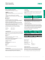
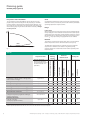
Energy efficiency class
Energy class
A
B
C
D
E
F
G
180%
Heating, air-conditioning,
cooling
160%
Relative power consumption
In the context of the Kyoto Agreement, European governments in
particular are pursuing the goal of drastically reducing CO2 emissions.
Energy labelling, particularly for high-consumption household
devices such as washing machines and refrigerators, is prescribed as
an important control element for providing the end consumer with an
aid for making decisions in favour of energy-saving appliances.
Due to the fact that heating circulation pumps are among the biggest
individual electricity consumers in household use because of their
long running times, leading European heating pump manufacturers
have voluntarily declared their intention of henceforth attaching energy labels to their heating pumps. This makes it possible for users
and end consumers to recognise, on the basis of an already familiar
classification system, whether a heating circulation pump in use is
particularly energy-efficient.
The classification of the energy efficiency of heating pumps is carried
out by means of a technical measuring procedure, which provides the
Energy Efficiency Index, EEI. The smaller the EEI, the less electrical
energy the pump consumes and the more favourable the energy
classification.
140%
120%
100%
80%
60%
40%
20%
0%
A
B
C
D
Energy class
E
F
G
Fig.: Comparison of the energy consumption rates of pumps with the same
hydraulic output
Energy Efficiency Index
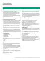
EEI < 0.4
0.4 Õ EEI < 0.6
0.6 Õ EEI < 0.8
0.8 Õ EEI < 1.0
1.0 Õ EEI < 1.2
1.2 Õ EEI < 1.4
1.4 Õ EEI
Table: Classification of the Energy Efficiency Index in 7 different
energy categories.
Fig.: Energy label for heating circulation pumps,
Example: Energy class A
The following tables list the corresponding energy class for all heating pumps to be labelled, which is incorporated in the energy label on
the packaging. In accordance with the lettering system familiar from
household appliances, A is the best possible and G is the worst possible of the energy classes.
A comparison of hydraulically similar pumps with different energy
classifications reveals that there is a difference of approximately
22% in terms of energy consumption between two sequentially
numbered energy classes. Accordingly, an energy class A pump requires on average only around 33% of the electrical energy consumed by a class D pump.
Even though the energy requirements of a class A pump are very
high, high-efficiency energy class A pumps have in the meantime become available for use throughout the entire performance range from
single-family houses to large buildings.
Wilo Building Services catalogue – 50 Hz – Heating, air-conditioning, cooling – Edition 2011/2012 – Subject to change without prior notice
25
Planning guide
EEI classifications
Glandless pumps
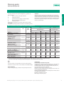
EEI classification - Single pumps/double pumps (field of application: single and two-family house)
Nominal
diameter
DN 15
(Rp ½)
DN 25
(Rp 1)
DN 30
(Rp 1 ¼)
Wilo-Stratos
PICO...
15/1-4
15/1-6
25/1-4
25/1-6
–
–
–
30/1-4
30/1-6
–
–
–
EEI
class
A
A
A
A
–
–
–
A
A
–
–
–
Wilo-Stratos
ECO...
–
–
25/1-5
–
–
–
–
30/1-5
–
–
–
–
EEI
class
WiloSmart...
EEI
class
Wilo-StarRS...
EEI
class
Wilo-StarRSD...
EEI
class
–
–
A
–
–
–
–
A
–
–
–
–
15/4
15/6
25/4
25/6
–
–
–
30/4
30/6
–
–
–
B
B
A
B
–
–
–
A
B
–
–
–
15/4
15/6
25/2
25/4
25/6
25/7
25/8
30/2
30/4
30/6
30/7
30/8
B
C
C
B
C
D
D
C
B
C
D
D
–
–
–
–
–
–
–
30/4
30/6
–
–
–
–
–
–
–
–
–
–
D
D
–
–
–
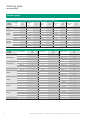
EEI classification – Single pumps (range of applications: multi-family house, commercial applications)
Nominal
diameter
DN 25 (Rp 1)
DN 30 (Rp 1 ¼)
DN 32
DN 40
DN 50
DN 65
DN 80
DN 100
26
Wilo-Stratos...
25/1-6
25/1-8
–
–
30/1-6
30/1-8
30/1-12
–
32/1-12
40/1-4
40/1-8
40/1-12
–
50/1-8
50/1-9
50/1-12
–
65/1-9
65/1-12
–
–
80/1-12
–
–
–
100/1-12
EEI
class
A
A
–
–
A
A
A
–
A
A
A
A
–
A
A
A
–
A
A
–
–
A
–
–
–
A
Wilo-TOP-E...
25/1-7
–
–
–
30/1-7
30/1-10
–
–
–
40/1-4
40/1-10
–
–
50/1-6
50/1-7
50/1-10
–
65/1-10
–
–
–
80/1-10
–
–
–
100/1-10
EEI
class
C
–
–
–
C
C
–
–
–
C
B
–
–
C
B
B
–
B
–
–
–
B
–
–
–
B
Wilo-TOP-S...
25/5 1~/3~
25/7 1~/3~
25/10 1~/3~
25/13 1~/3~
30/4 1~/3~
30/5 1~/3~
30/7 1~/3~
30/10 1~/3~
–
40/4 1~/3~
40/7 1~/3~
40/10 1~/3~
40/15 1~/3~
50/4 1~/3~
50/7 1~/3~
50/10 1~/3~
50/15
65/7 1~/3~
65/10 1~/3~
65/13
65/15
80/7 1~/3~
80/10
80/15
80/20
100/10
EEI
class
D/D
D/D
D/D
F/F
D/D
D/D
D/D
D/D
–
D/D
D/C
D/C
D/D
D/D
C/C
C/C
C
C
C
C
C
C
C
C
C
C
Wilo Building Services catalogue – 50 Hz – Heating, air-conditioning, cooling – Edition 2011/2012 – Subject to change without prior notice
Planning guide
EEI classifications
Glandless pumps
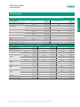
EEI classification – Single pumps (range of applications: multi-family houses, commercial applications) (continued)
DN 25 (Rp 1)
–
30 1~/3~
–
–
–
–
40 1~/3~
–
50 1~/3~
–
65 1~/3~
80 1~/3~
100 1~/3~
125
DN 30 (Rp 1 ¼)
DN 32
DN 40
DN 50
DN 65
DN 80
DN 100
DN 125
EEI
class
–
G/F
–
–
–
–
E/E
–
E/E
–
E/E
E/E
E/E
D
Wilo-TOP-RL...
25/7.5
30/4
30/6.5
30/7.5
–
–
40/4
–
–
–
–
–
–
–
EEI
class
E
D
E
E
–
–
D
–
–
–
–
–
–
–
Heating, air-conditioning,
cooling
Wilo-TOP-D...
Nominal diameter
EEI classification – double pumps (field of application: multi-family house, commercial applications)
Nominal diameter
DN 25 (Rp 1)
DN 30 (Rp 1 ¼)
DN 32
DN 40
DN 50
DN 65
DN 80
DN 100
DN 125
Wilo-Stratos-D....
–
–
32/1-8
32/1-12
40/1-8
40/1-12
–
–
50/1-8
50/1-12
–
65/1-12
–
–
80/1-12
–
–
–
–
–
EEI Class
–
–
A
A
A
A
–
–
A
A
–
A
–
–
A
–
–
–
–
–
Wilo-TOP-ED...
–
–
32/1-7
–
40/1-7
40/1-10
–
–
50/1-6
50/1-7
50/1-10
65/1-10
–
–
80/1-10
–
–
–
–
–
EEI Class
–
–
C
–
C
B
–
–
C
B
B
B
–
–
B
–
–
–
–
–
Wilo Building Services catalogue – 50 Hz – Heating, air-conditioning, cooling – Edition 2011/2012 – Subject to change without prior notice
Wilo-TOP-SD...
–
30/5 1~/3~
32/7 1~/3~
32/10 1~/3~
40/3 1~/3~
40/7 1~/3~
40/10 1~/3~
40/15 1~/3~
50/7 1~/3~
50/10 1~/3~
50/15
65/10 1~/3~
65/13
65/15
80/7 1~
80/10
80/15
80/20
–
–
EEI Class
–
D/D
E/D
D/D
E/D
D/D
E/C
E/D
F/D
E/D
D
F/D
D
D
F
D
C
C
–
–
27
Planning guide
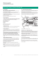
Glandless high-efficiency pumps
Wilo-Stratos / Stratos-Z / Stratos-D / Stratos-ZD
Planning guide:
Air-conditioning/cooling application
Wilo-Stratos/Stratos-Z/Stratos-D/Stratos-ZD
Wilo-Stratos is the first high-efficiency pump in glandless design
with the following advantages:
• Up to 80% electricity savings compared to standard pumps
• For all heating, air-conditioning and cooling systems in the temperature range of -10 °C to +110 °C
• Automatic adjustment of pump output to continuously varying load
conditions of the hydraulic system
• Prevention of flow noise
• Safety and comfort during installation and operation
The restriction for conventional variable speed pumps in terms of the
dependency of the fluid temperature on the ambient temperature
does not apply to the Wilo-Stratos pump.
Condensation forms on cold surfaces if the fluid temperature is lower
than the ambient temperature. The Wilo-Stratos pump can also be
used in such cases. It is designed in such a way that damage to electrical parts caused by condensation water is avoided.
Field of application
The Wilo-Stratos series is used as a high-efficiency pump in circulation systems for heating, ventilation and air-conditioning systems in
commercially-used residential and functional buildings:
• Large residential buildings
• Apartment blocks
• Residential complexes
• Hospitals
• Schools
• Administrative office buildings
• Real estate developments
Temperature range
Fluid temperature range of -10 °C to +110 °C without restriction at
an ambient temperature of -10 °C to a maximum of +40 °C.
Heating application
1 Drain labyrinth for condensation water
In nearly all circulation systems, correctly sized controlled glandless
pumps ensure adequate heat supply at all times at significantly reduced energy costs, while at the same time preventing noise generation.
Controlled heating circulation pumps have been mandated by law
under the German energy savings ordinance (EnEV)since
01.01.2002 for a nominal thermal output exceeding 25 kW.
Due to its corrosion-resistant pump housing made of red brass, the
Wilo-Stratos-Z pump is particularly suitable for installations with
possible oxygen entry such as floor heating systems made of plastic
tubing.
If the pump housing is given diffusion-proof insulation onsite, the insulation may not cover the drain labyrinth between pump housing
and motor. That ensures that any condensate having possibly accumulated in the motor can drain off freely through the condensate
drain openings in the motor housing.
The diffusion-proof Wilo-ClimaForm insulation available as accessory for the Wilo-Stratos series for the purpose of insulating pump
housings in cold water applications ensures this automatically due to
its specific design.
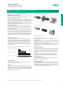
Thermal insulation for heating
Corrosion-proof pump design
The Wilo-Stratos/-Stratos-Z single pump series are equipped as
standard with a thermal insulation shell for the prevention of heat
losses through the pump housing. The PP material used, foamed
polypropylene, has the following properties:
• Environmental compatibility: easily recyclable
• Thermal resistance: up to 120 °C
• Heat transmission coefficient: 0.04 W/mK in accordance with
DIN 52612
• Flammability: Class B2 in accordance with DIN 4102 (normal flammability)
Normally flammable materials are permitted for use in heated rooms
in Germany in accordance with fire prevention regulations as long as
a minimum clearance of 20 cm is maintained between them and the
fireplace.
28
1
Insulation for air-conditioning/cooling
Corrosion-proof designs are required for e.g. cooling ceilings or ceiling heating panels. For these applications, the pump housing is coated.
As an alternative, the Wilo-Stratos-Z with its corrosion-resistant
pump housing made of red brass can be used as the highest-quality
version available.
Wilo Building Services catalogue – 50 Hz – Heating, air-conditioning, cooling – Edition 2011/2012 – Subject to change without prior notice
Planning guide
Glandless high-efficiency pumps
Wilo-Stratos / Stratos-Z / Stratos-D / Stratos-ZD
Secondary hot water circulation application
(Wilo-Stratos-Z/Stratos-ZD)
Pumps which are used in secondary hot water circulation systems are
subject to specific requirements that are fulfilled by the
Wilo-Stratos-Z/Stratos-ZD series:
• The fluids are potable water and water for food-processing companies in accordance with TrinkwV 2001 (German drinking water ordinance). Any formation of lime deposits is taken into account by the
design, meaning that a total carbonate hardness of 20°dH is permissible at a max. fluid temperature of +80 °C.
• All plastic parts that come into contact with the pumped fluid comply
with KTW recommendations.
• The differential pressure control modes Üp-c and Üp-v enable the
automatic adjustment of the pump output in volume flow-variable
secondary hot water circulation systems with thermostatically controlling line shut-off valves.
• The manual control mode enables the optimum manual adjustment
of the pump output to the constant volume flow circulation system.
This can be done with the Wilo-IR-Monitor/IR-Module for example.
The criterion for this is the temperature of the secondary hot water in
the circulation pipe, which must not be more than 5 K below the storage temperature when it enters the secondary hot water storage
tank.
High-efficiency pumps
Heating, air-conditioning,
cooling
Comparison of the motor components
Wilo-TOP-E with AC motor
Wilo-Stratos with EC motor
This has the following benefits:
The efficiency of the hydraulics and motor determine the pump's
overall efficiency. Both components were doubled with the WiloStratos pump compared to the glandless pumps previously used in
building services, thus resulting in a considerable improvement.
The applied ECM technology drastically reduces the annual power
consumption, That results in considerable savings compared to conventional pumps.
• The magnetic field required in the rotor does not need to be generated with any losses.
• Especially in the partial load range (up to 98% of the operating time),
the difference in efficiency is even greater than it already is in the full
load range compared to an asynchronous motor.
• Higher speeds are possible compared to an asynchronous motor. This
results in the reduction of the size and weight of the pump with similar hydraulics.
Annual power consumption of a heating pump (DN 30) with setback operation*
Comparison of different pump types
High-efficiency pump
Stratos 30/1-12
Energy-saving pump
TOP-E 30/1-10
Standard pump
TOP-S 30/10
396
1216
1832
0
* Load profile with 5500 operating hours per year:
1000
Power consumption [kWh/a]
2000
2% ( 110 hrs.) at 100% QN (peak load)
25% (1375 hrs.) at 65% Q N (partial load)
40% (2200 hrs.) at 30% Q N (low load)
33% (1815 hrs.) setback operation
ECM technology
The new ECM technology is the basis for the outstanding efficiency
of Wilo-Stratos pumps. It includes:
EC motor
EC stands for electronically commutated motor. Its basis is a synchronous motor with permanent magnet rotor. The rotating stator's
magnetic field is generated by electronic commutation, meaning that
the stator windings are activated specifically for the interaction of
the electrical and magnetic poles.
Wet rotor encapsulation
The rotor of the glandless pump motor runs in the fluid. This fluid lubricates the bearings and cools the motor. The current-carrying stator is separated from the fluid by a can, referred to as wet rotor encapsulation. This wet rotor encapsulation has a direct effect on the
efficiency
• due to the size of the necessary gap between stator and rotor,
• and due to the magnetic resistance of the selected can material.
The improvement in terms of efficiency of the Wilo-Stratos pump
here is the result of:
• Reduction of the air gap and
• Application of an innovative can material with smaller losses to the
magnetic flux between stator and rotor.
Hydraulic optimisation
The hydraulic conditions are optimised by means of a 3D spiral housing and 3D impeller as well as a smooth surface in the pump housing
(cataphoretic coating). The suction throat seal between impeller and
pump housing reduces radial gap losses. Axial losses are reduced by
the sealing lip on the front side of the impeller.
Wilo Building Services catalogue – 50 Hz – Heating, air-conditioning, cooling – Edition 2011/2012 – Subject to change without prior notice
29
Planning guide
Glandless high-efficiency pumps
Wilo-Stratos / Stratos-Z / Stratos-D / Stratos-ZD
Motor protection
Suction throat seal
Smooth inside
surface
3-D impeller
Lip seal
The standard integrated protection device reliably protects the
pump, in all settings, against excess temperature, excess current and
blocking.
This has the following advantage:
• No external motor protection switch is required. The connecting instructions of the local electricity supply companies are to be observed.
If, in the case of replacement, there is a motor protection switch in
the electrical installation that cannot be bridged, then it is to be set
to the maximum current specified on the name plate.
Manual control panel
3-D spiral
Operating button
The Wilo-Stratos pump is operated by means of the proven red-button technology (one-button operation). The important basic functions can be set easily and safely, directly at the pump.
Automatic performance control
The volume flow pumped through a circulation pump depends on the
thermal output/cooling output requirement of the system being supplied.
This requirement varies according to:
• Climatic changes
• User behaviour
• External heat influence
• Influence of hydraulic control devices, etc.
The circulation pump designed for maximum load conditions is
adapted to the relevant system operating status by means of a continuous comparison of the setpoint and the actual value. This automatic control adapts the pump output and thus also the power consumption continuously to actual requirements.
Electricity savings of up to 80% compared to conventional standard
pumps can be achieved by the sum of the measures described here
implemented with Wilo-Stratos high-efficiency pumps.
Non-position-dependent display
Important information during the operation of the pump is indicated
at all times by the pump display that is read at the front and is independent of its position. The extension of the manual control panel for
special applications is provided by the operating and service unit,
Wilo-IR-Monitor, via wireless communication.
Automatic ventilation
The rotor space is ventilated automatically by the filter and flow
channel system. As the fluid flows into the rotor space, a filter plug in
the shaft and a filter disc in the bearing plate reduce the ingress of
the smallest abrasive particles.
The seal between impeller and bearing plate prevents dirt from accumulating in the A-bearing gap on the motor side.
Fig.: All symbols can be read in horizontal or vertical installation
Bearing plate
Impeller
Lip seal
A-bearing
This has the following benefits:
• The automatic ventilation of the rotor space is accelerated, thus reducing both dry-running times and ventilation noise.
• Damage to the radial bearings or to the can is reduced by the filtering
feature.
30
Wilo Building Services catalogue – 50 Hz – Heating, air-conditioning, cooling – Edition 2011/2012 – Subject to change without prior notice
Planning guide
Glandless high-efficiency pumps
Control modes
Operating modes
Control mode p-c
In p-c control mode, the electronic module keeps the differential
pressure generated by the pump constant at the set differential pressure setpoint HS over the permissible volume flow range.
Automatic setback function
130
65
Power consumption
120
Feed temperature [°C]
H
Heating, air-conditioning,
cooling
Wilo-Stratos / Stratos-Z / Stratos-D / Stratos-ZD
60
100
50
80
40
60
30
40
20
H max
Hs
H min
Feed temperature
20
10
0
12:00
Q
18:00
0:00
6:00
12:00
18:00
0:00
6:00
12:00
0
18:00
Time
Fig.: Control mode p-c
Fig.: Measurement of an electronic pump with automatic setback operation
Control mode p-v
In p-v control mode, the electronic module changes the differential
pressure setpoint to be maintained by the pump in linear fashion between Hs and ½ Hs. The differential pressure setpoint value H varies
with the volume flow Q.
H
H max
Hs
The patented setback method via fuzzy control enables the further
optimisation of the output requirement of the pump under low-load
conditions of the heating system. During times when the pump performance is not required (when the heating water reaches a specific
lower temperature, e.g. due to the reduction of the feed temperature
by the weather-controlled/time-controlled heating controller), the
pump switches to a reduced constant speed.
This has the following advantage:
• This operating mode offers additional savings of up to 25 % compared to conventional heating circulation pumps with infinitely variable control.
Manual operating mode
The manual operating mode deactivates the control function in the
electronics module. The pump speed can be manually set to a constant value (for the setting range, see the pump motor data).
1
/2 Hs
H min
Q
Fig.: Control mode p-v
Control mode p-T
In control mode p-T (programmable with IR-Module, IR-Monitor,
LON or CAN), the electronic module changes the differential pressure
setpoint to be maintained by the pump according to the measured
fluid temperature. This temperature-controlled differential pressure
control mode can be used in constant-volume (e.g. single-pipe) systems and variable-delivery systems with varying feed temperature.
With the reverse effect, the p-T control mode supports the condensing boiler technology, provided the pump is installed in the return pipe of the system.
Hs
Hs
H s max
Hs var.
H s min
T min
T max
T med
Q min
Q max
Q
Fig.: Control mode p-T
Wilo Building Services catalogue – 50 Hz – Heating, air-conditioning, cooling – Edition 2011/2012 – Subject to change without prior notice
31
Planning guide
Glandless high-efficiency pumps
Wilo-Stratos / Stratos-Z / Stratos-D / Stratos-ZD
DDC operating mode
During DDC operation, the comparison of the actual value/setpoint
required for controlling is performed by an external controller. An analogue signal (0 - 10 V) is supplied to the Wilo-Stratos pump from
the external controller as a correcting variable. The current speed is
shown on the pump display, manual operation of the pump is deactivated.
Required accessories: Stratos IF-Module (see also Chapter: “WiloControl pump management systems”).
n[1/mín]
- Excess motor temperature
- Excess control module temperature
- Excess current
- Pump blockage
- Short circuit and earth leakage
- Faulty contact between motor/control module
- Mains undervoltage
- Mains overvoltage
- Electronics faults
Accessories
n máx
Stratos Modbus IF-Module
(also see Chapter: “Wilo-Control pump management systems”)
Retrofit module for retrofitting with serial, digital interface Modbus
RTU for connection to a BUS system RS485 and dual-pumps interface for communication with additional IF-Module Stratos DP.
Stratos BACnet IF-Module
(also see Chapter: “Wilo-Control pump management systems”)
Retrofit module with serial, digital interface BACnet MS/TP for connection to a BUS system RS485 and dual-pump interface for communication with additional IF-Module Stratos DP.
n mín
Off
1
2
3
10U[V]
Remote setpoint adjustment operating mode
The setpoint for controlling the internal differential pressure (p-c,
p-v) is preset for the Wilo-Stratos pump by an analogue signal,
0 - 10 V. Required accessories: Stratos IF-Module (see also Chapter:
“Wilo-Control pump management systems”).
IF-Module Stratos CAN
(also see Chapter: “Wilo-Control pump management systems”)
Retrofit module with serial, digital interface CAN for connection to a
BUS system CAN and dual-pump interface for communication with
additional IF-Module Stratos DP.
IF-Module Stratos LON
(also see Chapter: “Wilo-Control pump management systems”)
Retrofit module with serial, digital LON interface for connection to
LONWorks networks and double pump interface for communication
with an additional Stratos PLR IF-Module.
H[m]
H max
IF-Module Stratos PLR
(also see Chapter: “Wilo-Control pump management systems”)
Retrofit module with serial, digital PLR interface for connection to the
BA building automation via Wilo interface converter or onsite coupling modules and double pump interface for communication with an
additional Stratos PLR IF-Module.
H min
IF-Module Stratos DP
Retrofit module for dual-pump communication.
Aus
1
2
3
10 U[V]
BA connection
The Wilo-Stratos pumps have standard and optional interfaces for
connection to external monitoring units (e.g. BA building automation
or DDC installations).
32
The contact is open under the following conditions:
• The pump is powered and there is one of the following faults:
IF-Module Stratos Ext. Off
(also see Chapter: “Wilo-Control pump management systems”)
Retrofit module with control input “Overriding Off”, control input
0 - 10 V and dual-pump interface for communication with additional
IF-Module Stratos PLR.
Collective fault signal, SSM
A collective fault signal is available as potential-free contact, designed as NC contact in accordance with VDI 3814.
Contact load:
• Permitted minimum: 12 V DC, 10 mA,
• Permitted maximum: 250 V AC, 1 A.
IF-Module Stratos Ext. Min
(also see Chapter: “Wilo-Control pump management systems”)
Retrofit module with “Overriding Min.” control input (setback operation without Autopilot), 0 - 10 V control input and double pump interface for communication with an additional Stratos PLR IF-Module.
The contact is closed under the following conditions:
• The pump is without current
• There is no fault
• Total failure of the control module
IF-Module Stratos SBM
(also see Chapter: “Wilo-Control pump management systems”)
Retrofit module with “SBM” collective run signal, 0 - 10 V control input and double pump interface for communication with an additional
Stratos SBM IF-Module.
Wilo Building Services catalogue – 50 Hz – Heating, air-conditioning, cooling – Edition 2011/2012 – Subject to change without prior notice
Planning guide
Glandless high-efficiency pumps
Wilo-Stratos / Stratos-Z / Stratos-D / Stratos-ZD
Infrared monitoring
The Wilo-Stratos pumps are equipped with a powerful IR interface for
wireless remote control and remote diagnosis.
Heating, air-conditioning,
cooling
IF-Module Stratos Ext. Off/SBM
(also see Chapter: “Wilo-Control pump management systems”)
Retrofit module with “Overriding Off” control input, “SBM” collective
run signal and double pump interface for communication with an additional Stratos Ext. Off/SBM IF-Module.
Dual pump management
With the new high-efficiency pumps, automatic double pump control
is possible without an external control device. Required accessories:
2 Stratos IF-Modules (for optional module combinations, see catalogue section: “Wilo-Control pump management systems”).
The following operating modes are possible due to the intelligent dual pump management system with one Wilo-Stratos-D double pump
or two Wilo-Stratos single pumps:
Fig.: Wilo-IR-Module
• Standby operation
The version-specific pump output is provided by one pump, the other pump remains available on standby for time-actuated (24 hours of
pure operating time) or fault-actuated switchover.
Standby operation can be performed by all double pumps and all single pumps (2 x identical type).
• Parallel operation (in manual control mode only, n = const.)
The version-specific pump output is provided by both pumps in parallel operation. The power adjustment is achieved by the synchronous operation of both pumps. Parallel operation can be performed
by all double pumps and all single pumps (2 x identical type).
• Efficiency-optimised peak-load operation
During peak-load operation, the hydraulic output is split up between
both units of the double pump. During low-load operation (only the
base-load pump is running) the second pump is ready on standby.
The peak-load pump is also cut in during efficiency-optimised operation if load conditions require a higher pump output. Efficiency-optimised cut-in takes place when the total power consumption P1 of
both pumps is below the power consumption P1 of one pump. From
this point onwards both pumps are run up synchronously to their
maximum speed (nominal speed).
Time-dependent pump cycling (24 hours of pure operating time) assigns the basic-load function to the pumps alternately. This operating mode (load-sensitive activation/deactivation) achieves additional
energy savings compared to conventional peak-load operation.
Efficiency-optimised peak-load operation is possible with all double
pumps, as well as with two identical single pumps, if an equivalent
double pump type exists.
All basic functions of Stratos pumps can be simply adjusted directly
at the pump via the manual control panel (one-button operation).
The IR-Module is available in combination with a commercially available PDA/Pocket PC or the self-sufficient IR-Monitor as operating
and service units for IR communication. Both devices provide important additional functions that go beyond the actual pump capabilities.
The Wilo-IR-Module operating and service units (with PDA/Pocket
PC) or Wilo-IR-Monitor for:
• Inaccessibly installed pumps
• Extensive operating information
• Detailed fault diagnosis
• Statistical functions
• Special settings/control modes for special requirements
• Protection against unauthorised access
• Rotation monitoring unit for all pumps and standard motors
(only IR-Monitor)
• Storage of pump data records (only IR-Module with PDA/Pocket PC)
Like the Stratos pumps, the IR-Monitor is equipped with a one-button control and an LC display. A user program with a graphical user
interface runs on the PDA/Pocket PC.
1400
1200
Activation of peakload operation
P 1[W]
1000
800
Synchronised operation
(2 pumps)
600
Q*
400
Q* = Efficiency-optimised
cut-in and out
200
0
05
10
15
20
25
30
35
40
Q [m 3/h]
Fig.: Efficiency-optimised peak-load operation
Wilo Building Services catalogue – 50 Hz – Heating, air-conditioning, cooling – Edition 2011/2012 – Subject to change without prior notice
33
Planning guide
Glandless high-efficiency pumps
Wilo-Stratos / Stratos-Z / Stratos-D / Stratos-ZD
Application in compact distributors
Permitted installation positions
In narrow spaces, the control module can set in a vertical position by
turning the motor. Dimension b4 (see Chapter: “Dimensions,
weights”) applies as the minimum clearance (x) for the installation of
the thermal insulation shells.
Single pumps:
Double pumps:
Fig.: Simplified illustration, installation dimensions of additional valves must be
taken into account.
Installation and electrical connection
The installation of the Wilo-Stratos pump is uncomplicated, since the
flanges are well accessible due to the position of the control module
and since the terminal space is also accessible from the front. The
pump and module installation positions enable highly variable installations.
All high-efficiency pumps of the Wilo-Stratos/Stratos-Z/Stratos-D/
Stratos-ZD series can be connected to the following voltages and
frequencies:
• 1~230 V, 50/60 Hz, tolerance in accordance with
DIN IEC 60038 ± 10%
• 3~230 V, 50/60 Hz, tolerance in accordance with
DIN IEC 60038 ± 10%
34
Operation on residual-current devices (RCD)
The operation of the Wilo-Stratos series on residual-current devices
in accordance with DIN EN 61008-1 is permitted without any impairment of the operation of the residual-current device (DIN VDE 0160).
Suitable RCD circuit-breakers are indicated by or .
Wilo Building Services catalogue – 50 Hz – Heating, air-conditioning, cooling – Edition 2011/2012 – Subject to change without prior notice
Planning guide
Glandless high-efficiency pumps
Wilo-Stratos PICO / ECO-BMS / ECO-Z / ECO-Z-BMS / ECO-ST
The Wilo-Stratos PICO and Stratos ECO series with the Stratos
ECO-BMS, ECO-Z, ECO-Z-BMS and ECO-ST variants supplement the
Wilo-Stratos series mentioned above, with the following advantages:
• Up to 80% energy savings compared to standard pumps
• Stratos PICO and ECO-BMS version for all heating systems in the
temperature range +2 °C (+15 °C with ECO) to +110 °C
• Stratos ECO-ST version for solar thermal systems in the temperature
range of +15 °C to +110 °C
• Automatic adjustment of pump output to continuously varying load
conditions of the hydraulic system
• Prevention of flow noise
• Safety and comfort during installation and operation
Field of application
The Wilo-Stratos PICO, ECO-BMS and ECO-ST series are suitable for
use a high-efficiency pumps in circulation systems for heating and in
solar systems in 1-6 family houses.
Temperature range
Media temperature range from +2 °C (+15 °C with ECO) to +110 °C
with ambient temperature from 0 °C to max. +40 °C.
Heating application
The corrosion-resistant pump housing made from red brass means
that the Wilo-Stratos PICO in the RG version is particularly suitable
for systems where oxygen entry is possible, e.g. underfloor heating
with heating surfaces made from plastic tubing.
Thermal insulation for heating applications
To avoid heat losses via the pump housing, the pumps in the series
Wilo-Stratos PICO/ECO (except Stratos ECO-ST) are fitted with a
thermal insulation shell as standard. The EPP material used (foamed
polypropylene) has the following properties:
• Environmental compatibility: easily recyclable
• Thermal resistance: up to 120 °C
• Heat transmission coefficient: 0.04 W/mK in accordance with
DIN 52612
• Flammability: Class B2 in accordance with DIN 4102 (normal flammability)
Normally flammable materials are permitted for use in heated rooms
in Germany in accordance with fire prevention regulations as long as
a minimum clearance of 20 cm is maintained between them and the
fireplace.
Secondary hot water circulation application
(Wilo-Stratos ECO-Z, ECO-Z-BMS)
Pumps used in secondary hot water circulation systems are subject to
specific requirements that are fulfilled by the Wilo-Stratos ECO-Z
and ECO-Z-BMS series:
• The fluids are potable water and water for food-processing companies in accordance with TrinkwV 2001 (German drinking water ordinance) Any formation of lime deposits is taken into account by the
design, meaning that a total carbonate hardness of 20 °d is permissible at a max. fluid temperature of +65 °C.
• All plastic parts that come into contact with the pumped fluid comply
with KTW recommendations.
Automatic ventilation
The rotor space is ventilated automatically by the filter and flow
channel system. As the fluid flows into the rotor space, a filter plug in
the shaft and a filter disc in the bearing plate prevent the ingress of
the smallest abrasive particles.
The seal between impeller and bearing plate prevents dirt from accumulating in the A-bearing gap on the motor side.
This has the following benefits:
• The automatic ventilation of the rotor space is accelerated, thus reducing both dry-running times and ventilation noise.
• Damage to the radial bearings or to the can is avoided by the filtering
feature.
Heating, air-conditioning,
cooling
Wilo-Stratos PICO, Stratos ECO-BMS, Stratos ECO-Z,
Stratos ECO-Z-BMS, Stratos ECO-ST
Motor protection
The standard integrated protection device reliably protects the
pump, in all settings, against excess temperature, excess current and
blocking.
This has the following advantage:
• No external motor protection switch is required. The connecting instructions of the local electricity supply companies are to be observed.
If, in the case of replacement, there is a motor protection switch in
the electrical installation that cannot be bridged, then it is to be set
to the maximum current specified on the name plate.
Manual control panel
Operating button
All versions of the Wilo-Stratos PICO/ECO series are operated using
tried-and-tested red-button technology (one-button operation).
The important basic functions can thus be safely and comfortably set
and adjusted.
Control mode p-v
In p-v control mode, the electronic module changes the differential
pressure setpoint to be maintained by the pump in linear fashion between Hs and ½ Hs. The differential pressure setpoint value H varies
with the volume flow Q.
H
H max
Hs
1
/2 Hs
H min
Q
Fig.: Control mode p-v
Wilo Building Services catalogue – 50 Hz – Heating, air-conditioning, cooling – Edition 2011/2012 – Subject to change without prior notice
35
Planning guide
Glandless high-efficiency pumps
Wilo-Stratos PICO / ECO-BMS / ECO-Z / ECO-Z-BMS / ECO-ST
Control mode p-c
(Stratos PICO/ECO-BMS/ECO-ST additionally)
In p-c control mode, the electronic module keeps the differential
pressure generated by the pump constant at the set differential pressure setpoint HS over the permissible volume flow range.
The contact is closed under the following conditions:
• The pump is without current
• There is no fault
• Total failure of the control module
The contact is open under the following conditions:
• The pump is powered and there is one of the following faults:
H
- Excess motor temperature
- Excess control module temperature
- Excess current
- Pump blockage
- Short circuit and earth leakage
- Faulty contact between motor/control module
- Mains undervoltage
- Mains overvoltage
- Electronics faults
H max
Hs
H min
Q
Fig.: Control mode p-c
Automatic setback function
130
65
Power consumption
Feed temperature [°C]
120
60
100
50
80
40
60
30
40
20
Control input, 0 - 10 V
During DDC operation, the comparison of the actual value/setpoint
required for controlling is performed by an external controller. An
analogue signal (0 - 10 V) is sent to the Wilo-Stratos ECO-BMS/
ECO-Z-BMS and ECO-ST as correcting variable from the external
controller. As an alternative, a fixed speed can be set locally using the
red button.
n[1/mín]
n máx
Feed temperature
20
10
0
12:00
18:00
0:00
6:00
12:00
18:00
0:00
6:00
12:00
0
18:00
Time
Fig.: Measurement of an electronic pump with automatic setback operation
The patented setback method via fuzzy control enables the further
optimisation of the output requirement of the pump under low-load
conditions of the heating system. During times when the pump performance is not required (when the heating water reaches a specific
lower temperature, e.g. due to the reduction of the feed temperature
by the weather-controlled/time-controlled heating controller), the
pump switches to a reduced constant speed.
n mín
Off
1
2
3
10U[V]
External OFF control input
Input for potential-free NC contact.
The pump operates in auto control mode when the contact is closed.
An open contact stops the pump.
This has the following advantage:
• This operating mode offers additional savings of up to 25 % compared to conventional heating circulation pumps with infinitely variable control.
BA connection
(for Stratos ECO-BMS, ECO-Z-BMS and ECO-ST)
For the connection to external monitoring units (e.g. building automation BA or DDC systems), the Wilo-Stratos ECO-BMS, ECO-Z-BMS
and ECO-ST versions are standard-equipped with a collective fault
signal, the External OFF function and the 0 - 10 V control input.
Collective fault signal, SSM
A collective fault signal is available as potential-free contact, designed as NC contact in accordance with VDI 3814.
Contact load:
• Permitted minimum: 12 V DC, 10 mA,
• Permitted maximum: 250 V AC, 1 A.
36
Wilo Building Services catalogue – 50 Hz – Heating, air-conditioning, cooling – Edition 2011/2012 – Subject to change without prior notice
Planning guide
Glanded pumps (general)
This planning guide applies to:
- electronically controlled inline pumps in the series Stratos GIGA,
IP-E, DP-E, IL-E, DL-E
- Uncontrolled in-line pumps of the series: IPL, DPL, IL, DL, IPS,
IPH-O/-W, IP-Z
Pump selection
Glanded pumps are ideally suited for use in conjunction with large
plant systems covering a wide range of applications in the field of hot
water and air-conditioning/cooling. The technically correct selection
of a pump involves a number of factors:
- The correct pump size to achieve the required duty point
- The correct pump series to fulfil the process parameters
(e.g. pressure and temperature)
- The right materials to fulfil endurance requirements.
The overview duty charts in the catalogue section Series overviews
permit a rough preliminary selection of the series to be made, which
means the suitable size can be found more quickly within the series
in question. Frequently, pumps of various series are found to be
hydraulically suitable in the border area of the duty charts. Accurate
selection of the required pump size is possible only with the aid of the
individual pump curve. These are provided in this catalogue and in
the Wilo planning software (available on CD-ROM and online at
www.wilo-select.com).
The Technical data section of the catalogue provides information on
the application limits with respect to pressure, temperature and material options. In addition, this section of the catalogue provides information on the pump equipment.
Pump curve
An ideally dimensioned pump has its duty point in the region of maximum efficiency. At the duty point, there is a balance between the
performance capacity of the pump (figure 1. curve P) and the power
consumption required to overcome the resistance of the pipe system
(figure 1. curve A1). Tolerances in accordance with ISO 9906, Appendix 1. are to be taken into account for all of the pump curves illustrated.
H
[m]
Qmin
In the case of a heating pump, this is the capacity to meet the calculated standard heating load of the building. All other duty points that
occur in practice lie on the pump curve to the left of the duty point
Qnominal. The pump thus operates within its highest efficiency range.
If the actual resistance of the pipe system is lower than that on which
the pump selection has been based, then the duty point may lie outside the pump curve (figure 1. curve A2). This may lead to an unacceptably high power consumption and hence to an overload of the
selected motor. In this case it is necessary to redetermine the duty
point and, if necessary, use a more powerful pump.
Heating, air-conditioning,
cooling
Note on range of application
The minimum volumetric flow Qmin of a standard glanded pump is
10 % of Qmax (Fig. 1).
The minimum volumetric flow Qmin of an electronically controlled
glanded pump can be calculated using the following formula:
Qmin = 10% x Qmax pump x
Actual speed
max. speed
The incremental pump curves provided for pumps and, in particular,
for power selection, are intended for use when there is reliable
knowledge of the duty point. If reliable knowledge of the duty point
is not available, our basic recommendation is to select the pump with
the maximum electrical power.
Cavitation
The selection of the right pump also includes the prevention of cavitation. This is particularly the case in open systems (e. g. cooling tower systems) and at very high temperatures and low system pressures.
The pressure drop in a flowing fluid, e.g. due to frictional resistance in
the pipe, a change in absolute velocity or the geodetic head, leads to
the local formation of vapour bubbles when the static pressure falls
to the vapour pressure of the fluid (Fig. 2).
The vapour bubbles are carried along by the flow, collapsing suddenly
if the static pressure increases again above the vapour pressure
(Fig. 3).
Negative pressure
Positive pressure
A1
Qnenn
A2
Qmax
Fig. 2
Q[m3/h]
P2
[kW]
Pmax
Q[m3/h]
Fig. 1
The point of highest efficiency is approximately in the upper third of
the pump curve, or is indicated on the performance diagram. The
planning engineer must find a duty point to match the maximum requirements of the pump.
Fig. 3
This process is called cavitation. The collapse of the vapour bubbles
causes micro-jets which, on hitting the surface of a wall, cause destruction of the wall material.
To avoid cavitation, special attention must therefore be given to the
maintenance of the correct pressure. If the available intake pressure
(or static pressure) in the pipe system is not high enough to meet the
static head required for the pump (net positive suction head or
NPSH), appropriate measures must be taken to increase the static
head to at least achieve a balance. This can be done by:
- Increasing the static pressure (pump positioning).
- Reducing the fluid temperature (reduced vapour pressure pD)
- Selecting a pump with a lower net positive suction head (NPSH)
(as a rule a larger pump)
Wilo Building Services catalogue – 50 Hz – Heating, air-conditioning, cooling – Edition 2011/2012 – Subject to change without prior notice
37
Planning guide
Glanded pumps (general)
Net positive suction head NPSH
Series
The net positive suction head (NPSH) is pump-specific and is displayed in the performance diagram for the pump (Fig.4). The NPSH
values are based on the respective maximum impeller diameter. In order to allow for any uncertainty in the specification of the duty point,
when selecting the pump, the values should be increased by a margin
of safety of 0.5 m.
A hydraulically suitable pump must also meet the required operating
conditions. For this, it is necessary to check the maximum permissible
operating temperature and pressure first.
Design
In-line pumps
Wilo in-line pumps are single-stage, low-pressure centrifugal pumps
incorporating the in-line method of construction with suction pieces
and pressure ports of the same nominal diameter and with air-cooled
IEC standard motors. Flanges PN 16 with pressure measuring connections R 1/8. The pump housing is equipped with feet as standard.
H
[m]
Materials
The selection of materials for all parts that come in contact with the
fluid is of importance for the chemical resistance of the pump.
NPSH
The “Materials” table provides an overview of the most important
components. In addition to the resistance of glanded pumps,
particular significance is attached to the functional capability of the
mechanical seal.
Q[m3/h]
Fig. 4
Materials
Fluids
Shaft seal
Mechanical seal
Grey cast iron/ bronze or plastic 1)
Standard: AQEGG
S1: Q1Q1X4GG
S2: AQVGG
EPDM
Viton/HNBR
Housing seal
up to 140 °C
•
–
•
–
–
•
–
up to -20 °C
up to 30 °C
-20 °C to 40 °C
40 °C to 90 °C
-20 °C to 90 °C
90 °C to 120 °C
0 °C to 90 °C
•
•
•
•
•
•
•
–
–
–
–
–
–
–
•
•
•
–
–
–
–
–
–
–
o
o
o
–
–
–
–
–
–
–
o
•
•
•
–
–
–
–
–
–
–
o
o
o
o
-20 °C to 140 °C
•
–
–
–
o
–
o
up to 35 °C
–
o
–
o
–
–
o
up to 30 °C
–
o
–
o
–
–
o
(the max. permitted
operating temperatures
and operating pressures for
the series must be complied with)
Heating water (in accordance with VDI 2035)
(Conductivity <300 ×s, silicates <10 mg/l, solid
matter content <10 mg/l)
Cooling and cold water
Cooling brine, inorganic, pH > 7.5 inhibited
Water-glycol mixtures, 20-40 vol.% glycol
Water-glycol mixtures, 20-40 vol.% glycol
Water-glycol mixtures, 40-50 vol.% glycol
Water-glycol mixtures, 20-50 vol.% glycol
Water with oil in suspension
Mineral oil
(Comply with operating regulations relating to
explosion protection)
Swimming-pool water
(Chloride <250 mg/l,
install pump upstream of filter)
Fire water
Materials
Housing/
impeller
Grey cast iron/grey cast iron
Temperature limits
• = Standard, o = Special equipment
1)Plastic impellers standard in series IPL, DPL, IP-E, DP-E, some IPL and DPL have cast iron impeller
38
Wilo Building Services catalogue – 50 Hz – Heating, air-conditioning, cooling – Edition 2011/2012 – Subject to change without prior notice
Planning guide
Glanded pumps (general)
A mechanical shaft seal is fitted as standard in all Wilo glanded
pumps (Fig. 5). Mechanical seals are dynamic seals and are used to
seal rotating shafts at medium to high pressures. The dynamic sealing
area of the mechanical seal consists of two surface-ground, lowwearing faces (e.g. silicon carbide or carbon rings), which are pressed
together by axial forces. The slip ring rotates with the shaft, while the
counter ring remains stationary in the housing. The rings are pressed
together by a spring and the fluid pressure.
Mechanical seals – material identification code
The materials of a mechanical seal are identified by means of a 5-part
code. The “Technical data” tables for the glanded pumps contain the
code for each series. The code characters relate to the following seal
components:
1:
2:
3:
4:
5:
Heating, air-conditioning,
cooling
Mechanical seal
Slip ring
Counter ring
Secondary seals
Spring
Other components
Typical materials:
1:
2:
3:
Fig. 5
As a rule, there is little or no drip leakage during operation, and no
maintenance work is necessary. The average service life, under average operating and water conditions, is between 2 and 4 years. However, extreme conditions (soiling, admixtures and overheating) may
drastically reduce the service life.
Important:
Mechanical seals are wearing parts. Dry running is not permissible as
it will lead to the destruction of the sealing faces.
The mechanical seal fitted as standard by Wilo can be used for waterglycol mixtures with 20 - 40 vol.% glycol and a fluid temperature
of Õ 40 °C.
Outside the limits of these parameters, silicate precipitation may
occur, which could damage the standard seals. Special versions are
available on request for use outside these limits. When additives such
as glycol are used, or if oil-polluted water is encountered, then in addition to the suitability of the mechanical seal, it may also be necessary to check the performance of the pump (in the case of glycol admixtures exceeding 20% volume proportion).
The following formula can be applied to determine the power
requirement P2 of a pump:
P2 =
P2
ß
Q
H
à
ρ×Q×H
367 × η
Power requirement [kW]
Density [kg/dm3]
Volume flow [m3/h]
Delivery head [m]
Pump efficiency (e.g. 0.8 at 80%)
4:
5:
A
B
Q
Q
E
E3
V
X4
G
G
Carbon-graphite (antimony impregnated)
Carbon-graphite (synthetic resin impregnated)
, approved for use with foods
Silicon carbide
Silicon carbide
EPDM
EPDM, approved for use with foods
Viton
HNBR
Stainless steel
Stainless steel
The standard seal in Wilo glanded pump is AQEGG. It is used for heating water acc. to VDI 2035, cooling and cold water as well as water/
glycol mixtures with 20-40 % glycol by volume, up to 40 °C. In water/
glycol mixtures with temperatures > 40 °C up to 120 °C or 50 % glycol by volume and temperatures from -20 °C to 120 °C, the
Q1Q1X4GG variant is recommended.
Cataphoretic coating
Wilo glanded pumps are provided as standard with cataphoretic
painting (exceptions: Series IPS, IPH-O, IPH-W, IP-Z). External components which are susceptible to corrosion such as hexagon head
bolts, couplings etc., are chromated. The advantages of these coatings lie in their resistance to corrosion caused by aggressive atmospheres, such as humid air, condensation and an environment containing salt and chemicals. To prevent rust, pumps with cast
components with a cataphoretic coating and chromated components
are suitable for heating and air-conditioning/cooling applications
both indoors and outdoors (a special motor is required for outside applications). These pumps also offer the advantage of low maintenance costs and a longer service life.
Installation notes
Installation site
The standard pumps must be installed where they are protected
against the weather, in a frost and dust-free location with good ventilation and without a potentially explosive atmosphere.
Installation positions
Pipes and pumps are to be installed in a stress-free condition. The
pipes must be mounted in such a way that the pump does not bear
the weight of the pipe. A settling section must be provided before
and after the pump, in the form of a straight pipe. The length should
be at least 5 x DN of the pump flange (Fig. 6). This measure serves to
avoid flow cavitation.
Wilo Building Services catalogue – 50 Hz – Heating, air-conditioning, cooling – Edition 2011/2012 – Subject to change without prior notice
39
Planning guide
Glanded pumps (general)
r ⬇ 2,5 · (d · 2s)
s
d
r
5d min
Fig. 6
Inline pumps are designed for direct installation in horizontal and vertical pipes (Fig. 7). Installation with the motor and the terminal box
facing downwards is not permitted. If the direction of flow of the fluid is downwards, the motor must be rotated by unfastening the fastening screws. Do not damage the housing seal when doing this. The
bleed valve of the pump must always point upwards.
ments must be smaller the lower the rotation speed. In general, it is
possible to use natural cork panels at a rotation speed of 3000 rpm
and more, rubber/metal elements at a rotation speed between 1000
and 3000 rpm and coil springs at a rotation speed below 1000 rpm.
In terms of the configuration of the foundation, care should be taken
to avoid any acoustic bridges being formed by plaster, tiles or secondary structures since these will invalidate or significantly reduce
the insulating effect. In the case of pipe connection, it is necessary to
take account of the flexure of the flexible elements under the weight
of the pump and foundation. Planning engineers and installation
companies must take care to ensure that the pipe connections to the
pump are completely stress-free in their design and unable to exert
any gravitational or vibration influences on the pump housing whatsoever. The use of expansion joints represents a good idea in this regard.
Measures against propagation of water and solid-borne noise in
pipelines (Fig. 9)
Rubber bellows expansion joints have proven effective as a means of
reducing noise propagation in pipelines. To enable the expansion
joint to achieve its optimum sound-insulating effect, there must be
an adequate fixed point on the side of the pipeline to be protected,
and this must be separate from the flexibly mounted foundation. The
installation instructions of the manufacturer of the expansion joint
must be followed to the letter. When selecting the expansion joint,
pay attention to resistance against the temperature and the constituents of the fluid. If necessary, use other constructions instead, e.g.
metal bellows expansion joints.
Fig. 7
1
From a motor power of 18.5 kW onwards, pumps are only allowed to
be installed with a vertical pump shaft (Fig. 8). Vertically installed
pumps must be supported on the pump bases, preferably on a concrete foundation.
1
Fig. 8
2
Installing pumps on a base
Setting up the pump on a flexibly mounted foundation can improve
the insulation of the building against structure-borne noise. In order
to protect the pump when stationary against bearing damage due to
vibration from other units (e.g. in a system with several redundant
pumps), each pump should be set up on its own foundation. If pumps
are mounted on building floors then it is essential to recommend a
flexible mounting. Particular care must be taken with variable speed
pump. It is recommended - taking into account all constructionally
and acoustically relevant criteria - that a qualified building acoustics
specialist be given the task of configuration and design where necessary.
3
3
Fig. 9
Key:
1 = Pipeline fixed point
2 = Concrete foundation as settling mass
3 = Spring elements secured with dowels or glued on
The flexible elements shall be selected according to the lowest excitation frequency. This is usually the rotation speed. In the case of
variable speed, assume the lowest rotation speed. The lowest excitation frequency should be at least twice as much as the inherent frequency of the flexible mounting, so that an insulation level of at least
60 % is achieved. Therefore, the spring resilience of the flexible ele-
40
Wilo Building Services catalogue – 50 Hz – Heating, air-conditioning, cooling – Edition 2011/2012 – Subject to change without prior notice
Planning guide
Glanded pumps (general)
Anticipated noise levels for inline pumps
(for orientation purposes)
Motor
power
PN [kW]
DIN 4109 Sound insulation in buildings
VDI 2062 Vibration isolation
VDI 2715 Noise reduction in warm and hot water heating systems
VDI 3733 Noises from pipelines
VDI 3743 Emissions characteristics of pumps
Spacings and clearances
The pump must be installed in an easily accessible location, so that
approved slinging equipment can be used for maintenance work. The
minimum axial distance between the fan cover of the motor and a
wall of floor must be at least 200 mm plus the diameter of the fan
cover.
Heat insulation of pumps
In systems with thermal insulation, it is only permitted for the pump
housing to be insulated, not the lantern.
2
1
Key:
1 = Thermal insulation
2 = Ventilation
3 = Pressure measuring openings
3
0.09
0.12
0.18
0.25
0.37
0.55
0.75
1.1
1.5
2.2
3.0
4.0
5.5
7.5
11.0
15.0
18.5
22.0
30.0
37.0
45.0
55.0
75.0
90.0
110.0
132.0
160.0
200.0
Sound-pressure level pA (dB) 1)
Pump with three phase motor without speed control
Single
Double
operaoperation
tion
2-pole
pumps
54
–
47
50
–
–
54
57
47
50
52
54
60
63
60
63
67
70
67
70
67
70
67
70
71
74
71
74
74
77
74
77
74
77
76
79
79
82
79
82
–
–
–
–
–
–
–
–
–
–
–
–
–
–
–
–
Single
Double
operaoperation
tion
4-pole
pumps
–
–
50
53
53
56
47
50
58
61
58
61
51
54
53
56
55
58
59
62
59
62
59
62
63
66
63
66
65
68
65
68
71
74
71
74
72
75
73
76
73
76
74
77
72
–
70
–
72
–
72
–
72
–
73
–
Heating, air-conditioning,
cooling
Particular acoustic decoupling measures should be taken into consideration in installation locations that are sensitive to noise, such as
central roof areas, schools, concert halls or cinemas. Comply with the
following regulations, amongst others, regarding the permitted value
for noise levels in occupied rooms:
Single
operation
6-pole
pumps
–
–
–
–
–
–
–
–
–
–
–
–
65
68
–
–
–
–
–
–
–
–
–
–
–
–
–
–
1)Spatial mean value of sound-pressure levels within a cube shaped measuring
area at 1 m from the surface of the motor
Wilo Building Services catalogue – 50 Hz – Heating, air-conditioning, cooling – Edition 2011/2012 – Subject to change without prior notice
41
Planning guide
Glanded pumps (general)
Electrical drive
The rated outputs and operating values of electric drives specified in
this catalogue section for glanded pumps apply to a rated frequency
of 50 Hz, a rated voltage of 230/400 V up to 3 kW or 400/690 V from
4 kW, a coolant temperature (CT) of max. 40 °C and an installation
altitude up to 1000 m above sea level.
For cases outside these parameters a reduction of the rated output
must be applied or a larger motor type or a higher insulation class
must be selected.
All Wilo glanded pumps are standard-equipped with electric motors,
which meet the IEC standard in terms of output and design. A restriction only applies where, due to the design of the pump, coupling to a
standard motor is not possible. In this case, motors with an extended
shaft are used. The customary speed categories/operating speeds are
as follows:
Number of poles
2
4
6
50 Hz
2900 rpm
1450 rpm
950 rpm
60 Hz
3500 rpm
1750 rpm
1150 rpm
• Route data cables (e.g. PTC evaluation) separately from mains cables
• Use a sine-wave filter (LC) if necessary, in consultation with the manufacturer of the converter
Use of explosion-protected pumps according to
Directive 94/9/EC (ATEX100a)
Explosive areas are zones in which an explosive atmosphere
(gas/dust) can occur in sufficient measure to present a risk.
These areas are divided into zones. Decisions on the assignment of
zones lie with the operator and the respective regulation authority.
The testing of pumps (machines) and hence the approval for use in
hazardous areas is governed in the EU on the basis of the relevant explosion protection specification 94/9/EC (ATEX100a) by appropriate
authorised institutes. Approval is granted by means of a prototype
test certificate. Wilo glanded pumps in the series IL, DL, IPL (only variant –N), DPL (only variant -N), IPS and IPH can be supplied according
to the specifications for use in potentially explosive areas.
These pumps have a prototype test certificate in accordance with
Directive 94/9/EC (ATEX100a), which permits the following designations to be applied:
Motors in IE2 technology with greater energy efficiency
II 2 G c b II A T3, T4 / II 2 G c b II C T3, T4
From a motor power of 0.75 kW onwards, Wilo glanded pumps are
equipped as standard with IE2 motors with higher energy efficiency.
Below 0.75 kW motor power, Wilo offers electric motors as standard
with optimised degrees of efficiency.
CE
II
C
c
B
CE marking
Device group
Explosive atmosphere due to gases, vapours and mist
Design safety (protection due to safe design)
Ignition source monitoring with T4
T1 - T4
T1
T2
T3
T4
Temperature class with maximum surface
temperature
450 °C
300 °C
200 °C
135 °C
E/D
e
d
Motor ignition protection category
Increased safety
Pressure-proof enclosure
Standard pumps on external frequency converters
When standard pumps are used on external frequency converters, it
is necessary to take account of the following aspects with regard to
the insulation system and bearings isolated from the flow.
Insulation system:
400 V systems
The motors used by Wilo for glanded pumps are fitted as standard
with an insulation system in accordance with the IEC TS 60034-17
standard (fourth edition 2006-05). They are suitable for operation on
external frequency converters in all cases, providing the entire installation corresponds to the conditions stated in IEC TS 60034-17.
500 V/690 V systems
The motors which Wilo uses as standard for glanded pumps are not
suited to be used on external frequency converters with 500 V/690 V.
For use in 500 V or 690 V mains, motors with increased insulation
system are available as an option. This must be explicitly indicated
when ordering. The overall installation must comply with
IEC TS 60034-25 (Second edition 2007-03).
In this case, note in particular that for applications in the temperature
range T4, the pumps and mechanical shaft seals also have to be protected against dry running.
This can take the form, for example, of monitoring the differential
pressure or the nominal motor power.
Bearings with flow isolation:
Bearings with flow isolation are not required in the IPL, DPL, IL and DL
series if the aforementioned conditions for the insulation system are
met and the entire system is installed correctly. The following information must be complied with, however:
• The installation instructions from the manufacturer of the converter
must be complied with
• The rise times and peak voltages acc. to cable length as given in the
corresponding installation and operating instructions must be complied with
• Use a suitable cable with adequate cross-section (max. 5% voltage
loss)
• Connect the shielding correctly acc. to the manufacturer's recommendation
42
Wilo Building Services catalogue – 50 Hz – Heating, air-conditioning, cooling – Edition 2011/2012 – Subject to change without prior notice
Planning guide
Glanded pumps (general)
S
Motor according to European standard
Ex
Explosion protection
e
Ignition protection category “Increased safety”
II
Motor for potentially explosive areas
T3
Temperature class
and must also be approved in accordance with Directive 94/9/EC
(ATEX100a).
The approved operating conditions are listed in the following matrix:
Heating, air-conditioning,
cooling
Attention:
Attention must also be paid in each application case to the special
features relating to the dependency on temperature, pressure, fluid
and mechanical seal. The pumps may only be used for the permitted
fluids listed in the following matrix (II B). However, outside the pump,
the presence of gases according to the EX groups and temperature
classes is permitted (II C).
The motors have their own specific designations, e.g. EEX eII T3
which stands for:
Matrix of permitted operating conditions for pumps with ATEX approval
Mechanical
seal
Fluid II A
Heating water in accordance
with VDI 2035
Partially desalinated water with:
conductivity > 80 ¢s,
silicates < 10 mg/ l,
pH value > 9
Mineral oil
Heating water with:
Conductivity < 850 ¢s,
Silicates < 10 mg/l,
Solid content < 10 mg/ l
Condensate
Cooling brine, inorganic;
pH value > 7.5, inhibited
Water with oil contamination
Cooling water with antifreeze
(pH value: 7.5-10;
no galvanised components)
Water-glycol mixture
(20% - 40% glycol)
1)
Standard
Standard
Number of
motor
poles
2-pole
4-pole
2-pole
IL/DL
Maximum permissible
fluid temperature
T41)
P = 10 bar P = 16 bar
100 °C
90 °C
115 °C
110 °C
100 °C
90 °C
T3
P = 10 bar
140 °C
140 °C
140 °C
P = 16 bar
120 °C
120 °C
120 °C
IPL/DPL
Maximum permissible
fluid temperature
T41)
T3
P = 10 bar P = 10 bar
120 °C
120 °C
120 °C
120 °C
120 °C
120 °C
4-pole
115 °C
110 °C
140 °C
120 °C
120 °C
120 °C
2-pole
4-pole
2-pole
75 °C
95 °C
100 °C
50 °C
80 °C
90 °C
140 °C
140 °C
120 °C
115 °C
120 °C
120 °C
105 °C
115 °C
120 °C
120 °C
120 °C
120 °C
4-pole
115 °C
110 °C
120 °C
120 °C
120 °C
120 °C
2-pole
4-pole
100 °C
100 °C
90 °C
100 °C
100 °C
100 °C
100 °C
100 °C
100 °C
100 °C
100 °C
100 °C
Standard
20 °C
20 °C
20 °C
20 °C
20 °C
20 °C
G2 / S2
90 °C
90 °C
90 °C
90 °C
90 °C
90 °C
Standard
40 °C
40 °C
40 °C
40 °C
40 °C
40 °C
Standard
40 °C
40 °C
40 °C
40 °C
40 °C
40 °C
G2 / S2
Standard
Standard
Pumps and mechanical shaft seals must be additionally protected against dry running in the T4 temperature range.
This can be achieved by monitoring the differential pressure or the nominal power of the motor.
The use of solvents is not permitted, since they could corrode the
elastomers in the seals. In turn, this can lead to uncontrolled leakage!
Scope of delivery
Pump, including packaging, installation and operating instructions
Accessories
Electronically controlled in-line pumps:
- IF-Module: PLR or LON for the series IP-E, DP-E, IL-E, DL-E (also see
catalogue section “Wilo-Control Pump Management Systems”).
- IF-Module: Modbus, BACnet or CAN for the series IP-E, DP-E, IL-E,
DL-E from date of construction 10/2010.
- IR-Monitor for the series IP-E, DP-E, IL-E, DL-E.
- Interface converter analogue (also see catalogue section “Wilo-Control Pump Management Systems”).
- Interface converter digital (also see catalogue section “Wilo-Control
Pump Management Systems”).
- Brackets for installation on a base
- Blind flanges for double pumps
Wilo Building Services catalogue – 50 Hz – Heating, air-conditioning, cooling – Edition 2011/2012 – Subject to change without prior notice
43
Planning guide
Glanded pumps (general)
Inline pumps without speed control:
- Wilo-Control system for infinitely variable speed control for pump
operation according to requirements.
- Switchgears for the automatic control of operating and standby
pumps (also see catalogue section “Switchgears and control
devices”).
- Brackets for installation on a base
- Blind flanges for double pumps
Pump duty splitting
In the context of infinitely variable output control, the “split solution”
is available for optimisation, starting with the medium pump output
range (1–1.5 kW), i.e. instead of using a large pump, the maximum
output is split up between two smaller pump units or a double pump.
In the normal case, i.e. for more than 85% of the heating season, one
pump is adequate as the basic load unit. The second pump is available
to fulfil peak-load requirements.
Attention:
The extra costs for the pumps are more than compensated for by
power savings by the control device.
Advantages of pump duty splitting:
- Electricity savings of between 50% and 70%
- A second pump is always available on standby.
With the so-called “split solutions”, one pump is operated for basic
load requirements, while the other pumps are cut in a parallel circuit
for peak load duty.
This ensures that the design requirement is in accordance with
DIN 4701. In conjunction with controlled units, continuous adjustment to the load demand can be achieved over the entire performance range.
Attention:
The offers standard-equipped peak-load cut-in for all twin-head
pumps or multi-pump systems.
n=2
Delivery head H[%]
100
x 100
n=
%
PH
PH + PS
10
0%
p = constant
40
n=
60
%
0
Power requirement P[%]
QT 50 %
QV 100 %
100
Key:
PH
PS
QV
QT
P1V
P1T
Main pump
Peak-load pump
Full load volume flow
Partial load volume flow
Full load power consumption
Partial load power consumption
Investment costs
The total investment costs in heating systems can be reduced by
almost ¼ using “split solutions”. Particularly when use is made of
double pumps instead of single pumps, with their very high installation costs (Y-pipes, etc.)
Attention:
Due to their low outlet velocities, Wilo double pumps are particularly
suitable for parallel operation.
Operating costs
Considerable reductions in the operating costs also ensue as a result
of the large savings in current of the lower performance “split aggregates”, since these support better utilisation in the partial load range
and, in particular, in the low load range.
Standby
From an operating point of view, there are other advantages, since in
the event of a fault in the partial load range or the low-load range, a
100% standby option is available and in the peak-load range, on the
few extremely cold days, there is a so-called emergency standby
(75%).
Principle of operation
The duty pump and base-load pump are speed-controlled. With the
full stabilisation of this unit, i.e. with the nominal pump speed
reached and at the start of the peak-load requirement, the peak-load
unit is switched on at a fixed speed (nominal speed), while the power
of the controlled base-load pump is directly reduced and adjusted to
the load point. Resulting pressure fluctuations are relatively minor
and in practice have no appreciable effect. During parallel operation,
the output of the constant-speed peak-load unit and the controlled
base-load unit are added according to the volume flow, which in this
operating situation readjusts to the respective peak-load requirement.
The switch-point for cutting in the peak-load pump is determined by
means of an internal electronic assessment logic.
Attention:
Peak-load switching of Wilo-Control systems is only possible with
control modes according to the differential pressure or differential
temperature.
Further information on pump regulation is contained in the catalogue section “Switchgears and control systems”.
P1V
P1T
50
0
Q[%]
Fig.: Infinitely variable controlled peak-load operation of a double pump with
two motor impeller units of equal power.
44
Wilo Building Services catalogue – 50 Hz – Heating, air-conditioning, cooling – Edition 2011/2012 – Subject to change without prior notice