1
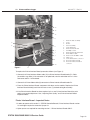
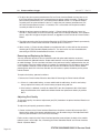
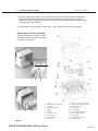
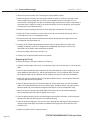
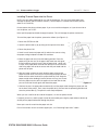
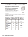
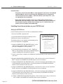
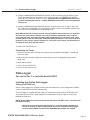
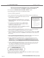
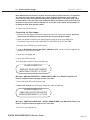
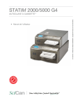
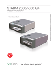
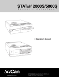
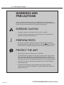
Steam
12. Printer
Generator
and Data
and Thermal
Logger Fuse
96-106775 Rev 5.0
WARNINGS AND
PRECAUTIONS
If you have questions about the unit you are repairing, please do not hesitate to
contact your local SciCan representative for information. Also, the STATIM is heavy.
Exercise caution and seek assistance when lifting or carrying units.
EXERCISE CAUTION
•
Hazardous voltages are accessible when the cover is removed.
•
Disconnect the power cord before servicing the power mains portion of the
controller board and associated devices.
PERFORM TESTS
•
If the cover is removed, a dielectric strength test (Hi-Pot) AND a protective
bonding impedance test (ground continuity) must be performed on the STATIM
when the work is completed and after the cover has been returned to the unit.
PROTECT THE UNIT
Page 240
•
Use only steam-process distilled water in the STATIM.
•
The STATIM contains electronic circuitry that is static sensitive. Always wear a
static strap when working with or near printed wiring boards. In addition, use
static footstraps, grounding mats and grounded work surfaces when servicing
microprocessor devices. Transport boards and devices in static protected bags.
•
Ensure there is sufficient steam-process distilled water in the STATIM before
activating the pump.
•
In order to ensure adherence to the applicable safety agency approvals,
state, provincial, regional and national laws, replace components with SciCan
approved parts only.
5000/5000S/5000
G4 Service
Guide
STATIM STATIM
2000/2000S
Service
Guide
12. Printer and Data Logger
96-106775 Rev 5.0
Printer and Data Logger
STATIM 5000/5000S units are capable of operating several printing or data recording devices
depending on the model.
The following is an overview of unit variants and what can and cannot be used with them:
1995 – 2007: Statim 5000/5000S units with revision 2.x/5.x or 6.x controller board
• These were available both with and without a built-in STATPRINTER mechanism located
on the left side of the front fascia.
• The internal printer mechanism is the same as the STATPRINTER mechanism usually
associated with the external 2000/2000S STATPRINTER unit.
• Units purchased WITHOUT a printer can be retro-fitted with a printer module using part
number 01-210000 “Thermal Internal Printer Kit for STATIM 5000/5000S”.
• Note that a SciCan Data Logger cannot be fitted to these units as the chassis
cannot accommodate the installation of the appropriate cable port.
2007 onwards: Statim 5000/5000S units with revision 7.x controller board
• These units are also available both with and without a built in STATPRINTER mechanism
located on the left side of the front fascia.
• Units purchased WITHOUT a printer will have a 9-pin RS232 port located on the rear of
the chassis for connecting an external (generic) printer OR a SciCan Data Logger.
• These units can also be retro-fitted with a printer module using part number 01-210000
Thermal Internal Printer Kit for STATIM 5000/5000S.
• Units WITH an internal printer DO NOT have a 9-pin RS232 port on the rear of the
chassis but DO have a cutout in the chassis to retro-fit a port using part number 01110222S “RS232 Port Kit, STATIM 5000/5000S” should you wish to convert a printer
unit to a Data Logger unit.
General notes:
For revision 2.x/5.x/6.x controller boards
• The printer cable connector on 5000 non S units is attached to the P2 connector on the
main PCB.
• The printer cable connector on 5000 S units is attached to the P2 connector on the
pressure interface PCB.
For revision 7.x controller boards
• The printer cable connector or RS232 internal port connector on ALL 5000/5000S units
is attached to the SERIAL connector on the main PCB.
For all units
• Some internal printer module assemblies were manufactured with a ferrite core
assembled to the cable. If so, ensure the ferrite core is in place when the assembly is
reinstalled. See; “Positioning the Ferrite Core”.
STATIM 2000/2000S
STATIM 5000/5000S/5000 G4 ServiceService
Guide
Guide
Page 241
12. Printer and Data Logger
96-106775 Rev 5.0
Printer
Internal Printer
Removing and Replacing the Printer Module (where fitted).
To remove the printer module assembly (1), proceed as follows (see Figure 1):
1. Remove the cover of the STATIM unit. See chapter 6.
2. Place the cover (2) on a clean work surface to avoid scratching the cabinetry surface.
3. Remove the four screws (3) securing the printer module assembly to the fascia assembly (4).
Retain the screws.
4. Remove and place the printer face down on the work bench.
To replace the printer module (1), proceed as follows (see Figure 1):
1. Install the printer module assembly in the fascia assembly (4) using the four screws (3) retained
during disassembly.
2. If the module contains a new Printer Interface Board, or a new printer module, the print quality
may require adjustment. See; “Adjusting Print Quality” and “Printer Interface Board: Important
Notes.”
3. Replace the cover of the STATIM unit. See chapter 6.
4. Plug-in the unit power cord and turn the power switch ON.
5. Test printer.
Positioning the Ferrite Core
If the printer module assembly you are servicing was manufactured with a ferrite core attached
to the cable, the core must be present during reassembly. Position the core three to four inches
from the printer module. Apply double sided adhesive tape to the core and carefully attach it to the
fiche paper shield on the back of the printer module so the cable is not unduly strained, but will
still reach either the P2 connector on the Controller Board, or the P2 connector on the Transducer
Interface Board.
Removing and Replacing the Printer Interface Board
(module removed from fascia).
To remove the Printer Interface Board (6) from the module, proceed as follows (see Figure 1):
1. If detachable, disconnect the Printer Driver ribbon cable (9) and Printer Interface ribbon cable
(10). See Printer Interface Board: Important Notes.
2. Remove the four screws (7) from the Printer Interface Board. Retain the screws.
3. Remove and retain the Printer Interface Board and the Printer Interface Board shield (8). There
may be four nylon spacers (not shown) between the board and the stand-offs. See; “Printer
Interface Board: Important Notes.”
Page 242
5000/5000S/5000
G4 Service
Guide
STATIM STATIM
2000/2000S
Service
Guide
12. Printer and Data Logger
96-106775 Rev 5.0
13
14
12
5
8
6
2
7
1
3
9
4
1.
2.
3.
4.
5.
6.
7.
8.
9.
10.
11.
12.
13.
14.
10
Figure 1
Printer module assembly
Cover
Screws
Fascia assembly
Controller Board
Printer Interface Board
#1 Phillips screws
Printer Interface Board shield
Printer ribbon cable
Printer Controller ribbon cable
Ferrite core
Controller Board P2 connector
Pressure Interface Board
Pressure Interface Board P2
connector
11
To replace the Printer Interface Board, proceed as follows (see Figure 1):
1. Connect the Printer Interface ribbon cable (10) to Printer Interface Board header P1. Cable
(assemblies may differ). If the connector is not polarized, note the orientation of Pin 1 of the
connector and Pin 1 of the board.
2. Connect the Printer ribbon cable (9) connector to Printer Interface Board header P2.
3. Place the Printer Interface Board, component side down, on the module. Replace the Printer
Interface Board shield (8) and insert the four screws (7) retained during disassembly.
4. If the Printer Interface Board has been repaired, or is a new Printer Interface Board, the print
quality may require adjustment. See; “Adjusting Print Quality” and “Printer Interface Board:
Important Notes.”
Printer Interface Board – Important Notes
1. In order to operate with version 1.1 STATIM Controller Boards, Printer Interface Boards version
2.0 and higher require the removal of jumper J2.
2. Nylon spacers are required for mounting version 1.1 Printer Interface Boards ONLY.
STATIM 2000/2000S
STATIM 5000/5000S/5000 G4 ServiceService
Guide
Guide
Page 243
12. Printer and Data Logger
96-106775 Rev 5.0
3. To adjust the print contrast potentiometer R21 on Printer Interface Board versions prior to 2.0,
the Printer Interface Board must be removed from the printer module assembly. To adjust the
print contrast potentiometer, R21, on Printer Interface Board version 2.0, the printer module
assembly must be removed from the fascia. To adjust the print contrast potentiometer, R21,
on Printer Interface Board versions 2.1 and later, R21 is accessible with the printer module
assembly installed in the fascia.
4. Setting the printer contrast too dark on version 1.1 Printer Interface Boards may cause the
STATIM L / 5000/ 5000S to reset while printing under low line-voltage conditions. If this problem
occurs, adjust R21 to lighten the print contrast, or upgrade to a later revision of Printer Interface
Board.
5. The cable connecting the Printer Interface Board to the STATIM Controller Board is permanently
soldered to the Printer Interface Board on all boards prior to version 2.2.
6. Some version 1.1 Printer Interface Boards were fabricated with a strain-relief on the connector
attaching to STATIM Controller Board position P2. The strain-relief must be removed before
connecting to STATIM Controller Board versions 2.0 and later.
Removing and Replacing the Battery
You may encounter printers that were manufactured with replaceable batteries or printers
manufactured with soldered batteries. Replaceable batteries must be properly stored and handled
to avoid discharge. The time and date functions of the printer are battery supported when the unit
is not running. If the time or date printout is incorrect, try resetting the time and date as described
in the Operator’s Manual. Power the printer and STATIM OFF and wait several minutes before
powering them back ON. If the time and date are still incorrect, replace the battery on the printer
interface board.
To replace the battery, proceed as follows:
1. Remove the Printer Interface Board as described in Removing the Printer Interface Board.
2. a. If there is a replaceable battery, remove and discard the old battery. Install a new battery.
Always replace the battery with a fresh battery of equal rating and size.
b. If the battery is soldered, carefully de-solder BAT1 from the component side of the board.
Note the orientation of the anode and cathode. Solder the replacement battery in position
BAT1.
Adjusting Print Quality
To alter print quality, the contrast adjustment pot (R21) located on the printer Interface Board must
be adjusted.
To adjust the print quality, proceed as follows:
1. Current versions of the Printer Interface Board have the printer contrast adjustment pot (R21)
located at the edge of the board, and adjustments may be made using a small adjustment tool
while the printer module is still in the fascia assembly.
Earlier versions require that the Printer Interface board be removed from the back of the module
before the pot is accessible. See, “Removing the Printer Controller Board” and “Printer Interface
Board - Important Notes.”
Page 244
5000/5000S/5000
G4 Service
Guide
STATIM STATIM
2000/2000S
Service
Guide
12. Printer and Data Logger
96-106775 Rev 5.0
2. To adjust and test print quality, turn the unit power switch ON. Open the printer module and
enable the printer by pressing the printer power button (item 18, Figure 2). Start and then
quickly stop a cycle. Doing so causes an error message to be printed. While the error message
is printing, adjust the pot (R21).
3. If further adjustment is required, repeat steps 1 and 2. Reinstall the cover. See section 6
Removing the Printer Assembly
To remove the printer assembly (1) from
the printer module assembly (2), proceed
as follows (see Figure 2):
4
20
5
2
18
3
19
Figure 2
STATIM 2000/2000S
1
1.
2.
3.
4.
5.
6.
7.
8.
9.
10.
Cover
Printer module assembly
Hinge pin
Snap mechanism
Spring
Screws
Printer housing
Printer board
Paper roll arm
Printer door
STATIM 5000/5000S/5000 G4 ServiceService
Guide
Guide
11.
12.
13.
14.
15.
16.
17.
18.
19.
20.
Paper roll arm retaining clips
Printer board mounting holes
Mounting bosses
Printer body
Locating ribs
Print head flexible cable
Printer ribbon cable
Power button
Paper advance button
Paper feed slot
Page 245
12. Printer and Data Logger
96-106775 Rev 5.0
1. Remove the printer module. See ‘Removing the Printer Module’ above.
2. Unlatch the printer assembly from the printer module assembly. The printer assembly is held
into the module by two hinge pins (3). The pin on the bottom left of the assembly sits in a
recessed slot / retaining hole. The pin on the bottom right hand of the assembly is captured by a
snap mechanism. Deflect the snap (4) away from the printer to free the hinge pin, and swing the
assembly out of the module housing.
3. Remove the printer spring (5) from the left hand hinge pin and retain for re-assembly.
4. Using a #1 Phillips screwdriver, remove three screws (6) from the printer housing (7) and set
them aside for use in re-assembling the printer.
5. Remove the housing. Note the orientation of the printer board (8) and the paper roll arm (9)
assembled on the printer door (10).
6. Carefully lift the Printer Board upwards and away from the printer door. Be careful when
handling the board. The printer is integral to the wiring board. Do not place strain on the
connections of the ribbon cable soldered to the board.
7. Remove the paper roll arm from the clips (11).
8. Carefully rest the printer board beside the assembly.
Replacing the Printer
To replace the printer, proceed as follows (see Figure 2):
1. Carefully snap the paper roll arm (9), in the position shown, back into the clips (11) on the printer
door.
2. Place the printer board (8) back into position on the printer door (10). Note the alignment of the
printer board mounting holes (12) and the mounting bosses (13) on the printer door. The black
plastic printer body (14) rests between the locating ribs (15) on the inside of the printer door.
3. Check that the print head flex cable (16) and printer ribbon cable (17) are not pinched between
the printer door and the wiring board.
4. Place the printer housing (7) on the printer door (10). Check again to be sure that the flexible
cables are not pinched between the cover and the door. The power button (18) and the paper
advance button (19) must protrude through the openings in the cover and operate freely.
5. Secure the printer housing to the printer door with the three screws (6) retained during the
disassembly procedure. Do not over tighten these screws.
6. Place the printer spring (5) on the left hand hinge pin of the printer assembly, with the long arm
positioned to align with the long slot on the module housing.
7. Place the left hand hinge pin in the recesses slot / retaining hole and align the long spring arm.
Swing the right hand hinge pin towards the module housing and push firmly onto the snap
mechanism (4).
8. Replace the printer into the snap mechanism.
Page 246
5000/5000S/5000
G4 Service
Guide
STATIM STATIM
2000/2000S
Service
Guide
12. Printer and Data Logger
96-106775 Rev 5.0
Installing Thermal Paper into the Printer
NOTE: Use only paper approved for use with the Statprinter. The use of any other paper may
damage the printer and will void the warranty. Thermal paper is available from SciCan (SciCan
order no. 01-101657S).
Do not operate the printer without paper. If you run out of thermal paper, or if you do not wish to
use the printer, turn it OFF.
Never pull the paper backwards through the printer. This will damage the printer mechanism.
To install the paper into the printer, proceed as follows (see Figure 3.1):
1. Power the STATIM unit ON.
5
2. Open the printer door (1) by pushing on the top half of the door.
2
3. Power the printer ON.
4. Unroll a small amount of paper roll (4) and trim the corners using
the paper cutting template included with each box.
5. Move the paper roll arm(4) into the loading position. Place the
paper roll (3) on the arm so the paper strip feeds from the top of
the roll and then carefully insert it into the paper feed slot(5) until
it stops. If the paper does not feed from the top, the heat sensitive
side of the paper will not be in contact with the print head and the
printer will not print.
4
3
1
4
6. With one hand, continue to gently feed the paper strip into the
paper feed slot while at the same time pressing the paper advance
6
button with the other hand until the paper feeds by itself. Keep the
paper straight when feeding it into the printer or it may jam. Do not
force the paper into the slot! If the paper will not feed into the slot,
pre-cut the end of the roll again and reload the paper.
Figure 3.1
7. Continue to press the paper advance button (6) until the paper feeds through the paper exit slot
on the front of the printer. Then, move the paper roll (3) and arm into the operating position and
close the printer door (1). The printer is now ready to operate.
When you see a red line on one side of the paper, it is time to replace the roll.
If a paper jam occurs, and the paper cannot be removed by pressing the paper advance button (6)
do not pull the paper backwards through the printer.
Never put a utensil or tool into the paper exit slot.
For full instructions on how to remove paper jams, see “Removing Paper Jams” below.
STATIM 2000/2000S
STATIM 5000/5000S/5000 G4 ServiceService
Guide
Guide
Page 247
12. Printer and Data Logger
96-106775 Rev 5.0
To replace the paper roll (3), proceed as follows (see Figure 3.2):
1. With scissors, cut the paper between the roll (3) and the paper feed
slot (5)
5
2
2. Remove the roll from the arm and discard the unused portion.
3. Press the paper advance button (6) to feed the paper that remains in
the printer out of the slot at the front of the printer.
6
4. Install the new thermal paper roll by following the instructions
described above.
Figure 3.2
Removing Paper Jams
NOTE: If paper jams in the printer and cannot be removed by pressing the paper advance button,
the printer must be disassembled. Do not pull the paper backwards through the printer. Never put
utensils or tools into the paper exit slot.
When paper is jammed in the printer, proceed as follows:
1. Turn the host unit power OFF.
2. Make sure the printer power button (18) is in the OFF position and disconnect the printer cable
(2) (Figure 1) from the STATIM printer connector port and the printer.
3. Using scissors cut the paper between the roll and the paper feed slot (20).
4. Remove the three screws (6) from the printer housing (7) and set them aside for use in
reassembling the printer. Remove the housing.
5. Note the orientation of the exposed printed wiring board and the paper roll arm assembled on
the printer door (10). Remove the paper roll arm (9) from the clips (11).
6. Gently lift the printed wiring board (8) upwards and away from the printer door (10).
Be careful when handling the board. The printer is integral to the wiring board. Do not place
strain on the connections of the ribbon cable soldered to the board. Do not remove the
connector of the flexible cable (16) from the connector header on the board.
The paper drive mechanism on the underside of the wiring board is now exposed.
7. Using a pair of tweezers or fine needle-nosed pliers, carefully remove the paper from the
mechanism.
8. When the paper is removed, proceed as described in “Replacing the Printer.”
Page 248
5000/5000S/5000
G4 Service
Guide
STATIM STATIM
2000/2000S
Service
Guide
12. Printer and Data Logger
96-106775 Rev 5.0
External Serial Printers (for use on Rev. 7.x controller boards ONLY)
When fitting an external printer to a STATIM unit it is recommended
that a ‘till roll’, ‘point of sale’ or ‘receipt’ style printer is used similar to
the example shown:
Note that these printers are NOT sold by Scican and should be
purchased in the relevant territory by the user or the dealer for fitting.
They are readily available (typically over the internet).
These printers do not normally come with a cable as standard and a
Serial Null Modem Cable DB9F – DB25M will be required.
Recommended Printers for Statims with Revision 7
Controller Boards
The following printers have been tested by SciCan and are recommended for use as an external
printer for STATIM 5000 units with Rev. 7 boards. They may be purchased from your local
computer store or from an online supplier.
STATIM 2000/2000S
STATIM 5000/5000S/5000 G4 ServiceService
Guide
Guide
Page 249
12. Printer and Data Logger
96-106775 Rev 5.0
Important notes:
• The printers referenced above MAY be superseded from time to time. The updated
equivalent MAY be able to be used with your Statim unit but it is important to
ensure that the ‘End of Line CR/LF’, ‘Serial Port Bitrate’ and ‘Printer uses º char’
are appropriate to the new printer.
• Some of the reference numbers above may contain voltage references (e.g.
SP212FD42-120). If the voltage in your region is different, then you should ensure
that you obtain a printer with the correct voltage (e.g., for a 230V territory, the
printer reference should be SP212FD42-230).
Installing the external printer on your Statim unit.
Setting the Statim unit
Locate the printer port on the rear of the unit and proceed as follows:
1. Ensure the STATIM is powered OFF
2. Press and hold the STOP button and power ON the
STATIM unit to access the USER menu.
The following menu is now available and the display on the
LCD screen should be as highlighted.
3. Using the UNWRAPPED and WRAPPED buttons, scroll
until the cursor is next to “RS232” and select it by
pressing the RUBBER & PLASTICS button.
4. You should now have the option of “N/A”, “USB/Flash
MSD” or “Serial Printer” which can be scrolled through by
using the UNWRAPPED and WRAPPED buttons.
User Mode
Time/Date Setup
Language Setup
Unit ID Setup
Last Printout
RS232
End Of Line CR/LF
Serial Port Bitrate
Printer user ° char
Save and Exit
Exit
5. Scroll to “Serial Printer” and press the RUBBER & PLASTICS button to select and return to the
user menu.
6.Using the UNWRAPPED and WRAPPED buttons, scroll until the cursor is next to “End of Line
CR/LF” and press the RUBBER & PLASTICS button to access the options.
RS232
7. Using the UNWRAPPED and WRAPPED buttons, scroll until reaching the desired CR/LF value
in the table above (or from the printer’s user manual) and press the RUBBER & PLASTICS
button to select and return to the user menu.
8. Using the UNWRAPPED and WRAPPED buttons, scroll until the cursor is next to “Serial Port
Bitrate” and press the RUBBER & PLASTICS button to access the options.
9. Using the UNWRAPPED and WRAPPED buttons, scroll until reaching the desired Bitrate value
in the table above (or from the printer’s user manual) and press the RUBBER & PLASTICS
button to select and return to the user menu.
10. Using the UNWRAPPED and WRAPPED buttons, scroll until the cursor is next to “Printer uses
º char” and press the RUBBER & PLASTICS button to access the options.
Page 250
5000/5000S/5000
G4 Service
Guide
STATIM STATIM
2000/2000S
Service
Guide
USB/Flash
12. Printer and Data Logger
96-106775 Rev 5.0
11. Using the UNWRAPPED and WRAPPED buttons, scroll until reaching the desired Hex value
in the table above (or from the printer’s user manual) and press the RUBBER & PLASTICS
button to select and return to the user menu. Important note: the UNWRAPPED button will
increase the displayed value by 1, and the WRAPPED button will increase that displayed
value by ten.
12. Using the UNWRAPPED and WRAPPED buttons, scroll until the cursor is next to “Save and
Exit” and press the RUBBER & PLASTICS button, which will now save the data, and take you
out of the user menu and back to the operating menu.
Note: When printed or electronic records are being kept for future reference, it is important
to ensure the correct data is printed, and a check should be undertaken at this stage to
ensure that the date, time and unit number (where appropriate) are set before using a data
recording device. This may have been undertaken during installation, if not, refer to the user
manual or to this service manual’s Chapter 13, “Using the service menu” for information on
resetting the time, date and unit number.
13. Power OFF the STATIM unit.
Connecting the Printer
1. Connect the printer to the STATIM unit using a Serial Null Modem Cable DB9F – DB25M and
secure the cable.
2. Connect the printer power supply to the mains power socket as appropriate to the printer
being used.
3. Power ON the printer.
4. Power ON the STATIM unit.
5. The unit is now ready for use.
Data Logger
(for use on Rev. 7.x controller boards ONLY)
Installing the SciCan Data Logger
Setting the Statim unit
SciCan’s Data Logger can record and store cycle information onto a mass storage device (MSD)
such as a USB Flash Drive or SD memory card.
The Data Logger is supplied with two cables for connection to 25 pin (early STATIM 2000 units
only) and 9 pin (all revision 7 2000 and 5000 units) data ports. The 9 pin cable is the only one
required for 5000 units.
NOTE: Statim 5000 units manufactured with internal printers will NOT have a communication
port fitted. However,
• Units that were manufactured with Revision 7.x controller boards should have a
cut-out in the chassis with a blanking plate and can be upgraded for data logger
use by installing RS232 Port Kit Statim 5000/5000S part number 01-110222S.
STATIM 2000/2000S
STATIM 5000/5000S/5000 G4 ServiceService
Guide
Guide
Page 251
12. Printer and Data Logger
96-106775 Rev 5.0
• Units that were manufactured with Revision 2.x/5.x/6.x controller boards DO NOT
have a cut-out in the chassis and CANNOT be upgraded for data logger use.
For this operation the Null Modem Serial Cable DB9F – DB25M is required
Locate the printer port on the rear of the unit and proceed as follows:
1. Ensure the STATIM is powered OFF
2. Press and hold the STOP button and power ON the STATIM unit to access the USER menu.
3. The following menu is now available and the display on the LCD
screen should be as highlighted.
4. Using the UNWRAPPED and WRAPPED buttons, scroll until the
cursor is next to “RS232” and select it by pressing the RUBBER &
PLASTICS button.
5. You should now have the option of “N/A”, “USB/Flash MSD”
or “Serial Printer” which can be scrolled through by using the
UNWRAPPED and WRAPPED buttons.
6. Scroll to “USB/Flash MSD” and press the RUBBER & PLASTICS
button to select and return to the user menu.
User Mode
Time/Date Setup
Language Setup
Unit ID Setup
Last Printout
RS232
End Of Line CR/LF
Serial Port Bitrate
Printer user ° char
Save and Exit
Exit
7. Using the UNWRAPPED and WRAPPED buttons, scroll until the cursor is next to “Serial Port
Bitrate” and press the RUBBER & PLASTICS button to access the options.
8. Using the UNWRAPPED and WRAPPED buttons, scroll (if required) to the Bitrate value of 9600
RS232
appears in the display and then press the RUBBER & PLASTICS button to select
and return to
the user menu.
9. Using the UNWRAPPED and WRAPPED buttons, scroll until the cursor is next to “Printer uses º
char” and press the RUBBER & PLASTICS button to access the options.
10. Using the UNWRAPPED and WRAPPED buttons, scroll (if required) to the Hex value of
32 [0x20] appears in the display and then press the RUBBER & PLASTICS button to select
and return to the user menu. Important note: the UNWRAPPED button will increase the
displayed value by 1, and the WRAPPED button will increase that displayed value by ten.
11. Using the UNWRAPPED and WRAPPED buttons, scroll until the cursor is next to “Save and
Exit” and press the RUBBER & PLASTICS button, which will now take you out of the user
menu and back to the operating menu and will save your changes.
12. The LCD display should now show the following:
HH:MM DD/MM/YYYY
“MSD NOT DETECTED”/”INSERT
MSD/FLASH”/”SELECT A CYCLE”
Messages “MSD NOT DETECTED”, “INSERT MSD/FLASH” and “SELECT A CYCLE” will rotate in
sequence and not all appear at the same time.
Page 252
5000/5000S/5000
G4 Service
Guide
STATIM STATIM
2000/2000S
Service
Guide
HH:MM DD/MM/YYYY
USB/Fla
12. Printer and Data Logger
96-106775 Rev 5.0
Note: When printed or electronic records are being kept for future reference, it is important
to ensure the correct data is printed, and a check should be undertaken at this stage to
ensure that the date, time and unit number (where appropriate) are set before using a data
recording device. This may have been undertaken during installation, if not, refer to the user
manual or to this service manual’s Chapter 13, “Using the service menu” for information on
resetting the time, date and unit number.
13. Power OFF the STATIM unit
Connecting the Data Logger
1. Connect the Data Logger to the power cable attached to the transformer supplied. Important
note: ensure that the plug is fully inserted in the socket on the Data Logger.
2. Attach the adaptor suitable for your regional power supply on to the main body of the
transformer. Plug in to the mains supply BUT DO NOT SWITCH ON AT THIS TIME.
3. Ensure that the STATIM unit is powered OFF.
4. Using the Null Modem Serial Cable DB9F – DB25M supplied, connect the Data Logger to the
STATIM unit and secure the cable.
5. Power the Data Logger ON.
6. Power the STATIM unit ON.
The LCD display should now show the following:
HH:MM DD/MM/YYYY
“MSD NOT DETECTED”/”INSERT
MSD/FLASH”/”SELECT
A CYCLE”
HH:MM DD/MM/YYYY
“MSD NOT DETECTED”/”INSERT
Messages
“MSD NOT DETECTED”,
“INSERT MSD/FLASH” and “SELECT A CYCLE” will
MSD/FLASH”/”SELECT
A CYCLE”
rotate in sequence and not all appear at the same time.
7. Insert USB flash drive or SD memory card.
HH:MM DD/MM/YYYY
8. After a few seconds the LCD display should now show the following:
USB/FLASH DETECTED/SAFELY
REMOVE
MSD/SELECT
A CYCLE
HH:MM
DD/MM/YYYY
USB/FLASH DETECTED/SAFELY
REMOVE MSD/SELECT A CYCLE
Messages “USB/FLASH DETECTED”, “SAFELY REMOVE MSD” and “SELECT A CYCLE” will
rotate in sequence and not all appear at the same time.
9. The unit is now ready for use.
STATIM 2000/2000S
STATIM 5000/5000S/5000 G4 ServiceService
Guide
Guide
Page 253
12. Printer and Data Logger
96-106775 Rev 5.0
Data Logger Troubleshooting
If the display reads: “MSD NOT CONNECTED <> INSERT MSD/FLASH”, proceed as follows to
ensure everything is setup correctly.
1. Check the serial cable connection.
2. Check the power connection.
3. Ensure the lower red LED is lit. It is located between the Data Logger’s serial port and power
input.
4. Check that the Mass Storage Device (MSD) is properly inserted in the appropriate slot of the
Data Logger.
5. Repeat the instructions for Installing the Data Logger on your STATIM.
If the display reads: “SAFELY REMOVE MSD <> MSD/FLASH DETECTED”, the MSD/Flash can
be safely removed without affecting the data.
If the display reads: “MSD/FLASH FULL <> REPLACE MSD”, the MSD is full and the data should
be downloaded from the MSD.
If the MSD: has missing lines of Data, refer to the STATIM screen to confirm successful
sterilization.
The Data Logger may be reset by unplugging its power supply, disconnecting the MSD and
waiting 10 seconds. Then re-connect the power adapter and insert the MSD into the Data Logger.
If the problem persists, contact the SciCan Service Center.
If MSD has: Corrupt or unreadable files and/or directories, refer to the STATIM screen to confirm
successful sterilization.
The MSD may have been unplugged while data was being written to it. The MSD should NOT be
unplugged until after “SAFELY REMOVE MSD <> MSD/FLASH DETECTED” is
displayed.
The corrupted files or directories may be lost. Reformat the MSD on your computer.
Transferring data from the USB drive or SD card
Files are stored on the MSD in txt and pdf format. These can be transferred for storage on a
computer hard drive as follows:
1. Ensure the LCD screen of the STATIM reads “SAFELY REMOVE MSD <> MSD/FLASH
DETECTED” and the STATIM is in standby. THE UNIT MUST NOT BE RUN WHEN REMOVING
THE MSD.
2. Remove MSD from the Data Logger. The STATIM LCD screen should now show the following:
HH:MM DD/MM/YYYY
“MSD NOT DETECTED”/”INSERT
MSD/FLASH”/”SELECT A CYCLE”
Page 254
5000/5000S/5000
G4 Service
Guide
STATIM STATIM
2000/2000S
Service
Guide
12. Printer and Data Logger
96-106775 Rev 5.0
3. Insert the MSD in the relevant port on the computer and wait until the computer has recognised
the new device (if transferring for the first time).
4. The contents of the MSD should now be available for viewing in the appropriate application (e.g.
Windows Explorer).
5. Locate, or create the preferred folder for storing the data.
6. Data can now be transferred by either:
a. Drag and
Drop DD/MM/YYYY
HH:MM
b. Cut and Paste
c. Copy
andNOT
PasteDETECTED”/”INSERT
(if you wish to retain the data on the MSD)
“MSD
MSD/FLASH”/”SELECT A CYCLE”
7. Safely ‘eject’ the MSD as appropriate to your computer and remove the MSD.
8. Re-insert the MSD back in to the Data Logger.
9. After a few seconds the STATIM LCD display should now show the following:
HH:MM DD/MM/YYYY
USB/FLASH DETECTED/SAFELY
REMOVE MSD/SELECT A CYCLE
10. The STATIM and Data Logger are now ready for use.
Data Logger Specifications
Connection: Serial Cable DB9F-DB25M
Baud Rate: 9600
Electrical Rating: 100V-240V, 0.6A, 50/60 Hz, multiplug
ACKNOWLEDGED MSD
USB Flash Drives:
Cruzer mini 1 GB
Memorex Travel drive 1 GB
Kingston Travel drive 512 MB
PNY Attache 1 GB
Lexar Jump Drive 1 GB
SD Memory Cards:
Kingston 512 MB
Lexar 512 MB
PNY 512 MB
Ultra 512 MB
Kingston ultimate 512 MB
Other USB Flash Drives and SD Cards may also be compatible with this Data Logger.
STATIM 2000/2000S
STATIM 5000/5000S/5000 G4 ServiceService
Guide
Guide
Page 255