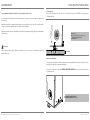
1
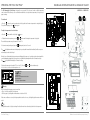
OWNER’S MANUAL | MANUEL DU PROPRIÉTAIRE | MANUAL DEL PROPIETARIO
POOL HEAT PUMP
THERMOPOMPES POUR PISCINE
BOMBA DE CALOR ELÉCTRICA PARA PISCINAS
30HPRA-E-410
50HPRA-E-410
50HPRA-E-410 (3PH)
80 HPRA-E-410
80HPRA-E-410 (3PH)
100 HPRA-E-410
100HPRA-E-410 (3PH)
43, de l’Alcazar - Blainville, Québec - Canada - J7B 1R4
www.dpopool.com
MDPL-00001A-E
B
DB
Shipping Damage MUST be reported to the Carrier IMMEDIATELY!!! Examine the exterior. Remove cover and examine
compressor and piping for signs of damage.
Warning:
Prior to starting the heat pump, you must ensure that:
> Electricity is supplied to the heat pump.
> The filter pump is operating with a minimum water circulation of 5.1 m3/h with a maximum pressure of 3 BARS.
If these two conditions are not met, the heat pump with not start. In such case, the digital display thermometer
will be unusable.
C/-&%0()0'%,/10),7'31+'%00%1%00+2'+.%20$83
//,0)%304-00$2
BCF00DF
BB<B0EF0ED
_Introduction
3
_DPL Pool Heat Pump Features
4
_Safety Precautions
5
_Operating the Pool Heat Pump
6
_General Information On Heat Pump Operation
> Beginning of season
> End of season (winterizing)
7
7
7
_Pool Heat Pump Installation
> Determining optimum location
> Clearance
> Level placement
> Securing the unit
> Condensation and drainage
> Water flow
> Electrical connections
8
8
8
8
9
9
10
10
_Electrical Specifications
11
_Connecting Electrical Conductors
12
_Wiring Diagram
13
_Plumbing Specifications
> Installation
> Check valve & chemical trap loop
> Flow rate
> External bypass
14
14
14
15
15
_Maintenance
16
_Replacement Parts Guide
17
_Pool Heat Pump Disassembly Diagram
18_19
_Troubleshooting
20_21
_Temperature Controller Programming
22
_Product Warranty
23
_Notes
24
//,0)%304-00$3
Las bombas de calor DPL están garantizadas contra cualquier defecto de fabricación (piezas y mano de obra) durante un
período de 1 año. El compresor también está garantizado durante un período de 1 año.
DPL no se responsabiliza de:
> El mantenimiento corriente;
> Los daños o reparaciones debidos a una mala instalación o uso por terceros;
> Las fallas de puesta en marcha del aparato debidas a un voltaje inadecuado, a fusibles quemados y a disyuntores de
circuito abiertos. Tampoco se hace responsable de los daños causados por insuficiencia o interrupción del servicio de
alimentación eléctrica;
> Los daños o reparaciones debidos a un uso inadecuado, abusivo, reparaciones inadecuadas, modificaciones no
autorizadas o mal funcionamiento;
> Los daños debidos a inundaciones, viento, incendios, rayos, accidentes, atmósferas corrosivas y otras condiciones que
estén fuera del control de DPL;
> Las piezas que no hayan sido suministradas o aprobadas por DPL;
> Los daños a las personas y a los bienes, sean del tipo que sean, incluyendo los daños directos, indirectos, especiales
o consecuentes, que se deban a la utilización o a la pérdida de utilización del producto.
LIMITACIÓN DE LA GARANTÍA
Esta garantía es exclusiva y sustituye a cualquier otra garantía implícita en cuanto al carácter comercial o la idoneidad
para un determinado propósito y a cualquier otra garantía expresa o implícita. Los recursos previstos en esta garantía
son exclusivos y constituyen la única obligación de DPL; cualquier otra afirmación hecha por una persona no tendrá valor
alguno.
PARA OBTENER SERVICIO
El servicio está gestionado por nuestro distribuidor autorizado. Si el servicio no lo lleva a cabo uno de nuestros representantes, la garantía podría anularse.
Si no puede resolver el problema por sí mismo, llame a su distribuidor autorizado.
C/-&%0()0'%,/10),7'31+'%00%1%00+2'+.%20$82
BBD=0EF0D0EF0FFBB
ED
Precaución: No modificar los parámetros de programación del control de temperatura sin ninguna justificación.
Para acceder al modo programación del control de temperatura, presione simultáneamente los botones
durante cinco (5) segundos. El visor
alumbrará y el código “F0~F8” aparecerá en la pantalla.
Para seleccionar una función (F0~F8), presione el botón
o
Una vez seleccionada la función, usted debe presionar el botón
con el fin de modificar el valor por defecto.
o
.
para regresar a la etapa anterior con el fin de seleccionar
Para salir del modo de programación del controlador, presione el botón
Dear Valued Customer,
Thank you for purchasing this DPL product.
.
Para modificar el valor por defecto, usted debe presionar los botones
Una vez modificado el valor por defecto, presione el botón
otras funciones (F0~F8).
, y
We hope that you will derive as much pleasure from using this product as we did in manufacturing it. In order to bring you
the best possible products, we want to know your comments about the product. You can e-mail us at [email protected]
or contact customer service at +1.450.818.4758
For easy reference, we suggest that you attach a copy of your sales slip/receipt to this page, along with the following
information which can be found on the manufacturer’s nameplate located on the side of the unit.
durante varios segundos.
Para ver la descripción de todas las funciones, refiérase al cuadro siguiente:
FUNCIÓN
DOMINIO DE AJUSTES
CODE
VALOR POR DEFECTO
Diferencial de temperatura
1~15°C (34~59°F)
F0
1°C (34°F)
Plazo temporizado
0~9 Minutos
F1
5 Minutos
Ajuste mínimo de la temperatura
del agua.
-10°C -Ajuste de temperatura
F2
16°C (61°F)
Serial number:
Ajuste máximo de la temperatura
del agua
Ajuste de temperatura -60 °C
F3
35°C (95°F)
Date of purchase:
Modo de operación
1:Refrigeración 2: Calefacción 3:Alarma
F4
2
Date of installation:
Calibración de la sonda de temperatura
-5~5°C (23~41°F)
F5
0
Ajustes °T deshelar (principio)
-10~0°C (14~32°F)
F6
-3°C (27°F)
Ajustes °T deshelar (Fin)
0~10°C (32~50°F)
F7
6°C (43°F)
Minimun temperatura trabajador
-10-5°C
F8
-5°C
Atención:
Model number:
Dealer’s Name and Address:
You will be asked this information if your unit requires servicing and/or for general inquiries.
La modificación de valores por defecto puede afectar el funcionamiento de la termobomba. Los valores por defecto no
deben en ningún caso ser modificados sin la autorización de DPL.
C/-&%0()0'%,/10),7'31+'%00%1%00+2'+.%20$81
//,0)%304-00$4
E00FB00FBF
EB=D0EF0BF<B
> Digital display thermostat.
> ROTARY or SCROLL energy-efficient compressor.
Las bombas de calor DPL están dotadas de dispositivos de protección que hacen que el aparato deje de funcionar en determinadas circunstancias:
> Aluminium/copper evaporator with one or two vertically-positioned ventilator(s). This configuration
greatly reduces noise output while improving heat exchange efficiency.
Interruptor de alta presión
> Titanium double coil, according to model. Titanium heat exchangers are very resistant
to all chemical imbalances.
El interruptor de alta presión protege el compresor en caso de presión excesiva en el sistema de refrigeración. Los casos
de alta presión se producen por lo general cuando el caudal de agua en el intercambiador de calor es demasiado bajo.
Basta con verificar si el circuito de alimentación está obstruido (caudal de agua) y/o limpiar el sistema de filtración para
corregir la situación.
> The cabinet of all our product are with vacuum plastic, and with Aluminium.
> Stainless steel screws with nylon washers and painted steel grill.
> Access holes for service gauges.
Interruptor de baja presión
> Superior quality thermostatic expansion valve, distributor and filter.
El interruptor de baja presión protege el compresor contra las puestas en marcha frecuentes que se producen cuando el
nivel del refrigerante es muy bajo o cuando la temperatura ambiente es demasiado baja. Este interruptor impide que la
bomba de calor entre en marcha cuando la presión en el sistema se sitúa por debajo de 2.5 BARS. Esta caída de
presión se debe habitualmente a una pérdida de refrigerante o a una temperatura ambiente inferior a 10 °C.
La formación de hielo en el evaporador también es un signo posible de baja presión.
> Safety approval by CE.
> Each Pool Heat Pump is factory run tested.
Specifications
Model
30HPRA-E-410
50HPRA-E-410
80HPRA-E-410
100HPRA-E-410
(3 PH)
(3 PH)
(3 PH)
50HPRA-E-410
80HPRA-E-410
100HPRA-E-410
Features
Temperature control
Digital display
Adjustable thermostat (°C and °F)
16~35 °C (60-95 °F)
Digital display
16~35 °C (60-95 °F)
Digital display
Digital display
16~35 °C (60-95 °F)
16~35 °C (60-95 °F)
Digital display
16~35 °C (60-95 °F)
Digital display
16~35 °C (60-95 °F)
Digital display
16~35 °C (60-95 °F)
Titanium
Titanium
Titanium
Titanium
itanium
Titanium
Titanium
Double coil
Double coil
Double coil
Double coil
Double coil
Double coil
Double coil
R410A
R410A
R410A
R410A
R410A
R410A
R410A
1.65
2.0
2.65
3.2
2.0
2.65
3.2
Automatic restart function after power failure
Yes
Yes
Yes
Yes
Yes
Yes
Yes
Compatible with salt chlorination systems
Yes
Yes
Yes
Yes
Yes
Yes
Yes
Automatic defrost operation
Yes
Yes
Yes
Yes
Yes
Yes
Yes
Galvanized steel cabinet
Yes
Yes
Yes
Yes
Yes
Yes
Yes
Heat exchanger
Heat exchanger special feature
Refrigerant type
Refrigerant charge
kg
Compressor type
Thermostatic expansion valve
Rotary
Rotary
Scroll
Scroll
Rotary
Scroll
Scroll
Included
Included
Included
Included
Included
Included
Included
Performance ratings
Power restored *
kw
10.5
14
21
26.5
14
21
26.5
Power consumed *
kw
2.17
2.65
4.7
6.3
2.65
4.7
6.3
COP (Power restored / Power consumed) *
4.9
5.3
4.5
4.2
5.3
4.5
4.2
Acoustic power
dB(A)
52
55
59
61
55
59
61
Water flow rate
m3/h
Minimum
5.1
5.1
8.2
8.2
5.1
8.2
8.2
Maximum
15
15
15
15
15
15
15
Interruptor por presión del agua
Los contactos del interruptor por presión del agua se cierran debido a la presión que ejerce el agua de la piscina que
circula por el intercambiador de calor. Cuando el caudal de agua es insuficiente o nulo, estos contactos se abren y ello
hace que el aparato deje de funcionar.
Acción retardada
Todos los modelos están equipados con un dispositivo de acción retardada de 5 minutos que impide la
activación repetida del mecanismo de protección de sobrecarga del compresor que se produce cuando el aparato trata
de ponerse en marcha antes de que se igualen las presiones en el sistema. Toda interrupción del funcionamiento —menos
las debidas a la interrupción de la corriente— provoca esta acción retardada.
Dimensions & Weight
Unit
Carton
Dimensions
mm
Width
1140
1255
1255
1255
1255
1255
1255
Height
890
930
1135
1135
930
1135
1135
Depth
385
415
415
415
415
415
415
77
88
128
128
88
128
128
1160
1275
1275
1275
1275
1275
1275
Weight
Kg
Net
Dimensions
mm
Width
Weight
Kg
Height
920
960
1360
1360
960
1360
1360
Depth
450
480
480
480
480
480
480
Shipping
85
95
138
138
95
138
138
All technical data subject to change without notice.
//,0)%304-00$5
C/-&%0()0'%,/10),7'31+'%00%1%00+2'+.%20$7A
EB=D0EF0BF<B
BF"0FDB
El termostato con pantalla digital no funciona:
> El disyuntor eléctrico se ha disparado. Póngalo en su posición inicial.
> El caudal de agua es insuficiente o la bomba de filtración no funciona. La bomba de calor DPL ha sido
diseñada para funcionar con una circulación de agua mínima de 5.1 m3/h. Ponga en marcha la bomba.
Cuando resulte imposible hacer funcionar el termostato con pantalla digital, comuníquese con nuestro Centro de Atención
al Cliente al número +1.450.818.4758.
This manual is a guide to the proper installation of the DPL Pool Heat Pump. Improper installation may result in unsafe
and dangerous conditions that will void the factory warranty. Prior to installation, read these instructions and any instructions that are packaged with separate pieces of equipment that make up the system. Please read these instructions thoroughly and carefully before attempting installation or operation. Failure to follow these instructions may result in improper
installation, operation, service, or maintenance, possibly resulting in fire, electrical shock, property damage, personal
injury, or death.
El termostato con pantalla digital funciona pero el compresor y el ventilador o ventiladores no funcionan:
General Precautions:
> El aparato se encuentra en el período de acción retardada de 5 minutos para que las presiones del sistema sean estables.
Durante este período de 5 minutos la luz “HEAT” parpadea.
> La temperatura se ha regulado a un nivel demasiado bajo. Suba el nivel de la temperatura.
> Se ha alcanzado la temperatura del agua que se desea y el aparato se volverá a poner en marcha automáticamente
cuando la temperatura baje por debajo del valor elegido.
> Ensure proper supervision of unit in the presence of children or persons unfamiliar with
pump operation.
> Do not hang or lay clothes or other objects on the unit.
> Keep the evaporator coil clean. Any restrictions to the air flow of the evaporator coil can seriously affect
system performance.
El termostato con pantalla digital muestra los códigos E1, E2, HHH, LLL:
> Hay un problema con el sensor de temperatura, comuníquese con su distribuidor (vendedor) autorizado.
> This device must be installed in compliance with national electrical standards.
El termostato con pantalla digital muestra el código E3:
> Do not insert foreign objects between the air flow swivelling blades as this may damage the
ventilator or cause injury.
> El sensor de descongelación automático, no funciona normalmente.
> The unit must never be placed on its side or upside down, as the compressor oil will run into
the cooling circuit and seriously damage the unit.
El termostato con pantalla digital se enciende y se apaga con intervalos irregulares:
> Probablemente hay un problema de funcionamiento en la bomba de calor y las razones pueden ser numerosas:
> Please be advised that attempting to repair this unit by yourself is done at your own risk. It is
recommended to contact the store of purchase or an authorized service centre.
> Presión del refrigerante demasiado alta
> Temperatura del agua demasiado alta
> Pérdida de refrigerante
> Avería del motor del ventilador
> Formación de hielo en el evaporador
> Temperatura ambiente demasiado baja
> Obstrucción del serpentín (evaporador)
DIAGNÓSTICO DE AVERÍAS
Cable para medir la temperatura de agua con problema
Sensor de temperatura ambiente con problema
Descongele el cable para medir la tempertatura con problema
La presión del sistema refrigerante está demasiado baja
La presión del sistema refrigerante demasiado alto
La presión del agua está demasiado baja
La temperatura ambiente está demasiado baja
Ve la temperatura más alto que 600C
Ve la temperatura más abajo que -100C
C/-&%0()0'%,/10),7'31+'%00%1%00+2'+.%20$79
Caution:
Demostración
E1
E4
E3
LP
HP
P
L0
HHH
LLL
The manufacturer disclaims all liability for any accident, during the installation or use of this product, as a result of the
unsafe installation of the heat pump. If you encounter difficulties during installation, please contact the store of purchase
or an authorized service centre.
Caution:
This device is not intended for use by persons with reduced physical, sensory or mental capacities (including children),
or lack of experience and knowledge, unless they are supervised by an adult or have been given instruction concerning
the use of the device. Children should be supervised to ensure that they do not play with the device.
//,0)%304-00$6
FB0F00FB0
EBBB0EF0EFBF0EF0B0CCB0EF0DB
80HPRA-E-410 - 100HPRA-E-410
7
The DPL Swimming Pool Heat Pump is designed for easy operation. The side panel contains a digital temperature
control readout. The Heat Pump is set to reach and then maintain the selected pool water temperature, as long as the pool
pump is running.
To start the unit:
5
> Press the
button. In normal operating mode, the display indicates the water temperature in centigrade degrees.
To stop the heat pump, press the
button again.
To adjust the temperature to the desired value:
35
turns on.
32
58
25
29
28
button again, for at least 5 seconds.
26
24
23
21
15
22
16
4
The
pilot light turns on whenever the heat pump is in operation, which means that the ventilator(s) and the compressor
are functioning in order to heat the pool.
20
27
17
> To return to normal operating mode, press the
31
18
19
> To adjust the water temperature, press the
or
buttons until the targeted temperature is displayed.
The available temperature range is between 18 °C and 35 °C.
34
button until the red pilot light
30
> Press the
14
13
12
buttons simultaneously
2
8
Sensor de
descongelamiento
Sensor de
temperatura del agua
Sensor ambiental
1
10
Protector
de fase
Relé
50 Hercios
Calentador
del Cárter
6
57
54
53
52
51
50
9
//,0)%304-00$7
47
48
Ventilador
3PH
Ventilador
380
TIP:
Setting the thermostat to its highest setting will not heat the water faster than setting it at the desired temperature.
Relé
415 Voltios
Válvula de
inversión
If these two conditions are not met, the heat pump will not start. In such a case, the digital display thermometer will be unusable.
Compressor
Warning:
Prior to starting the heat pump, you must ensure that:
> There is electricity supplied to the heat pump.
> The filter pump is operating with a minimum water circulation of 6 m3/h.
46
D
3PH
F
C
Relé
B
A:
pilot light
B:
pilot light
C: Digital display
D: Button to set temperature at desired value
E: Start/stop button
F: Temperature adjustment buttons
Transformador
E
A
Protección
de fase
Protector
de presión alta
Protector
de presión baja
Protector de
presión de agua
11
and
3
To display the temperature in farenheit (°F) or celcius (°C), Press the
for 3 seconds to select the desired temperature scale.
33
All models use a 5-minute time delay to prevent repeated tripping of the compressor's overload protection mechanism, which is
caused by attempting startup before system pressures are equalized. Any interruption will result in a 5-minute time delay.
The
pilot light will blink during this 5-minute time delay.
C/-&%0()0'%,/10),7'31+'%00%1%00+2'+.%20$78
EBBB0EF0EFBF0EF0B0CCB0EF0DB
FFB0B00FB00FB
50HPRA-E-410
Beginning of season:
7
> Make sure that the electrical breaker for the pool heat pump is in the OFF position.
19
> Ensure the water lines and the heat pump are reconnected and/or drain valves are closed.
18
5
> Clean the pool filter and make sure the water is flowing adequately through the pool return line (5.1 m3/h to 15 m3/h).
20
17
> Complete your normal preparation and/or cleaning of the pool for the start of the season.
4
> Switch ON the breaker for the electrical supply to the heat pump.
58
32
29
30
End of season (Winterizing)
27
28
31
> Then you need only start the unit and adjust the temperature to the desired value.
34
25
26
35
> Switch OFF the breaker for the electrical supply to the heat pump.
12
1
3
Transformador
10
8
11
Sensor de
descongelamiento
Sensor de
temperatura del agua
Sensor ambiental
Protección
de fase
Protector
de presión alta
Protector
de presión baja
Protector de
presión de agua
It is recommended to cover the heat pump with a protective cover that is available from your dealer.
33
13
14
15
16
21
23
22
24
> You must empty the unit of all water. Simply disconnect the WATER INLET and WATER OUTLET lines by unscrewing the
two union fittings on the front of the unit. To completely remove the water from the heat exchanger, you must remove the
drain cap (WINTERIZING DRAIN) that is located on the side of the unit. You must then let the water flow out until the unit is
completely emptied. (See the illustration below.)
3PH
Relé
Protector
de fase
Relé
B
6
50 Hercios
Calentador
del Cárter
A: WATER INLET
B: WATER OUTLET
C: CONDENSATION WATER DRAIN PIPE
D: WINTERIZING DRAIN (with plastic caps)
57
54
51
47
2
53
50
C
46
C/-&%0()0'%,/10),7'31+'%00%1%00+2'+.%20$77
52
48
9
Ventilador
Ventilador
3PH
380
Relé
415 Voltios
Válvula de
inversión
Compressor
A
D
//,0)%304-00$8
0FB00BB
<B0EF0FF
(3PH)
(3PH)
50HPRA-R410
(3PH)
80HPRA-R410
100HPRA-R410
P20001
P20001
P20001
P20001
P20016
P20003
P20016
P20016
P20004
P20004
P20004
P20004
P20004
P20002
P20017
P20017
P20002
P20017
P20017
1
P20006
P20018
P20018
P20006
P20018
P20018
Panel reverso
1
P20005
P20019
P20019
P20005
P20019
P20019
7
Rejilla
1o2
P20007
P20007
P20007
P20007
P20007
P20007
8
Pie
4o6
P20008
P20008
P20008
P20008
P20008
P20008
9
Cubierta de poder
1
P20020
P20020
P20020
P20020
P20020
P20020
10
Evaporador
1
P30045
P30046
P30046
P30045
P30046
P30046
11
Indicador de presión baja
1
P30019
P30019
P30019
P30019
P30019
P30019
12
Indicador de presión alta
1
P30018
P30018
P30018
P30018
P30018
P30018
13
Compartimiento eléctrico
1
P30020
P30020
P30020
P30020
P30020
P30020
14
Estructura de aluminio
1
P30021
P30022
P30022
P30061
P30022
P30022
15
Conector hermético de líquidos
2
P30081
P30081
P30081
P30081
P30081
P30081
16
Conducto de cable flexible
1
P30082
P30083
P30083
P30082
P30083
P30083
17
Termostato digital con opción de descongelamiento
1
P30142
P30142
P30142
P30142
P30142
P30142
18
Panel lateral (termostato digital)
1
P10118
P10118
P10118
P10118
P10118
P10118
19
Puerta (Termostato digital )
1
P10117
P10117
P10117
P10117
P10117
P10117
20
Tornillos (Termostato digital)
2
P30047
P30047
P30047
P30047
P30047
P30047
21
Compresor
1
P30031
P30032
P30033
P30062
P30063
P30064
22
Válvula de expansión termostática
1
P30036
P30037
P30037
P30036
P30037
P30037
23
Filtro – de secado flujo doble
1
P30149
P30149
P30149
P30149
P30149
P30149
24
Caja de conexión eléctrica
1
P30076
P30076
P30076
P30076
P30076
P30076
25
Conector eléctrico
1
P30050
P30050
P30050
P30050
P30050
P30050
26
Aislamiento
1
P30034
P30035
P30035
P30034
P30035
P30035
27
Sensor de temperatura de bobina
1
P30103
P30103
P30103
P30103
P30103
P30103
28
Sensor de temperatura de agua
1
P30099
P30026
P30026
P30099
P30026
P30026
29
Pipa de cobre (Sensor)
1
P30025
P30025
P30025
P30025
P30025
P30025
30
Pozo de titanio
1
P30024
P30024
P30024
P30024
P30024
P30024
31
Intercambiador de calor
1
P30008
P30008
P30008
P30008
P30008
P30008
32
Drenaje del intercambiador de calor de la bomba
1
P30012
P30012
P30012
P30012
P30012
P30012
33
Abrazadera(s) del Motor
1
P30009
P30010
P30010
P30009
P30010
P30010
34
Motor (es)
1o2
P30028
P30028
P30028
P30028
P30028
P30028
35
Ventilador(es)
1o2
P30027
P30027
P30027
P30027
P30027
P30027
36
Capacitor (Motor del Ventilador)
1o2
P30065
P30065
P30065
P30065
P30065
P30065
37
Interruptor automático
1
P30049
P30049
P30049
P30066
P30066
P30066
38
Válvula de 4 vías y Relé del calentador del cárter
2
P30061
P30061
P30061
P30061
P30061
P30061
39
Capacitor de funcionamiento
1
P30056
P30057
P30057
40
Clavija del capacitor
1
P30065
P30065
P30065
41
Transformador 208-230V / 24V
1
P30054
P30054
P30054
P30054
P30054
P30054
42
Relé del motor del ventilador
1
P30065
P30065
P30065
P30065
P30065
P30065
43
Caja eléctrica
1
P30058
P30058
P30058
P30058
P30058
P30058
44
Bloque terminal
1
P30052
P30052
P30052
P30052
P30052
P30052
45
Interruptor de presión del agua
1
P30051
P30051
P30051
P30051
P30051
P30051
46
Distribuidor
1
P30039
P30040
P30041
P30039
P30040
P30041
47
Interruptor de presión baja
1
P30043
P30043
P30043
P30043
P30043
P30043
48
Interruptor de presión alta
1
P30044
P30044
P30044
P30044
P30044
P30044
50
Bloque terminal (Principal)
1
P30075
P30075
P30075
P30067
P30067
P30067
51
Válvula de inversión
1
P30149
P30148
P30148
P30149
P30148
P30148
52
Conector Rotalock (parte #1 cobre)
1
P30131
P30131
P30131
P30131
P30131
P30131
53
Conector Rotalock (parte #2 anillo de teflón)
1
P30132
P30132
P30132
P30132
P30132
P30132
54
Conector Rotalock (parte #3 titanio)
1
P30133
P30133
P30133
P30133
P30133
P30133
55
Abrazadera de drenaje de condensación
1
P30073
P30073
P30073
P30073
P30073
P30073
56
Abrazadera de drenaje del intercambiador de calor
1
P30073
P30073
P30073
P30073
P30073
P30073
57
Abrazadera de válvula de acceso al refrigerante
1
P30078
P30078
P30078
P30078
P30078
P30078
58
Tapa de drenaje directo
1
P30023
P30023
P30023
P30023
P30023
P30023
No. de parte
Determining Optimum Location
Choose a location where the noise of the heat pump, when running, and the discharged air will not disturb the neighbours.
Install the Pool Heat Pump unit on a flat, stable surface that can support its weight and does not generate any unnecessary
noise and vibration.
Clearance
Choosing the location of your heat pump is very important. You should install it as close as possible to the filter system.
You should obey the clearance distances around the heat pump that are given in the drawing below.
Level Placement
We recommend that you install your heat pump on a solid base, for example two concrete tiles. Four (4) rubber pads (absorbent pads) are provided to lessen the transfer of vibrations. (See drawing below.)
60 cm (24 in) or more
(Top)
(Front)
30 cm (12 in) or more
30 cm (12 in) or more
(Side)
A
Descripción
Cantidad
1
Panel inferior
1
P20001
P20001
2
Panel izquierdo
1
P20003
P20016
3
Panel superior
1
P20004
4
Panel derecho
1
5
Panel frontal
6
50HPRA-R410
80HPRA-R410
100HPRA-R410
49
(Front)
(Side)
60 cm (24 in) or more
40 cm (16 in) or more
A
A: Concrete tile
59
60
//,0)%304-00$9
C/-&%0()0'%,/10),7'31+'%00%1%00+2'+.%20$76
BFF
Para un rendimiento óptimo de la bomba de calor, siga las siguientes instrucciones:
0FB00BB
Securing the unit
We recommend that you secure the unit to the concrete pad by using four (4) TAPCON screws and washers.
(See drawing below.)
Lave regularmente el filtro de la piscina contracorriente para que el caudal de circulación del agua sea constante en la
bomba de calor.
Mantenga la superficie del serpentín (evaporador) limpia y sin restos de papel, hojas u otros desechos. Los puede quitar fácilmente con un chorro de agua de baja presión sin dañar las aletas de aluminio.
Limpie cuidadosamente el aparato con un limpiador suave no abrasivo y sin blanqueador (lejía); enjuáguelo con una manguera
sin lanza de riego.
A: Concrete Pad
B: 1/4” x 1-1/2” Stainless Steel Concrete Screw
and Washer (Provided by installer)
C: 3/16” Drilled Hole
B
Advertencia:
Antes de efectuar cualquier tipo de trabajo en la bomba de calor, corte la corriente con el disyuntor del circuito de
alimentación eléctrica
C
3” minimum
A
Condensation and Drainage
The evaporator coil will produce condensation while the unit is running and drain at a steady rate, usually 11 to 19 liters,
depending on the ambient air temperature and humidity.
It is normal for condensation to drip out the CONDENSATION WATER DRAIN PIPE that is located on the side of the unit.
(See drawing below.)
A
A: CONDENSATION WATER DRAIN PIPE
B: WINTERIZING DRAIN (with plastic caps)
B
C/-&%0()0'%,/10),7'31+'%00%1%00+2'+.%20$75
//,0)%304-00$A
0FB00BB
DBBDF<DB0EF0F<B
B
Water flow
C
To minimize heating time, make sure all water valves are open completely, that the water level of the pool is at the
correct height. DPL Pool Heat Pump is designed to operate at full flow through the heat exchanger (condenser). A flow
rate of 6 m3/h to 15 m3/h should be maintained.
A: Entrada de agua
B: Salida de agua
C: Conexión removible incluida
Caution:
Either no flow or a low flow rate will cause the unit to shut down. The Pool Heat Pump will not operate without a flow of water.
A
C
Electrical connections
This includes the heat pump, swimming pool metal panels, light, heat pump, filter, chlorine generator, as well as any other
metal component or electrical equipment.
Some older swimming pools might not have an electrical connector cable. In such cases, you must drive
a 0.9 to 1.2 meters copper rod into the ground next to the equipment.
The ground connector of the DPL heat pump is located on the side of the unit.
(See drawing below.)
Warning:
Your warranty may be voided if the equipment is improperly connected.
Las conexiones de fábrica constan de un tubo macho roscado de 1 1/2” de diámetro que necesita un adaptador
hembra de 1 1/2” de diámetro. Utilice cinta de teflón y un producto obturador para tubos.
Conecte los tubos de PVC rígido (categoría 40) con los orificios de entrada y salida de la bomba de calor. Las juntas deben
pegarse con cola para PVC. Si no dispone de tubos rígidos, utilice tubos flexibles con abrazaderas de acero inoxidable.
Cuando haya terminado de instalar los tubos, ponga en marcha la bomba de la piscina y verifique si hay fugas.
Válvula de retención y bucle para productos químicos
Instale una válvula de retención y un bucle para productos químicos como se ve en la ilustración. El bucle debe ser por lo
menos 200 mm más alto que la parte superior del equipo de cloración para impedir que el cloro se dirija a la bomba de
calor cuando ésta no funcione. Instale una válvula de retención en el lado del bucle más próximo a la bomba de calor
para evitar que el cloro pueda dañar la bomba.
Caudal de agua
La bomba de calor DPL ha sido diseñada para funcionar a pleno régimen de alimentación de la bomba de la piscina. No
es necesario instalar una derivación cuando el caudal de circulación de agua se sitúa entre 5.1 m3/h y 15 m3/h.
A: Ground connector
Advertencia
Un caudal superior a 15 m3/h podría dañar el aparato y disminuir su eficacia.
Derivación externa
También es bueno prever una derivación externa entre los orificios de entrada y salida de agua que permita evitar la
bomba de calor cuando ésta sea objeto de trabajos de reparación o de mantenimiento.
//,0)%304-00$21
C/-&%0()0'%,/10),7'31+'%00%1%00+2'+.%20$74
EBBB0EF0DBCFBE
DFD0FFDDB0DED
30HPRA-E-410 - 50HPRA-E-410 - 80HPRA-E-410 - 100HPRA-E-410
You must remove the electrical connection box cover to access the electrical compartment. Wiring connections must be
made exactly as shown in the wiring diagram found under the top cover inside the Pool Heat Pump.
A disconnect switch must be installed near the outdoor unit for easy disconnection of power to the Pool Heat Pump.
C
E
D
A
B
3PH
Transformador
Relé
Relé
Ventilador
3PH
Calentador
del Cárter
CAUTION
50 Hercios
Relé
Ventilador
415 Voltios
Válvula de
inversión
380
A: Disconnect switch
B: Electrical conductor
C: Electrical connection box cover
D: Terminal block
E: Terminal block (3 PH]
Operating the unit with improper line voltages constitutes abuse and will affect unit reliability and operation. Do not install
a system where voltage or phase imbalances may occur above or below permissible limits.
Disengage main power disconnect before attempting installation
Compressor
WARNING
Protector
de fase
Protección
de fase
Protector
de presión alta
Protector
de presión baja
Protector de
presión de agua
Sensor ambiental
Sensor de
temperatura del agua
Sensor de
descongelamiento
//,0)%304-00$23
C/-&%0()0'%,/10),7'31+'%00%1%00+2'+.%20$72
C0FDDB
DBBDF<DB0F5DDB
Installation
> El aparato ha de ser instalado por una persona calificada en conformidad a las ordenanzas y códigos nationales
(NFC - 15 - 100).
The typical plumbing diagram illustrates the standard plumbing layout with a single heat pump unit. Following the diagram
from left to right, the plumbing sequence is as follows:
> Los cables de suministro de energía deben contar con una certificación YZW, y su peso no debe ser inferior al establecido por
el código de designación 60245 IEC 57.
Pool
> La alimentación de la bomba de calor debe efectuarse mediante un circuito eléctrico exclusivo.
Pool Pump
Filter
Heat Pump
Check Valve
Chemical Loop
Chlorinator
Pool
A detachable connection (union) must be utilized immediately adjacent to heater to facilitate servicing and winterizing of
the unit.
> Examine en el cuadro de abajo las características eléctricas, principalmente el voltaje, la capacidad
del dispositivo de protección máxima contra la irrupción de corriente y la dimensión de los conductores de alimentación.
> La unidad de condensación de la bomba de calor debe conectarse con una fuente de alimentación eléctrica
debidamente puesta a tierra. Procure que la conexión a tierra de esta unidad sea correcta.
> Consulte los códigos y normas eléctricas de su localidad antes de adquirir los cables.
> Utilice sólo cables de alimentación con hilos de cobre.
Características eléctricas
30HPRA-E-410
50HPRA-E-410
80HPRA-E-410
100HPRA-E-410
(3 PH)
(3 PH)
(3 PH)
50HPRA-E-410
80HPRA-E-410
100HPRA-E-410
Capacidad
A: Chlorinator
B: Chemical Loop or Optional Chlorine Generation System
C: Check Valve
D: Pool Heater
//,0)%304-00$25
E: E: 3 Manual Bypass Valve
(Recommended installation)
F: Filter
G: Pool Pump
C/-&%0()0'%,/10),7'31+'%00%1%00+2'+.%20$6A
BFBDF
To ensure optimum performance of the heat pump, follow these recommendations:
BBD=0EF0B0CCB0EF0DB
Fijación del aparato
Le aconsejamos fijar el aparato sobre una losa de hormigón mediante cuatro tornillos TAPCON y arandelas. (Véase la
ilustración de abajo)
> Backwash the pool filter on a regular basis in order to ensure proper flow rate through the pool heater.
> Keep the surfaces of the coil (evaporator) clean and free of any obstruction such as papers, leaves or other debris. The
aluminium fins can be easily and safely cleaned using a low pressure water spray.
A: Losa de hormigón
B: Arandela y tornillo para hormigón de acero
inoxidable de 1/4” x 1 _ (instalador incluido)
C: Almohadilla absorbente
D: Orificio perforado de 3/16”
> Carefully clean the unit using a soft, non-abrasive and bleach-free cleaner, and rinse using a garden hose without the nozzle.
B
Warning:
Before performing any maintenance on the heat pump you must turn off the electricity at the breaker of the
electrical supply line.
C
Mínimo de 3”
A
Condensación y drenaje
El serpentín del evaporador produce condensación cuando el aparato funciona. La condensación se drena a un ritmo
constante de 11 a 19 litros, según la temperatura ambiente y la humedad.
Es normal que el agua de la condensación salga por el CONDUCTO DE EVACUACIÓN DEL AGUA DE CONDENSACIÓN
situado en un lado del aparato. (Véase la ilustración de abajo)
A
A: CONDUCTO DE EVACUACIÓN DEL AGUA DE CONDENSACIÓN
B: DRENAJE PARA EL INVIERNO (con tubos de plástico)
B
//,0)%304-00$27
C/-&%0()0'%,/10),7'31+'%00%1%00+2'+.%20$68
0FB00EBFC"0EBB
BD=0CF0F0DBF0EF0B0CCB0EF0DB
50HPRA-E-410
Al empezar la temporada:
> Compruebe que el disyuntor eléctrico de la bomba de calor esté en posición OFF.
5
19
7
> Verifique que los conductos de agua se han vuelto a conectar a la bomba de calor y/o que las válvulas de drenaje se
han cerrado.
> Termine los preparativos habituales y/o la limpieza de la piscina al inicio de la temporada.
20
17
18
> Limpie el filtro de la piscina y compruebe que el agua circula con un caudal adecuado en el conducto de retorno a la
piscina (5.1 m3/h - 15 m3/h).
58
32
30
29
> Ponga en marcha la bomba y regule la temperatura a su gusto.
27
28
31
4
> Ponga el disyuntor del circuito eléctrico de alimentación de la bomba de calor en posición ON.
25
26
35
Al terminar la temporada (preparación para el invierno):
23
22
24
34
> Apague el disyuntor que alimenta la bomba.
33
13
14
15
16
21
> Hay que sacar toda el agua del aparato. Desconecte los conductos de ENTRADA DE AGUA y de SALIDA DE AGUA desenroscando los dos empalmes de la parte delantera del aparato. Para eliminar totalmente el agua en el intercambiador
de calor, hay que quitar el tapón de drenaje (drenaje para el invierno) situado en uno de los lados del aparato. Deje que
salga el agua hasta que el aparato esté totalmente vacío. (Véase la ilustración abajo)
Se aconseja cubrir la bomba de calor con una funda de protección que puede adquirir del distribuidor.
10
8
11
12
1
3
> A continuación, vuelva a conectar los dos tubos (ENTRADA DE AGUA Y SALIDA DE AGUA) y ponga el tapón de drenaje.
6
A: ENTRADA DE AGUA
B: SALIDA DE AGUA
C: CONDUCTO DE EVACUACIÓN DEL AGUA DE CONDENSACIÓN
D: DRENAJE PARA EL INVIERNO (con tubos de plástico)
48
52
57
47
51
54
A
53
50
46
2
3PH
9
B
D
//,0)%304-00$29
C
C/-&%0()0'%,/10),7'31+'%00%1%00+2'+.%20$66
CF
FEEB0EF0FEBE
The digital display thermometer will not provide a reading:
If you are unable to activate the digital display thermostat, contact our Service Centre at +1.450.818.4758.
Este manual debe servir de guía para instalar correctamente la bomba de calor para piscinas DPL. Si la instalación no es
correcta, podrían crearse condiciones de funcionamiento inseguras y peligrosas que anularían la garantía de fábrica.
Antes de empezar la instalación, lea estas instrucciones así como todas las instrucciones que acompañen a otros elementos del sistema empaquetados por separado. Le rogamos que lea todas estas instrucciones atentamente antes de
empezar a instalar o a utilizar la bomba de calor. Si no se siguen estas instrucciones, podría efectuarse una instalación
errónea u ocasionar un funcionamiento, reparación o mantenimiento inadecuados de la bomba de calor y provocar un
incendio, un choque eléctrico, daños materiales, lesiones corporales o la muerte.
The digital display thermostat is active but the compressor and the ventilator(s) will not function:
Precauciones habituales:
> The unit is in 5-minute time delay mode to ensure that system pressures are stable. The “HEAT” pilot light will blink
during this 5-minute time delay.
> The temperature control is set at too low a numerical value. Raise the desired temperature level.
> The desired water temperature has been achieved and the unit will restart automatically when the water temperature
falls below the thermostat setting.
> Supervise el aparato en presencia de niños o de personas que no estén familiarizadas con
su funcionamiento.
The electrical breaker has tripped. Turn the electrical breaker back on.
The water flow rate is insufficient or the filter pump is not working. DPL heat pumps are designed to operate with a minimum
water flow rate of 5.1 m3/h. Start the water pump.
> No cuelgue ni ponga ropa u otros objetos sobre el aparato.
The digital display thermostat shows the codes E1, E2, HHH or LLL:
> Procure que el serpentín del evaporador esté siempre limpio. Si se obstruye la circulación de
aire alrededor del serpentín, el rendimiento del aparato puede disminuir considerablemente.
> The temperature sensor is not functioning normally.
> Instale este aparato en conformidad a las normas eléctricas nacionales.
> Contact our Service Centre at +1.450.818.4758.
> No introduzca nunca cuerpos extraños en las hojas de orientación de la corriente de aire;
podría dañar el ventilador y herirse.
The digital display thermostat shows the code E3:
> The fault of the defrosting sensor is not functioning normally.
> No ponga nunca el aparato sobre uno de sus lados ni al revés ya que ello haría que el aceite
del compresor salga hacia el circuito de refrigeración y dañe gravemente el aparato.
The digital display thermostat lights up, dims out, lights up, dims out at irregular intervals:
> Tenga en cuenta que, si intenta reparar usted mismo el aparato, corre usted con toda la responsabilidad.
Por favor, contacte la tienda donde ha comprado el aparato o un centro de servicio autorizado.
> There is probably some kind of pump operation defect which can occur for many reasons:
> Excessively high refrigerant pressure
> Excessively high water temperature
> Loss of refrigerant
> Fan motor failure
> Evaporator freeze-up
> Low ambient temperature
> Coil obstruction (evaporator)
//,0)%304-0$31
Troubleshooting
Display
Water temperature sensor with problem
E1
Ambient temperature sensor with problem
E4
Defrost temperature sensor with problem
E3
Low refrigerant system pressure
LP
High refrigerant system pressure
HP
Low water pressure
P
Low ambient temperature
L0
Water temperature higher than 600C
HHH
Water temperature lower than -100C
LLL
Three phase protector
PSE
Cuidado:
El fabricante declina toda responsabilidad en caso de accidente durante la instalación o la utilización del producto si la
bomba de calor no se ha instalado de manera segura. Si tiene dificultades para instalarla, contacte la tienda donde ha
comprado el aparato o un centro de servicio autorizado.
Cuidado:
Este aparato no está destinado para ser utilizado por personas con capacidades físicas, sensoriales o mentales reducidas
(incluyendo niños) sin experiencia, o conocimientos, salvo que hayan tenido la supervisión o las instrucciones concernientes a la utilización del aparato por una persona responsable de su seguridad. Los niños deben ser supervisados,
a fin de asegurar que no jueguen con el aparato.
C/-&%0()0'%,/10),7'31+'%00%1%00+2'+.%20$64