1
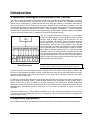
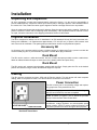
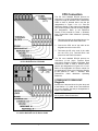
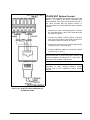
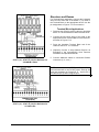
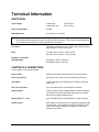
XX017-01-00
V1400X-IDL Intelligent Distribution Line Control
Vicon Industries Inc. does not warrant that the functions contained in this equipment will meet
your requirements or that the operation will be entirely error free or perform precisely as
described in the documentation. This system has not been designed to be used in life-critical
situations and must not be used for this purpose.
Copyright © 2002 Vicon Industries Inc. All rights reserved.
Product specifications subject to change without notice.
Vicon and its logo are registered trademarks of Vicon Industries Inc.
VICON INDUSTRIES INC., 89 ARKAY DRIVE, HAUPPAUGE, NEW YORK 11788
TEL: 631-952-CCTV (2288) FAX: 631-951-CCTV (2288) TOLL FREE: 800-645-9116
24-Hour Technical Support: 800-34-VICON (800-348-4266)
UK: 44/(0) 1489-566300 INFOFAX: 800-287-1207 WEB: www.vicon-cctv.com
Vicon Part No. 8009-8017-01-00 Section 11 Rev 702
Contents
CONTENTS.......................................................................................................................... 1
QUICK INSTALLATION....................................................................................................... 3
INTRODUCTION .................................................................................................................. 4
V1400X-IDL Intelligent Distribution Line Control ....................................................................................... 4
Compatible Equipment.................................................................................................................................. 4
How to Use this Manual ................................................................................................................................ 5
For Experienced Installers:....................................................................................................................... 5
For Novice Installers: ................................................................................................................................ 5
INSTALLATION ................................................................................................................... 6
INSTALLATION ................................................................................................................... 6
Unpacking and Inspection ............................................................................................................................ 6
Physical Installation ...................................................................................................................................... 6
Accessory Kit................................................................................................................................................ 6
Desk Mount .................................................................................................................................................. 6
Rack Mount .................................................................................................................................................. 6
Cabling............................................................................................................................................................ 6
Power Connection ........................................................................................................................................ 6
CPU Connection .......................................................................................................................................... 7
V1300X-DVC/V1300X-RVC Keypads ...................................................................................................... 7
V1400X-DVC System Console................................................................................................................. 9
Receivers and Domes ............................................................................................................................ 10
Terminal Block Applications................................................................................................................ 10
RJ-45 Connector Applications (Surveyor2000) .................................................................................. 11
OPERATION ...................................................................................................................... 13
Requirements and Characteristics ............................................................................................................ 13
Addressing ................................................................................................................................................. 13
Basics......................................................................................................................................................... 13
Operation Verification Procedure .............................................................................................................. 15
Input Devices.............................................................................................................................................. 15
Output Devices........................................................................................................................................... 15
CPU Control System Operation.................................................................................................................. 15
MAINTENANCE ................................................................................................................. 16
XX017-01-00 Rev 702 V1400X-IDL Intelligent Distribution Line Control
Contents • 1
Fuse Replacement ....................................................................................................................................... 16
SHIPPING INSTRUCTIONS............................................................................................... 17
REFERENCE ..................................................................................................................... 18
Cable Recommendations............................................................................................................................ 18
RS-422 Protocol ......................................................................................................................................... 18
Manual References for Associated Equipment ........................................................................................ 18
CPUs .......................................................................................................................................................... 18
Input Devices.............................................................................................................................................. 18
Output Devices........................................................................................................................................... 18
TECHNICAL INFORMATION............................................................................................. 19
ELECTRICAL.......................................................................................................................................... 19
CONTROLS & CONNECTORS.............................................................................................................. 19
OPERATIONAL ...................................................................................................................................... 20
MECHANICAL ........................................................................................................................................ 20
ENVIRONMENTAL................................................................................................................................. 20
2 • Contents
XX017-01-00 Rev 702 V1400X-IDL Intelligent Distribution Line Control
Quick Installation
Q
U
I
C
K
Q
U
I
C
K
I
N
S
T
A
L
L
A
T
I
O
N
I
N
S
T
A
L
L
A
T
I
O
N
XX017-01-00 Rev 702 V1400X-IDL Intelligent Distribution Line Control
Quick Installation • 3
Introduction
V1400X-IDL Intelligent Distribution Line Control
This manual covers the installation and operation of the Vicon V1400X-IDL Intelligent Distribution Line Control
(IDL). The V1400X-IDL will be referred to as the IDL throughout this manual. The installation procedures
should only be performed by a qualified technician using approved materials in accordance with national,
state and local wiring codes. Read these instructions completely before attempting installation. The IDL
complies with European Community EMC Directive 89/336. The product was subjected to the testing outlined
in European Normalization Standard EN 50081-1 (Electromagnetic Compatibility - General Emissions
Standard Part 1: Residential, Commercial and Light Industry), and EN 50082-1 (Electromagnetic Compatibility
- Generic Immunity Standard Part 1: Residential, Commercial, and Light Industry).
The IDL provides convenient connection of a Vicon-based
Control and Matrix System to 10 Vicon RS-422 Input or Output
Devices. Input or Output Devices will be referred to as “I/O
Device” throughout this manual. Control and Matrix Systems
will be referred to as “CPU” throughout this manual. The CPU
communicates with the IDL using standard Vicon RS-422
protocol through a 6- position Terminal Block connector labeled
CPU. Each I/O Device is connected using a 6-position Terminal
Block Station connector labeled STAT 1-10. This IDL provides
“intelligent control” via microprocessor- controlled circuitry that
can individually detect the status of each Station and isolate it
from the remaining stations. Thus, the IDL can prevent stations
that are locked, incorrectly wired or that have high noise levels
from interfering with other stations.
Figure 1
Basic System Setup
NOTE: RS-422 is an industry standard data transmission
protocol used for external device communication in this unit.
The IDL can be set to a non-intelligent mode by setting the rear panel switch to the DL position. When in the
DL mode, it simply passes commands. The IDL cannot detect the status of any connected stations or perform
initial baud rate locking. This mode is useful when, under certain sets of operating conditions, the station
detection cannot be performed.
I/O devices of different types cannot be connected to the same IDL unit. Each IDL unit must be dedicated to
Input or Output type devices. Figure 1 shows the Basic System Setup, comprised of an IDL, multiple Input or
Output Devices and a CPU. In addition to the IDL description, this manual also provides abbreviated
descriptions of I/O Device and CPU pin definitions. There are variations in the configuration of the IDL that are
described later. Abbreviated operation instructions for I/O Devices are provided to assist in the IDL’s
installation.
The IDL is available in two versions, Model V1400X-IDL (120 VAC) and Model V1400X-IDL-230 (230 VAC).
The 230 VAC model is equipped with the correct molded plug on the line cord. Both models are equipped with
surge protection circuitry.
Compatible Equipment
See the Manual References for Associated Equipment sub-section of the Reference Section of this manual.
4 • Introduction
XX017-01-00 Rev 702 V1400X-IDL Intelligent Distribution Line Control
How to Use this Manual
This manual was designed to provide the best overall instructions for the installation and operation of the
V1400X-IDL Intelligent Distribution Line Control. The graphics and terminology used in this manual have been
carefully selected to enable a clear and distinct understanding of the IDL and its components. This manual
has been formatted to present distinct methods of installation for experienced and novice installers.
For Experienced Installers:
Start at the Quick Installation sub-section of the Installation section to begin. Refer to the subsequent sections
of Installation, Operation and Maintenance for detailed descriptions of any method.
For Novice Installers:
Proceed to the Installation section and choose the appropriate schemes for Terminal Block connection. When
complete, proceed to the Operation section to apply power and verify operation. In addition, these sections
detail information on the use of peripheral equipment used, such as input and output (I/O) devices.
XX017-01-00 Rev 702 V1400X-IDL Intelligent Distribution Line Control
Installation • 5
Installation
Unpacking and Inspection
All Vicon equipment is tested and inspected before leaving the factory. It is the carrier’s responsibility to
provide suitable delivery. Inspect the cartons upon delivery and, if damage is present, make detailed notes on
the carrier’s bill. Then, obtain the carrier agent’s signature and file a damage claim as soon as possible.
Open the cartons and inspect the equipment for damage. Save the cartons and packing material. If damage is
present, contact the carrier and file a damage claim immediately. If the equipment must be returned to Vicon
for repair, follow the instructions in the Shipping Information Section of this manual.
Physical Installation
The IDL is designed for desktop use or for installation in an EIA standard 19-inch (483 mm) instrument rack.
During rack installation, it is important that approximately 1.75 inch (45 mm) of space is left between each
rack mount unit for ventilation. This spacing also provides easier access to equipment back panels.
Accessory Kit
An Accessory Kit is provided which includes 4 rubber bumpers, a replacement Fuse, a power cord with the
correct molded plug and 11 pre-terminated, 6 position Terminal Block plug-in Modules.
Desk Mount
The IDL can be used on a solid desk surface. Use the 4 rubber bumpers provided to make a stable base.
Attach an adhesive-backed bumper to each corner of the bottom surface and press firmly.
Rack Mount
The IDL can be rack mounted using hardware supplied with the Rack. Simply place the IDL at the desired
position and attach it using 4 screws. No additional support is required.
Cabling
The IDL must be connected to power, CPU and I/O Device controls. This sub-section will detail complete
cabling, which is comprised of Power, CPU and I/O Device Connection sub-sections.
Power Connection
The IDL is factory set for its operating voltage and requires
only proper use of the provided line cord.
NOTE: Do not apply power to the IDL until all cabling with
the CPU and I/O devices has been completed.
Verify that the correct fuse is installed in the Active Fuse
Holder as shown in Figures 1 and 2. Attach the provided
Power Cord to the Rear Panel Power Block.
NOTE: Vicon strongly recommends the use of line
conditioners, voltage regulators and uninterruptible power
supply systems (UPS) to prevent voltage fluctuations that
can affect operation and cause damage to the equipment.
Figure 2
Rear Panel Power Block
6 • Installation
XX017-01-00 Rev 702 V1400X-IDL Intelligent Distribution Line Control
CPU Connection
The IDL uses standard RS-422 protocol on
connector J11 (6-pin Terminal Block connector).
Prepare a length of Shielded, Dual Twisted-Pair
Cable to have 6 dressed wires. Use the pin
designations in Figure 3 for J11. See the
Reference Section of this manual for applicable
CPU Control System manuals denoting Keypad
pin designations. Refer to the Reference
Section of this manual for Table 1, Shielded,
Dual Twisted-Pair Cable Maximum Operating
Distances.
1. Fabricate the cable as described above. It is
recommended to label both cable ends.
2. Connect the CPU end of the cable to the
Keypads connector on the CPU.
3. Terminate the IDL wire ends of the cable
into the CPU (J11) Terminal Block and
press it into the Panel Connector.
Figure 3
J11 Pin Definition for CPU Cable
The IDL uses standard RS-422 protocol on
connectors J1-J10 (6-pin Terminal Block
connectors). Prepare a length of Shielded, Dual
Twisted-Pair Cable to have 6 dressed wires.
Use the pin designations in Figure 4 for J1-J10.
Refer to the applicable I/O Device manual for
pin designations. Refer to the Reference Section
of this manual for Table 1, Shielded, Dual
Twisted-Pair
Cable
Maximum
Operating
Distances.
V1300X-DVC/V1300X-RVC
Keypads
Connect the 6 dressed wires from the other end
of the Station 1 (J1) cable to the Terminal Block
(J1) on the Keypad. Use the pin designations in
Figure 5 for connection.
NOTE: STAT 1/J1 is used to represent any of
the 6- position Panel Connectors.
Figure 4
J1-J10 Pin Definition for I/O Device Cable
XX017-01-00 Rev 702 V1400X-IDL Intelligent Distribution Line Control
Installation • 7
1. Fabricate the RS-422 protocol cable as
described above. It is recommended to label
both cable ends.
2. Connect the Master Keypad end (open
wires) of the cable to the Screw Terminal
Block (J1) on the Keypad, as shown in
Figure 5.
3. Press the 6-position Terminal Block end of
the cable into the STAT 1/J1 connector.
4. (Optional) Connect Slave Keypads as
described in Vicon Installation and Operation
Manual X777.
5. Connect additional cables to consecutive
Station connectors (2, 3, 4, etc.).
NOTE: All unused station (STAT) port Terminal
Blocks are terminated with an end-of-line jumper.
Remove this small wire between the Response
In - signal (Pin 5) and Ground (Pin 4) when using
the port.
Figure 5
STAT 1 (J1) - STAT 10 (J10) Pin Definition for
V1300X-DVC/RVC Cable
8 • Installation
XX017-01-00 Rev 702 V1400X-IDL Intelligent Distribution Line Control
V1400X-DVC System Console
Connect the 6 dressed wires from the other end of the
Station 1 (J1) cable to the RJ-45 Termination Box
screw terminals. From here, use the RJ-45 to RJ-45 6foot cable, provided with the System Console, to
connect between the Termination Box and the System
Console.
1. Fabricate the cable as described above. Connect
the 6 dressed wires to the RJ-45 Termination Box
as shown in Figure 6.
2. Connect the System Console (RJ-45 connector)
end of the 6-foot cable to the RJ-45 connector on
the System Console, as shown in Figure 6.
3. Connect the other end of the 6-foot cable (RJ-45
connector) to the Termination Box.
4. Connect additional cables to consecutive Station
connectors (2, 3, 4, etc.).
NOTE: All unused station (STAT) port Terminal Blocks
are terminated with an end-of-line jumper. Remove this
small wire between the Response In - signal (Pin 5)
and Ground (Pin 4) when using the port.
NOTE: Refer to Vicon Instruction Manual XX090 for
information on daisy chaining additional System
Console units to the V1400X-DVC Master System
Console.
Figure 6
STAT 1 (J1) - STAT 10 (J10) Pin Definition for
V1400X-DVC Cable
XX017-01-00 Rev 702 V1400X-IDL Intelligent Distribution Line Control
Installation • 9
Receivers and Domes
For Terminal Block applications, connect the 6 dressed
wires from the other end of the Station 1 (J1) cable to
the Terminal Block on the appropriate device. Use the
pin designations in Figures 7-13 for connection.
Terminal Block Applications
1. Fabricate the RS-422 protocol cable as described
above. It is recommended to label both cable ends.
2. Connect the end (open wires) of the cable to the
appropriate Screw Terminal Block on the Receiver,
as shown in Figures 7-13.
3. Press the 6-position Terminal Block end of the
cable into the STAT 1/J1 connector.
4. (Optional) Connect a daisy-chained Receiver as
described in the corresponding Vicon Receiver
Installation and Operation Manual.
Figure 7
STAT 1 (J1) - STAT 10 (J10) Pin Definition for
V1200RLM-1 Cable
5. Connect additional cables to consecutive Station
connectors (2, 3, 4, etc.).
NOTE: All unused station (STAT) port Terminal Blocks
are terminated with an end-of-line jumper. Remove this
small wire between the Response In - signal (Pin 5)
and Ground (Pin 4) when using the port.
Figure 8
STAT 1 (J1) - STAT 10 (J10) Pin Definition for
V1319R Cable
10 • Installation
XX017-01-00 Rev 702 V1400X-IDL Intelligent Distribution Line Control
RJ-45 Connector Applications
(Surveyor2000)
For RJ-45 connector applications, connect the 6
dressed wires from the other end of the Station 1 (J1)
cable to the RJ-45 Termination Box screw terminals.
From here, use the provided RJ-45-to-RJ-45 6-foot
cable to connect between the Termination Box and
the RJ-45 connector on the appropriate device.
1. Fabricate the cable as described above. Connect
the 6 dressed wires to the RJ-45 Termination
Box.
2. Connect the Receiver (RJ-45 connector) end of
the 6-foot cable to the appropriate connector as
shown in Figure 13.
3. Connect the other end of the 6-foot cable (RJ-45
connector) to the Termination Box.
4. (Optional) Connect a daisy-chained Receiver as
described in the corresponding Vicon Receiver
Installation and Operation Manual.
5. Connect additional cables to consecutive Station
connectors (2, 3, 4, etc.).
Figure 9
STAT 1 (J1) - STAT 10 (J10) Pin Definition for
V1301R Cable
Figure 10
STAT 1 (J1) - STAT 10 (J10) Pin Definition for
V1311RB Cable
Figure 11
STAT 1 (J1) - STAT 10 (J10) Pin Definition for
V7UVS Cable
XX017-01-00 Rev 702 V1400X-IDL Intelligent Distribution Line Control
Installation • 11
Figure 12
STAT 1 (J1) - STAT 10 (J10) Pin Definition for
V15UVS Cable
Figure 13
STAT 1 (J1) - STAT 10 (J10) Pin Definition for
Surveyor2000 Cable
NOTE: The RJ-45 connector can be used instead of the Terminal Block on the Surveyor2000.
12 • Installation
XX017-01-00 Rev 702 V1400X-IDL Intelligent Distribution Line Control
Operation
The V1400X-IDL allows up to 10 I/O Devices to be connected to CPU-based Matrix systems. Since the
V1400X-IDL has panel indicators and no controls, individual I/O Devices are used for operation. Refer to the
Reference Section of this manual for I/O Device and CPU Instruction Manual numbers.
Requirements and Characteristics
Addressing
All I/O Devices’ addresses must be unique within an IDL unit (no two I/O Devices can be addressed 1, for
example). In the event that two or more Stations share the same address, the IDL will intermittently enable
and disable those individual Stations.
Basics
When Input Devices are connected, all can operate the CPU simultaneously. Any combination of Keypads or
System Consoles can be used with an IDL unit. When Output Devices are connected, all devices can be
operated by the CPU simultaneously. Any combination of different Receiver types can be used with an IDL
unit. Operation of the IDL is transparent to the user when proper monitor partitioning and camera seize control
is established on the CPU. The DL/IDL switch must be selected for intelligent mode prior to powering on the
unit. If the switch is toggled with power applied, the unit must be reset (temporarily unplug unit) for the mode
to be toggled. Refer to the Instruction Manual for the particular CPU control system for information on
establishing monitor partitioning and camera seize control.
Figure 14 shows the IDL with individual Station ports setup in 2 typical configurations using V1300XDVC/RVC Keypads and V1400X-DVC System Consoles as Input Devices.
The CPU can be controlled from
all Input Devices. However,
Keypad 2 can only control the
CPU when Keypad 1 (Master
Keypad) is powered on. All four
Input Devices must have unique
addresses or operation conflicts
will occur. Up to 10 Input Devices
can be connected to the IDL.
Figure 14
Typical System Setup With Input Devices
NOTE: Do not connect Input Devices (Keypads/System Consoles) and Output Devices (Receivers/Domes) to
the same IDL unit, as they will not operate correctly.
XX017-01-00 Rev 702 V1400X-IDL Intelligent Distribution Line Control
Operation • 13
Figure 15 shows the IDL with individual Station ports setup in a typical configuration using Receivers and
Domes as Output Devices.
The CPU can control all Output
Devices. Dome 1 can be operated even
when the V1311RB Receiver is
malfunctioning or not powered on
because this Receiver has a built-in
failsafe device. However, Receivers
that do not have built-in failsafe circuitry
must be powered on and operative for
successive daisy-chained devices to
operate. All Output Devices must have
unique addresses or operation conflicts
will occur.
Up to 10 Output Devices can be
connected to the IDL.
Figure 15
Typical System Setup With Output Devices
Figure 16 shows 3 IDLs daisy chained to a CPU. IDLs have 9 remaining STAT ports for I/O Devices, except
for the last unit which has 10 STAT ports available.
IDL 1 communicates directly with the CPU, passing
information from and to its connected I/O devices. IDL 2
communicates with the CPU through IDL 1, which
passes information from and to its connected I/O
devices. However, if IDL 1 is malfunctioning or is not
powered on, IDL 2 and IDL 3 will lose communication
with the CPU, because there is no failsafe circuitry
provided in the IDL. IDL 3 communicates as IDL 2 does,
through IDL 1.
NOTE: Do not connect Input Devices (Keypads/System
Consoles) and Output Devices (Receivers/Domes) to
the same IDL unit, as they will not operate correctly.
Figure 16
Typical System Setup With Daisy-Chained IDLs
14 • Operation
XX017-01-00 Rev 702 V1400X-IDL Intelligent Distribution Line Control
Operation Verification Procedure
Input Devices
•
Verify that all external equipment is powered-on and functional.
1. Setup all Input Devices in accordance with their corresponding Instruction Manuals, listed in the
Reference Section of this manual. The most important factors to setup are the addresses and baud rate.
The addresses must be unique for each input and the baud rate must be the same for all inputs.
2. Toggle the DL/IDL switch, on the rear panel, to the IDL position. Power-on the IDL by plugging it in. All
LEDs should blink once during the IDL’s power-on test. The POWER LED will illuminate solid. All Station
LEDs will illuminate solid individually. The IDL will detect the baud rate while it monitors the CPU. When
the baud rate has been detected (approximately 45 sec), it will blink the CPU LED to indicate the baud
rate and then illuminate it solid. One blink indicates 4800 baud, two blinks indicates 9600 baud and three
blinks indicates 19200 baud. After this, LEDs can be disabled based on line conditions.
Note: The CPU baud rate MUST be the same as the individual Stations for proper operation.
When a Station LED is disabled, the IDL has found that line to be corrupt and shut down that Station. If
that line becomes valid, the IDL will illuminate that LED. When the CPU LED is disabled, the
communication has failed with the CPU. However, the IDL will continue endlessly to attempt
communication with the CPU.
3. Call up consecutive Monitors and Cameras or Domes to verify communication with the CPU.
4. Repeat Monitor and Camera call up on all Input Devices to verify communication with the CPU.
Output Devices
•
Verify that all external equipment is powered-on and functional.
1. Setup all Output Devices in accordance with their corresponding Instruction Manuals, listed in the
Reference Section of this manual. The most important factors to setup are the addresses and baud rate.
The addresses must be unique for each output and the baud rate must be the same for all outputs.
2. Toggle the DL/IDL switch, on the rear panel, to the IDL position. Power-on the IDL by plugging it in. All
LEDs should blink once during the IDL’s power-on test. The POWER LED will illuminate solid. All Station
LEDs will illuminate solid individually. The IDL will detect the baud rate while it monitors the output
devices. When the baud rate has been detected (approximately 45 sec), it will blink the CPU LED to
indicate the baud rate and then illuminate it solid. One blink indicates 4800 baud, two blinks indicates
9600 baud and three blinks indicates 19200 baud. After this, LEDs can be disabled based on line
conditions.
Note: The baud rates of the output devices MUST be the same as the CPU for proper operation.
When a Station LED is disabled, the IDL has found that line to be corrupt and shut down that Station. If
that line becomes valid, the IDL will illuminate that LED. When the CPU LED is disabled, the
communication has failed with the corresponding output device. However, the IDL will continue endlessly
to attempt communication with the corresponding output device.
3. Setup one or more Input Devices in accordance with their corresponding Instruction Manuals, listed in the
Reference Section of this manual.
4. Call up each Output Device from each Input Device to verify proper connection to the IDL.
CPU Control System Operation
To properly control Cameras and Monitors on various CPU systems, it is necessary to setup monitor
partitioning and camera seize control on the CPU. Refer to the appropriate CPU Instruction Manual for
information on establishing monitor partitioning and camera seize control.
XX017-01-00 Rev 702 V1400X-IDL Intelligent Distribution Line Control
Operation • 15
Maintenance
This unit does not require any scheduled maintenance. If a unit does not operate and replacement of the fuse,
as described below, does not correct the problem, contact Vicon’s Service Department.
Fuse Replacement
If the unit is plugged into a known good outlet, and does not display an illuminated Power LED, replace the
Fuse. The Fuse is located in the Power Block at the rear of the unit, as shown in Figure 17.
1. Unplug the Line Cord from the outlet and the Power Block.
2. Remove the Power Block Fuse Cover and remove the Fuse from the Active Slot.
3. Replace the Fuse with one specified for the appropriate model, as stated in the Technical Information
Section of this manual.
4. Replace the Fuse Cover, connect the Line Cord and confirm that the Power LED illuminates.
Figure 17
Rear Panel Power Block
16 • Maintenance
XX017-01-00 Rev 702 V1400X-IDL Intelligent Distribution Line Control
Shipping Instructions
Use the following procedure when returning a unit to the factory:
1. Call or write Vicon for a Return Authorization (R.A.) at one of the locations listed below. Record the name
of the Vicon employee who issued the R.A.
Vicon Industries Inc.
89 Arkay Drive
Hauppauge, NY 11788
Phone: 631-952-CCTV (2288); Toll-Free: 1-800-645-9116; Fax: 631-951-CCTV (2288)
For service or returns from countries in Europe, contact:
Vicon Industries (U.K.) Ltd
Brunel Way
Fareham, PO15 5TX
United Kingdom
Phone: 44/(0)1489/566300; Fax: 44/(0)1489/566322
2.
Attach a sheet of paper to the unit with the following information:
a.
Name and address of the company returning the unit
b.
Name of the Vicon employee who issued the R.A.
c.
R. A. number
d.
Brief description of the installation
e.
Complete description of the problem and circumstances under which it occurs
f.
Unit’s original date of purchase, if still under warranty
3. Pack the unit carefully. Use the original shipping carton or its equivalent for maximum protection.
4. Mark the R.A. number on the outside of the carton on the shipping label.
XX017-01-00 Rev 702 V1400X-IDL Intelligent Distribution Line Control
Shipping Instructions • 17
Reference
Cable Recommendations
RS-422 Protocol
For all RS-422 protocol connections terminated in open wires or onto D-shell type connector use a 2conductor (twisted pair) shielded copper wire to make the connections. Refer to Table 1, Shielded, Dual
Twisted-Pair Cable Maximum Operating Distances.
CABLE TYPE
Belden 9406
Belden 9402
Belden 8723
Belden 8162
Belden 9729
Belden 9182
DISTANCE ft (m) max. NUMBER REQUIRED
1
5000 (1500)
1
5000 (1500)
1
8000 (2400)
1
15000 (4600)
1
15000 (4600)
2
25000 (7600)
For all RS-422 protocol connections
terminated in RJ-45 type (8 conductor)
cable, use a cable that does not exceed
6 ft (15 m). For wire runs longer than
this, use RJ-45 Termination Boxes
locally and longer runs with shielded
twisted-pair-cables in accordance with
Table 1.
Table 1
Shielded, Dual Twisted-Pair Cable
Maximum Operating Distances
Manual References for Associated Equipment
CPUs
V1200X
V1300X
VPS328/V1422
V1200X Series Transmitter/CPU
Microprocessor-Based Control System
VPS328/V1422 Digital Control, Installation/Operation
X379
X553
X826
Input Devices
V1300X-DVC/RVC
V1400X-DVC
Intelligent Remote Control Panels
System Console
X777
XX090
Output Devices
V1200R-LM
V1301R
V1311RB
V1319R
V15UVS
V7UVS
V5UVS
SUR2000
18 • Reference
Multiple Receiver
Outdoor Receiver
Universal Receiver
Dual Station Receiver
Omniscan Dome
Surveyor Mini Dome
Surveyor 99 Dome
Surveyor2000 Mini-Dome
X512
X506
X871
X825
X806
X971
X978
XX031
XX017-01-00 Rev 702 V1400X-IDL Intelligent Distribution Line Control
Technical Information
ELECTRICAL
Input Voltage:
V1400X-IDL:
V1400X-IDL-230:
Power Consumption:
9 Watts.
Heat Equivalent:
0.5 btu/min (0.13 cal/min).
120 V, 60 Hz.
230 V, 50 Hz.
Note: These figures represent the conversion of 100% of the electrical energy to heat. Actual percentage of
the heat generated will be less and will vary from product to product. These figures are provided as an
aid in determining the extent of cooling required for an installation.
Line Cord:
Standard 3-conductor SV No. 18 AWG cable with grounding
plug available in 120 and 230 VAC.
Fuse:
120 VAC: 5mm x 20mm, 0.25 A, slo-blo.
230 VAC: 5mm x 20mm, 0.125 A, slo-blo.
European Community
(CE) Standards:
EN 50081-1 generic emissions.
EN-50082-1 generic immunity.
CONTROLS & CONNECTORS
(refer to Figure 18 for panel locations)
Power (LED):
Red front panel LED illuminates when unit is powered-up.
Power (connector):
Rear panel 120 or 230 VAC grounded female connector.
CPU (LED):
Yellow front panel LED indicates CPU condition, intelligent
mode only.
CPU (J11 connector):
6-pin removable Screw Terminal Block connector.
Station (LEDs):
Green front panel LEDs indicate Station conditions. Stations
are ready for communication after initial power-on booting
has occurred (approximately 45 sec).
Station (STAT J1 - J10):
6-pin removable Screw Terminal Block for each connector.
DL/IDL Switch:
Slide switch on rear panel used to toggle the intelligent mode
on and off (DL = non-intelligent mode/ IDL intelligent mode).
Unit must be reset (temporarily unplugged) for the mode
change to take effect.
XX017-01-00 Rev 702 V1400X-IDL Intelligent Distribution Line Control
Technical Information • 19
OPERATIONAL
General:
Unit is operated using external devices (1 CPU and up to 10
I/O Devices). When set to intelligent mode (IDL), if one or
more Stations become corrupt (device locking, incorrect
wiring or excessive noise), the unit will shut down these
Stations and provide status indication on the front panel
LEDs. In addition, the CPU line will be monitored for status
and indication will be displayed accordingly with the front
panel LED.
Control Format:
RS-422 protocol data, full duplex operation at 4800, 9600 or
19200 baud.
MECHANICAL
Mounting:
Desk mount (bumpers provided) or Rack mount.
Dimensions:
Height: 1.7 in. (43 mm).
Width: 19.0 in. (483 mm).
Depth: 7.5 in. (191 mm).
Weight:
6.5 lb (2.9 kg).
Construction:
Steel chassis and cover.
Finish:
Black baked enamel chassis and cover.
ENVIRONMENTAL
Operating Temperature Range:
32 to 122°F (0 to 50°C).
Operating Humidity Range:
Up to 90% relative, noncondensing.
Storage Temperature Range:
-40° to 150° F (-40° to 65° C).
Storage Humidity Range:
Up to 90% relative, noncondensing.
Figure 18
Front and Rear Panel Views
20 • Technical Information
XX017-01-00 Rev 702 V1400X-IDL Intelligent Distribution Line Control
Vicon Industries Inc.
Corporate Headquarters
89 Arkay Drive
Hauppauge, New York 11788
631-952-CCTV (2288) 800-645-9116
Fax: 631-951-CCTV (2288)
!Infofax: 800-287-1207
Vicon Europe
Headquarters
Brunel Way
Fareham, PO15 5TX
United Kingdom
+44 (0) 1489 566300
Fax: +44 (0) 1489 566322
Brussels Office
Planet II - Unit E
Leuvensesteenweg 542
B-1930 Zaventem
Belgium
+32 (2) 712 8780
Fax: +32 (2) 712 8781
Far East Office
Unit 5, 17/F, Metropole Square
8 On Yiu Street, Shatin
New Territories,
Hong Kong
(852) 2145-7118
Fax: (852) 2145-7117
Internet Address: www.vicon-cctv.com