1
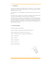
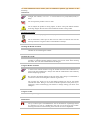
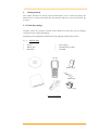
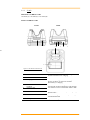
Empower the Bar Code User’s Manual PA-20 Portable Data Terminals DOC NO. UM-P2005-01 Sep. 2009 Version 1.1 CAUTION: This user’s manual may be revised or withdrawn any time without prior notice. Copyright 2008, Argox Information Co., Ltd. All rights reserved. This manual may not, in whole or in part, be copied, photocopied, reproduced, translated or converted to any electronic or machine readable form without prior written consent of Argox. Limited warranty and disclaimers By opening the package of this product you agree to become bound by the liability and warranty conditions as described below. Under all circumstances this manual should be read attentively before installing and or using the product. In no event, Argox will be liable for any direct, indirect, consequential or incidental damages arising out of use or inability to use both the hardware and software, even if Argox has been informed about the possibility of such damages. A series number appears on all Argox products. This official registration number is strictly related to the device purchased. Make sure that the serial number appearing on your Argox device has not been removed. Servicing by our service department can only be carried out under warranty. All Argox products are warranted for the legal warranty period after purchase, covering defects in material and workmanship. Argox will repair or, at its opinion, replace products that prove to be defective in material or workmanship under proper use during the warranty period. Argox will not be liable in case modifications are made by the customer. In such case the standard repair charge will be applicable. The standard charge for repair will also be applicable in case no defect is found at all. These rules also apply for products that are still under warranty. Therefore, you are advised to have the product specifications always at hand. Trademarks used are property of their respective owners. The general use and functioning of the terminal together with the cradle will be described in this manual. The exact behaviour of the terminal depends on the user application that is running. For instructions about applications please consult the documentation of that software. Please read this manual carefully before using the terminal, to maximize the efficiency of this terminal. II Table of Content 1. INTRODUCTION ..................................................................................................1 1.1 ABOUT THIS MANUAL .....................................................................................1 1.2 USER AND PRODUCT SAFETY .........................................................................2 1.3 SPECIFICATIONS .............................................................................................4 2. GETTING STARTED ...........................................................................................6 2.1 CHECK THE PACKAGE ....................................................................................6 2.1.1 PDT Package .......................................................................................6 2.1.2 Cradle Package ....................................................................................7 2.2 DETAILED VIEW .............................................................................................8 2.2.1 Terminal ...............................................................................................8 2.2.2 Cradle ..................................................................................................9 2.3 ASSEMBLY .....................................................................................................10 2.3.1 Terminal .............................................................................................10 2.3.2 Cradle ................................................................................................11 2.4 INSTALLING, REPLACING AND CHARGING BATTERIES ...............................12 2.4.1 Installing / Replacing the Battery Pack..............................................13 2.4.2 Charging the Battery Pack with Cradle .............................................15 2.5 INSTALLING IN A SYSTEM .............................................................................16 3. OPERATION OF THE TERMINAL .................................................................17 3.1 SOFTWARE DESCRIPTION .............................................................................17 3.2.1 LCD Screen Description ....................................................................18 3.2.2 Keypad Description............................................................................19 3.2.3 Power Management ...........................................................................21 4. CONFIGURATION .............................................................................................22 4.1 SYSTEM MENU ..............................................................................................23 4.1.1 Communication ..................................................................................23 4.1.2 File Manager .....................................................................................23 4.1.3 Setting ................................................................................................23 4.1.4 Test .....................................................................................................24 4.1.5 Information ........................................................................................24 4.2 SUPERVISOR MENU.......................................................................................25 4.2.1 Communication ..................................................................................25 4.2.2 Format Disk .......................................................................................25 4.2.3 Setting ................................................................................................25 4.2.4 Barcode ..............................................................................................25 4.2.5 Information ........................................................................................26 4.3 APPLICATIONS ..............................................................................................27 4.4 UPLOAD /DOWNLOAD BY PTFILE MANAGER..............................................28 5. SCANNING ..........................................................................................................29 5.1 HOW TO READ THE BARCODE .......................................................................29 5.2 BARCODE READING PROBLEMS ....................................................................30 6. COMMUNICATIONS.........................................................................................31 6.1 CRADLE COMMUNICATION ..........................................................................31 6.2 BLUETOOTH COMMUNICATION ...................................................................32 7. CABLE PIN-OUT ................................................................................................34 III 7.1 RS232 CABLE FOR CRD-22 CRADLE (9-PIN TO 9-PIN) ...............................34 7.2 USB CONNECTOR FOR CRD-22 CRADLE ....................................................34 8. TROUBLE SHOOTING .....................................................................................35 8.1 8.2 8.3 8.4 GENERAL CHECKS........................................................................................35 COMMUNICATION PROBLEMS ......................................................................36 READ OPERATION PROBLEMS .....................................................................37 TERMINAL PROBLEMS..................................................................................38 IV 1. Introduction The PA-20 series portable data Terminal (PDT) is well suited for a variety of portable applications. It has a built-in CCD scanning engine that can scan all popular bar code labels at varying distance (up to 13 inches). User’s applications can be downloaded to the terminal to adapt the terminal to the user’s situation. The operation power is supplied by the main battery (rechargeable Li-Polymer battery pack for Terminal, and a rechargeable Li-ion battery pack for Gun configuration). The CRD-22 cradle is a communication and charging station for data transmission between the (host) terminal system and the terminal. It communicates with the terminal through RS232 serial or USB interface. The CRD-22 cradle will charge the rechargeable battery pack in the terminal through the electrical contacts. And it also provides an extra charging slot for a spare battery pack if necessary. 1.1 About this Manual The chapters contained in this manual are: Chapter 1: Introduction – Presents general information about the PA-20 Chapter 2: Getting started – Describes basic use of the PA-20 Chapter 3: Operating the terminal – Describes customizing the PA-20 Chapter 4: Configuration Chapter 5: Scanning Chapter 6: Communication Chapter 7: Cable Pin-out Chapter 8: Trouble Shooting 1 1.2 User and Product Safety Never use strong pressure on the screen or subject it to severe impact, as the LCD panel can crack and possibly cause personal injury. If the LCD panel is broken, never touch the liquid inside, for such contact can irritate the skin. Although the PA-20 mobile terminal meets IP54 standards for water and dust resistance, avoid prolonged exposure to rain or other concentrated moisture. Conditions exceeding IP54 standards could result in water or other contaminants entering the PA-20. Use only the approved AC Adapter with the PA-20. Use of an unapproved AC Adapter could result in electrical problems, or even cause a fire or an electrical shock to the user. Be sure that only authorized suppliers are allowed to disassemble and reassemble the device. If the device or parts are damaged due to wrong handling, the product and parts warranty is void. Always make back-up copies of all important data. This is easily done using single cradle (optional) to transfer data to the terminal. The manufacturer is not liable for any data damage or data loss caused by deletion or corruption while using this device, or due to a drained battery. Lithium-ion battery packs may get hot, explode, ignite and/or cause serious injury if abused. Please follow the safety warnings listed below. Warnings: Do not place the battery pack in fire or heat the battery. Do not install the battery pack backwards so the polarity is reversed. Do not carry or store battery pack together with metal objects. Do not pierce the battery pack with nails, strike the battery pack with a hammer, step on the battery pack or otherwise subject it to strong impacts or shocks. Do not solder directly onto the battery pack. Do not expose battery pack to liquid, or allow the battery contacts to get wet. Do not disassemble or modify the battery pack. The battery pack contains safety and protection devices, which, if damaged, may cause the battery pack to generate heat, explode or ignite. Do not discharge the battery pack using any device except for the specified device. When it is used in devices other than the specified devices, the battery pack can be damaged or its life expectancy reduced. If the device causes any abnormal current to flow, it may cause the battery pack to become hot, explode or ignite and cause serious injury. In the event the battery pack leaks and fluid gets into the eyes, do not rub the eyes. Rinse well with water and immediately seek medical care. If left untreated, the battery fluid could cause eye damage. 2 To avoid malfunctions and to ensure years of trouble-free operation, pay attention to the following: General Use Do not expose the mobile terminal to areas subject to extreme heat such as direct sunlight, near a heater, or in a car – or in areas that are very cold, humid, moist, or dusty. Do not expose the product to rain or water Do not subject the product to strong impact, or throw or drop the mobile terminal from large heights. Do not allow other mechanical shocks to the product. Cleaning Instructions Clean the exterior by wiping it with a soft, dry cloth. Do not use much water. Do not use thinner, white spirit or other solvents. These can discolor the case and the keys and it has a negative effect on the lifetime of the keys. Cleaning the Mobile Terminal Clean the scan window periodically for better reading performance, but pay attention to not scratching the window Cleaning the Cradle Avoid touching the contacts in the cradle. The contacts must stay as clean as possible to maintain optimal charging capacity. Do not use water when cleaning the cradle. This can cause malfunction of the chargers. Using the Mobile Terminal Avoid temperature changes. Sudden temperature changes can cause condensation to form on the mobile terminal. Using the mobile terminal while condensation is present can cause malfunction. Always wait until the condensation clears naturally before attempting operation. Do not leave the mobile terminal in an area where static charge is accumulated or near devices where electromagnetic emission is generated. Do not place any object on top of the mobile terminal. Do not lay the mobile terminal face down. Doing so can cause accidental operation of the power key or [ENT] key, which can discharge your batteries or change settings you do not want changed. Using the Cradle Do not place any product other than the PA-20 mobile terminal in the cradle. Maintenance There are no user-serviceable parts inside the mobile terminal or the cradle. So do not try to take it apart. The manufacturer will not be liable for any damage caused by customers. In case of a malfunction that can not be solved by the troubleshooting instructions in this manual, please consult our service department. 3 1.3 Specifications Model PA-20 PA-2010 Wireless Communication WPAN General Characteristics OS Bluetooth Class2 Proprietary CPU ARM9 Core 533MHz RAM 16MB FLASH 20MB Display 2.4” LCD TFT Transmissive, 240 x320 QVGA 65K colors LED Keypad Alert Power Operating power Working hour (scan / 5 sec) Data retention Blue, Green and Red 29 Numeric Buzzer, Vibrator Terminal: Rechargeable 3.7V 1950mAh Li-Polymer Battery Gun type: Rechargeable 3.7V 5000mAh Li-ion Battery > 18 hours (1950mAh) > 15.5 hours(1950mAh) > 47 hours (5000mAh) > 40 hours(5000mAh) 15-min data retention Data retention 2.5 days Scanner Scanner system Long Range CCD scanner 2048 pixels Resolution 0.127mm (5mil) at PCS 90% Depth of field 600mm (code 39, 20mils, PCS 90% Scanning rate 400 scans /sec Readable barcode Code 11, Code 39, Code 93, Code 128, Codabar, EAN-8, Ean13, Industrial-2/5, Interleaved-2/5, Standard-2/5, MSI/Plessey, UK/Plessey, Telepen, UPCA, UPCE, Matrix 2/5, China Post, GS1 databar, Italian Pharmacy , 4 Environment Operating Temperature -10℃ to 60℃ / 14℉ to 140℉ Storage Temperature -20℃ to 70℃ / -4℉ to 158℉ Humidity Impact resistance Electrostatic discharge EMC Regulation Developing tools Software Program Language Operating: Non-condensed 10% to 90% Storage: Non-condensed 5% to 95% 1.2M/4ft (Terminal) 0.9M (Cradle) IP54 +/- 15 KV air discharge +/- 8 KV direct discharge FCC, CE, BSMI, CCC Windows based application generator: Architect Software Development Kit (SDK) C language(SDK), Basic(Architect) Accessory Charging & Communication Cradle Pistol Grip, C&C cable, Holster 5 2. Getting Started This chapter describes the PA-20 physical characteristics, how to install and charge the batteries, how to remove and replace the strap assembly and how to start the PA-20 for the first time. 2.1 Check the package Carefully remove all protective material from around the PA-20 and save the shipping container for later storage and shipping. Depending on the configuration ordered, the PA-20 shipping container may include: 2.1.1 PDT Package PA-20 Battery pack Hand strap Power supply Quick Reference Guide CD ROM PA-20 CD ROM Battery pack Hand strap Quick Reference Guide Power plug Power supply Figure 2-1 PDT Package 6 2.1.2 Cradle Package CRD-22 USB cable USB cable Cradle Figure 2-2 Cradle Package Inspect the package contents for damage. If any item is missing or damaged, please contact the Argox Technical Support Center immediately. 7 2.2 Detailed View 2.2.1 Terminal Dimensions of Terminal 168.8mm (L) x 70.1mm (W) x 34.0mm (H) Details of Terminal Left side Front Right side Back 2 3 9 4 5 Top 8 6 Bottom 10 1 Figure 2-3 Terminal 1 Reading Window 2 LED Indicator 3 4 LCD Display Stroke keys 5 Reset switch 6 7 Hand strap hook Buzzer 8 9 Main battery compartment Main battery compartment lock 10 Power Contacts Optical beam of LED for barcode reading will be emitted from here Can be used to indicate results, for example bar code reading / status of communication For displaying information and battery status A total of 29 keys are provided to turn power ON and OFF and for other operations. Use a paper clip or other thin object to press the RESET switch located inside the hole. Used to install the hand strap Outputs operation confirmation tones. Take care to avoid blocking the buzzer holes and reducing output sound volume. Never insert any thin, pointed object into the buzzer holes. Doing so can caused malfunction. Holds main batteries Locks the main battery compartment cover in place. Terminal power is automatically cut if the cover is removed. The terminal is used to supply power from Cradle. 8 7 2.2.2 Cradle Dimensions of CRD-22 Cradle 162.4mm (L) x 112mm (W) x 93.9mm (H) Details of CRD-22 Cradle Front Back 1 2 3 4 8 7 6 port 5 Figure 2-4 The Details of the CRD-22 1 Terminal Slot 2 3 Power LED Indicator Charging LED Indicator 4 5 Power and Communication Contacts Charging Slot 6 RS-232 Socket 7 USB Socket 8 DC Input Socket Put the terminal on the cradle through this slot for data transmission or charging Power indicates Indicates the charge status of the battery. Green: no battery or charging complete Red: battery is charging To connect with the multiple function socket on the terminal for data transmission and charging For charging a spare rechargeable battery pack For connecting to PC serial port through Argox RS232 cable For connecting to PC USB port through a standard USB cable Input for AC adapter 9 2.3 Assembly Follow the next steps to make your terminal ready for installation in a system that is described further in the manual. 2.3.1 Terminal The hand strap protects the Terminal from being damaged as a result of it being dropped by mistake during movement. Follow the procedure below to attach the hand strap. To attach the hand strap 1. Fix the small cord of the strap around the pillar of the terminal. 2. Insert the handle of the strap in the thin loop. 3. The strap is fixed to the terminal. 4. Hold the hand strap around the wrist when carrying the terminal. 1 2 Figure 2-5 Hand strap Important: Do not swing the terminal around Start with a full battery 1. To be sure of proper operation, it is advised to start with a full battery, charge the battery pack according to the instructions in the next chapter. 2. Click the battery pack into the terminal as instructed in the next chapter. 10 2.3.2 Cradle Power Connection 1. Attach the DC jack of the AC adapter into the socket of the cradle. Then connect the AC adapter to the mains outlet. The LED on the cradle turns green. Battery Charging 1. 2. When the PA-20 terminal with the rechargeable battery pack is placed in the cradle, the LED on the cradle turns orange first and turns green at once then it starts to charge the terminal. When the PA-20 terminal was removed from the cradle, the LED on the cradle turns orange first and turns green at once. Spare Battery Charge LED Figure 2-6 Batter Charging Terminal on cradle Take notice that the PA-20 cradle is designed for the PA-20 terminal. No other type of terminal can be placed into this cradle. This can cause damages to the connector on the cradle. Figure 2-7 charging 11 2.4 Installing, Replacing and Charging Batteries Wrong use of batteries might cause serious damage to the terminal or to the cradle. In order to avoid damage, it is very important to take notice of the instructions. Caution: Insert a fully-charged battery pack before use of the terminal. Never remove the main batteries while the terminal is turned on. Doing so may lose data in the terminal. Use only recommended batteries. When other batteries are used, defects or other problems can occur. Before installing (new) batteries, please make sure you are using the recommended batteries. Use the right charger for batteries. The rechargeable battery pack form Argox can be charged in the cradle when either it is in the terminal or alone in the charging slot in the back of the cradle. The life of a battery pack is limited, and charging a battery pack causes it to gradually lose its ability to maintain a charge. If your battery pack requires frequent charging, it probably means it is time to purchase a new one. Strictly follow the instructions for installing, charging, and removing the batteries. The products are not warranted for damage, defects, malfunction, or loss of data, resulting from incorrect use of batteries. Required batteries: The terminal needs both main battery and backup battery for operation. Main Battery Terminal: Rechargeable 3.7V 1950mAh Li-Polymer Battery Gun type: Rechargeable 3.7V 5000mAh Li-lon Battery 12 2.4.1 Installing / Replacing the Battery Pack How to install or replace the main battery in the terminal 1 Slide the main battery compartment cover lock to the FREE position and remove the cover 2 Load a lithium-ion battery pack into the main battery compartment in the direction shown in the figure 3 Attach the battery compartment cover to the terminal and slide the main battery compartment cover lock to the LOCK position. Figure 2-7 Installing / Replacing the Main Battery Note: Please follow the above procedure in reverse to reassemble the battery cover. Be sure to turn the terminal OFF before you do this. 13 How to install or replace the main battery in the gun grip 1 Attach the battery compartment cover to the terminal and slide the main battery compartment cover lock to the LOCK position. 2 Attach the battery compartment cover to the terminal and slide the main battery compartment cover lock to the LOCK position. Figure 2-9-1 Installing /Replacing The Gun Grip Battery Figure 2-9-2 Installing /Replacing The Gun Grip Battery 14 2.4.2 Charging the Battery Pack with Cradle Figure 2-10 Charging with Cradle How to charge Argox rechargeable battery pack in the cradle 1. Make sure that the Argox rechargeable battery pack is inserted in the terminal. If the terminal with the battery pack is placed in the cradle, the LED on the cradle will turn Orange first and turn to Green at once. When the terminal is placed in the cradle, the rechargeable battery pack will be charged automatically. 2. If you have a spare Argox battery pack, you can replace the empty battery pack with a full battery pack for continuous terminal operation. And put the empty battery pack in the charging slot of the cradle. The LED (CHG) on the cradle will turn to Red in flashing and turn to Green again when the battery is full. When to replace or recharge the main battery There are two conditions that you need to replace the main battery. 1. As soon as possible after the battery indicator or “Battery Low” tip appears on the display. 2. Before using the terminal again, in case it has not been used for an extended period. Caution: Ambient Temperature Ranges for the Battery Pack Temperature ranges for battery pack use in the terminal, charging, and storage is specified below. Temperatures outside these ranges create the danger of deterioration of battery pack performance and shortening of its service life, as well as fluid leakage and heat generation. Operating Temperature: -20 to 50℃ Charging Temperature 0 to 40℃ Storage Temperature: -20 to 60℃ If the battery pack charge indicator does not light during charging, remove the battery pack and then re-attach it. If this does not solve the problem, it means that the battery pack is defective and needs to be replaced. Use only the specified battery pack. Battery packs naturally discharge even when they are not loaded in the terminal. Use a battery pack as soon as possible after charging it. For best charging results, keep the cradle, terminal and battery pack contacts clean by periodically wiping them off with a cotton swab or dry cloth. 15 2.5 Installing in a System Notes: Exercise caution at all times when working with AC-powered equipment. Turn off your devices before installation. Because of the special pin-out of the connectors, use the cables supplied by the manufacturer. Do not modify the cable provided by the manufacturer. If you need a special cable for some cases, contact your supplier to purchase the right cables or technical support. System Connection (Data Communication) The PA series portable data terminals let you link to a host terminal through the CRD-22 cradle for data communication. The CRD-22 cradle provides two methods for data transmission: through an RS-232 cable (9pin connector for PC and 9-pin connector for terminal) and through a USB cable. Figure 2-9 System Connection Notes: When both RS-232 and USB cables are connected between the CRD-22 cradle and host terminal, PA-20 can assign either USB or RS-232 interface for data transmission. 16 3. Operation of the Terminal 3.1 Software Description The functionality of the terminal is determined by software, e.g. user application that is running on the terminal. Usually, the terminal is not equipped with software. There are only some simple functions can be tested (like scanning test, com port test). Tools provided by Argox for developing a user application are: Software Development Kit (SDK); Architect, and C library for handheld terminal The user application must be downloaded from the PC into the terminal. You can use the cradle between the terminal and the PC. A program (PTFileManager) on the PC will send the user application to the terminal, where it is stored in NAND Flash. When the functionality of the terminal is defined by the application, it is ready for operation. In a typical application, you will press the trigger key and scan a bar code label as described in the next paragraph. Scanned data and data entered from the keypad are stored in the terminal’s RAM. The user application can use this data in subsequent steps. The collected data can be transmitted to the PC further processing through the cradle. 17 Hardware Description 3.2.1 LCD Screen Description The LCD screen of the PA-20 data terminal shows program settings, operational procedures, calculation results and other information. Display Area 240 dots (H) *320 dots (V) 18 3.2.2 Keypad Description The PT Series keypad consists of 29 rubber keys including one SCAN key. 1 2 3 4 6 7 5 Figure 3-1 Keypad Description 1. Scan key Scan a bar code read operation 2. Cursor key This Cursor key navigates among applications. 3. 10-key pad The function of these keys depends on whether the Terminal is in the character input mode of the number input mode: Character input mode: Input alphanumeric and symbols. Number input mode: Inputs the numbers 0 to 9 and the decimal point. 4.ENT key Registers input 5.Power key Turns power ON and OFF. 6.Function keys Keys that can be assigned any function. The following are the initial functions assigned to these keys. F1 (-) Inputs the minus (-) sign. F2 (SP) Inputs a space. F3 (DEL) Deletes a character. F4 (BL) Turns the key lights ON and OFF F5 Increases buzzer volume F6 Increases LCD backlight 19 P1 Decreases Buzzer volume and program 1 (for user SDK define) P2 Decrease LCD backlight and program 2 (for user SDK define) 7.Control keys ESC Escape key SFT Switches between the character input mode and the number input mode. [abc][ABC] lit on the LCD screen indicates the character input mode. When [123] is lit, the terminal is in the number input mode. BS Backspaces and deletes one character. 20 3.2.3 Power Management Auto-Off: When the auto-off timer at Setting\ Environment\Auto off Timer. On\Auto-Off was set; the terminal will turn off automatically when it is idle for a time period equal to the set timer. Battery Low Status : While under power on condition, if the battery capacity is low, the system will show a warning message and then turn off after a set timer. Recharging Status: While under power on condition, if you put the terminal on the cradle, the battery indicator on the LCD display will show on charging status. 21 4. Configuration This section mainly describes how to configure the PA-20 Series terminal, regarding system configurations and program download. When a menu is displayed, you may select an item by either of the following ways: Using the [UP] and [DOWN] keys to move the highlight bar Pressing the number key that corresponds to the item number Item No. (Shortcut keys) 123 System Menu 1. Communication 2. File Manager 3. Setting 4. Test 5. Information Menu Title On each screen, the last column displays status icons, such as: The battery icon indicates the current power status. The input mode and function mode, which are contrlled by the [SFT] key and [FN] key(F1~F6) separately. To return to a previous page or menu, you many press [ESC] or follow the on-screen instructions. PA-20 is set up such a way that there are several operating modes. The system of terminal may operate in various modes for different purposes. There are two operation menus for the users: 1. System Menu: user can set general system configurations. 2. Supervisor Menu: the supervisor menu is protected with password checking to prevent unauthorized personnel from changing the system configuration. 22 4.1 System Menu How to access the System Menu? 1. Turn off the PA-20 terminal. 2. Press [3] + [9] + [Power] 4.1.1 Communication Communication > File Transfer Communication > Interface COM USB Communication > Baud Rate 115200bps /57600 bps/ 38400 bps /19200 bps/ 9600 bps /4800 bps 4.1.2 File Manager File Manager > C Property File Manager > D Property File Manager > DIR Disk 4.1.3 Setting Setting > Environment System Settings LCD BL Timer Key BL Timer Auto Off Timer Power On Key Click Vibration Status Bar Default Values 20s 20s 180s Resume Enable 0.1s Enable Setting > Language System Settings Language Default Values English Setting > Date & Time Now Date & Time year/month/day hour:minute:second New Date & Time year/month/day hour:minute:second 23 4.1.4 Test Test > Memory Test Test the data memory (DDRRAM), and the results will be shown on the screen. To stop and exit the test, press [ESC] Notes: The data saved on C:\ maybe lose after the memory test. Test > Buzzer Test Test the buzzer with different frequency / duration combination. Press [ENT] to start. To stop and exit the test, press any key. Test > LCD & LED Test Test the LCD display and LED indicator. Press [ENT] to start. To stop and exit the test, press any key. Test > keypad Test Test the rubber keys. Press any key and its corresponding character will be shown on the screen. To stop and exit the test, press [ESC]. Test > Com Port Test After a Com Port cable is connected properly, run “Hyper Terminal “ on your computer and start this test on your terminal. Test > Read Test Test the reading performance of the scanner. Press [SCAN] to start. To stop and exit the test, press any key. 4.1.5 Information Here provides important system information to help diagnose the system. IPL BOOT Kernel Scanner SN DefLang IPL Version BOOT Version Kernel version Scanner version A serial number assigned to the terminal Default language 24 4.2 Supervisor Menu The Supervisor Menu is generated by a powerful utility, which offers an interface for engineers (programmers or system integrator) to view system information, change the congiguration parameter, download programs and run diagnotics. This memu is designed for engineering tests and maintenance ONLY. For this reason, the Supervisor Menu provides password protection to prevent unauthorized users from accidentantlly changing system settings. How to access the Supervisor Menu? 1. Turn off the PA-20 terminal. 2. Press [1] + [3] + [0] + [Power] Note: 4.2.1 The Supervisor Menu is NOT for the use of any end users. The system password helps ensure system safety and integrity. Communication File Transfer Upgrade Interface Baud Rate 4.2.2 Format Disk Format C Format D 4.2.3 Setting You can change the default setting here. System Setting Equipment ID Password BIOS default 4.2.4 Default Values 0000 00000 Barcode Reading Test Indication System Setting LED Beep Default Values Enable Enable 25 Code ID System Setting Transmission Position Default Values Disable Disable Invert Image System Setting Invert Image Default Values Disable Preamble Postamble Code Config. Group 1 System Setting Code-11 Code-39 Code-93 Code-128 EAN-8 EAN-13 UPC-A UPC-E Disable Enable Disable Enable Enable Enable Enable Enable Default Values System Setting Industrial 25 Interleaved 25 Standard 25 MSI-Plessey UK-Plessey RSS 14 RSS Limited RSS Expanded Disable Enable Disable Disable Disable Disable Disable Disable System Setting CODABAR Telepen Matrix 2 of 5 China Post Italian pharmacode Disable Disable Disable Disable Disable Group 2 Default Values Group 3 Default Values Scanner FW Upgrade Scan key power on 4.2.5 Information IPL BOOT Kernel Scanner SN HW Ver. HW Int. DefLang IPL Version Boot Version Kernel version Scanner version A serial number assigned to the terminal Hardware version (PCBA) Hardware internal version Default language 26 4.3 Applications Function User can execute a designed program and proceed to collect and store data based on the demands in the program. This program needs to be generated by SDK and downloaded with relative files into terminal by FileManager. The terminal can store only one program. You can set in the program whether the collected data needs to be stored or not. If it needs to be stored, all the data files will be stored in C:\Data directory. Users can edit the data file in System Tools\Edit Data. Every user program is a Project. It includes the following files: Item Ext. file name Stored directory Program ABP D:\Program Lookup file DAT D:\Lookup Fonts CFT D:\Fonts Data DAT C:\Data Description Main program in Architect Project When user collects and confirms the collected data to terminal, the system will search the specified lookup file for any matched string, and replace it with the data shown on the display. SFT is the system font and CFT is downloaded font. For detailed specification, please see in Hardware description (4.2.1, page 19).(System Font has been built-in) The stored area of collected data in program PS. Sub file name only support 3 chars. Note: Argox will not be liable for any damage or system crash by improper operations of firmware change without advice or instruction from Argox or Argox’s authorized support center. 27 4.4 Upload /Download by PTFile Manager The way to upload /download by supervisor menu will need the operator to set the terminal to supervisor menu by selecting Transfer in supervisor menu or calling system function n application program. PA20 can be instructed to process data communication by PTFileManager through built-in MULTI communication protocol. After linking the terminal to a PC/ host through RS232 / USB interface a communication program running on host first sens a few of dummy bytes to the terminal and delay for about 500 mini-second to remotely wake up the unit. Then the program can send out a data pack of a remote PTFileManager that matches the MULTI protocol to the terminal and instruct the terminal for certain process. For instance, the terminal will automatically execute the system routine to upload a file after receiving the valid “File upload” PTFileManager. Meanwhile the program running on the host should follow the control flow of MULTI protocol and process to receive the data. 28 5. Scanning Note: Observe handling precautions. Make sure the mobile terminal is installed according to instructions. Never remove the main batteries or battery pack while the mobile terminal is turned on. Doing so can cause loss of data in the mobile terminal. Avoid looking directly into the LED light beam emitter, or pointing the LED light beam directly into someone’s eyes. Fit the bar code in the LED light beam from margin to margin and pass the scanner downward over the bar code, as shown in the scan position illustration Good read scan position Incorrect read scan positions 5.1 How to read the barcode The scanning sequence is defined by the user’s application. A typical sequence is: Press the PW key to turn power on. Get into the System Tools\Scan Test and you will find the message on the display: <ScanTest> Type: Len: Point the terminal to the barcode and press the Trigger key . Point the LED lightbeam to barcode as shown in the scan position illustration. The barcode will be read and the reading results will be indicated. A “Good Read” means that the scanner has effectively recognized and decoded the bar code. In most cases, the application program will provide an indicator signal or a buzzer signal to indicate a good read to the user. When the read is incorrect you can try again, paying attention to the instructions in this chapter. 29 When reading a small bar code, decrease the distance between the terminal and the bar code. For larger bar codes, position the terminal so that the bar code fits into the LED light beam. When reading a very high density bar code, decrease the distance between the terminal and the bar code. For a low density bar code, increase the distance between the terminal and the bar code. 5.2 Barcode reading problems When the barcode can not be read, try the following: Change the angle between the bar code and the terminal. Change the distance between the bar code and the terminal. If the bar code is larger than the LED light beam, try moving the terminal a bit further away from the bar cod 30 6. Communications 6.1 Cradle Communication The CRD-22 cradle provides two methods for data transmission: through an RS-232 cable (9pin connector for PC and 9-pin connector for collector) and through a USB cable. Figure 6-1 When both RS-232 and USB cables are connected between the CRD-22 cradle and host terminal, PA-20 can assign either USB or RS-232 interface for data transmission. 31 6.2 Bluetooth Communication The Bluetooth interface support SPP mode (Serial port profile) can be used to connect a Bluetooth compatible printer. Data can be transferred if the terminal is located within ten meters of the target device (while nothing is blocking the signal). Set up instructions 1. Press 1+3+0+power key at the same time and PA20 will enter supervisor menu. The password default is 00000. 2. Select 5.Bluwtooth -> 1.Setup, it will enter Bluetooth setting menu like Figure 6-2 Figure 6-2 3. The menu includes basic Bluetooth setting. (1) Device Name: name of PA20 Bluetooth device. (2) Pin Code: set Bluetooth pin code. (3) Security Mode: select security of Bluetooth, default is disabling. (4) Inquiry timeout: set inquire time, default is 3 (5) Max Response: set max number of response device, default is 10. (6) Set Peer Device: search Bluetooth device. 4. Select set Peer Device, it will appear two methods to search Bluetooth device. (1) Set by Search: search Bluetooth device in the neighborhood. (2) Set by Keyin: search Bluetooth device by key in Mac address. 5. After search Bluetooth device, user can use Bluetooth Test function to test connection. Path is 5.Bluetooth -> 2.Bluwtooth Test. PS. Bluetooth of PA20 only support SPP mode. 32 Caution: Observe the following precautions to help ensure that Bluetooth communication is successful. Make sure the terminal is visible from and within about 10 meters of the other Bluetooth devices. The possible communication distance may be shorter depending on the surrounding environment (such as obstructions). Make sure there is at least two meters (6’ 7”) between the terminal and other equipment (electrical appliances, audio-visual equipment, OA equipment, and digital cordless telephones, facsimile machines, etc.) (Take special care with microwave ovens. Allow at lease three meters (9’ 10 3/4”) between the terminal in wireless operation and a microwave oven.) When approaching such a device when its power is turned on, proper communication may prove impossible while this may also cause interference with TV and radio reception (images produced by certain UHF and broadcast satellite channels may become blurry) Normal communication may not be possible in an area near a broadcast transmitter or wireless transmitter. If this happens, move to a different location. Normal communication may not be possible in areas exposed to strong radio waves. RF Wireless LAN Interference Because Bluetooth and RF wireless LAN use the same frequency band (2.4GHz0, radio interference can occur if there is a wireless LAN device nearby. This can result in lower communication speeds, or even make it impossible to establish a connection. If this happens, try the following countermeasures. Move at least 10 meters (32’ 10 3/4”) away from the wireless LAN device. If you cannot keep the distance at least 10 meters (32’ 10 3/4”) or more between the terminal and wireless LAN device, turn off the power of either the terminal or the wireless LAN device. 33 7. Cable Pin-out 7.1 RS232 Cable for CRD-22 Cradle (9-pin to 9-pin) 9 PIN / D-Sub Male Type Connector for CRD-10 9 PIN / D-Sub Female Type Connector for PC 1 6 2 7 3 8 4 9 5 Pin 1 2 3 4 5 6 7 8 9 Signal N/C TX RX N/C GND N/C CTS RTS N/C Description Transmit data Receive data Ground Clear to send Request to send - Pin 1 2 3 4 5 6 7 8 9 Signal N/C RX TX N/C GND N/C RTS CTS N/C Description Receive data Transmit data Ground Request to send Clear to send - 7.2 USB Connector for CRD-22 Cradle CN2 1 2 3 4 VCC DM DP GND USB Connectors/ PC Pin 1 2 3 4 Signal VCC DM DP GND Description USB VCC = 5V Data Minus Pin Data Plus Pin Ground 34 8. Trouble Shooting This chapter contains information on solving problems you may encounter when using the terminal and/or cradle. If problems occur, first carry out some general checks before verifying the problem with the descriptions in this chapter. 8.1 General Checks Make sure everything is installed properly Check the power supply (including main battery or battery pack in terminal) of all devices Is the reading window of the terminal cleaned? Is the interface connector properly connected with the cable? Are the bar code labels readable, e.g. not damaged or poorly printed? If the equipment still does not work after these checks have be performed, please verify if one of the problems described in this chapter applies to the problem you have with the terminal. It is possible that you may not solve the problems despite following our suggestions. In this case, please contact your local supplier or Argox for technical supports. http://www.argox.com When the terminal needs to be repaired, please ensure that the label with the serial number is still present. If sending the terminal or cradle back to your local supplier or Argox, please use the original package to minimize the chances of damage during transmission. 35 8.2 Communication Problems No communication from the cradle to the device or data is transmitted distorted or corrupted. Power indicator of the cradle is not green Clean the interface connectors of the cradle and/or terminal, and try again. Check all cables. When the power indicator is still not green, the cradle needs service. No data transmitted The cradle will only work if connected to a PC. Make sure the interface connectors of cradle and/or terminal are well connected and clean the connectors if necessary, and try again. Data is corrupted, or no data is transmitted Is the proper baud rate selected? The terminal needs the same baud rate as the terminal. Make sure the interface connectors of cradle and / or terminal are well connected and clean the connectors if necessary, and try again. The terminal looses data when the battery pack is removed for a short period The backup battery is empty Recharging again with the main battery and backup battery. If the backup battery is still empty, the terminal needs to be sent back to your local supplier or Argox to replace with a new one. 36 8.3 Read Operation Problems When the terminal has a problem with reading the barcode label The resolution of the bar code is too high Decrease the distance between the bar code and the terminal. The angle between the label and the terminal is too high Change the angle between the bar code and the terminal. The distance is too far or too close Change the distance between the bar code and the terminal. The bar code is larger than the LED light beam Try moving the terminal a bit further away from the bar code. The scanning window is dirty Clean the scanning window slightly of the terminal (make sure without scratch). The type of the bar code label is not enabled Enabled the bar code symbology in the application program. 37 8.4 Terminal Problems Terminal does not respond to key press while the display stays on Message “Can’ find AP…” is shown when you try to start a program There is no user’s application program for PA-20 / PA-20 loaded in the terminal. Contact your supplier. For example pressing the SFT key does not toggle the char input indicator There is a flaw in the application program. Retrieve the battery pack and place it in again. Activate the system menu and restart the application program, or download new application. If problem appears continuously, contact the user’s application program supplier. CCD scanner stays off, when pressing the Scan key Power is off The Scan key is not the power key. Press the PW key to get power first. If the terminal is not used for a while, the terminal will automatically switch off. Press any key to reactivate the terminal. Terminal gets no power, when pressing the power key The main battery is exhausted Replace the battery pack, or charge the terminal n the cradle. Terminal is still not workable and needs a service Send the terminal to your local supplier for service, paying attention to the limited warranty. 38