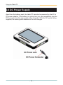
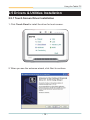
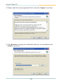
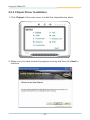
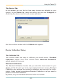
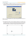
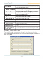
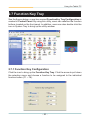
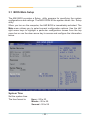
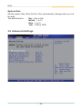
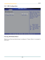
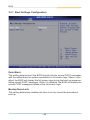
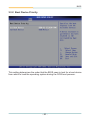
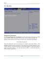
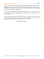
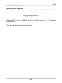
1
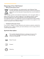
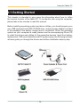
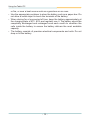
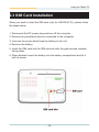
Gladius G0710(S)
Rugged Tablet PC
User's Manual
Version 1.0
P/N: 4012071000100P
2009.12
This page is intentionally left blank.
Index
Contents
Copyright Notice................................................................i
Declaration of Conformity.................................................i
Important Safety Instructions..........................................ii
Classification....................................................................iii
Disposing of Your Old Product.......................................iv
Symbols Description.......................................................iv
About User's Manual........................................................v
Warning..............................................................................v
Additional Information & Technical Support..................v
Contact Information..........................................................v
Warranty............................................................................vi
Chapter 1 - General Information..........................................1
1.1 Packing List.................................................................2
1.2 Ordering Information..................................................2
1.3 Specifications..............................................................3
1.4 Dimensions..................................................................5
1.5 Introduction.................................................................6
1.5.1 Front Side.........................................................7
1.5.2 Function Buttons.............................................8
1.5.3 LED Indicators.................................................8
1.5.4 Rear Side..........................................................9
1.5.5 Right Side.......................................................10
1.5.6 Left Side.........................................................10
Chapter 2 - Using the Tablet PC........................................11
2.1 Getting Started..........................................................12
2.2 Battery Replacement................................................13
2.3 SIM Card Installation................................................16
2.4 DC Power Supply......................................................17
2.5 Drivers & Utilities Installation..................................18
2.5.1 Touch Screen Driver Installation.................18
2.5.2 Chipset Driver Installation............................21
2.5.3 Graphics Driver Installation.........................24
--
Index
2.5.4 Audio Driver Installation...............................27
2.5.5 LAN Driver Installation..................................29
2.5.6 Wireless LAN Driver Installation..................31
2.5.7 Bluetooth Driver Installation........................32
2.5.8 RFID Driver Installation.................................36
2.5.9 Function Key Tray Installation.....................39
2.6 Touch Screen............................................................41
2.6.1 Tips for Using the Stylus..............................41
2.6.2 PenMount Monitor.........................................42
2.6.3 PenMount Control Panel...............................43
2.7 Function Key Tray.....................................................50
2.7.1 Function Key Configuration.........................50
Chapter 3 - BIOS.................................................................51
3.1 BIOS Main Setup......................................................52
3.2 Advanced Settings...................................................53
3.2.1
3.2.2
3.2.3
3.2.4
3.2.5
3.2.6
3.2.7
IDE Configuration................................................54
Brightness Default Level.....................................57
Install OS Configuration......................................57
Bluetooth Configuration.....................................57
RFID Configuration..............................................57
WiFi Configuration...............................................57
Battery Low Beep Configuration........................57
3.3 Boot Settings............................................................58
3.3.1 Boot Settings Configuration...............................59
3.3.2 Boot Device Priority............................................60
3.3 Security.....................................................................61
3.4 Exit Options..............................................................63
Appendix.............................................................................65
A.1 POGO Connector.....................................................66
- II -
Copyright Notice
All Rights Reserved.
The information in this document is subject to change without prior notice in
order to improve the reliability, design and function. It does not represent a
commitment on the part of the manufacturer.
Under no circumstances will the manufacturer be liable for any direct, indirect,
special, incidental, or consequential damages arising from the use or inability
to use the product or documentation, even if advised of the possibility of such
damages.
This document contains proprietary information protected by copyright.
All rights are reserved. No part of this manual may be reproduced by any
mechanical, electronic, or other means in any form without prior written
permission of the manufacturer.
Declaration of Conformity
CE Class B
This product has passed the CE test for environmental specifications when
shielded cables are used for external wiring. We recommend the use of
shielded cables. This kind of cable is available from ARBOR. Please contact
your local supplier for ordering information.
This product has passed the CE test for environmental specifications. Test
conditions for passing included the equipment being operated within an
industrial enclosure. In order to protect the product from being damaged by
ESD (Electrostatic Discharge) and EMI leakage, we strongly recommend the
use of CE-compliant industrial enclosure products.
FCC Class B
This device complies with part 15 of the FCC Rules. Operation is subject to
the following two conditions: (1) This device may not cause harmful interference, and (2) this device must accept any interference received, including
interference that may cause undesired operation.
This equipment has been tested and found to comply with the limits for a
Class B digital device, pursuant to part 15 of the FCC Rules. These limits
are designed to provide reasonable protection against harmful interference
when the equipment is operated in a residential environment. This equipment
generates, uses, and can radiate radio frequency energy and, if not installed
and used in accordance with the instructions, may cause harmful interference
to radio communications. Operation of this equipment in a residential area is
likely to cause harmful interference in which case the user will be required to
correct the interference at his own expense.
--
IEC 60601-1/EN60601-1
This product complies with the system standard IEC 60601-1 Medical Electrical Equipment Part 1: General Requirements for Safety. And therefore, the
product is exclusively interconnected with IEC 60601-1 certified equipment in
the patient environment.
Equipment connected to the analog or digital interfaces of the unit must comply
with the respective IEC standards (e.g. IEC 60601-1 for medical equipment).
Furthermore all configurations shall comply with the current version of the
standard for SYSTEMS IEC 60601-1-1. Everybody who connects additional
equipment to the signal input part or signal output part configures a medical
system, and is therefore responsible that the system complies with current
version of the requirements of the system standard IEC 60601-1-1. If in doubt,
consult the technical service department or your local representative.
Important Safety Instructions
Read these safety instructions carefully
1. Read all cautions and warnings on the equipment.
2. Place this equipment on a reliable surface when installing. Dropping it or
letting it fall may cause damage
3. Make sure the correct voltage is connected to the equipment.
4. For pluggable equipment, the socket outlet should be near the equipment
and should be easily accessible.
5. Keep this equipment away from humidity.
6. Disconnect this equipment from the A/C outlet before cleaning it. Use a moist
cloth. Do not use liquid or sprayed detergent for cleaning.
7. Do not scratch or rub the screen with a hard object.
8. Never use any of the solvents, such as Thinner Spray-type cleaner, Wax,
Benzene, Abrasive cleaner, Acid or Alkaline solvent, on the Medical Display.
Harsh chemicals may cause damage to the cabinet and the touch sensor.
9. Remove dirt with a lightly mositened cloth and a mild solvent detergent.
Then wipe the cabinet with a soft dry cloth.
7. The openings on the enclosure are for air convection and protect the equipment
from overheating. DO NOT COVER THE OPENINGS.
8. Position the power cord so that people cannot step on it. Do not place
anything over the power cord.
9. If the equipment will not be used for a long time, disconnect it from the power
source to avoid damage by transient overvoltage.
- ii -
10. Never pour any liquid into openings. This may cause fire or electrical
shock.
11. Never open the equipment. For safety reasons, the equipment should be
opened only by qualified service personnel.
12. If one of the following situations arises, get the equipment checked by
service personnel:
a. The power cord or plug is damaged.
b. Liquid has penetrated into the equipment.
c. The equipment has been exposed to moisture.
d. The equipment does not work well, or you cannot get it to work according
to the user's manual.
e. The equipment has been dropped or damaged.
f. The equipment has obvious signs of breakage.
13. The sound pressure level at the operator's position, according to
IEC 704-1:1982, is no more than 70dB(A).
14. Keep this User’s Manual for later reference.
15. DO NOT LEAVE THIS EQUIPMENT IN AN UNCONTROLLED
ENVIRONMENT WHERE THE STORAGE TEMPERATURE IS BELOW
-20° C (-4° F) OR ABOVE 60° C (140° F). THIS MAY DAMAGE THE
EQUIPMENT.
UL Class I Classfication: With respect to electric shock, fire and
mechanical hazards only, in accordance with UL-60601-1 and
CAN/CSA C22.2 No. 601.1.
Classification
•
Powered by Class I power supply
•
No applied part
•
Degree of protection against the ingress of water: IPX0
•
Mode of operation: Continuous
•
The equipment is not suitable for use in the presence of a flammable
anesthetic mixture with air or nitrous oxide: Not AP or APG Category.
- iii -
Disposing of Your Old Product
•
Within the European Union
EU-wide legislation, as implemented in each Member State,
requires that waste electrical and electronic products carrying the
mark (left) must be disposed of separately from normal household
waste.
This includes monitors and electrical accessories, such as signal cables or
power cords. When you need to dispose of your display products, please
follow the guidance of your local authority, or ask the shop where you
purchased the product, or if applicable, follow any agreements made between
yourself. The mark on electrical and electronic products only applies to the
current European Union Member States.
•
Outside the European Union
If you wish to dispose of used electrical and electronic products outside the
European Union, please contact your local authority so as to comply with the
correct disposal method.
Symbols Description
This symbol indicates that there is a danger of injury to the
user or a risk of damage to the product, should warning
notices be disregarded.
Direct Current
Ground
Stand-by
- iv -
About User's Manual
This User's Manual is intended for experienced users and integrators with
hardware knowledge of personal computers. If you are not sure about any
description in this User’s Manual, please consult your vendor before further
handling.
Warning
Any changes or modifications not expressly approved by the guarantee of this
device could void the user’s authority to operate the equipment.
Additional Information & Technical Support
You can download the related technical documents such as datasheet and
user’s manual as well as driver on our website.
Please do not hesitate to call or e-mail our customer service when you still
cannot get the information you need.
http://www.arbor.com.tw
E-mail: [email protected]
Contact Information
ARBOR Technology Corp.
10th fl., No. 700, Zhong Zheng Rd., Zhong He, 235 Taipei, Taiwan.
TEL: +886-2-8226-9396
FAX: +886-2-8226-9398
--
Warranty
This product is warranted to be in good working order for a period of one year
from the date of purchase. Should this product fail to be in good working order
at any time during this period, we will, at our option, replace or repair it at no
additional charge except as set forth in the following terms. This warranty
does not apply to products damaged by misuse, modifications, accident or
disaster. Please be advised that disassembling this equipment may void the
warranty as well.
Vendor assumes no liability for any damages, lost profits, lost savings or any
other incidental or consequential damage resulting from the use, misuse of,
or inability to use this product. Vendor will not be liable for any claim made by
any other related party.
Vendor disclaims all other warranties, either expressed or implied, including but
not limited to implied warranties of merchantibility and fitness for a particular
purpose, with respect to the hardware, the accompanying product’s manual(s)
and written materials, and any accompanying hardware. This limited warranty
gives you specific legal rights.
Return authorization must be obtained from the vendor before returned
merchandise will be accepted. Authorization can be obtained by calling or
faxing the vendor and requesting a Return Merchandise Authorization (RMA)
number. Returned goods should always be accompanied by a clear problem
description.
- vi -
General Information
1
Chapter 1
General Information
Chapter 1 - General Information
--
General Information
1.1 Packing List
Tablet PC
1 x Gladius G0710(S) Rugged Tablet PC
Accessories
1 x AC to DC Power Adapter
1 x Power Cord
1 x User’s Manual
1 x Driver CD
1 x Stylus
1 x Stylus-Pen Rope
Before up and running, please make sure the package contains all of above
accessories.
If any of the above items is damaged or missing, contact your vendor
immediately.
1.2 Ordering Information
G0710-CF
7" Intel Atom™ tablet PC with 4GB CF
G0710-HDD
7" Intel Atom™ tablet PC with 60GB 1.8" IDE HDD
G0710S-CF
7" Intel Atom™ tablet PC with 4GB CF, outdoor readable
touch screen
G0710S-HDD
7" Intel Atom™ tablet PC with 60GB 1.8" IDE HDD,
outdoor readable touch screen
PAC-M090W
90W AC/DC medical grade adapter and power cord kit
BAT-0710
Battery pack kit
HSUPA-0710
MiniCard HSUPA (3.75G) module supporting WCDMA,
HSUPA, HSDPA & E-GPRS, Triband HSDPA/UMTS (850,
1900 and 2100MHz), Quadband EDGE/GPRS/GSM (850,
900, 1800, and 1900MHz)
--
General Information
1.3 Specifications
Model Name
Gladius G0710(S) Rugged Tablet PC
CPU
Intel Atom Z510 1.1GHz with 400MHz FSB
Chipset
Intel® System Controller Hub US15W
Graphics Controller
GMA 500 Integrated
Memory
Soldered onboard 1GB DDR2-533 SDRAM
Audio
Azalia HD Audio codec ALC888-GR
1 x 4GB CompactFlash (default)
Storage
1 x 60GB 1.8" slim IDE HDD (option)
System
Realtek 8111B PCI-E Gigabit Ethernet
802.11 b/g/n WLAN
Connectivity
Bluetooth 2.0 + EDR module
RFID
Camera
I/O
HSUPA (3.75G) (optional)
ISO 15693/14443A/14443B RFID
(distance: 3 ~ 5cm; speed: 5 cards/sec.)
1 x 1.3 megapixel CMOS camera
w/ Microphone (front)
1 x 2.0 megapixel CMOS camera (rear)
Serial Port
1 x RS-232
USB Port
2 x USB 2.0
LAN
1 x RJ-45 GbE LAN
Power Input
1 x DC jack
Docking Connection 1 x 35-pin pogo connector for docking station
LEDs &
Buttons
LED Indicator
5 LEDs on the front panel
Power Button
1 x Power on/off button
Reset Button
1 x System reset button
RFID Button
1 x RFID on/off button
Function Button
8 x Function button
--
General Information
LCD Display
Touch Panel
Display
7” wide active matrix TFT
Resolution
1024 x 600 resistive touch panel
Brightness
375 cd/m2 (typ.)
Contrast
400:1
Backlight Type
LED
Panel Type
Resistive
Transparency
73% (typ.)
Power Input: 100 ~ 240VAC
Power
System
Power Adapter
Battery
Power Output: 20VDC, 90W (G0710)
20VDC, 60W (G0710S)
Li-ion battery pack 4S1P 2600mAH;
Approximately 4hrs charged battery life
210 x 36 x 160 mm
(8.26" x 1.42" x 6.29")
Dimensions
(W x D x H)
0 ~ 45ºC (32 ~ 113ºF)
Operating Temp.
Transport & Storage
-20 ~ 60ºC (-4 ~ 140ºF)
Temp.
Operating Humidity 5 ~ 85% (non-condensing)
Mechanical &
Environmental
Storage Humidity
5 ~ 95% (non-condensing)
EMI/EMC
CE/FCC Class B, UL60601-1, EN60601-1/
EN60601-1-2 compliant
IP Rating
Front panel, IP54 compliant
Vibration
1 Grms/5 ~ 500Hz/random operation
Shock
10G acceleration (peak; 11ms duration)
Transit Drop
1.2m (4ft) drop on wood
(five sides except the front side)
Weight (Net)
1kg (2.2 lb)
--
General Information
1.4 Dimensions
210
160
36
Unit: mm
--
General Information
1.5 Introduction
As an ultra slim and ultra light unit which is easily to access, the tablet PC is
equipped with a 7” active matrix TFT panel with a touch screen in front of it. The
enclosure of the unit is IP54 compliant; and designed with the Intel Atom Z510
processor that consumes ultra low power, the system using passive ventilation
does not rely on fans which are often unreliable. Besides, the system features
instant resume and long charged battery life up to four hours.
35-pin POGO connector
to docking station
--
General Information
1.5.1 Front Side
Battery LED
HDD LED
Bluetooth LED
RFID LED
Power LED
Microphone
CMOS Camera
Speaker
Function Buttons
Note:
The eight function buttons (F1 ~ F8) on the front panel are available after
users have installed the Function Key utility. These buttons can be defined
by users. The Control Buttons table below lists the default value for each
function button. Should you want to change the settings, please select Start
> Settings > Control Panel and then click the Function Key Configure icon
to configure the functions of those buttons.
--
General Information
1.5.2 Function Buttons
Button
Description
Brightness Up
Press to increase brightness
Brightness Down Press to decrease brightness
Volume Up
Press to increase speaker volume
Volume Down
Press to decrease speaker volume
Mute
Press to enable/disable sound
Bluetooth
Press to enable/disable Bluetooth connectivity
Wi-Fi
Press to enable/disable Wi-Fi connectivity
Touch
Press to lock/unlock the touch screen.
1.5.3 LED Indicators
LED
Color
Power
Green
RFID
Amber
Status
Description
On
Power on
Off
No power
On
RFID reader enabled
Off
RFID reader disabled
Bluetooth Blue
Blinking
Bluetooth connection is active
HDD
Purple
Blinking
HDD is accessing
On
Battery fully charged
Battery
Green
Blinking
Battery is charging
--
General Information
1.5.4 Rear Side
CMOS Camera
Stylus
Battery
Note:
There are two CCD camera located on the front and rear panels respectively.
Only one CCD camera functions at a time.
--
General Information
1.5.5 Right Side
Reset button
Rubber cover
attachment
USB port
RJ-45 LAN port
DC power jack
Power button
1.5.6 Left Side
RFID button
Rubber cover
attachment
RS-232 port
USB port
- 10 -
Using the Tablet PC
2
Chapter 2
Using the Tablet PC
Chapter 2 - Using the Tablet PC
- 11 -
Using the Tablet PC
2.1 Getting Started
This chapter is intended to give users the information about how to utilize
the various function of the tablet PC. To be familiar with using the computer,
please take a few minutes to read this manual.
Before installing operating system and driver utilities, you should prepare your
own USB keyboard and USB CD ROM drive, and the power adapter included
in the package if the battery charge level is insufficient. When the operating
system on your computer is ready, please use the accompanying Driver CD
to install the drivers and utilities for the respective devices. Apart from battery
replacement, SIM card installation and DC power supply, the following sections
will also guide you through the drivers and utilities installation step by step.
- 12 -
Using the Tablet PC
2.2 Battery Replacement
The tablet PC is equipped with a 4S1P rechargeable battery pack. When you
want to replace the battery or remove it for SIM card installation, please follow
the steps below:
1. Disconnect the DC power plug and turn off the computer.
2. Remove any peripheral devices connected to the computer.
3. Unscrew the screw which fixes the battery to the unit.
4. Remove the battery.
5. Insert the new battery into the battery compartment and fix it with the
screw.
Battery pack
Battery compartment
- 13 -
Using the Tablet PC
Instructions for Rechargeable Battery Pack
How to recharge:
• To recharge the Lithium-ion battery pack, install it into the computer and
then connect the power adapter to the power input plug of the computer.
• The battery will be fully charged within 2-4 hours (depending on the capacity
of the battery). When finished charging, the charge indicator will turn on
steadily in green and then it’s recommended to remove the adapter from
the computer.
•It’s recommended not to recharge intermittently, which means not plugging
and unplugging the power adapter frequently in short period of time.
•It’s recommended to turn off the computer before charging.
• Do not use the power adapter that is not made for your computer. Supplying
the computer with inappropriate voltage may cause harm to the battery or,
even worse, may burn the computer.
How to use:
•It’s recommended to supply power via the adapter without the battery
installed, while you are to use the computer for a long time. And reinstall
the battery before you go out.
• The lithium-ion battery is currently one of the most popular battery packs
right now. The biggest advantage is that it has no memory effect that users
needn’t worry about. Users can charge the battery anytime whether the
battery is fully drained or not. However, it’s recommended that users drain the
battery until the system shows power shortage warning and then recharge
the battery. Doing so is helpful to the reliability of using the battery.
• Don’t use the battery pack as a power supply for other equipment.
How to store:
• Don’t expose the battery to elevated heat situations such as under direct
sunlight in a car or near fire.
• Don’t disassemble the battery, or the battery leakage might cause skin or
eye injury. If electrolyte leaking from the battery pack contacts your skin
or clothing, immediately flush it with running water. If it splashes in eye,
rinse the eye at least 15 minutes with clean water and then seek medical
attention.
• To avoid battery leakage or explosion, don’t discard the battery into water
- 14 -
Using the Tablet PC
or fire, or near a heat source such as a gas stove or an oven.
• Use the appropriate container to store the battery such as a paper box. Do
not allow a metal object to touch the terminals of the battery.
• When storing for a long period of time, keep the battery approximately at
the charging state of 60 ~ 80% and regularly use it. The battery should be
completely discharged and recharged once each month to condition the
cells inside the battery to ensure the battery delivers the most available
capacity.
• The battery consists of precision electrical components and cells. Do not
drop or hit the battery.
- 15 -
Using the Tablet PC
2.3 SIM Card Installation
When you want to insert the SIM card (only for HSUPA-0710), please follow
the steps below:
1. Disconnect the DC power plug and turn off the computer.
2. Remove any peripheral devices connected to the computer.
3. Unscrew the screw which fixes the battery to the unit.
4. Remove the battery.
5. Insert the SIM card into the SIM card slot with the gold-colored contacts
facing down.
6. When finished, insert the battery into the battery compartment and fix it
with its screw.
- 16 -
Using the Tablet PC
2.4 DC Power Supply
Apart from the battery pack, the table PC can also be powered by the AC to
DC power adpater. If the battery is running low, you can immediately plug the
DC connector into the power jack of the computer. With the DC power being
supplied, the battery pack attached to the unit charges.
- 17 -
Using the Tablet PC
2.5 Drivers & Utilities Installation
2.5.1 Touch Screen Driver Installation
1. Click Touch Panel to install the driver for touch screen.
2. When you see the welcome wizard, click Next to continue.
- 18 -
Using the Tablet PC
3. Please read the license agreement first, and click I Agree to continue.
4. Click Browse to change the installation directory, or immediately click
Install to continue.
- 19 -
Using the Tablet PC
5. Please wait for a while until the progress bar completes.
6. The installation is completed. Click Finish to close this window.
- 20 -
Using the Tablet PC
2.5.2 Chipset Driver Installation
1. Click Chipset of the main menu to install the chipset device driver.
2. Make sure you have closed all programs running and then click Next to
continue.
- 21 -
Using the Tablet PC
3. Please read the license agreement first, and click Yes to continue.
4. Please read the License Aggrement by pulling down the scroll bar, and
click Next to continue.
- 22 -
Using the Tablet PC
5. The chipset device driver installation is completed. Click Finish to close
the window.
- 23 -
Using the Tablet PC
2.5.3 Graphics Driver Installation
1. Click VGA of the main menu to install the graphics device driver.
2. Make sure you have closed all programs running and then click Next to
continue.
- 24 -
Using the Tablet PC
3. Please read the license agreement first, and click Yes to continue.
4. Please read the Readme file for system requiremsnts and installation
information, and click Next to continue.
- 25 -
Using the Tablet PC
5. The graphics device driver installation is completed. Click Next to
continue.
6. After installing the graphics device driver, click Finish with Yes radio button
selected to restart your computer to have the changes take effect, or with
No to restart this computer later.
- 26 -
Using the Tablet PC
2.5.4 Audio Driver Installation
1. Click Audio of the main menu to install the audio device driver.
2. Click Next to continue.
- 27 -
Using the Tablet PC
3. After installing the audio device driver, click Finish with Yes radio button
selected to restart your computer to have the changes take effect, or with
No to restart this computer later.
- 28 -
Using the Tablet PC
2.5.5 LAN Driver Installation
1. Click LAN of the main menu to install the LAN device driver.
2. Click Next to continue.
- 29 -
Using the Tablet PC
3. Click Install to start installation, or Back to go back to the previous step.
4. Click Finish to close the wizard window.
- 30 -
Using the Tablet PC
2.5.6 Wireless LAN Driver Installation
1. Click Wireless LAN of the main menu to install the wireless LAN device
driver.
2. The installation is in progress; when the progress bar reaches the end, the
installation is completed.
- 31 -
Using the Tablet PC
2.5.7 Bluetooth Driver Installation
1. Click Bluetooth of the main menu to install the Bluetooth device driver.
2. A dialog box shows up. Click the down arrow to drop down the selection
menu and choose a language item and then click OK to continue.
- 32 -
Using the Tablet PC
3. Check the driver information and click Next to continue.
4. Please read the license agreement first; select I accept the terms in the
license agreement and then click Next to continue.
- 33 -
Using the Tablet PC
5. If you want to create shortcuts to Startup folder or Desktop, tick the check
boxes beside the text label and then click Next to continue.
6. Click Next to install to this folder, or click Change to install to a different
folder.
- 34 -
Using the Tablet PC
7. Click Install to start installation, or click Back to go back to the previous
step.
8. After the installation is completed, click Finish to close the window.
- 35 -
Using the Tablet PC
2.5.8 RFID Driver Installation
1. Click RFID of the main menu to install the RFID and USB devices driver.
2. Read the driver information and then click Next to continue.
- 36 -
Using the Tablet PC
3. Click Next to install to this folder, or click Browse to install to a different
folder.
4. The driver is being installed, please wait for a while.
- 37 -
Using the Tablet PC
5. Click Finish to complete the installation.
Note:
After installation, the RFID device information in Device Manager may
appear with an exclamation mark. To solve this problem, please manually
update the driver for this device, just once.
- 38 -
Using the Tablet PC
2.5.9 Function Key Tray Installation
1. After you put the CD-ROM into the CD-ROM drive, the driver and utility
installation main menu appears. Click FunctionKey to install the function
key configuration utility.
2. Click Next to continue.
- 39 -
Using the Tablet PC
3. When the installation is completed, click Finish to close the window.
- 40 -
Using the Tablet PC
2.6 Touch Screen
2.6.1 Tips for Using the Stylus
With the touch screen driver installed, users can use the stylus like a computer
mouse to control the computer. Tapping with the stylus is equivalent to clicking
with the left button of a mouse. For the right button behavior, tap anywhere on
the screen and hold down until the menu is shown.
Also, users can have the mouse icon showing on the right side of the screen
(see the next section—PenMount Monitor).
Tap the mouse icon to switch between Right and Left button functions, which
means the stylus touching the screen will behave the same as clicking the
Right/Left mouse button.
- 41 -
Using the Tablet PC
2.6.2 PenMount Monitor
The PenMount Monitor icon (PM) appears in the system tray at the bottomright corner when you turn on PenMount Monitor in PenMount Utilities.
Tap on the PM icon and hold down for the pop-up menu shown below.
PenMount Monitor has the following functions:
Control Panel
Launch the PenMount Control Panel utility.
Beep
Set the Beep function for each device.
Right Button
After ticking this item, a mouse icon
right side of the screen.
Exit
Exits the PenMount Monitor function.
- 42 -
appears on the
Using the Tablet PC
2.6.3 PenMount Control Panel
After you have selected the Control Panel item on the pop-up menu, the
PenMount Control Panel utility UI appears as below. The functions of the
PenMount Control Panel such as Device, Calibrate, Setting, Multiple
Monitors, Tools and About are explained in the following sections.
The Tools Tab
When you click the PenMount icon in the system tray and select "Control
Panel" from the menu, "PenMount Control Panel" will appear. Among the
four tabs—Device, Multiple Monitors, Tools and About—the function of Tools
should be described first as follows:
Draw
Tests or demonstrates the PenMount touch screen operation.
Advanced Calibration
Enable Advanced Calibration function.
Right Button Icon
Enable right button function. The icon can show on Desktop or in the system
tray at the bottom-right corner.
- 43 -
Using the Tablet PC
The Device Tab
In this window, you can find out how many devices are detected on your
system. On the Device tab, select the device icon and tap Configure, or
double tap the device icon for touch screen calibration.
And then another window with the Calibrate tab appears.
Device Calibration Dialog
The Calibrate Tab
This function offers two ways to calibrate your touch screen. ‘Standard
Calibration‘ adjusts most touch screens while ‘Advanced Calibration’
adjusts aging touch screens.
Standard Calibration
The Standard Calibration function lets you match the touch screen to your
display so that the point you touch is accurately tracked on screen. Standard
Calibration only requires four points for calibration and one point for confirmation. Under normal circumstance Standard Calibration is all you need to
perform an accurate calibration.
By default, only the Standard Calibration button is available.
- 44 -
Using the Tablet PC
1. Please tap the Standard Calibration button to start calibration procedures.
2. After tapping the button, the arrow appears pointing to a red square.
Use your finger or stylus to touch the red square and hold down until the
screen shows the message—"Lift off to proceed".
3. And then the next arrow appears. After the fifth red point calibration is
complete, press ESC key to quit.
- 45 -
Using the Tablet PC
NOTE:
The older the touch screen gets, the more Advanced Mode calibration points
you need for an accurate calibration. Use a stylus during Advanced Calibration for greater accuracy. Please follow the step as below:
Advanced Calibration
The Advanced Calibration function improves the accuracy of calibration by
using more involved engineering calculations. Use this function only if you
have tried the Standard Calibration and there is still a discrepancy in the
way the touch screen maps to the display. You can choose 4, 9, 16 or 25
points to calibrate, though we suggest that you first try 9 points, if it is still not
tracking well then try 16 or 25 points. The more points you use for calibration, the greater the accuracy. Errors in calibration may occur due to viewing angle, or individual skill, and there may be little difference in using 16 or
25 points. Note that a stylus is recommended for the most accurate results.
1. Come back to PenMount Control Panel and select the Tools tab. Tap the
Advanced Calibration button to enable it (when enabled, the small
rectangle in the middle appears in yellow).
- 46 -
Using the Tablet PC
2. Select Device to calibrate, and then you can start to do "Advanced
Calibration". Tap the arrow to pull down the drop-down menu and select the
number determining how many points will be used for calibration.
Note: You are recommended to use a stylus during Advanced Calibration for
greater accuracy.
3. After tapping the button, the arrow appears pointing to a red square. Use
your finger or stylus to touch the red square and hold down until the screen
shows the message—"Lift off to proceed" and then the next arrow appears.
After the fifth red point calibration is complete, press ESC key to quit.
- 47 -
Using the Tablet PC
Plot Calibration Data
Check this function to have touch panel linearity comparison graph appear
when you finish Advanced Calibration. The black lines reflect the ideal linearity assumed by PenMount's application program while the blue lines show
the approximate linearity calculated by PenMount's application program as
the result of user’s execution of Advance Calibration.
Turn off EEPROM storage
Tick this function to disable the write-in of calibration data in Controller.
The Setting Tab
- 48 -
Using the Tablet PC
Touch Mode
This mode enables and disables the mouse's ability to drag on-screen icons.
Mouse Emulation
Select this mode and the mouse functions as
normal and allows dragging of icons.
Click on Touch
Select this mode and the mouse only provides a
click function, and dragging is disabled.
Beep Sound
Turn On/Off Beep Sound.
Beep on Pen
Down
Beep occurs when pen is down.
Beep on Pen Up
Beep occurs when pen is up.
Beep on Both
Beep occurs when pen is down or up.
Beep Frequency
Modifies sound frequency.
Beep Duration
Modifies sound duration.
Cursor Stabilizer
Enable the function supporting to prevent cursor
shake.
Use press and hold
as right click
You can set the time out and area as you need.
The Edge Compensation Tab
This tab is the edge compensation settings for the advanced calibration.
You can adjust the settings from 0 to 30 for accommodating the difference of
each touch panel.
- 49 -
Using the Tablet PC
2.7 Function Key Tray
See the figures below, a new item named FunctionKey Tray Configuration is
created in Control Panel. By using this utility, users can redefine the function
buttons located on the front panel. In addition, users can also double click the
icon in System Tray to bring up the utility window.
2.7.1 Function Key Configuration
Click the icon to bring up the Function Key Tray. Click the arrow to pull down
the selection menu and choose a function to be assigned to the individual
function button (F1 ~ F8).
- 50 -
BIOS
3
Chapter 3
BIOS
Chapter 3 - BIOS
- 51 -
BIOS
3.1 BIOS Main Setup
The AMI BIOS provides a Setup utility program for specifying the system
configurations and settings. The BIOS ROM of the system stores the Setup
utility.
When you turn on the computer, the AMI BIOS is immediately activated. The
Main menu allows you to select several configuration options. Use the left/
right arrow keys to highlight a particular configuration screen from the top
menu bar or use the down arrow key to access and configure the information
below.
System Time
Set the system time.
The time format is:
Hour : 00 to 23
Minute : 00 to 59
Second : 00 to 59
- 52 -
BIOS
System Date
Set the system date. Note that the ‘Day’ automatically changes when you set
the date.
The date format is:
Day : Sun to Sat
Month : 1 to 12
Date : 1 to 31
Year : 1999 to 2099
3.2 Advanced Settings
- 53 -
BIOS
3.2.1 IDE Configuration
Primary IDE Master/Slave
Select one of the hard disk drives to configure it. Press <Enter> to access its
sub menu.
- 54 -
BIOS
IDE Configuration Sub Menu
Type
This setting determines the type of the IDE device. The default value is
Auto.
LBA/Large Mode
This setting enables or disables support for IDE drives with capacities greater
than 528MB. The default value is Auto.
Block (Multi-Sector Transfer)
This setting enables or disables to support IDE drives using Block Mode. The
default value is Auto.
PIO Mode
This setting determines the IDE Programmed I/O mode. The default value is
Auto.
- 55 -
BIOS
DMA Mode
This setting determines the IDE DMA mode. The default value is Auto.
S.M.A.R.T
This setting determines the IDE Self-Monitoring, Analysis and Reporting
Technology mode. The default value is Auto.
32Bit Data Transfer
This setting determines support for IDE drives that permit 32-bit accesses.
The default value is Enabled.
- 56 -
BIOS
3.2.2 Brightness Default Level
This setting determines the default brightness level ranging from 0 to 7. By
default, the value is set to 5.
3.2.3 Install OS Configuration
Use this setting to enable/disable the OS installing configuration.
3.2.4 Bluetooth Configuration
Use this setting to enable/disable the Bluetooth function.
3.2.5 RFID Configuration
Use this setting to enable/disable the RFID function.
3.2.6 WiFi Configuration
Use this setting to enable/disable the WiFi function.
3.2.7 Battery Low Beep Configuration
Use this setting to enable/disable the beep when battery is running low.
- 57 -
BIOS
3.3 Boot Settings
- 58 -
BIOS
3.3.1 Boot Settings Configuration
Quiet Boot
This setting determines if the BIOS should hide the normal POST messages
with the motherboard or system manufacture’s full-screen logo. When it is enabled, the BIOS will diaplay the full-screen logo during the boot-up sequence,
hiding normal POST messages. When it is disabled, the BIOS will display the
normal POST messages instead of the full-screen logo.
Bootup Num-Lock
This setting determines whether the Num Lock key should be activated at
boot up.
- 59 -
BIOS
3.3.2 Boot Device Priority
This setting determines the order that the BIOS uses to look for a boot device
from which to load the operating system during the DOS boot process.
- 60 -
BIOS
3.3 Security
Supervisor Password
Set Change Supervisor Password to enter and change the options of the
setup menus. When you select this function, the following message will
appear at the center of the screen to assist you in creating a password.
Enter New Password:
Type the password, up to six characters in length, and press <Enter>. The
password typed now will substitute for any previously entered password from
CMOS memory. You will be asked to confirm the password. Type the password
again and press <Enter>. You may also press <ESC> to abort the selection
and not enter a password.
- 61 -
BIOS
With a password enabled, a Password Check item appears. Set this item to
Setup, you will be prompted to enter the password every time you try to enter
the BIOS Setup utility. This prevents an unauthorized person from changing
any part of your system configuration.
You can also require the BIOS to request a password every time your system
is rebooted by setting it to Always. This would prevent unauthorized use of
your computer.
To clear a password, just leave the field blank and press <Enter> when you
are prompted to enter a new password. Once the password is cleared, the
following message will appear at the center of the screen.
Password Uninstalled.
- 62 -
BIOS
3.4 Exit Options
Save Changes and Exit
Pressing <Enter> on this item and it asks for confirmation:
Save configuration changes and exit setup?
Pressing <OK> stores the selection made in the menus in CMOS - a special
section of memory that stays on after you turn your system off. The next
time you boot your computer, the BIOS configures your system according to
the Setup selections stored in CMOS. After saving the values the system is
restarted again.
Discard Changes and Exit
Exit system setup without saving any changes.
<ESC> key can be used for this operation.
- 63 -
BIOS
Load Optimal Defaults
When you press <Enter> on this item, you get a confirmation dialog box with
a message:
Load Optimal Defaults?
[OK]
[Cancel]
Pressing [OK] loads the BIOS Optimal Default values for all the setup
configurations.
<F9> key can be used for this operation.
- 64 -
Appendix
Appendix
Appendix
- 65 -
Appendix
A.1 POGO Connector
G0710 is equipped with a POGO 35-pin connector. For further information
about this interface, please refer to the pin arrangement/assignments shown
below.
Pin Arrangement
Pin Assignments
Definition
Pin
Definition
Pin
1
GND
19
SYSTEM_IN#
2
GND
20
LAN_TRL3-
3
+20AUX
21
SMB_CLK_CPU
4
LAN_TRL0+
22
3V3SB
5
+20AUX
23
SMB_DATA_CPU
6
LAN_TRL0-
24
USB_PP2
7
+20AUX
25
CRT_R_HSYNC
8
LAN_TRL1+
26
USB_PN2
9
VCC5
27
CRT_R_VSYNC
10
LAN_TRL1-
28
CRADLE_IN#
11
VCC3
29
CRT_BLUE
12
GND
30
CRT_CLK
13
VCC5
31
CRT_GREEN
14
LAN_TRL2+
32
CRT_DAT
15
VCC5
33
CRT_RED
16
LAN_TRL2-
34
GND
17
DOCK_GPIO
35
GND
18
LAN_TRL3+
- 66 -