1
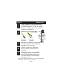
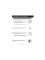
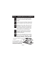
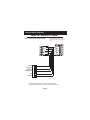
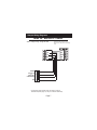
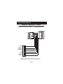
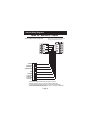
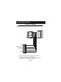
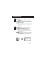
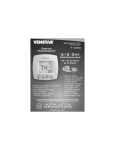
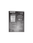
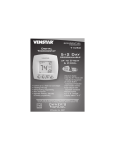
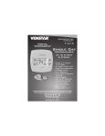
OWNER'S MANUAL
Digital 1 For
Thermostat
MODEL 33CS050/1-FS
COMMERCIAL
All T0051FS
HOTEL THERMOSTAT
Programmable
MULTI-STAGE
PROGRAMMABLE
PROGRAMMABLE
Digital Thermostat
up to 2-heat
& 2-cool
SmartTemp Equipped
Digital Temperature Selection
HEAT
HEATOnly
Can Display
Setpoint,
COOL
PUMP
r
e
AUTO
Warm
Thermoglow Backlight
ff
/O
On
r
Coole
Easy,
Pushbutton
WITH
48 Control
HOUR
Fan
‘Hidden’
Setpoint
Limiting
CLOCK
BACKUP
On/Off
Warmer
Auto-Changeover
MountsEquipped
Flush with the Wall
Dry Contact
Backlit
display
Fan
Peak Demand
Control up to 2 HeatCooler
& 2 Cool Stages
One For Reduction
All Works with
SmartTemp Equipped
Equipment
Manual Virtually
or AutoAll
Fan
Control
Digital Temperature Selection F or C Display
‘O’ or ‘B’ Terminal
74
Optional Setpoint - Only Display
Non-Volatile Memory
Easy Pushbutton
ControlSpecifically for the Lodging
‘Hidden’Industry
Setpoint Limiting
Designed
Auto-Changeover
Peak Demand Reduction
Dry Contact
Manual
or Auto
Control
Use with Equipped
most Air Conditioning & Heating Systems
including:
1 orFan
2 Stage
Electric
Cooling
Display
Either
F or&CGas Heating, Heat Pump, Electric or Hydronic Heat.
Designed
Specifically
the Lodging
Industry
Includes
Wall Hanger,forJ-Box
Not Required
Use with most Air Conditioning & Heating Systems including: 1 or 2 Stage
Electric Cooling & 2 Stage Gas Heating, Heat Pump, Electric or Hydronic Heat.
INSTALLATION
INSTRUCTIONS
Carrier Corporation 04/07
Venstar Inc. 12/07
4Z95
Table Of Contents
Step #1: Preparation
2
Step #2: Remove & Replace
Old Thermostat
4
Step #3: Wire Connections
5
Step #4: Test Operation
13
Troubleshooting
14
CAUTION
Follow Installation Instructions carefully.
DISCONNECT POWER TO THE HEATER AIR CONDITIONER BEFORE REMOVING
THE OLD THERMOSTAT AND INSTALLING
THE NEW THERMOSTAT.
WARNING
Venstar Inc. 12/07
P/N T0051FS
This device complies with Part 15 of the FCC rules.
Operation is subject to the following two conditions:
(1) This device may not cause harmful interference, and
(2) this device must accept any interference received,
including interference that may cause undesired operation.
Page 1
STEP #1
PREPARATION
WALL
Proper installation of the thermostat will be
accomplished by following these step
by step instructions. If you are unsure
about any of these steps, call a qualified
technician for assistance.
Assemble tools & recommended FLATSTAT
Junction Box*.
Flat Blade
Screwdriver
Wire cutter
& Stripper
.366”
Make sure your Heater/Air Conditioner
is working properly before beginning
installation of the thermostat.
FlatStat
in Small
J-Box
WALL
EXTENDS
LESS THAN
3/8” FROM
THE WALL.
Carefully unpack the thermostat.
Save the screws, wall anchors, and
instructions.
Turn off the power to the Heating/Air
Conditioning system at the main fuse
panel. Most residential systems have
a separate breaker for disconnecting
power to the furnace.
*‘Mud rings’ or Remodel boxes will not fit. The provided FlatStat
Wall Hanger may also be used. See page 3.
Page 2
INSTALLING FLATSTAT WALL HANGER
TM
Installation Instructions - FlatStat Wall Hanger
Mark the wall location using the inside opening of
the wall bracket as a template.
Make sure the rectangle is straight up and down
and there is nothing behind the planned opening
inside the wall before cutting.
Cut through the drywall just outside the outline.
Using your fingers, bend the steel tabs around
to the inside of the wall as shown.
Again, making sure the wall bracket is straight up
and down, secure the bracket to the wall with the
two phillips screws provided.
The screws will go through the wall and steel tabs,
‘clamping’ the wall hanger securely to the wall.
When ready to mount the FlatStat to the wall
hanger, use the two # 6 machine screws
provided.
Page 3
STEP #2
REMOVE & REPLACE OLD THERMOSTAT
Remove the cover of the old thermostat.
If it does not come off easily check for
screws.
Loosen the screws holding the thermostat
base or subbase to the wall, and lift away.
Disconnect the wires from the old
thermostat. Tape the ends of the wires
as you disconnect them, and mark them
with the letter of the terminal for easy
reconnection to the new thermostat.
Keep the old thermostat for reference
purposes, until your new thermostat is
functioning properly.
Remove the white plastic wire connector
from the rear of the thermostat. Install
wires as directed. Press the wired
connector on the back of the thermostat.
Lift Connector straight up
to remove.
For best operation, install
the thermostat in a junction
box that is free from drafts
that originate inside the wall.
Page 4
STEP #3
WIRE CONNECTIONS
If the terminal designations on your old
thermostat do not match those on the
new thermostat, refer to the chart below,
or the wiring diagrams that follow.
Wire from the
old thermostat
terminal marked
Function
G or F
Fan
Y1, Y or C
Cooling
W1, W or H
Heating
Install on the
new thermos tat
connector marked
G
Y1
W1,O,B
Rh, R, M, Vr, A
Power
C
Common
C*
R
O/b
Rev. Valve
W1,O,B**
Y2
2nd Stage Cool
Y2
W2
2nd Stage Heat
W2
RS+5
Remote Sensor +5vdc
RS+5
RS
Remote Sensor Signal
RS
RS G
Remote Sensor Ground
GND
* C may not be used on all systems.
** O/B is used if your system is a Heat Pump.
Page 5
Sample Wiring Diagrams
Gas or Electric Heat
5 Wire, 1 Stage Cooling, 1 Stage Gas Heat
W
FAN
G
COMPRESSOR
COMMON
C
GAS VALVE
or
STRIP HEAT
Y
POWER
CK1
GND
RS
RS+5
W2
Y2
R
C
G
Y1
W1-O-B
R
Residential Gas or Electric Heat*,
Electric Cool, split systems & package
units
* If using first stage electric heat, this option must be
selected ON (see page 15, step 13 of Owner’s Manual).
Page 6
Sample Wiring Diagrams
Gas or Electric Heat
4 Wire, 1 Stage Cooling, 1 Stage Gas Heat
GAS VALVE
or
STRIP HEAT
W
COMPRESSOR
Y
FAN
G
POWER
CK1
GND
RS
RS+5
W2
Y2
R
C
G
Y1
W1-O-B
R
Residential Gas or Electric Heat*,
Electric Cool, split systems & package
units
* If using first stage electric heat, this option must be
selected ON (see page 15, step 13 of Owner’s Manual).
Page 7
Sample Wiring Diagrams
Gas or Electric Heat
6 Wire, 2 Stage Cooling, 1 Stage Gas Heat
W
COMPRESSOR
COMMON
C
2nd STAGE
COOLING
Y2
FAN
G
GAS VALVE
or
STRIP HEAT
Y
POWER
CK1
GND
RS
RS+5
W2
Y2
R
C
G
Y1
W1-O-B
R
Residential two stage cooling with
Gas or Electric Heat*.
* If using first stage electric heat, this option must be
selected ON (see page 15, step 13 of Owner’s Manual).
Page 8
Sample Wiring Diagrams
Gas or Electric Heat
6 Wire, 1 Stage Cooling, 2 Stage Heat
Residential & commercial 1 Stage Cooling,
with 2 Stage Gas or Electric Heat*
W
COMPRESSOR
COMMON
C
2nd STAGE
HEATING
W2
FAN
G
GAS VALVE
or
STRIP HEAT
Y
POWER
CK1
GND
RS
RS+5
W2
Y2
R
C
G
Y1
W1-O-B
R
* If using first stage electric heat, this option must be
selected ON (see page 15, step 13 of Owner’s Manual).
Page 9
Sample Wiring Diagrams
Gas or Electric Heat
Commercial Gas or Electric Heat *,
Electric Cool, split systems & package units
including Commercial Heat Pumps **
7 Wire, 2 Stage Cooling, 2 Stage Heat
W
COMPRESSOR
COMMON
C
2nd STAGE
HEATING
2nd STAGE
COOLING
Y2 W2
FAN
G
GAS VALVE
or
STRIP HEAT
Y
POWER
CK1
GND
RS
RS+5
W2
Y2
R
C
G
Y1
W1-O-B
R
* If using first stage electric heat, this option must be
selected ON (see page 15, step 13 of Owner’s Manual).
** Commercial heat pumps do not have the heat pump turned
ON in advanced setup (see page 15, step 11 of Owner’s Manual).
Page 10
Sample Wiring Diagrams
Heat Pump
5 Wire, 1 Stage Cooling, 1 Stage Heat-Heat Pump* with O or b reversing valve**.
Residential Heat Pumps, split systems & package units, with no auxiliary heat.
O/b
FAN
G
COMPRESSOR
COMMON
C
REVERSING VALVE**
Y
POWER
CK1
GND
RS
RS+5
W2
Y2
R
C
G
Y1
W1-O-B
R
* This option must be selected ON during advanced setup
(see page 15, step 11 of Owner’s Manual).
** This option must be selected O or b during advanced setup
(see page 15, step 12 of Owner’s Manual).
Page 11
Sample Wiring Diagrams
Heat Pump
6 Wire, 1 Stage Cooling, 2 Stage Heat-Heat Pump* with O or b reversing valve**.
Residential Heat Pumps, split systems & package units, with auxiliary heat.
O/b
COMPRESSOR
COMMON
C
2nd STAGE
HEATING
W2
FAN
G
REVERSING VALVE**
Y
POWER
CK1
GND
RS
RS+5
W2
Y2
R
C
G
Y1
W1-O-B
R
* This option must be selected ON during advanced setup
(see page 15, step 11 of Owner’s Manual).
** This option must be selected O or b during advanced setup
(see page 15, step 12 of Owner’s Manual).
Page 12
STEP #4
TEST OPERATION
Turn the power on to the Heating/Air
Conditioning system.
Press the MODE button repeatedly until
the HEAT icon appears on the display.
Press the UP or DOWN buttons until the set
temperature is 10 degrees above room
temperature.
The HVAC unit should
energize in the heating mode.
Press the MODE button repeatedly until
the COOL icon appears on the display.
Press the UP or DOWN buttons until the set
temperature is 10 degrees below room
temperature.
The HVAC unit should
energize in the cooling mode.
NOTE: Most equipment has a time delay
of 5 minutes between cool cycles. This
feature is defeatable on the thermostat
(see page 16, step 17 of Owner's Manual).
Press the UP button until the setpoint is
equal to the room temperature. Press the
FAN button to Fan On. The fan should turn
on and run continuously.
Page 13
TROUBLESHOOTING
SYMPTOM: When using 4 wires (R, G, W, Y),
the air conditioning equipment tries
repeatedly to turn on, but cannot. At
times the display dims or disappears.
CAUSE: There is not enough power available
to "power share".
REMEDY: Connect a 250 ohm, 10 watt power
resistor at the furnace as shown below.
R
G
W
Y
C
TR300-10w
SYMPTOM: The air conditioning does not
attempt to turn on.
CAUSE: The compressor timer lockout may
prevent the air conditioner from
turning on, for a period of time.
REMEDY: See page 16 of the Owner's Manual
and configure step 17 to defeat the 5minute compressor lockout.
SYMPTOM: The display is blank.
CAUSE: Lack of proper power.
REMEDY: Make sure power is turned on to
the furnace and 24vac between R & W.
If C is used, 24vac between R & C.
Page 14
TROUBLESHOOTING
SYMPTOM: When controlling a residential heat
pump, and asking for cooling, the heat
comes on.
CAUSE: Heat pump is not selected "ON" in the
Advanced Setup.
REMEDY: See page 15 of the Owner's Manual
and configure step 11 to enable heat pump
operation.
SYMPTOM: When calling for cooling, both
the heat and cool come on.
CAUSE: The thermostat is configured to
control a heat pump and the HVAC
system is a "conventional" (non-heat
pump) system.
REMEDY: See page 15 of the Owner's Manual
and set step 11 to OFF to enable gas
electric operation.
FlatStat
T0051FS
c
FC
Tested to Comply
with FCC Standards
FOR HOME OR OFFICE USE
4Z95
P/N 88-701
Rev. 1
Page 15