1
User’s Guide
U00112722602
Solvent Ink
Color Inkjet Printer
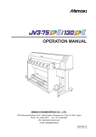
IP-7900
Read this User’s Guide carefully before use of this
printer and handle it properly.
After reading, keep it for later use.
Seiko I Infotech Inc.
IP-7900 Solvent Ink Color Inkjet Printer User's Guide
Documents Number U00112722602, Second Edition, November 2008
Copyright © 2008 by Seiko I Infotech Inc.
All rights reserved
Seiko I Infotech Inc. reserves the right to make changes without notice to the specifications and
materials contained herein and shall not be responsible for any damages (including consequential)
caused by reliance on the materials presented, including but not limited to typographical, arithmetic, or
listing errors.
Please address any questions, comments, and suggestions to :
Seiko Instruments Europe S.A.
European Head Office
Avenue de Messidor 198
1180 Brussels, Belgium
Phone : +32(0)2 346 62 74
Fax : +32(0)2 347 52 68
Seiko I Infotech, A Division of Seiko Instruments USA, Inc.
2060 Wineridge Place, Suite A, Escondido,
CA 92029, USA
Tel : +1-760-781-5200
Fax : +1-760-745-1195
Seiko I Infotech Inc.
8 Nakase 1-chome, Mihama-ku, Chiba-shi, Chiba 261-8507, Japan
Phone : +81 43 211 1363
Fax : +81 43 211 8709
This guide acknowledges the following trademarks :
is a trademark of Seiko Instruments Inc.
All other trademarks are the properties of their respective companies.
This equipment has been tested and found to comply with the limits for a Class A digital device,
pursuant to Part 15 of the FCC Rules. These limits are designed to provide reasonable protection against
harmful interference when the equipment is operated in a commercial environment.
This equipment generates, uses, and can radiate radio frequency energy and, if not installed and used
in accordance with the instruction manual, may cause harmful interference to radio communications.
Operation of this equipment in a residential area is likely to cause harmful interference in which case
the user will be required to correct the interference at his own expense.
The CE mark, that shows that the products sold in the EU are conformed to the requirements of EC
directive, is statutorily obliged to be affixed to the products.
In each directive, the scope of directive to be applied to equipment is explicitly defined. Our company’s
product IP-7900 conforms the EMC directive (2004/108/EC)) and low voltage directive (2006/95/EC).
Inquiry of CE mark:
Seiko Instruments Europe S.A.
European Head Office
Avenue de Messidor 198
1180 Brussels, Belgium
Phone : +32(0)2 346 62 74
Fax : +32(0)2 347 52 68
Seiko I Infotech, A Division of Seiko Instruments USA, Inc.
2060 Wineridge Place, Suite A, Escondido,
CA 92029, USA
Tel : +1-760-781-5200
Fax : +1-760-745-1195
Seiko I Infotech Inc.
8 Nakase 1-chome, Mihama-ku, Chiba-shi, Chiba 261-8507, Japan
Phone : +81 43 211 1363
Fax : +81 43 211 8709
Introduction
IP-7900 Solvent Ink Color Inkjet Printer (hereafter simply called the printer below.) is
equipped with built-in USB interface that adopts solvent ink and supports media of up to
104-inch width.
This guide, the IP-7900 Solvent Ink Color Inkjet Printer User’s Guide, describes such
information for use as features and names of parts of the printer and basic operations
including power ON/OFF and media/ink setting.
The following items should be read before reading Section 1.
• Delivery product
• Safety precautions
• Handling precautions
• Manual legend (notation rules)
Read these items to use the printer safely and properly. Keep this manual in a place where
you can quickly access it at any time.
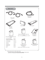
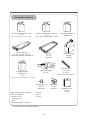
Components delivered with this product
The following components are delivered with the printer, and installed to the printer at
the printer installation, check that all the components below are clelivered.
If any item is missing or damaged, contact your dealer from whom you purchased the
printer or the nearest service depot.
Basic configuration item
Printer <1 unit>
• equipped with USB interface
• mounted with the roll feed unit
and take-up reel unit
Items packed with printer
Scroller <2 pieces>
Phillips screwdriver
Roll media (for adjustment)
<1 piece>
Waste ink bottle IP6-109
<1 bottle>
Rubber spacer A
<1 piece>
Rubber spacer B
<1 piece>
Pullout handle of scroller
<1 piece>
i
104-inch paper tube
(for take-up reel unit)
<1 piece>
Rubber spacer C
<1 piece>
Paper setting gauge
<1 piece>
Accessories
USB2.0 cable
<1 piece>
Power cable
<2 pieces>
Subcartridge*
Dummy pack
Ink tray
IP7-123
<8 pieces>
Wiper cleaning liquid set IP7-131
<1 set>
Daily maintenance kit IP7-130
<1 set>
• Cap cleaning liquid
• Wiper cleaning liquid
• Spittoon absorber liquid
• Cleaning roller
• Cleaning swab
• Dripper
• Tweezers
• Cleaning stick
• Spittoon case
• Gloves
• Bag
: 300 ml
: 200 ml
: 100 ml
: 30 pieces
: 10 pieces
: 10 pieces
: 1 piece
: 1 piece
: 1 piece
: 30 pairs
: 1 piece
• Wiper cleaning liquid (200 ml) : 3 bottles
Spittoon absorber
liquid IP7-132
<1 set>
• Spittoon absorber liquid(100 ml) : 3 bottles
* Subcartridge consists of the colors below.
(1) Y, M, C, K, Lm, Lc, Gy, and Lgy (1pc for each) for 8-color mode
(2) Y, M, C, and K (2pcs for each) for 4-color mode
ii
User’s Guide
(this guide)
<1 volume>
Wiper cleaning liquid
extraction set
Option
• Exhaust attachment
• PS RIP (PhotoPrint 6 Standard SIIT Edition)
• PS RIP (PhotoPrint 6 Server SIIT Edition)
• Mesh printing kit
• Footswitch
• Scroller
• Color exchange set
Cleaning liquid pack
Dummy subcartridge
:2
:1
:1
:1
:1
:1
:1
:4
:4
* Options can be ordered separately.
Consumables
Subcartridge (8 colors)
(Y, M, C, K, Lc, Lm, Gy, Lgy)
Daily maintenance kit IP7-130
<1 set>
• Cap cleaning liquid
• Wiper cleaning liquid
• Spittoon absorber liquid
• Cleaning roller
• Cleaning swab
• Dripper
• Tweezers
• Cleaning stick
• Spittoon case
• Gloves
• Bag
: 300 ml
: 200 ml
: 100 ml
: 30 pieces
: 10 pieces
: 10 pieces
: 1 piece
: 1 piece
: 1 piece
: 30 pairs
: 1 piece
Cleaning liquid kit IP7-136
<1 set>
Storage liquid kit IP7-137
<1 set>
• Cleaning liquid pack : 8 pieces
• Dummy subcartridge : 8 pieces
• Storage liquid pack : 8 pieces
• Dummy subcartridge : 8 pieces
iii
Consumables (continued)
Cap cleaning liquid set IP7-134
<1 set>
Wiper cleaning liquid set IP7-131
<1 set>
• Cap cleaning liquid (300 ml) : 3 bottles
• Wiper cleaning liquid (200 ml) : 3 bottles
Ink pack (8 colors)
(Y, M, C, K, Lc, Lm, Gy, Lgy)
As for part number, refer to P.1-6.
Waste ink bottle
IP6-609
<1 bottle>
Ink tray
IP7-123
<8 pieces>
Head cleaning kit
IP7-125
Spittoon absorber
liquid IP7-132
<1 set>
Cleaning swab IP6-147
<300 pieces>
Cleaning stick
IP5-120
<1 piece>
(with one cleaning roller)
• Spittoon absorber liquid(100 ml) : 3 bottles
Cleaning roller set
IP5-121
<90 pieces>
Wiper cleaning liquid <1 bottle>
Glove set <100 sets>
Spittoon case set
• Spittoon case
• Bag
Absorbent sponge <10 pieces>
IP7-135
IP7-138
IP7-126
* Consumables can be ordered separately.
iv
Wiper blade
IP7-133
<8 pieces>
Absorbent sheet
IP7-124
<1 roll>
Safety precautions
The following symbols are used in this manual to ensure the proper use of the printer and
to prevent the printer from being damaged.
Follow the instructions marked with these symbols.
WARNING
Serious personal injury or death:
Failure to follow the guidelines marked with
this symbol could result in serious personal
injury or death.
CAUTION
Minor personal injury or product and/ or
peripheral damage:
Failure to follow the guidelines marked with
this symbol could result in minor personal
injury or product and/or peripheral damage.
Example of symbols :
This symbol ( ) denotes items that require special care while
executing a certain procedure or operation.
This symbol (
) denotes items that are forbidden.
This symbol (
) denotes items you should follow to prevent
accidents or injury.
v
WARNING
Be sure to read warnings below before use.
Use the power supply voltage specified on the nameplate. DO NOT plug several
devices into one electrical outlet as this may result in fire or electric shock.
Make sure the printer is well grounded. If not, a short circuit may cause fire or
electric shock.
DO NOT disassemble or remodel the printer. Doing so may cause an accident or a
breakdown.
DO NOT damage, break, process, or heat the power cable. If it is damaged, replace
it with a new one. Using a damaged power cable may cause fire or electric shock.
NEVER use the printer in a place of extreme humidity or any place where it can
possibly be splashed by any liquids. If any liquid gets into the printer, it could lead
to fire, electric shock, or a breakdown.
DO NOT remove the secured covers of the printer because they cover highvoltage and extremely hot parts. Careless removal might result in electric shock or
burn.
DO NOT allow metal or liquids to touch the internal parts of the printer.
Doing so may cause fire, electric shock, or a breakdown.
DO NOT disconnect or connect the power cable with wet hands. Doing so may
lead to electric shock.
Turn the printer off and unplug the power cable from the power outlet
immediately after it thundered.
Turn the printer off and unplug the power cable from the power outlet in any of
the following cases: Using the printer continuously in an abnormal state may result
in an accident or fire.
– When putting your hands inside the printer.
– Smoke, strange noise or smell is generated from the printer or the printer is
overheated.
– A piece of metal or any liquid touches the internal parts or slot of the printer.
– An error requiring service by a service center occurs.
DO NOT put your hand unnecessarily inside the printer such as covers, ventilator
opening and ink cartridge slot. Doing so may result in personal injury. Even if the
printer is not operating, it may perform a function automatically. Use caution with
the printer even if it is not printing.
NEVER put any ink cartridge close to fire as this may cause fire, since the ink is
flammable containing petroleum solvent.
vi
Do not swallow ink or avoid its splashes on the eye to prevent breathing trouble
or visual impairment. If ink gets into the eye, wash it off with clean running water
and consult a doctor. If it is swallowed, do not try to vomit it forcefully, but consult
a doctor.
Keep ink cartridges out of reach of children.
If the printer is stained with ink, remove the ink from the printer immediately.
If the printer is left stained, parts may be broken or the surface paint may come off.
CAUTION
Ensure to read cautions below before use.
Since media rolls are heavy, handle them with care. If you drop them on your foot,
you may be injured.
Always hold the power cable or USB cable by the plug or the connector when
connecting or disconnecting the power cable or USB cable.
Never pull the cable directly because this may damage it, which may result in fire,
electric shock, a breakdown, or personal injury.
DO NOT get ink on your skin or clothes. Wash off any ink immediately with soapy
water.
DO NOT place the printer on an unstable table or at a slant place. If it falls, it may
lead to injury.
DO NOT place media rolls on tables ot unlevel areas where it could fall. If dropped
or falls, it may lead to injury. To prevent falling, lock the casters.
DO NOT touch the heater to avoid burn as it becomes hot.
In order to ensure safe operation of the printer, heed all the warnings and cautions
contained throughout this manual.
vii
Handling precautions
Power supply
1. Install the printer near an easily accessible electrical outlet.
2. Do not provide power to the printer through the same power line as for noisegenerating devices, such as a motor.
3. Use the power supply specified on the nameplates of printer and option.
4. Connect the power cable to an electrical outlet. Do not plug several devices into one
electrical outlet.
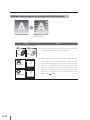
Printer
1. Do not place anything on top of the printer. Do not rest your elbows on the printer.
Especially be careful not to block the printer's exhaust outlet shown by the figure
below.
2. Do not apply shock or stress to the printer.
3. When opening or closing the front cover, hold it with both hands and open or close it
gently.
4. Before connecting or disconnecting the interface connector, turn the printer off.
5. Do not clean the surface of the cover with benzene or paint thinner. The coating may
come off or deteriorate.
Clean the cover with a soft cloth. If the cover is very dirty, wipe it off with a cloth
moistened with water-diluted neutral detergent.
6. Handle a print head with care.
- Do not touch it unnecessarilyn or scratch it.
- Do not touch the bottom (nozzle surface).
Periodic inspection and maintenance
As the intrinsic characteristics of solvent ink, the regular periodic inspection and
maintenance must be performed.
1. Clean the capping unit and the wiper blade everyday.
2. Check visually the remaining wiper cleaning liquid everyday.
3. Clean the print head every month.
4. Perform the service cleaning when leaving the printer for two weeks or more in a
power-off state.
5. Perform the head wash and the ink charge before printing again after the printer is left
for a long time.
For various periodic inspection and maintenance, refer to P.2-108 to P.2-120.
viii
Consumables
1. Always use the specified ink. Failure to follow this instruction may cause poor print
quality or a breakdown.
2. Do not use expired ink as this may cause a breakdown.
3. Put used ink packs into a plastic bag and dispose of them as industrial waste. Observe
local regulations for disposal of consumables.
4. Do not get ink on your skin or clothes. If ink touches your skin, wash it off immediately
with soapy water.
5. Check the level of the waste ink bottle regularly to prevent overflow.
6. When removing the waste ink bottle, spread a sheet so as not to stain the floor with
spilt ink.
7. Store ink in a dark and cool place. Keep away from high-temperature and direct
sunlight.
Doing so may deteriorate ink characteristic.
8. Do not disassemble ink pack.
Printer warranty
1. To understand the printer's performances and functions well and use the printer safely,
be sure to read this guide.
2. The use of consumables, accessories and options other than our products specified by
Seiko I Infotech Inc. affects print image quality and causes damage to the print, which
prevents maintenance. Never use unspecified consumables, accessories or options.
3. To secure the quality, the expiration dates of use and installation are indicated on ink,
storage liquid, cap cleaning liquid, and wiper cleaning liquid.
– Expiration date of installation:
The expiration date of installation is indicated on the packaging box or the printer.
Install them to the printer before the date.
– Expiration date of use:
Do not use it after expired.
ix
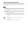
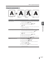
Manual legend (Notational rules)
The notational rules such as marks, keys, LCD, and LEDs used for explanation in this guide
are as follows:
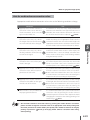
Marks
WARNING
– Boxes marked with a "WARNING" describe points of caution for avoiding serious
personal injury.
CAUTION
– Boxes marked with a "CAUTION" describe points of caution for avoiding injury to
yourself or damage to the printer.
Note
– They explain the important items and cautions that should be kept for operation
of the printer.
HINT: Hint mark
This mark describes operations that make using or handling the printer easier.
Reference mark
This mark is followed by a reference section or page number.
x
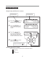
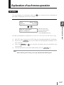
Key / LCD / LED marks
(Example 1) Keys and LCD marks in a sentence
It shows the LCD on
the operation panel.
It shows the key on
the operation panel.
1
Press the O N L I N E key to
display the menu group.
2
Press the M E N U key to
change the menu group
screen.
3
4
INK
MEDIA
REWIND
PH.REC
Press the M E N U key
once more to display the
menu group screen that
contains the function menu.
MEDIA REG M.ADV FORM FEED PH.MAIN PRINTER
SE TUP HEATER ADJUST
Press the
key to enter
the function menu.
OK
It shows the key used for selection.
(Example: Select SETUP =
key)
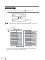
(Example 2) LED marks in a sentence
The ON, blinking, and OFF states of LEDs are indicated as follows:
ON (lighting)
Blink
OFF (lights-out)
xi
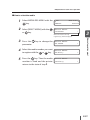
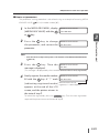
(Example 3) Transition of LCD state and the key operation in a sentence
INITIALIZING...
PLEASE WAIT
It shows that the LCD menu automatically
changes in the arrow direction without
key operation.
PRINTER READY
R O L L 㧦104/PAPER
It shows that the LCD menu changes
in the arrow direction with key operation.
INK
MEDIA
MEDIA REG M.ADV It shows the key on
the operation panel.
REWIND
PH.REC
FORM FEED PH.MAIN xii
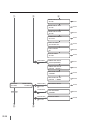
TABLE OF CONTENTS
Components delivered with this product ______________________________ i
Safety precautions
____________________________________________
Handling precautions
_________________________________________
Manual legend (Notational rules)
v
viii
__________________________________
x
Overview
Operating conditions __________________________________________________1-2
Installation space .....................................................................................................................................................1-2
Environmental conditions ..................................................................................................................................1-3
Consumables _________________________________________________________1-4
Media ...............................................................................................................................................................................1-4
Ink pack ..........................................................................................................................................................................1-6
Waste ink bottle ........................................................................................................................................................1-8
Daily maintenance kit ...........................................................................................................................................1-9
Cap cleaning liquid set .........................................................................................................................................1-9
Wiper cleaning liquid set ....................................................................................................................................1-9
Wiper cleaning liquid ......................................................................................................................................... 1-10
Cleaning swab ........................................................................................................................................................ 1-10
Storage liquid kit ................................................................................................................................................... 1-10
Cleaning liquid kit ................................................................................................................................................. 1-10
Head cleaning kit .................................................................................................................................................. 1-10
Spittoon absorber liquid .................................................................................................................................. 1-11
Subcartridge............................................................................................................................................................. 1-11
Wiper blade .............................................................................................................................................................. 1-11
Cleaning stick .......................................................................................................................................................... 1-11
Cleaning roller set................................................................................................................................................. 1-11
Spittoon case set ................................................................................................................................................... 1-12
Ink tray ......................................................................................................................................................................... 1-12
Glove set ..................................................................................................................................................................... 1-12
Absorbent sponge (Option for mesh banner) ................................................................................... 1-12
Absorbent sheet (Option for mesh banner) ........................................................................................ 1-12
Appearance / Name and function of each part ____________________________1-13
Printer front (takeup side) ................................................................................................................................ 1-13
Printer rear (supply side)................................................................................................................................... 1-14
Printer heater unit ................................................................................................................................................ 1-15
Operation panel..................................................................................................................................................... 1-16
Options _____________________________________________________________1-18
Footswitch (IP7-014) ........................................................................................................................................... 1-18
Scroller (IP7-015) .................................................................................................................................................... 1-18
Exhaust attachment (IP7-013) ....................................................................................................................... 1-18
PS RIP (PhotoPrint 6 Standard SIIT Edition) (IP-550) ........................................................................ 1-18
PS RIP (PhotoPrint 6 Server SIIT Edition) (IP-551) ............................................................................... 1-18
Mesh printing kit (IP7-011) .............................................................................................................................. 1-18
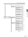
C-1
Basic operation
Connection to a computer ______________________________________________2-2
System configuration (Connection example) ........................................................................................2-2
Connecting procedure .........................................................................................................................................2-2
Power ON/OFF procedure ______________________________________________2-3
Power-on procedure .............................................................................................................................................2-4
Power-off procedure 1 .........................................................................................................................................2-6
Power-off procedure 2 .........................................................................................................................................2-6
Media installation and removal __________________________________________2-7
Roll media installation procedure .................................................................................................................2-7
Procedure to install general roll media to the take-up reel unit ............................................ 2-16
Procedure to load PVC (Vinyl Chloride) roll media on TUR in LOOSE winding mode2-22
Cut-sheet media installation/removal procedure ............................................................................ 2-28
Procedure to remove media (scroller) from the printer ............................................................... 2-30
Procedure to remove media from the scroller ................................................................................... 2-37
When no media is loaded on the scroller.............................................................................................. 2-37
When replacing roll media due to jamming ....................................................................................... 2-37
Setting media advance correction values ............................................................................................. 2-38
Adjusting the print head position [ADJUST PH POS] ..................................................................... 2-41
Adjusting the print head nozzles' R/L position [ADJUST PH R/L] ........................................... 2-43
Adjusting the print head’s bidirectional position [BIDIRECTION]...................................... 2-46
Ink pack installation and replacement ___________________________________2-49
Ink pack installation/replacement procedure..................................................................................... 2-49
Replacing ink pack when ink is exhausted ........................................................................................... 2-52
When no ink pack is installed ........................................................................................................................ 2-55
Service clean ............................................................................................................................................................ 2-55
Head wash................................................................................................................................................................. 2-61
8-color to 4-color mode change procedure ........................................................................................ 2-67
4-color to 8-color mode change procedure ........................................................................................ 2-75
When the ink pack is not recognized....................................................................................................... 2-84
When the ink charge from ink tray is not completed .................................................................... 2-84
Waste ink bottle installation and replacement ____________________________2-87
Waste ink bottle installation procedure.................................................................................................. 2-87
Procedure when the waste ink bottle becomes full....................................................................... 2-88
Procedure when no waste ink bottle is installed .............................................................................. 2-89
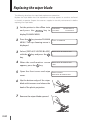
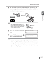
Replacing the wiper blade _____________________________________________2-90
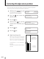
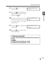
Correcting the edge sensor position _____________________________________2-92
Adjusting tension bar length ___________________________________________2-94
Print head cleaning ___________________________________________________2-95
Print head cleaning procedure .................................................................................................................... 2-95
Feeding the media [Feed]______________________________________________2-97
Backfeeding the media [Backfeed] ______________________________________2-98
Nest function ________________________________________________________2-99
Changing temperature using the heater control menu ____________________2-101
How to use the pressure control knob __________________________________2-105
C-2
How to use the head up/down mechanism ______________________________2-106
How to use media edge guards ________________________________________2-107
Periodic maintenance ________________________________________________2-108
Periodic inspection/maintenance guide ............................................................................................ 2-108
Daily inspection and maintenance ......................................................................................................... 2-109
Bimonthly inspection and maintenance ............................................................................................ 2-118
Maintenance conducted when leaving the printer in the power-off state for more than
two weeks .............................................................................................................................................................. 2-121
Maintenance conducted when operating the printer after power-off for more than two
weeks......................................................................................................................................................................... 2-122
Maintenance conducted when operating the printer after power-off for less than two
weeks......................................................................................................................................................................... 2-124
Maintenance conducted when the printer has been left in the power-off state for more
than one month ................................................................................................................................................. 2-125
Cleaning................................................................................................................................................................... 2-126
Menu of operation panel
LCD display and state of the printer ______________________________________3-2
How to read LCD display ....................................................................................................................................3-2
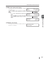
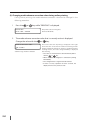
Online operation ______________________________________________________3-6
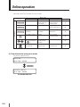
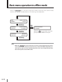
Basic menu operation in offline mode ___________________________________3-12
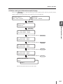
Menu layer structure........................................................................................................................................... 3-13
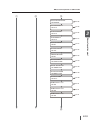
Menu tree .................................................................................................................................................................. 3-14
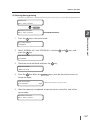
Basic operation procedure and keys used ............................................................................................ 3-20
Procedure for selection input, numeric input, execution, and character input ............ 3-21
Explanation of each menu operation ____________________________________3-27
INK MENU................................................................................................................................................................... 3-27
MEDIA MENU ........................................................................................................................................................... 3-28
MEDIA REG MENU ................................................................................................................................................ 3-30
M.ADV MENU ........................................................................................................................................................... 3-46
REWIND MENU ....................................................................................................................................................... 3-49
PH.REC MENU .......................................................................................................................................................... 3-49
FORM FEED MENU ............................................................................................................................................... 3-50
PH.MAIN MENU ...................................................................................................................................................... 3-50
PRINTER MENU ....................................................................................................................................................... 3-53
ADJUST MENU ........................................................................................................................................................ 3-54
SETUP MENU ............................................................................................................................................................ 3-57
HEATER MENU ........................................................................................................................................................ 3-62
Print mode and special printing
Print mode and special printing _________________________________________4-2
Print modes .................................................................................................................................................................4-2
Double-sided printing ..........................................................................................................................................4-3
Mesh banner printing ...........................................................................................................................................4-3
Double-sided printing _________________________________________________4-4
C-3
Troubleshooting
When encounting a problem ____________________________________________5-2
Power is not turned on. .......................................................................................................................................5-2
The paper guide does not heat after the heater is turned on. ....................................................5-2
The printer does not start or operate normally. ...................................................................................5-2
Printing is disabled..................................................................................................................................................5-3
Although the printer is in the print mode, printing does not start with "PREHEATING"
displayed on the operation panel. ................................................................................................................5-3
The transmitted data is not printed. ............................................................................................................5-3
Print quality is not good. .....................................................................................................................................5-3
Blank sheet appears. ..............................................................................................................................................5-4
Media jam occurs frequently. ...........................................................................................................................5-4
Print speed is low. ....................................................................................................................................................5-4
The menu is displayed in another language. .........................................................................................5-5
How to clear media jams _______________________________________________5-6
When an error message is displayed ______________________________________5-8
Service call errors .....................................................................................................................................................5-8
Operator call errors .................................................................................................................................................5-9
When a warning message is displayed ___________________________________5-15
How to get good image quality _________________________________________5-16
The print is light. .................................................................................................................................................... 5-16
White stripes appear on the print. ............................................................................................................. 5-16
Black stripes appear on the print. ............................................................................................................... 5-18
The print is contaminated. .............................................................................................................................. 5-19
Bleeding occurs on the print. ........................................................................................................................ 5-20
Nozzle-out occurs at the beginning of printing................................................................................ 5-20
A vertical barding appears at the end of the print. ......................................................................... 5-21
Different banding appear on the right and left of the print. ..................................................... 5-22
Hint for media advance correction value .............................................................................................. 5-23
When abnormal sound is produced _____________________________________5-24
To move the printer __________________________________________________5-25
Appendix
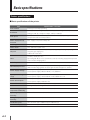
Basic specifications ___________________________________________________ A-2
Printer specifications............................................................................................................................................. A-2
Footswitch (option) ___________________________________________________ A-3
How to use the footswitch ............................................................................................................................... A-3
Usage notes................................................................................................................................................................ A-3
Components .............................................................................................................................................................. A-4
Installation ................................................................................................................................................................... A-4
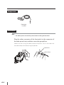
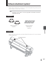
Exhaust attachment (option) ___________________________________________ A-5
Components .............................................................................................................................................................. A-5
Installation ................................................................................................................................................................... A-5
1
Overview
This section describes the information (basic knowledge)
needed before using the printer. After reading this section,
proceed to section 2.
(Content of this section)
Operating conditions ......................................................................1-2
Consumables........................................................................................1-4
Appearance / Name and function of each part ...........1-13
Options .................................................................................................1-18
Operating conditions
This section describes the operating conditions required for the printer.
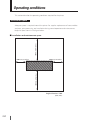
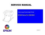
Installation space
Adequate space is required around the printer for supplies replacement of consumables
and parts, print processing, and ventilation during normal operation and maintenance.
Keep the space shown in the figure below.
1000 mm, 40 inches
Installation and maintenance space
400 mm, 16 inches
400 mm, 16 inches
1000 mm, 40 inches
(Front side)
Height direction: 2200
(Unit: mm)
1-2
Operating conditions
Environmental conditions
Operating temperature and humidity levels
Temperature: 15°C to 30°C (60°F to 80°F)
Humidity: 30% to 70%
Overview
Use the printer within the temperature and humidity levels shown below.
1
To obtain better print quality, use the printer within a temperature range of 20 to 25°C
(68 to 77°F).
To keep a stable and good print quality, the printer slows down the print speed when
the head temperature exceeds 40°C (104°F).
Note
– If the printer is used out of the operating temperature and humidity ranges, the
print may be stopped or the print quality may be degraded.
– It takes time for the printer to reach the operating environment temperature and
humidity. To get good print image quality, it is recommended to keep the room
temperature 20 to 25°C, 68 to 77°F and use the printer after 1 hour.
Places where the printer must not be installed
Do not install the printer in the following places.
Places near fire
Places exposed to direct sunlight
Places subject to vibration
Places with excessive dust
Places subject to extreme changes in temperature or humidity
Places near an air conditioner or a heater
Places where the printer may get wet
Places exposed to direct exhaust air from an air vent
Places near a diazo copier that may generate ammonia gas
Places with poor ventilation
Unstable places
1-3
Consumables
Media
Type of media
The following recommended media are provided.
For details, contact your dealer or Seiko I Infotech sales.
–
–
–
–
–
Vinyl chloride
Flexible face
Banner
Mesh banner
Cloth
Precautions for storing media
Avoid direct sunlight and water regardless of before and after opening the package.
Put media in the packing box to prevent dust and store media in a cool and dark place.
Avoid rapid change of temperature and humidity and store media with no
condensation.
Do not store media in an upright condition to prevent winding deviation of media and
damage of roll edge.
Do not pile up media.
Precautions for disposing of media
Dispose of media in a manner consistent with local regulation. Observe any regulations
for disposal of consumables.
1-4
Consumables
Precautions for preparing media
Avoid a change of temperature and humidity after opening package. Load media
media in high humidity occur easily. Use paper in normal temperature and humidity
environment (around 23°C, 73°F and 50% RH).
Do not use scratched, wrinkled, curled, or dust-stained part of media. Especially, both
Overview
after leaving media in the operation environment for 3 hours or more. Be cautions of a
change of humidity by turning ON/OFF the air conditioner.
In terms of media characteristics, curl of paper in low humidity and wrinkles of
1
edges of roll affect media feeding. Also, do not drop or wet the media. Doing so may
adversely affect print quality and may cause a printer's malfunction.
Hold edges of the media so as not to touch the print surface. Adhesion of sebaceous
matter or sweat may degrade print quality.
Correct distortion of roll media before loading.
Precautions for handling prints
Do not touch the print surface before the ink dries (within 24 hours after printing in
particular). Handle by edges of the media.
Rubbing print surface causes color fading or color transfer. Do not contact print
surfaces to prevent color transfer.
Do not put printed matters on printouts from copier or laser printer. They may adhere
to each other due to ink or toner. Also, do not place the printed media directry on the
wax-coated floor. This may damage the prints.
Do not rub, scratch or fold the printed surface of media. If done so, the print on the
surface may come off.
Do not rub or leave wet prints to prevent blurring or loss of print.
Other precautions of media
Media causes color fading and a change in quality in getting old.
Paper dust generated when cutting media may cause laminate peeling-off.
When self-adhesive media is used, the adhesive may adhere to the platen or other
parts. This may cause a media jam. Wipe it off referring to [Section 2 Basic operation].
1-5
Ink pack
Ink types
Use only the recommended ink packs listed below.
[8-color ink] One box contains one ink pack.
Type
Ink color
Quantity
IP7-101
Y (yellow)
1500 ml
IP7-102
M (magenta)
1500 ml
IP7-103
C (cyan)
1500 ml
IP7-104
K (black)
1500 ml
IP7-105
Lc (light cyan)
1500 ml
IP7-106
Lm (light magenta)
1500 ml
IP7-107
Gy (gray)
1500 ml
IP7-108
Lgy (light gray)
1500 ml
Note
– Always use these specified ink packs. Failure to use the recommended ink pack
may lead to a deterioration of the print quality or a printer malfunction. This may
invalidate your warranty.
– The ink validity period is 12 months from the date of production.
– Do not shake these ink packs before using them.
– Install ink packs and ink trays to all the 8 slots. When you remove ink packs or ink
trays, be sure to install new ones instead.
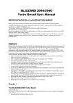
1-6
Consumables
Ink packs and ink trays must be installed in all eight slots. The positions of ink packs are
specified by color. (See the figure below.)
Ink box
Lg (light gray)
Slot No. 8
M (magenta)
Slot No. 7
Lc (light cyan)
Slot No. 6
K (black)
Slot No. 5
Y (yellow)
Slot No. 1
Lm (light magenta)
Overview
8-color mode
1
Slot No. 2
C (cyan)
Slot No. 3
Gy (gray)
Slot No. 4
4-color mode
Y (yellow)
M (magenta)
Y (yellow)
M (magenta)
C (cyan)
C (cyan)
K (black)
K (black)
WARNING
– Never bring ink close to fire. Failure to follow this warning may result in fire.
CAUTION
– Do not swallow ink or avoid its splashes on the eye to prevent breathing trouble
or visual impairment. If ink gets into the eye, wash it off with clean running
water and consult a doctor. If it is swallowed, do not try to vomit it forcefully, but
consult a doctor.
Precautions for ink storage and processing
CAUTION
– Put used ink packs into a plastic bag and dispose of them as industrial waste.
Observe any regulations for disposal of consumables.
Note
– Ink has a validity period. Using expired ink may degrade print quality and cause a
printer malfunction.
– Store ink packs in a cool and dark place. Always use the specified ink. Using
unspecified ink may cause poor print quality or a breakdown, which may prevent
maintenance.
1-7
Waste ink bottle
Use the recommended waste ink bottle listed below.
Type
IP6-109
Content
Waste ink bottle
Quantity
1 piece
WARNING
– Never put the waste ink bottle close to fire. Failure to follow this warning may
result in fire.
CAUTION
– Do not swallow ink or avoid its splashes on the eye to prevent breathing trouble
or visual impairment. If ink gets into the eye, wash it off with clean running
water and consult a doctor. If it is swallowed, do not try to vomit it forcefully, but
consult a doctor.
Note
– Install the waste ink bottle securely.
– A waste ink bottle must always be installed. When it is removed for disposal of
waste ink, another empty waste ink bottle must be installed.
Precautions for handling the waste ink bottle
CAUTION
– When the waste ink bottle becomes full, securely fasten the attached cap and
dispose of the bottle as industrial waste.
Note
– If you cannot dispose of waste ink, contact the sales dealer or nearest service
depot. Be sure to tighten the caps of waste ink bottles and put them in bags so
that the ink does not leak. Then put the bags in cardboard boxes and send the
cardboard boxes to the collection center.
1-8
Consumables
Daily maintenance kit
1
Use the recommended cleaning liquid listed below for cap and wiper cleaning.
Content
300 ml
Wiper cleaning liquid
200 ml
Spittoon absorber liquid
IP7-130
Quantity
Cap cleaning liquid
100 ml
Dripper
10 pieces
Cleaning swab
10 pieces
Cleaning stick
1 piece
Cleaning roller
30 pieces
Tweezers
Overview
Type
1 piece
Spittoon case
1 piece
Gloves
30 pieces
Bag
1
CAUTION
– Do not swallow cleaning liquid or avoid its splashes on the eye to prevent
breathing trouble or visual impairment. If cleaning liquid gets into the eye, wash
it off with clean running water and consult a doctor. If it is swallowed, do not try
to vomit it forcefully, but consult a doctor.
Cap cleaning liquid set
Type
IP7-134
Content
Cap cleaning liquid (300 ml)
Quantity
3 bottles
Wiper cleaning liquid set
Type
IP7-131
Content
Quantity
Wiper cleaning liquid (200 ml)
3 bottles
1-9
Wiper cleaning liquid
Type
IP7-135
Content
Quantity
Wiper cleaning liquid (200 ml)
1 bottle
Content
Quantity
Cleaning swab
Type
IP6-147
Cleaning swab
300 pieces
Bag
6 pieces
Storage liquid kit
Type
IP7-137
Content
Quantity
Storage liquid pack
8 pieces
Dummy subcartridge
8 pieces
Cleaning liquid kit
Type
IP7-136
Content
Quantity
Cleaning liquid pack
8 pieces
Dummy subcartridge
8 pieces
Head cleaning kit
Type
IP7-125
1-10
Content
Quantity
Head cleaning sheet
6 sheets
Support sheet
1 pieces
Platen sheet
1 pieces
Manual
1 pieces
Consumables
Spittoon absorber liquid
Type
Spittoon absorber liquid (100 ml)
Quantity
3 bottles
Subcartridge
Type
Ink color
1
Overview
IP7-132
Content
Quantity
IP7-111
Y (yellow)
400 ml
IP7-112
M (magenta)
400 ml
IP7-113
C (cyan)
400 ml
IP7-114
K (black)
400 ml
IP7-115
Lc (light cyan)
400 ml
IP7-116
Lm (light magenta)
400 ml
IP7-117
Gy (gray)
400 ml
IP7-118
Lgy (light gray)
400 ml
Wiper blade
Type
IP7-133
Content
Wiper blade
Quantity
8 pieces
Cleaning stick
Type
IP5-120
Content
Quantity
Cleaning stick
1 piece
Cleaning roller
1 piece
Cleaning roller set
Type
IP5-121
Content
Cleaning roller
Quantity
90 pieces
1-11
Spittoon case set
Type
IP7-126
Content
Quantity
Spittoon case
1 piece
Bag
1 piece
Ink tray
Type
IP7-123
Content
Ink tray
Quantity
1 piece
Glove set
Type
IP7-138
Content
Gloves
Quantity
100 pairs
Absorbent sponge (Option for mesh banner)
Type
IP7-127
Content
Absorbent sponge
Quantity
10 pieces
Absorbent sheet (Option for mesh banner)
Type
IP7-124
1-12
Content
Absorbent sheet
Quantity
1 roll
Appearance / Name and function of each part
This section shows the printer appearance and describes the name and function of each
component.
Overview
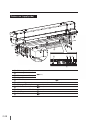
Printer front (takeup side)
1
Lock
(ON)
Unlock
(OFF)
Operation panel
Ink box cover
Tension bar guide
Caster
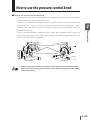
Pressure control knob
Front cover
Waste ink bottle unit
Cap cover
Wipe cover
Take-up direction switch
Media feed switch
Take-up reel switch
Footswitch connector
Scroller
Media dryer fan
Protection bar
Provided with LEDS and LCD to display printer status and keys to set
functions.
An inlet to set ink (Note: Displayed as “INK COVER” on the LCD.)
The guide of bar to apply tension to the media (
P.2-21)
Unlocked to move the printer and locked to immobilize it.
A knob to switch the media press force (
P.2-105)
Must be closed during printing.
A unit to contain a waste ink bottle (
P.2-87)
Opened when cleaning the capping unit or replacing the wiper
blade. (
P.2-111, P.2-114)
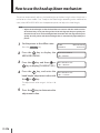
Opened when maintaining the print head (replacement/height
adjustment). (
P.2-90)
A switch to select media takeup direction (
P.2-17)
A switch to feed media automatically (
P.2-14)
A switch to wind media automatically (
P.2-31)
A connector to connect optional Footswitch (
A shaft to feed or wind media (
P.A-3)
P.2-7)
A fan to dry ink after printing.
A bar to protect media surface just after the print.
1-13
Printer rear (supply side)
1-14
Printer power inlet
Printer power switch
Heater power inlet
Heater power switch
USB connector
Subcartridge
Take-up reel switch
Media feed switch
Pressure control knob
Scroller
Peel roller
(
P.2-3)
Connected to the printer server. (
P.2-2)
An auxiliary ink for printing even during replacement of ink
(
P.2-14)
(
P.2-14)
(
P.2-105)
(
P.2-7)
(
P.2-14)
Appearance / Name and function of each part
Printer heater unit
This printer is equipped with three heaters for ink fusing and image quality stabilization.
Takeup side
(rear)
(front)
Overview
Supply side
1
Head
Media
Preheater (rear)
Print heater (front)
Afterheater (finishing)
Preheats media.
Penetrates ink into media to fuse the ink.
Dries ink to stabilize print quality.
* These three heaters are controlled independently.
The temperature of each heater can be controlled from the operation panel and the host PC (RIP).
( P.2-101 Changing temperature using the heater control menu)
WARNING
– Do not touch these heaters to avoid burn as they become hot.
1-15
Operation panel
The keys, LEDs and LCD are laid on the operation panel of the printer as shown below. In
addition, the operation panel is also equipped with a buzzer function for attention in case
an error occurs or an invalid input is entered.
Buzzer
LCD Indicates printer status and menus.
E
A
B
OK
MENU
ONLINE
HEATER
CANCEL
C
D
Keys Used for menu operation and other
purposes of the printer.
Power switch
1-16
LEDs Indicate printer status with ON, OFF,
and blinking.
Appearance / Name and function of each part
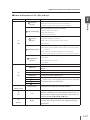
Name and function of LCD, LEDs, and keys
No. / Classification
Key
Power switch
Function
Indicates data reception state.
A Data LED
– Blink: Receiving data from the host computer.
(Green)
– OFF: No receiving data from the host computer.
Indicates whether an error has occurred.
– ON: An error has occurred.
B Error LED (Orange)
– Blink: Warning state.
– OFF: Normal (no error)
Indicates whether ink is remaining.
– ON: Ink of all colors is present.
C Ink LED
– Blink: Ink near-end (Ink of any color is little.)
(Green)
– OFF: No ink.
Indicates whether media is remaining.
– ON: Media is present (Either roll media or cut-sheet media is
loaded.)
D Media LED (Green)
– Blink: Take-up reel unit's operation was suspended.
– OFF: No media (Neither roll media nor cut-sheet media is loaded.)
Indicates online or offline state of the printer.
– ON: Online
E ONLINE LED
– Blink: Online pause mode
(Green)
– OFF: Offline
ONLINE key
Used to select online or offline of the printer.
Used for auxiliary parameter input (switching menu layer
MENU key
display).
CANCEL key
Used to cancel entered parameters.
OK key
Used to fix the selected menu and parameters.
HEATER key
Used to enter heater control menu.
key
Used to select a menu group and switch menu (selection,
key
key
increment/decrement of value)
key
Power switch
LCD
LCD
Buzzer
Buzzer
1
Overview
LED
Name
Used to turn on or off the power of the printer.
Displays messages and status of the printer in alphanumeric
characters, KANA characters and symbols (20 characters × 2
lines). The menu adopts a layered structure. Each menu can
be accessed with the , , , and keys.
Sounds when an error occurs or when invalid key operation
is made or when the print head is not capped in the daily
maintenance.
1-17
Options
Footswitch (IP7-014)
An optional footswitch to control the function of the take-up reel switch of the roll feed
unit and take-up reel unit, as well as to control the function of the media feed switch by
foot
Scroller (IP7-015)
An optional scroller available for both the roll feed unit and take-up reel unit
Exhaust attachment (IP7-013)
An optional unit to attach an exhaust duct to the printer
PS RIP (PhotoPrint 6 Standard SIIT Edition) (IP-550)
An optional RIP software program only for IP-7900
PS RIP (PhotoPrint 6 Server SIIT Edition) (IP-551)
An optional RIP software program only for IP-7900
Mesh printing kit (IP7-011)
Used to print mesh banner.
1-18
2
Basic operation
This section describes the basic operation of the printer such
as power on / off and media replacement procedure.
(Content of this section)
Connection to a computer ..........................................................2-2
Power ON/OFF procedure ............................................................2-3
Media installation and removal .................................................2-7
Ink pack installation and replacement................................2-49
Waste ink bottle installation and replacement ..............2-87
Replacing the wiper blade ........................................................2-90
Correcting the edge sensor position...................................2-92
Adjusting tension bar length ...................................................2-94
Print head cleaning ........................................................................2-95
Feeding the media [Feed] ..........................................................2-97
Backfeeding the media [Backfeed] .......................................2-98
Nest function .....................................................................................2-99
Changing temperature using the heater control menu ... 2-101
How to use the pressure control knob ........................... 2-105
How to use the head up/down mechanism ............... 2-106
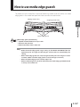
How to use media edge guards.......................................... 2-107
Periodic maintenance ............................................................... 2-108
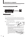
Connection to a computer
This section describes the procedure to connect the printer to a computer.
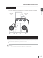
System configuration (Connection example)
The printer can be connected as follows:
Printer
USB interface
Printer server
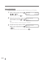
Connecting procedure
Connect the cable in the procedure below.
1
Turn off the power of the printer and the computer to be connected.
Note
– When the printer is connected to a PC, turn on the power of the printer first and
turn off the power of the printer last.
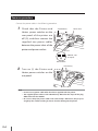
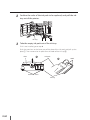
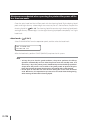
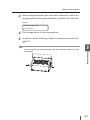
2
Connect the dedicated cable to
USB connector
the USB connector at the rear of
the printer.
Note
– Use the supplied USB2.0 cable.
USB2.0 cable (B-type connector)
– When using a USB hub, use a product that supports USB2.0.
– Use USB-IF certified products for cables and hub used for USB connections
and USB equipment to be connected to its system. Otherwise, the printer
may not function correctly.
– The maximum length of one cable is 5 m. If you want to extend the
connection length longer than 5m, use hubs. Up to five hubs can be
connected. However, if a cable longer than 5 m is used or only cables are
simply connected to each other, the printer may not function properly.
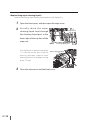
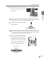
– To protect the USB connector,
clamp the USB2.0 cable to the
printer body as shown in the right
figure.
2-2
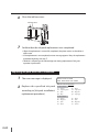
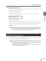
Power ON/OFF procedure
The printer is provided with two power lines. Note that both of them are 200 VAC.
Printer power switch + Printer power inlet
2
Basic operation
Heater power switch + Heater power inlet
Turn on the Printer power switch and Heater power switch first, and then use the power
switch on the operation panel of the printer to turn on or off the power.
2-3
Power-on procedure
Connect the power cables in the following procedure.
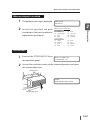
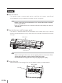
1
Check that the Printer and
Switch off (O)
Power inlet
Heater power switches on the
rear panel of the printer are
off (O), and then connect the
supplied two power cables
between the power inlets of the
printer and power outlets.
200 VAC, 15A
(in Japan)
Power outlet
Switch on (I)
2
Turn on (I) the Printer and
Heater power switches on the
rear panel.
Note
– Do not use any power cable other than those supplied with the printer.
– The supplied power cables are for 200 VAC only. Note that the shape of the plug
differs from that for 100 VAC.
– Be sure to clamp the power cables with cable clamps. Otherwise, they may be
caught by the scroller resulting in electric shock or damage to the printer.
2-4
Power ON/OFF procedure
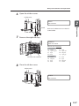
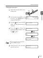
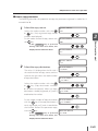
3
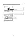
Turn on the power switch on the operation panel.
Power ON/OFF
switch
OK
ONLINE
HEATER
CANCEL
When the power switch is turned on, the printer performs the power-on selfdiagnostic test and displays the following message on the operation panel.
2
Basic operation
MENU
Booting up...
INITIALIZING...
PLEASE WAIT
PRINTER READY
ROLL:1625/PAPER
Note
– Except for emergency, turn off the power while a message "PRINTER READY" is
displayed. If the power is turned off unnecessarily when the printer is performing
"INITIALIZING..."or "CLEANING," the ink may drip or the print head may be
damaged or saved parameters may be lost.
– If the POWER LED on the operation panel does not light even when the Printer and
Heater power switches at the rear of the printer and the power ON/OFF switch on the
operation panel are turned on, the power supply has a problem.
– When an abnormality is detected during the power-on self-diagnostic test, an error
message appears on the LCD.
Take appropriate measures referring to [Section 5 Getting troubled].
2-5
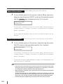
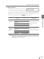
Power-off procedure 1
1
* When rebooting the printer within 20 hours
To turn off the power of the printer without fillcap operation,
keep pressing the power ON/OFF switch on the operation panel
and the
CANCEL
key simultaneously for 2 to 3 seconds.
SHUTTING DOWN
PLEASE WAIT
The message is displayed on the LCD as shown above, indicating that the
shutdown process is in progress. The power is turned off after the shutdown
process is completed.
Use this power-off procedure when an error or host communication error has
occurred.
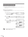
Power-off procedure 2
1
* When leaving the printer in power-off state for more than 20 hours
To turn off the power of the printer, keep pressing the power
ON/OFF switch on the operation panel for 2 to 3 seconds.
SHUTTING DOWN
PLEASE WAIT
The message is displayed on the LCD as shown above, indicating that the
shutdown process is in progress. The power is turned off after the shutdown
process is completed.
To keep the print head in good condition at shutdown, the fillcap operation (the
cap is filled with ink) is performed.
Note
– Use the Printer and Heater power switches at the rear of the printer only when
the printer power must be completely turned off such as movement, connection
to a computer, installation of built-in parts and maintenance.
– When turning on the power again, wait for more than 10 seconds after the power
switch is turned off.
– To keep the print head in good condition, the printer performs the fillcap
operation automatically 72 hours after the printer enters the standby state, and
then every 3 days. The printer power should be kept on for the fillcap operation.
– The fillcap operation is effective for head guard, but it consumes extra ink.
2-6
Media installation and removal
The following three methods are provided to supply media to the printer.
– Roll feed: For normal supply of media from the scroller
– Double-sided media feed: For double-sided printing (Section 4)
– Cut-sheet feed: For cut-sheet supply
This section describes roll feed and cut-sheet feed.
Basic operation
Roll media installation procedure
1
2
Put the media on the table.
If you want to use a dolly,
contact us. We have a
recommend product.
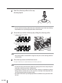
2
Adjust the roll spacer position according to the media width.
(1) Remove the two screws and move
the roll spacer to the center of the
media. There are three screwing
positions.
Roll spacer
Do not move this roll spacer.
Scroller
– The roll spacer prevents the paper tube from bending at the center due to the
media weight.
2-7
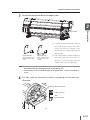
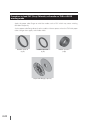
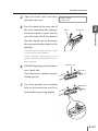
3
Insert the scroller into the paper tube, determine the distance
between the media edge and the flange, and then secure the
main scroller.
Flange
Media
(1) Check the media winding direction,
and then insert the scroller into the
paper tube.
Attach the paper setting
gauge’s flange side to
the flange’s spoke side.
Outer take-up
Inner take-up
Paper setting gauge
(2) Determine the distance between
the media edge and the flange with
the paper setting gauge.
(3) Rotate the handle clockwise as far
as it will go, and then secure the
scroller at the point.
Handle
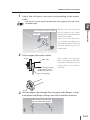
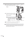
4
Attach the flange spacer and the flange stopper with the flange
stopper matching with the claw of the flange spacer.
Flange spacer
Flange stopper
Knob
2-8
(1) The flange spacer has teeth. Push it
as far as it will go.
(2) Match the flange stopper with
the claw of the flange spacer, and
then tighten the knob to secure
the flange spacer and the flange
stopper.
Media installation and removal
5
Attach the scroller by fitting it with the roll groove of the printer.
2
Basic operation
Printer rear (supply side)
Scroller
Roll groove
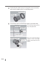
– To set the scroller alone:
Use a recommended dolly.
– To set the scroller manually by two
persons:
Use the supplied scroller handle.
Recommended dolly
Scroller
handle
Scroller
Scroller
2-9
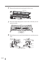
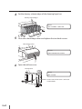
6
Remove the protection bar and open the front cover.
Front cover
Protection bar
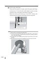
7
Move the media edge guards to each side so that they are not
under the media.
Media edge guards
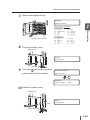
8
Rotate the pressure control knob clockwise to raise the pressure
roller.
Takeup side
Supply side
or
Pressure control knobs
2-10
Media installation and removal
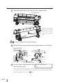
9
Insert the media end into the paper feeder while smoothing out
the media by hand to prevent wrinkles.
Paper feeder
2
Basic operation
Printer rear
- Up curl
af
rle ia
e
t
In Med
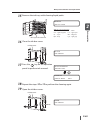
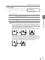
10
- Down curl
dia leaf
er
Int
Me
If it is hard to insert the media end
into the paper feeder due to a curl
of the media, interpose an interleaf
and insert the media end under the
interleaf as shown in the left figure.
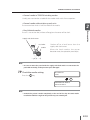
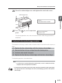
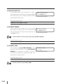
Feed the media until the media end almost reaches the floor.
In this state, smooth out the media toward the both sides on the platen to make
the media center tense.
Platen
Note
– If the media is set with a distortion or wrinkles, this may cause a media jam or
skew.
2-11
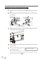
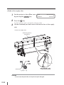
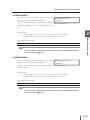
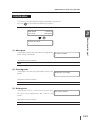
11
Feed back the media to the top of the front paper guide.
Front paper guide
Feed back the media
while pressing the
center of the media
gently at the supply
side.
– Step 11 is important to set the media properly.
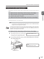
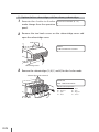
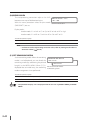
12
Rotate the pressure control knob counterclockwise to lower the
pressure roller.
Takeup side
Supply side
or
Pressure control knobs
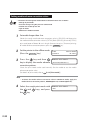
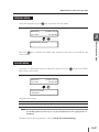
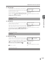
13
Set the media edge guards and
CHECK EDGE GUARD
close the front cover.
*OK?
Check that the media edge guards are not under the media or thick media is
not caught by inserting it forcibly. After confirming visually that the media edge
guards are properly set, press the
key.
2-12
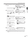
Media installation and removal
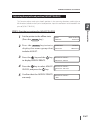
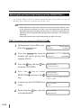
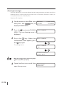
14
Select roll media or cut-sheet
SELECT MEDIA
media.
ROLL/SHEET:ROLL
ROLL/SHEET:SHEET
Either [roll] or [sheet] can be selected with the
key or
Here, select [roll] and press the
key.
(To return to the media selection, press the CANCEL key.)
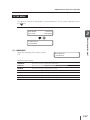
Select the type of media.
SELECT MEDIA
Select the registered type of
media with the
and
keys
MEDIA:TYPE02
and press the
key. (
[MEDIA REG MENU])
MEDIA:TYPE02
P.3-30
2
Basic operation
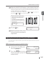
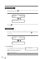
15
key.
To register new media
[NEW MEDIA ENTRY] is displayed at
the end of the registered media.
Press the
key to enter MEDIA
REG MENU.
The media registration procedure is
the same as the registration from the
registration menu.
( P.3-30 [MEDIA REG MENU])
SELECT MEDIA
MEDIA:TYPE02
MEDIA:TYPE02
(The registered media is displayed.)
SELECT MEDIA
NEW MEDIA ENTRY
Press the
key to return from
the media registration menu to the
media type selection menu.
To return to the value before input,
press the CANCE L key.
16
(Enter the media registration menu.)
Enter the remaining media.
SET REMAINING MEDIA
Enter the remaining roll media loaded on
the printer. ( P.3-28 [MEDIA MENU])
*XXXm
Note
– After installing the media, check whether the media on the platen has no float or
wrinkles.
2-13
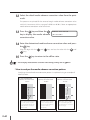
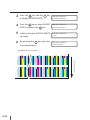
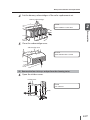
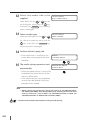
17
This sign is displayed when the
CHECK
slack is insufficient.
SLACKEN MEDIA
- In case of use of sheet media, this
message is not displayed.
- If the media slackness is insufficient, the
next operation will not be started.
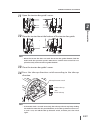
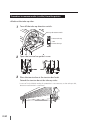
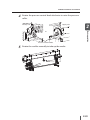
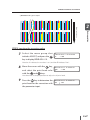
18
Press the tension bar to the peel roller’s upper part. Then create
a slack between the platen and the peel roller, by carrying the
tension bar to the rear side of the peel roller with a supply-side
feed switch (black).
Tension bar
Switch
Tension bar
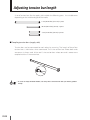
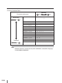
Adjust the tension bar length and decide whether to attach a flange or not,
depending on the type and width of the media.
Examples of tension bar combinations
Size used
2-14
Tension bar length
L
48 inches (123 cm)
L, S
64 inches (164 cm)
L, S, S
80 inches (204 cm)
L, M, S, S
104 inches (264 cm)
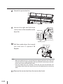
Media installation and removal
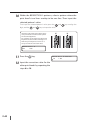
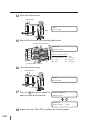
<General media in TENSION winding mode>
Usually put a tension bar suitable for the media width with a few exceptions.
<General media without take-up reel unit>
Put a tension bar which is half the width of the media.
Put an S size tension bar (without a flange) on the center of the slack.
Supply-side slack sensor
Peel roller
Scroller
Basic operation
<Vinyl chloride media>
2
Slacken off to a level lower than the
supply-side slack sensor.
When the slack reaches the sensor
detection area, the operation panel blips.
Note
– Be sure to rotate the panel with the supply-side feed switch. Do not rotate the
peel roller manually, or the printer may be damaged.
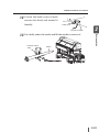
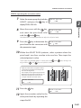
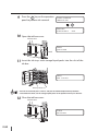
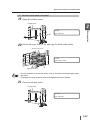
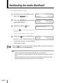
19
Check the media setting.
SET MEDIA
Press the
*OK?
key.
PREPARING MEDIA
PLEASE WAIT
Note
– Rewind the printer's media completely at the end of the day. The PVC media
installed and left for a night on the printer may cause media jam.
2-15
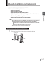
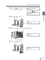
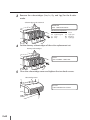
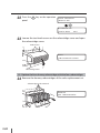
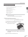
Procedure to install general roll media to the take-up reel unit
For the procedure for attaching the vinyl chloride roll media to the winding device, please
refer to "Procedure to load PVC (Vinyl Chloride) roll media on TUR in LOOSE winding
mode>" on page 2-22.
1
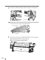
Adjust the roll spacer position according to the media width.
– The roll spacer prevents the paper tube from bending at the center due to the
media weight.
(1) Remove the two screws and move
the roll spacer to the center of the
media. There are three screwing
positions.
Roll spacer
Do not move this roll spacer.
Scroller
2
Prepare a paper tube and attach it to the scroller.
Flange
(1) Determine the distance between
the paper tube edge and the flange
using the paper setting gauge, and
secure the flange by rotating the
Attach the paper setting
handle.
Paper tube
gauge’s flange side to
the flange’s spoke side.
Paper setting gauge
Handle
2-16
Media installation and removal
3
Attach the flange spacer and the flange stopper with the flange
stopper matching with the claw of the flange spacer.
Flange spacer
(1) The flange spacer has teeth. Push it
as far as it will go.
Flange stopper
Basic operation
(2) Match the flange stopper with
the claw of the flange spacer, and
then tighten the knob to secure
the flange spacer and the flange
stopper.
2
Knob
4
Set the take-up direction switch to OFF.
Note
– If the printer processing proceeds to the next step with the take-up direction
switch set to ON, your hand may be caught as the scroller is not secured.
Take-up direction switch
Outer take-up
OFF
- OFF
Inner take-up
2-17
5
Attach the scroller by fitting it with the roll groove of the printer.
Scroller
Roll groove
Note
– Hook the tension bar to the tension bar hook beforehand.
Tension bar hook
Tension bar
6
Feed the media with the FORM FEED MENU on the operation
panel to an extent where it can be taken up.
(
2-18
P.2-97 [Feeding the media [Feed]])
Media installation and removal
7
Install the drawn media to the paper tube.
2
Tape
Inner take-up:
Outer take-up:
Media is taken up with
its print surface comes
inside.
Media is taken up with
its print surface comes
outside.
Basic operation
Paper tube
(1) Check the take-up direction, remove
the slack of the media, and then
make sure that the media is not
deviated on the supply side and the
takeup side.
(2) With tape hold the media straight at
the center, and then at the rest six
positions in the direction from the
media center to the media edge.
Note
– Be careful of the tape affixing direction on the takeup side.
– If the media is not installed straight to the paper tube, a skew of media may
occur.
8
Set the take-up direction switch according to the take-up
direction.
Take-up direction switch
Outer take-up
OFF
- OFF
Inner take-up
2-19
9
Advance the media with the FORM FEED MENU on the operation
panel to wind it around the paper tube by one turn. Then set the
take-up direction switch to OFF.
Note
– If the tension bar is attached without winding the media by one turn, the tape
will peel off.
10
Advance the media with the FORM FEED MENU on the operation
panel to an extent where a slack can be created.
Be sure to create a sufficient slack so that the tension bar is placed at the bottom
of the tension bar guide.
Printer front (takeup side)
Tension bar
Tension bar guide
2-20
Media installation and removal
11
Open the tension bar guide’s cover.
2
Place the tension bar at the bottom of the tension bar guide.
Basic operation
12
Note
– When the tension bar does not reach the tension bar guide’s bottom, feed the
media with the operation panel’s FEED menu. Confirm that tension bar was
placed securely at the tension bar guide’s bottom.
13
Close the tension bar guide’s cover.
14
Press the take-up direction switch according to the take-up
direction.
Take-up direction switch
Outer take-up
OFF
- OFF
Inner take-up
Note
– If the media slack is secured excessively, the take-up reel unit may keep winding
the media for more than the prescribed time, and a take-up timeout error occurs.
In such a case, turn off the take-up direction switch, and then press the switch
again.
2-21
Procedure to load PVC (Vinyl Chloride) roll media on TUR in LOOSE
winding mode
Apply the paper tube flange to wind the media such as PCV which may cause winding
deviation frequently.
Set the paper tube flange directly to the scroller without spacers when the TUR-side paper
tube is longer than supply-side media width.
Rubber spacer A
(1 pc)
Rubber spacer B
(1 pc)
Paper tube flange (2 pieces)
2-22
Rubber spacer C
(1 pc)
Media installation and removal
1
Adjust the roll spacer's position corresponding to the media
width.
– Roll spacer is used to prevent the paper tube from sagging in the center under
the media weight.
Roll spacer
3 positions
Scroller
2
Basic operation
Do not change this roll spacer's position.
Remove two screws fixing the
left roll spacer of the figure,
and move the roll spacer to the
center of the media.
N o te t h a t t h re e p o s i t i o n s
are available to relocate the
removed roll spacer. Select one
position depending on the
media width.
Flange
2
Set the paper tube to the scroller.
With a paper setting gauge,
adjust the distance between
the paper tube edge and the
flange, then fix it by rotating
the knob.
3
Run the paper tube through the two paper tube flanges so that
each paper tube flange's fixing screw side would face outward.
Run the paper tube through
the two paper tube flanges.
2-23
4
Confirm that the rubber spacer A is facing the correct orientation,
and crown the rubber spacer A on the flange spacer.
Rubber Spacer A
Flange spacer
5
Fix the flange spacer and the flange stopper on the paper tube.
Push the flange spacer all the
way in the paper tube.
Flange spacer
Flange stopper
Rubber Spacer A
Notches at four positions
Protrusions at
two positions
2-24
Then insert and fix the flange
stopper so that the flange
stopper's protrusions fit in the
notches.
Media installation and removal
6
Fix the rubber spacer C to the scroller.
Rubber Spacer C
2
Mount the scroller to the TUR, which will make the operation
Basic operation
7
easier from this step.
8
Unroll the media until the media can be wound with the
operation panel's FEED menu.
9
Adjust the paper tube position.
Paper tube
Flange
Media
Knob
Clear this gap.
Confirm that no gap is found
between the left edge of the
media fed at the step (8) and
the paper tube's edge.
If a gap is found, adjust
the paper tube position by
loosening the knob and clear
the gap.
Then fix the paper tube by
rotating the knob.
2-25
10
Set the paper tube flange.
Slowly pull the media out straight, and fix the paper tube flange
at the position, 3-5 mm from the media edge by evenly screwing
the three screws at the paper tube flange's outer side.
Rotate the take-up roll referring to the NOTE 1 below, and
confirm that the two paper tube flanges do not swing at all.
Paper tube flange fixing
screws at three positions
3 to 5mm gap to be secured
at the both media edges
NOTE1
– Rotate the take-up roll with the procedure below.
(a) Cover the sensor window by sliding your hand downward as shown by the
arrow of the figure below. Note that the take-up roll is rotated only with the
sensor's downstroke shielding.
(b) By keeping the sensor window covered, the take-up roll rotates for 4 seconds
and stops.
(c) When the take-up roll needs to be rotated more, repeat the steps (a) and (b).
Sensor window
2-26
Media installation and removal
NOTE2
– When the paper tube's inner diameter is not sufficiently longer than the flange
spacer's diameter, the flange spacer cannot be pushed all the way in the paper
tube, and the gap may be found between the rubber spacer A and the paper tube
edge. In such a case, to clear the gap set the rubber spacer B between the rubber
spacer A and the paper tube.
11
2
Basic operation
Rubber Spacer B
Rubber Spacer A
Attach the media to the paper tube.
Confirm that the media is wound in outer-side take-up mode. With adhesive
tape, hold the media straight at the center, and then at the rest positions in the
direction from the media center to the media edge.
NOTE
– Ensure that the media is attached with no slant nor slack which will cause
the slanting feed.
12
Feed the media with the operation panel's FEED menu, and take
up the media on the paper tube for one turn or more.
13
Check the paper tube flanges' position, and adjust it if necessary.
14
With the panel operation, set the printer to online.
2-27
Cut-sheet media installation/removal procedure
1
2
Open the front cover, and move the media edge guards to each
side.
Rotate the pressure control knob clockwise to raise the pressure
roller (Open).
Takeup side
Supply side
or
Pressure control knobs
3
Align the right end of the cut sheet with the guideline and insert
the cut sheet into the paper feeder.
4
Rotate the pressure control knob counterclockwise to lower the
pressure roller.
5
Set the media edge guards and
CHECK EDGE GUARD
close the front cover.
*OK?
Check that the media edge guards are not under the media or thick media is
not caught by inserting it forcibly. After confirming visually that the media edge
guards are properly set, press the
key.
2-28
Media installation and removal
6
Select roll media or cut-sheet
SELECT MEDIA
media.
ROLL/SHEET:ROLL
ROLL/SHEET:SHEET
Either [roll] or [sheet] can be selected with the
key or
Here, select [sheet] and press the
key.
(To return to the media selection, press the CANCEL key.)
Select the type of media.
SELECT MEDIA
Select the registered type of
media with the
and
keys
MEDIA:TYPE02
and press the
key. (
[MEDIA REG MENU])
MEDIA:TYPE02
P.3-30
2
Basic operation
7
key.
To register new media
A message "NEW MEDIA ENTRY"
is displayed at the end of the
registered media.
Press the
key to enter MEDIA
REG MENU.
The media registration procedure is
the same as the registration from the
registration menu.
( P.3-30 [MEDIA REG MENU])
Press the
key to return from
the media registration menu to the
media type selection menu.
To return to the value before input,
press the CANCE L key.
8
SELECT MEDIA
MEDIA:TYPE02
MEDIA:XXXX
(The registered media is displayed.)
SELECT MEDIA
NEW MEDIA ENTRY
(Enter the media registration menu.)
The media set operation starts
PREPARING MEDIA
automatically.
PLEASE WAIT
– When the media set operation is successfully completed, the printer returns to the
online or offline state.
– If the media set operation is not completed, an error message appears. Retry the
procedure beginning with step 1.
Note
– After installing the media, check whether the media on the platen has no float or
wrinkles.
2-29
Procedure to remove media (scroller) from the printer
<Media at the take-up side>
1
Turn off the take-up direction switch.
Take-up direction switch
Outer take-up
OFF
- OFF
Inner take-up
2
Open the tension bar guide’s cover.
3
Place the tension bar at the tension bar hook.
Detach the tension bar at the take-up sides.
In case of vinyl chloride media, this procedure is not necessary at the take-up side,
because no tension bar is used there.
2-30
Media installation and removal
4
Open the front cover, and then cut the media.
Set the cutter to the cutter groove, and
cut the media along the grove.
2
Platen
Note
– A net is spread out on the feeding side and take-up side paper guides,
respectively so that the media will not adhere to the guides.
Do not remove these nets.
– When cutting the media, be careful not to damage the paper guide net.
– Pay attention not to drop the used media so as to avoid messing up the floor.
5
6
Set the printer to the offline state
INK
by pressing the
M E D I A
Press the
ONLINE
key.
Basic operation
Paper guide
MEDIA REG
M.ADV
key.
The TUR’s take-up switch is activated by selecting media and setting the take-up
direction switch to ON.
7
Rotate the scroller the wind switch (black) at the supply side to
take up the media.
Take-up reel switch (Black)
2-31
8
Detach the protection bar.
Protection bar
9
Loosen the right and left knob
screws next to the movable media
Knob screw
dryer fan.
Media dryer fan
10
Pull the media dryer fan toward
Media dryer fan
you and turn it upward 90
degrees.
Note
– When the media dryer fan is turned upward, it slightly goes down and is fixed. To
return the fan to its original position, pull it up and turn it toward you, and then
push it and secure it with the knob screws.
– Turn the media dryer fan carefully so that the pressure control knob and
surrounding sheet metals do not get hung up on the media dryer fan connecting
cable.
11
2-32
Remove the tension bar from the tension bar hook.
Media installation and removal
12
Loosen the knob screw of each
tension bar hook and extend it
laterally.
Knob screw
Tension bar hook
Set a dolly under the media and lift the media to remove it.
Recommended
dolly
Media
Basic operation
13
2
2-33
<Media at the supply side>
1
2
Set the printer to the offline state
INK
by pressing the
M E D I A
Press the
ONLINE
key.
MEDIA REG
M.ADV
key.
The TUR’s take-up switch is activated by selecting media.
3
Lift the slackened part and remove the tension bar at the supply
side.
Printer rear (supply side)
<Media in general>
Tension bar
Peel roller
Peel roller
Scroller
Tension bar
S size tension bar
<Vinyl chloride media>
CAUTION
– Do not ratate the peel roller, or the printer may be damaged.
2-34
Media installation and removal
4
Rotate the pressure control knob clockwise to raise the pressure
roller.
Takeup side
Supply side
Pressure control knobs
5
Basic operation
or
2
Rotate the scroller manually to take up the media.
2-35
6
Remove the scroller of the printer.
Printer rear (supply side)
Scroller
Roll groove
– To set the scroller alone:
Use a recommended dolly.
– To set the scroller manually by
two persons:
Use the supplied scroller handle.
Recommended dolly
Scroller
handle
Scroller
Scroller
2-36
Media installation and removal
Procedure to remove media from the scroller
1
2
Put the media roll on the table.
Remove the flange stopper and the flange spacer.
Basic operation
3
2
Remove the scroller.
(1) Rotate the handle counterclockwise.
(2) When a gap is generated between the
handle and the scroller shaft, remove
the scroller.
Note
– Do not touch the claw of the scroller.
When no media is loaded on the scroller
1
The message appears on the LCD.
NO MEDIA LOADED
LOAD MEDIA
2
Replace media following the media installation/removal
procedure.
When replacing roll media due to jamming
Refer to [Section 5 When encounting a problem (How to clear media jams)].
2-37
Setting media advance correction values
– The factors that change the media advance correction values are as follows.
• Change of print mode
• Pressure change using the pressure control knob
• Use/not use of take-up reel unit
• Type of media
• Difference in media feed route
1
Set media longer than 4 m.
Obtain the rough media advance correction value in [ROUGH] and determine
the media advance correction value in [DETAIL]. Both [ROUGH] print and [DETAIL]
print need paper of about 90 cm in length for one-time print. (To cancel printing
of media advance correction pattern, press the CANCEL key.
2
3
Set the printer to the offline mode.
INK
(Press the
M E D I A
key.)
ONLINE
Press the
key and then
key to display the media advance
MEDIA REG
M.ADV
#MEDIA ADV PRINT
>ROUGH(NORMAL1)
correction pattern.
Select the print mode to be used normally for the media to set the media
advance correction value.
(For details of print mode, refer to
P.4-2 [Print mode].)
Note
– To obtain the media advance correction value in DENSITY2 mode, apply the
media advance correction patterns, ROUGH(QUALITY) or DETAIL(QUALITY).
4
Select the rough print mode with
the
the
2-38
and
key.
keys, and press
#MEDIA ADV PRINT
*OK?
Media installation and removal
5
Press the
key. Then the media
advance correction pattern
#MEDIA ADV PRINT
*EXECUTING
[ROUGH] is printed in the selected
print mode.
Select a rough media advance correction value from the print
result.
Nine patterns are printed with 0.5% increments within a range of 99.00% to
101.00%. Select a rough media advance correction value from them.
7
Press the
key and then the
Basic operation
6
2
#MEDIA ADV VALUE
key to display the media advance
>01:099.80%
correction value.
8
Enter the media advance correction value and press the
Align the digit with the
keys.
9
Press the
and
keys and set the value with the
key and then the
key to display the media advance
key.
and
#MEDIA ADV PRINT
>ROUGH(NORMAL1)
correction pattern.
10
Select the detail print mode with
#MEDIA ADV PRINT
the
>DETAIL(NORMAL1)
and
keys.
Select the same print mode as for [ROUGH].
11
Press the
key twice to print the
media advance correction pattern
#MEDIA ADV PRINT
*EXECUTING
[DETAIL].
2-39
12
Select the detail media advance correction value from the print
result.
Five patterns are printed for the entered rough media advance correction value
with 0.1% increments within a range of -0.20% to +0.20%. Select an appropriate
media advance correction value from them.
13
Press the
key and then the
#MEDIA ADV VALUE
key to display the media advance
>01:099.80%
correction value.
14
Enter the determined media advance correction value and press
the
key.
Align the digit with the
keys.
15
Press the
and
keys and set the value with the
and
key to return to the offline state.
– For changing media advance correction value during printing, refer to
P.3-8.
* How to analyze the media advance correction pattern
Analyzing the media advance correction pattern is explained using an example of
black (K) color.
In case of small media
advance correction value
99.00%
When observing the horizontal
lines, if the splices of paths
are overlapped (dense), the
media advance correction
value is small.
2-40
In case of appropriate media
advance correction value
100.25%
When the splices of paths
are not overlapped and
even, the media advance
correction value is
appropriate.
In case of large media
advance correction value
101.00%
When the splices of paths
are separated (light), the
media advance correction
value is large.
Media installation and removal
Adjusting the print head position [ADJUST PH POS]
This function adjusts each print head’s position in the scanning direction, media right to
left direction, based on the K print head position. Input the correction value based on the
print of [ADJUST PH POS].
1
2
Set the printer to the offline state.
INK
(Press the
M E D I A
Press the
ONLINE
M E N U
key.)
key twice to
display the menu group that
MEDIA REG
M.ADV
PRINTER
SETUP
A D J U S T
HEATER
Basic operation
STEP1 Print the test pattern for [ADJUST PH POS]
2
includes ADJUST.
3
4
Press the
key and the
#NOZZLE PRINTS
to display NOZZLE PRINTS.
* NOZZLE PRINT
Press the
#NOZZLE PRINTS
key to select ADJUST
PH POS, and press the
5
key
key.
* ADJUST PH POS
Confirm that the NOZZLE PRINTS
#NOZZLE PRINTS
are ready.
* OK?
2-41
6
By pressing the
key, print the
#NOZZLE PRINTS
* EXECUTING
test pattern below.
• [ADJUST PH POS] print sample
0
+1
-32
-31
+3
+2
-29
-30
+4
+31
-28
+31
-1
7
Select the menu group that includes
#PH TO PH VAL
ADJUST, and press the
#Y
key to
>+00
display PH TO PH VAL.
8
Move the cursor with the
key,
and select the print head color
with the
and
#PH TO PH VAL
#* L c
>+00
keys.
Here describes a sample operation to adjust the Lc print head.
9
Press the
key to determine the
print head for the correction with
the parameter input.
2-42
#PH TO PH VAL
#Y
** + 0 0
Media feed direction
STEP2 Inputting the correction value
Media installation and removal
10
Within the ADJUST PH POS patterns, select a pattern where the
reference K print head’s line and the determined print head’s line
overlap with the least misalignment.
Then input the selected pattern’s value, press the
digit, and the
and
keys to input the value.
and
#PH TO P H VA L
#Lc
11
-21
>+0 2
Press the
Lc
key.
+2
#PH TO PH VAL
#Lc
12
Lc
2
Basic operation
Input the value of the test pattern where
the K print head’s line and the determined
print head’s line overlap with the least
misalignment.
For example, on the right test patterns for
Lc print head, the two lines misalign at -21
while they overlap at +2. So input +2 for the
correction value.
keys to align the
>+02
Input the correction values for the
other print heads by repeating the
steps 6 to 10.
Adjusting the print head nozzles' R/L position [ADJUST PH R/L]
This function adjusts each print head’s right and left nozzles position, based on the print of
[ADJUST PH R/L].
STEP1 Printing the test pattern for [ADJUST PH R/L]
1
2
Set the printer to the offline state.
INK
(Press the
M E D I A
Press the
ONLINE
M E N U
key.)
key twice to
display the menu group that
MEDIA REG
M.ADV
PRINTER
SETUP
A D J U S T
HEATER
includes ADJUST.
2-43
3
4
Press the
key and the
6
#NOZZLE PRINTS
to display NOZZLE PRINTS.
* NOZZLE PRINT
Press the
#NOZZLE PRINTS
key to select ADJUST
PH R/L, and press the
5
key
* ADJUST PH R/L
key.
Confirm that the NOZZLE PRINTS
#NOZZLE PRINTS
are ready.
* OK?
By pressing the
key, print the
#NOZZLE PRINTS
* EXECUTING
test pattern below.
• [ADJUST PH R/L] print sample
0
Media feed direction
-32
+1
-31
+2
-30
+3
-29
+4
-28
+31
-32
2-44
Media installation and removal
STEP2 Inputting the correction value
7
Select the menu group that includes
# PH R/L ADJ VAL
ADJUST, and press the
#Y
key to
>+00
2
display PH R/L ADJ VAL.
Move the cursor with the
key,
and select the print head color
with the
and
Basic operation
8
#PH R/L ADJ VAL
#M
>+00
key.
Here describes a sample operation to adjust the M print head.
9
Press the
key to determine the
print head for the correction with
#PH R/L ADJ VAL
#M
* +00
the parameter input.
10
Within the ADJUST PH R/L patterns, select a pattern where the
print head’s two lines overlap to be one line. Then input the
selected pattern’s value.
Then input the selected pattern’s value, press the
digit, and the
and
keys to input the value.
#M
11
M
-21
-8
>-0 8
Press the
key.
#PH R/L ADJ VAL
#M
12
keys to align the
M
Input the value of the test pattern where
each print head’s two lines overlap with
the least misalignment.
For example, on the right test patterns for
M print head, the two lines misalign at -21
while they overlap to be one line at -8.
So input -8 for the correction value.
#PH R /L A D J VA L
and
>-08
Input the correction value for the
other print heads by repeating the
steps 6 to 10.
2-45
Adjusting the print head’s bidirectional position [BIDIRECTION]
This function adjusts each print head’s bidirectional position, based on the print of
[BIDIRECTION]. Note the indicates the number 1 to 4.
Note
– Before bidirectional adjustment, forcedly set the media heater to ON to warm
up the printer for 30 minutes or more. Start the bidirectional ink spotting
adjustment only after confirming that the printer is warmed up sufficiently. The
adjustment may not be performed correctly when the printer is not warmed up
sufficiently.
For the procedure to warm up the media heater forcedly, see P.2-102.
STEP1 Printing the test pattern for [BIDIRECTION]
1
2
Set the printer to the offline state.
INK
(Press the
M E D I A
key.)
ONLINE
Press the
M E N U
key twice to
display the menu group that
MEDIA REG
M.ADV
PRINTER
SETUP
A D J U S T
HEATER
includes ADJUST.
3
4
Press the
key and the
key
to display TEST PRINTS.
>NOZZLE PRINT
Press the
#TEST PRINTS
key to select
BIDIRECTION , and press the
6
Confirm that the TEST PRINTS are
#TEST PRINTS
ready.
* OK?
By pressing the
test pattern below.
2-46
>BIDIRECTION
Select 1, 2, 3, or 4 depending on
the print mode.
key.
5
#TEST PRINTS
key, print the
#TEST PRINTS
>EXECUTING
Media installation and removal
• [BIDIRECTION] print sample
0
Basic operation
Media feed direction
2
+1
-32
+2
-31
-30
+3
+4
-29
-28
+31
-32
STEP2 Inputting the correction value
7
Select the menu group that
# BIDIR ADJ XXXXXX
includes ADJUST, and press the
#Y
>+00
key to display BIDIR ADJ .
Note the indicates the numbers 1 to 4, and that indicates R or L.
8
Move the cursor with the
key,
and select the print head color
with the
and
#BIDIR ADJ XXXXXX
#M
>+00
keys.
Here describes a sample operation to adjust the M print head.
9
Press the
key to determine the
print head for the correction with
#BIDIR ADJ XXXXXX
#M
* +00
the parameter input.
2-47
10
Within the BIDIRECTION patterns, select a pattern where the
print head’s two lines overlap to be one line. Then input the
selected pattern’s value.
Then input the selected pattern’s value, press the
digit, and the
and
keys to input the value.
#M
M
-21
-8
> - 08
11
Press the
12
Input the correction value for the
key.
BIDIR ADJ XXXXXX
#M
other print heads by repeating the
steps 6 to 10.
2-48
keys to align the
M
Input the value of the test pattern where
each print head’s two lines overlap with
the least misalignment.
For example, on the right test patterns for
M print head, the two lines misalign at -21
while they overlap to be one line at -8.
So input -8 for the correction value.
#BIDIR ADJ and
>-08
Ink pack installation and replacement
Note
– Do not remove ink tray in the following cases. Otherwise, ink may spill in the
printer depending on the printer state, which may result in a breakdown.
2
Basic operation
This section describes [Ink pack replacement procedure].
Replace ink pack in the following three cases.
– When ink is exhausted
– When no ink pack is installed
– When changing print mode (8 colors/4 colors)
(Refer to the 8-color to 4-color mode change procedure and the 4-color to
8-color mode change procedure.)
– When the ink pack is not recognized
– When the ink charge from ink tray is not completed
• When the printer is not powered on due to power interruption or circuit breaker
off.
• When an error other than ink end error has occurred
– Do not touch the contacts in the plate of the ink pack.
Ink pack installation/replacement procedure
1
Push the knob of the ink box cover to open the ink box.
Ink box cover
Knob
2-49
2
Confirm the color of the ink pack to be replaced, and pull the ink
tray out of the printer.
Ink tray
3
Take the empty ink pack out of the ink tray.
If ink is not installed, go to step 4.
Push the two claws at the lower part of the plate of the ink pack, and pull up the
plate . Then remove the ink pack from the hook of the ink tray .
Plate
1
Ink pack
2
Push two claws
Ink tray
2-50
Hook
Ink pack installation and replacement
4
Take a new ink pack out of the box and set it in the ink tray.
Hook the two holes at the end of the ink pack on the ink tray's two protrusion.
Then insert the plate into the ink tray until a click is heard .
New ink pack
Plate
1
Protrusion
2
Basic operation
2
Ink tray
5
Insert the ink tray into the slot of the printer.
Note
– Insert the ink tray as far as it will go.
– The location of ink tray is determined by color. Be sure to insert each ink tray into
the specified slot.
Ink tray
2-51
6
Close the ink box cover.
Ink box cover
7
Confirm that the ink pack replacement was completed.
– When the replacement is successfully completed, the printer returns to the online or
offline state.
– If the replacement is not completed, an error message appears. Retry the replacement
procedure beginning with step 1.
– While ink is remaining in the subcartridge even during replacement of ink, print
operation is performed.
Replacing ink pack when ink is exhausted
1
The error message is displayed.
OPEN INK COVER
XXX REPLACE INK CART
2
Replace the specified ink pack
according to [Ink pack installation/
replacement procedure].
XXX: Ink color and position
8-color mode
Y1
Lm2
C3
Gy4
: Yellow
: Light magenta
: Cyan
: Gray
K5
Lc6
M7
Lg8
: Black
: Light cyan
: Magenta
: Light gray
K5
C6
M7
Y8
: Black
: Cyan
: Magenta
: Yellow
4-color mode
Y1
M2
C3
K4
2-52
: Yellow
: Magenta
: Cyan
: Black
Ink pack installation and replacement
Replacing ink during printing
This printer allows replacement of ink pack during online printing without interrupting
print operation. For this reason, the ink replacement guidance during online printing is
displayed cyclically in the second line of the LCD. The following shows guidance when the
ink box cover is opened during online printing and when ink in the ink pack is exhausted.
Basic operation
<When the ink box cover is opened>
2
P R I N T IN G
R O L L : 1 0 4 / PA P E R
P R I N T IN G
C LO SE
P R I N T IN G
CO VE R
The guidance message to prompt you to close the ink box cover appears in the second
line of the LCD.
While ink is remaining in the subcartridge even when the ink box cover is open, print
operation is continued. However, no ink is supplied to the subcartridge because the ink
box cover is open.
When the ink in the subcartridge is exhausted, the printer enters the print pause mode
and print operation is interrupted until the ink box cover is closed. To restart the operation
from this print pause mode, close the ink box cover and press the O N L I N E key. The print
pause mode is reset and print operation is restarted.
2-53
<When ink in the ink pack is exhausted>
PRINTING
ROLL:104/PAPER
PRINTING
XXX: INK COLORS
OPEN COVER
PRINTING
XXX REPLACE INK CART
The guidance message to prompt you to replace the ink pack appears in the second line
of the LCD.
Print operation is continued until the ink in the subcartridge is exhausted. When the ink
pack has been replaced before the ink in the subcartridge is exhausted, the printer can
continue to print without interruption.
If the ink pack has not been replaced before the ink in the subcartridge is exhausted, the
printer enters the print pause mode and print operation is interrupted until the ink pack is
replaced. To restart the operation from this print pause mode, close the ink box cover and
press the O N L I N E key. The print pause mode is reset and print operation is restarted.
– The ink replacement guidance during online printing is displayed cyclically in the
second line of the LCD in the same way as the first case. Restoring the operation in
each case is enabled by the same operation as for normal error processing.
2-54
Ink pack installation and replacement
When no ink pack is installed
1
The guidance message is displayed.
XXX LOAD
INK PACK
Install the specified ink pack
XXX: Ink color and position
8-color mode
according to [Ink pack installation/
Y1
Lm2
C3
Gy4
replacement procedure].
: Yellow
: Light magenta
: Cyan
: Gray
2
K5
Lc6
M7
Lg8
: Black
: Light cyan
: Magenta
: Light gray
K5
C6
M7
Y8
: Black
: Cyan
: Magenta
: Yellow
4-color mode
Y1
M2
C3
K4
: Yellow
: Magenta
: Cyan
: Black
Basic operation
2
Service clean
1
2
Execute the STORE INK SYS from
#INK SYSTEM OPT
the operation panel.
>STORE INK SYS
Loosen the two knob screws on the subcartridge cover and open
the subcartridge cover.
Knob screws
OPEN
SUBCARTRIDGE COVER
Subcartridge cover
2-55
3
Remove the eight subcartridges.
Subcartridges to be removed
REMOVE SUBCARTRIDGE
4
Set the dummy subcartridges of the storage liquid set.
Dummy subcartridges
LOAD
XXX DUMMY SUBCART
XXX: Ink color and position
8-color mode
Y1
Lm2
C3
Gy4
: Yellow
: Light magenta
: Cyan
: Gray
K5
Lc6
M7
Lg8
: Black
: Light cyan
: Magenta
: Light gray
K5
C6
M7
Y8
: Black
: Cyan
: Magenta
: Yellow
4-color mode
Y1
M2
C3
K4
5
: Yellow
: Magenta
: Cyan
: Black
Close the subcartridge cover and tighten the two knob screws.
Subcartridge cover
CLOSE
SUBCARTRIDGE COVER
2-56
Ink pack installation and replacement
6
Open the ink box cover.
Ink box cover
OPEN
2
INK COVER
7
On the LCD, ink box cover is indicated
as INK COVER.
Remove the eight ink trays.
Basic operation
Knob
REMOVE
XXX INK PACK
XXX: Ink color and position
8-color mode
Y1
Lm2
C3
Gy4
Ink trays to be removed
8
: Yellow
: Light magenta
: Cyan
: Gray
K5
Lc6
M7
Lg8
: Black
: Light cyan
: Magenta
: Light gray
K5
C6
M7
Y8
: Black
: Cyan
: Magenta
: Yellow
4-color mode
Y1
M2
C3
K4
: Yellow
: Magenta
: Cyan
: Black
Close the ink box cover.
Ink box cover
CLOSE
INK COVER
2-57
9
Press the
key on the operation
panel to perform ink removal.
START PURGING
*BOTTLE OK?
PURGING
PLEASE WAIT
10
XXX
Open the ink box cover.
Ink box cover
OPEN
INK COVER
Knob
11
Insert the ink trays with storage liquid packs into the slot of the
ink box.
LOAD
XXX SL PACK
Ink trays to be set
– For how to install ink packs, refer to "Ink pack installation/replacement procedure."
– To facilitate this work, set the storage liquid packs to the optional ink trays in advance.
12
Close the ink box cover.
Ink box cover
CLOSE
INK COVER
2-58
Ink pack installation and replacement
13
Press the
key on the operation
panel to perform cleaning.
START SL CHARGING
*BOTTLE OK?
CHARGING SL
PLEASE WAIT
2
Basic operation
14
XXX
Open the ink box cover.
Ink box cover
OPEN
INK COVER
Knob
15
Remove the ink trays with cleaning liquid packs.
REMOVE
XXX SL PACK
Ink trays to be removed
16
Close the ink box cover.
Ink box cover
CLOSE
INK COVER
2-59
17
Press the
key on the operation
panel to perform ink removal.
START PURGING
*BOTTLE OK?
PURGING
PLEASE WAIT
18
XXX
Open the ink box cover.
Ink box cover
OPEN
INK COVER
Knob
19
Insert the ink trays with storage liquid packs into the slot of the
ink box.
LOAD
XXX SL PACK
Ink trays to be set
20
Close the ink box cover.
Ink box cover
CLOSE
INK COVER
2-60
Ink pack installation and replacement
21
Press the
key on the operation
panel to perform cleaning.
START SL CHARGING
*BOTTLE OK?
CHARGING SL
PLEASE WAIT
XXX
1
2
Execute the CLEAN INK SYS from
#INK SYSTEM OPT
the operation panel.
*CLEAN INK SYS
Basic operation
Head wash
2
Loosen the two knob screws on the subcartridge cover and open
the subcartridge cover.
Knob screws
OPEN
SUBCARTRIDGE COVER
Subcartridge cover
3
Remove the eight subcartridges.
Subcartridges to be removed
REMOVE
XXX SUBCARTRIDGE
2-61
4
Set the dummy subcartridges of the cleaning liquid set.
Dummy subcartridges
LOAD
XXX DUMMY SUBCART
5
Close the subcartridge cover and tighten the two knob screws.
Subcartridge cover
CLOSE
SUBCARTRIDGE COVER
6
Open the ink box cover.
Ink box cover
OPEN
INK COVER
Knob On the LCD, ink box cover is indicated
as INK COVER.
2-62
Ink pack installation and replacement
7
Remove the eight ink trays.
REMOVE
XXX INK PACK
2
XXX: Ink color and position
8-color mode
: Yellow
: Light magenta
: Cyan
: Gray
K5
Lc6
M7
Lg8
: Black
: Light cyan
: Magenta
: Light gray
K5
C6
M7
Y8
: Black
: Cyan
: Magenta
: Yellow
4-color mode
Ink trays to be removed
8
Y1
M2
C3
K4
: Yellow
: Magenta
: Cyan
: Black
Basic operation
Y1
Lm2
C3
Gy4
Close the ink box cover.
Ink box cover
CLOSE
INK COVER
9
Press the
key on the operation
panel to perform ink removal.
START PURGING
*BOTTLE OK?
PURGING
PLEASE WAIT
10
XXX
Open the ink box cover.
Ink box cover
OPEN
Knob
INK COVER
2-63
11
Insert the ink trays with cleaning liquid packs into the slot of the
ink box.
LOAD
XXX CL PACK
Ink trays to be set
– For how to install ink packs, refer to "Ink pack installation/replacement procedure."
– To facilitate this work, set the cleaning liquid packs to the optional ink trays in advance.
12
Close the ink box cover.
Ink box cover
CLOSE
INK COVER
13
Press the
key on the operation
panel to perform cleaning.
START CL CHARGING
*BOTTLE OK?
CHARGING CL
PLEASE WAIT
14
Open the ink box cover.
Ink box cover
OPEN
Knob
2-64
INK COVER
XXX
Ink pack installation and replacement
15
Remove the ink trays with cleaning liquid packs.
REMOVE
XXX CL PACK
2
: Black
: Light cyan
: Magenta
: Light gray
Ink trays to be removed
16
Close the ink box cover.
Basic operation
XXX: Ink color and position
Y1 : Yellow
K5
Lm2 : Light magenta Lc6
C3 : Cyan
M7
Gy4 : Gray
Lg8
Ink box cover
CLOSE
INK COVER
17
Press the
key on the operation
panel to perform ink removal.
START PURGING
*BOTTLE OK?
PURGING
PLEASE WAIT
XXX
18
Repeat the steps 10 to 13 to perform the cleaning again.
19
Open the ink box cover.
Ink box cover
OPEN
INK COVER
Knob
2-65
20
Remove the ink trays with cleaning liquid packs.
REMOVE
XXX CL PACK
Ink trays to be removed
21
Close the ink box cover.
Ink box cover
CLOSE
INK COVER
22
Press the
key on the operation
panel to perform ink removal.
START PURGING
*BOTTLE OK?
PURGING
PLEASE WAIT
2-66
XXX
Ink pack installation and replacement
8-color to 4-color mode change procedure
The procedure to change 8-color mode to 4-color mode is classified into four actions as
follow.
(1) Replace the four subcartridges with four dummy subcartridges.
(2) Remove the four ink trays and perform the cleaning twice.
(4) Replace the four dummy subcartridges with the four subcartridges.
The detailed procedure is described below.
Basic operation
(3) Set the 4-color mode's ink packs.
2
Note
– If 8-color data is received during the 4-color mode, an error is notified at the host
computer side. Print operation is disabled.
– To change the color mode to the 4-color mode, purchase the optional color replacement
set. If you do not have two subcartridges for each color (Y/M/C/K), purchase the
additional subcartridges from your dealer.
(1) Replace the four subcartridges with four dummy subcartridges.
1
2
Execute the 8-color to 4-color mode
#COLOR CHANGE (8->4)
change from the operation panel.
>
Loosen the two knob screws on the subcartridge cover and open
the subcartridge cover.
Knob screws
OPEN
SUBCARTRIDGE COVER
Subcartridge cover
2-67
3
Remove the subcartridges (Lm, Lc, Gy, and Lgy) for the 8-color
mode.
Subcartridges to be removed
REMOVE
XXX SUBCARTRIDGE
XXX: Ink color and position
Y1 : Yellow
K5
Lm2 : Light magenta Lc6
C3 : Cyan
M7
Gy4 : Gray
Lg8
4
: Black
: Light cyan
: Magenta
: Light gray
Set the dummy subcartridges of the color replacement set.
Dummy subcartridges
LOAD
XXX DUMMY SUBCART
5
Close the subcartridge cover and tighten the two knob screws.
Subcartridge cover
CLOSE
SUBCARTRIDGE COVER
2-68
Ink pack installation and replacement
(2) Remove the four ink trays and perform the cleaning twice.
6
Open the ink box cover.
Ink box cover
OPEN
INK COVER
7
On the LCD, ink box cover is indicated
as INK COVER.
Basic operation
Knob
2
Remove the ink trays (Lm, Lc, Gy, and Lgy) for the 8-color mode.
Ink trays to be removed
REMOVE
XXX INK PACK
Ink trays to be removed
8
Close the ink box cover.
Ink box cover
CLOSE
INK COVER
2-69
9
Press the
key on the operation
panel to perform ink removal.
START PURGING
*BOTTLE OK?
PURGING
PLEASE WAIT
10
XXX
Open the ink box cover.
Ink box cover
OPEN
Knob
11
INK COVER
Insert the ink trays with cleaning liquid packs into the slots of the
ink box.
Ink trays to be set
LOAD
XXX CL PACK
XXX: Ink color and position
Y1 : Yellow
K5
Lm2 : Light magenta Lc6
C3 : Cyan
M7
Gy4 : Gray
Lg8
: Black
: Light cyan
: Magenta
: Light gray
Ink trays to be set
– For how to install ink packs, refer to "Ink pack installation/replacement procedure."
– To facilitate this work, set the cleaning liquid packs to the optional ink trays in advance.
2-70
Ink pack installation and replacement
12
Close the ink box cover.
Ink box cover
2
CLOSE
INK COVER
Press the
key on the operation
START CL CHARGING
Basic operation
13
*BOTTLE OK?
panel to perform cleaning.
CHARGING INK
PLEASE WAIT
14
XXX
Open the ink box cover.
Ink box cover
OPEN
Knob
15
INK COVER
Remove the ink trays with cleaning liquid packs.
Ink trays to be removed
REMOVE
XXX CL PACK
Ink trays to be removed
2-71
16
Close the ink box cover.
Ink box cover
CLOSE
INK COVER
17
Press the
key on the operation
panel to perform ink removal.
START PURGING
*BOTTLE OK?
PURGING
PLEASE WAIT
18
Repeat the steps 10 to 17 to perform the cleaning again.
(3) Set the 4-color mode's ink packs.
19
Open the ink box cover.
Ink box cover
OPEN
INK COVER
Knob
2-72
XXX
Ink pack installation and replacement
20
Set the ink packs (Y, M, C, and K) for the 4-color mode.
Ink trays to be set
2
LOAD
Basic operation
XXX INK PACK
Ink trays to be set
– For procedure to install ink packs, refer to "Ink pack installation/replacement
procedure."
– To facilitate this work, set the ink packs to the optional ink trays in advance.
21
Close the ink box cover.
Ink box cover
CLOSE INK COVER
22
Press the
key on the operation
panel to charge ink of four colors.
START INK FILLING
*BOTTLE OK?
CHARGING INK
PLEASE WAIT
XXX
2-73
(4) Replace the four dummy subcartridges with the four subcartridges.
23
Loosen the two knob screws on the subcartridge cover and open
the subcartridge cover.
Knob screws
OPEN
SUBCARTRIDGE COVER
Subcartridge cover
24
Remove the dummy subcartridges of the color replacement set.
Subcartridges to be removed
REMOVE
XXX SUBCARTRIDGE
25
Set the four subcartridges (Y, M, C, and K) for 4-color mode.
Dummy subcartridges
LOAD
XXX DUMMY SUBCART
2-74
Ink pack installation and replacement
26
Close the subcartridge cover and tighten the two knob screws.
Subcartridge cover
CLOSE
27
Press the
key on the operation
panel.
Basic operation
SUBCARTRIDGE COVER
2
START CLEANING
*BOTTLE OK?
The cleaning operation starts and the 8-color to 4-color mode change procedure is
completed.
4-color to 8-color mode change procedure
The procedure to change 4-color mode to 8-color mode is classified into four actions as
follow.
(1) Replace the four subcartridges with four dummy subcartridges.
(2) Remove the four ink trays and perform the cleaning twice.
(3) Set the 8-color mode's ink packs.
(4) Replace the four dummy subcartridges with the four subcartridges.
The detailed procedure is described below.
Note
– If 4-color data is received during the 8-color mode, an error is notified at the host
computer side. Print operation is disabled.
– To change the color mode to the 8-color mode, purchase the optional color replacement
set. If you do not have subcartridges for colors (Lm/Lc/Gy/Lgy), purchase the optional
subcartridges.
2-75
(1) Replace the four subcartridges with four dummy subcartridges.
1
Execute the 4-color to 8-color
#COLOR CHANGE (4->8)
mode change from the operation
>
panel.
2
Remove the two knob screws on the subcartridge cover and
open the subcartridge cover.
Knob screws
OPEN
SUBCARTRIDGE COVER
Subcartridge cover
3
Remove the subcartridges (Y, M, C, and K) for the 4-color mode.
Subcartridges to be removed
REMOVE
XXX SUBCARTRIDGE
XXX: Ink color and position
Y1
M2
C3
K4
2-76
: Yellow
: Magenta
: Cyan
: Black
K5
C6
M7
Y8
: Black
: Cyan
: Magenta
: Yellow
Ink pack installation and replacement
4
Set the dummy subcartridges of the color replacement set.
Dummy subcartridges
LOAD
XXX DUMMY SUBCART
2
Basic operation
5
Close the subcartridge cover.
Subcartridge cover
CLOSE
SUBCARTRIDGE COVER
(2) Remove the four ink trays and perform the cleaning twice.
6
Open the ink box cover.
Ink box cover
OPEN
INK COVER
Knob
2-77
7
Remove the ink trays (Y, M, C, and K) for the 4-color mode.
Ink trays to be removed
REMOVE
XXX INK PACK
XXX: Ink color and position
Y1
M2
C3
K4
: Yellow
: Magenta
: Cyan
: Black
K5
C6
M7
Y8
: Black
: Cyan
: Magenta
: Yellow
Ink trays to be removed
8
Close the ink box cover.
Ink box cover
CLOSE
INK COVER
9
Press the
key on the operation
panel to perform ink removal.
START PURGING
*BOTTLE OK?
PURGING
PLEASE WAIT
10
Open the ink box cover.
Ink box cover
OPEN
INK COVER
Knob
2-78
XXX
Ink pack installation and replacement
11
Insert the ink trays with cleaning liquid packs into the slots of the
ink box.
Ink trays to be set
2
Basic operation
LOAD
XXX CL PACK
Ink trays to be set
– For how to install ink packs, refer to "Ink pack installation/replacement procedure."
– To facilitate this work, set the ink packs to the optional ink trays in advance.
12
Close the ink box cover.
Ink box cover
CLOSE
INK COVER
13
Press the
key on the operation
panel to perform cleaning.
START INK CHARGING
*BOTTLE OK?
CHARGING INK
PLEASE WAIT
XXX
2-79
14
Open the ink box cover.
Ink box cover
OPEN
INK COVER
Knob
15
Remove the ink trays with cleaning liquid packs.
Ink trays to be removed
REMOVE
XXX CL PACK
XXX: Ink color and position
Y1 : Yellow
K5
Lm2 : Light magenta
Lc6
C3 : Cyan
M7
Gy4 : Gray
Lg8
: Black
: Light cyan
: Magenta
: Light gray
Ink trays to be removed
16
Close the ink box cover.
Ink box cover
CLOSE
INK COVER
17
Press the
key on the operation
panel to perform ink removal.
START PURGING
*BOTTLE OK?
PURGING
PLEASE WAIT
18
2-80
XXX
Repeat the steps 10 to 17 to perform the cleaning again.
Ink pack installation and replacement
(3) Set the 8-color mode's ink packs.
19
Open the ink box cover.
Ink box cover
2
INK COVER
Knob
20
Basic operation
OPEN
Set the ink trays (Lm, Lc, Gy, and Lgy) for the 8-color mode.
Ink trays to be set
LOAD
XXX INK PACK
Ink trays to be set
– For the procedure to install ink packs, refer to "Ink pack installation/replacement
procedure."
– To facilitate this work, set the ink packs to the optional ink trays in advance.
21
Close the ink box cover.
Ink box cover
CLOSE
INK COVER
2-81
22
Press the
key on the operation
panel.
START CHARGING
*BOTTLE OK?
CHARGING INK
PLEASE WAIT
23
XXX
Loosen the two knob screws on the subcartridge cover and open
the subcartridge cover.
Knob screws
OPEN
SUBCARTRIDGE COVER
Subcartridge cover
(4) Replace the four dummy subcartridges with the four subcartridges.
24
Remove the dummy subcartridges of the color replacement set.
Subcartridges to be removed
REMOVE
XXX SUBCARTRIDGE
2-82
Ink pack installation and replacement
25
Set the four subcartridges (Lm, Lc, Gy, and Lgy) for 8-color mode.
Subcartridges
LOAD
2
XXX DUMMY SUBCART
Close the subcartridge cover and tighten the two knob screws.
Basic operation
26
Subcartridge cover
CLOSE
SUBCARTRIDGE COVER
27
Press the
panel.
key on the operation
START CLEANING
*BOTTLE OK?
The cleaning operation starts and the 4-color to 8-color mode change procedure is
completed.
2-83
When the ink pack is not recognized
1
2
With the guidance message confirm
CHECK
the unrecognized ink pack.
XXX INK PACK
Reinstall the ink pack according to
[Ink pack installation/replacement
procedure].
nn
XXX: Ink color and position
8-color mode
Y1
Lm2
C3
Gy4
: Yellow
: Light magenta
: Cyan
: Gray
K5
Lc6
M7
Lg8
: Black
: Light cyan
: Magenta
: Light gray
K5
C6
M7
Y8
: Black
: Cyan
: Magenta
: Yellow
4-color mode
Y1
M2
C3
K4
: Yellow
: Magenta
: Cyan
: Black
nn: Error code
Note
– Unrecognized ink pack cannot be used.
– If the guidance message is still displayed after the ink pack is reinstalled, contact
our service depot.
When the ink charge from ink tray is not completed
When the massage prompting ink supply is diplayed before printing or print head's
cleaning, prepare an ink pack and operate as follow.
<Ink supply>
1
2
The massage prompting ink
#INK SUPPLY
supply is displayed.
>
Press the
#INK SUPPLY
key.
>
3
Press the
key.
#INK SUPPLY
*OK?
2-84
Ink pack installation and replacement
4
Open the ink box cover.
Ink box cover
2
OPEN
Basic operation
INK COVER
Knob
5
Remove the ink trays with dummy packs.
Ink trays to be removed
REMOVE
XXX DUMMY INK PACK
XXX: Ink color and position
8-color mode
Y1
Lm2
C3
Gy4
: Yellow
: Light magenta
: Cyan
: Gray
K5
Lc6
M7
Lg8
: Black
: Light cyan
: Magenta
: Light gray
K5
C6
M7
Y8
: Black
: Cyan
: Magenta
: Yellow
4-color mode
Ink trays to be removed
6
Y1
M2
C3
K4
: Yellow
: Magenta
: Cyan
: Black
Set the ink trays.
Ink trays to be set
LOAD
XXX INK PACK
Ink trays to be set
2-85
7
Close the ink box cover.
Ink box cover
CLOSE
INK COVER
8
Press the
key.
#INK SUPPLY
*OK?
#INK SUPPLY
*EXECUTING
#INK SUPPLY
>
2-86
Waste ink bottle installation and replacement
This section describes the waste ink bottle replacement procedure.
Replace the waste ink bottle in the following two cases.
– When no waste ink bottle is installed
– When the waste ink bottle becomes full
The treatment procedure for each case is shown below.
2
Note
Basic operation
– Do not replace the waste ink bottle during printing.
Waste ink bottle installation procedure
1
Confirm that the printer recognizes
BOTTLE OUT
no waste ink bottle with the
INSTALL BOTTLE
guidance message.
2
Install a new waste ink bottle.
Refer to [Procedure when the waste ink bottle becomes full].
Note
– Before using the printer, check visually whether the waste ink bottle is full. When
the waste ink bottle is full, treat it following [Procedure when the waste ink bottle
becomes full].
3
Confirm the message to select the
#BOTTLE EMPTY?
waste ink counter reset (clear) is
*NO
displayed.
,
#BOTTLE EMPTY?
*YES
Note
– The waste ink counter counts the amount of waste ink and is used to display a
message prompting you to replace the waste ink bottle with a new one when
it becomes full. The count of waste ink volume is assumptive, and therefore the
waste ink bottle full state cannot be accurately detected. Basically, the counter
works on the premise that it is cleared when an empty waste ink bottle is
installed. Therefore, always select "#BOTTLE EMPTY? *YES" with a new waste ink
bottle installed. If this premise is ignored, the waste ink bottle full detect counter
does not function correctly and waste ink will become full before the waste ink
bottle full alarm is generated, which may cause the waste ink to overflow.
4
Select "BOTTLE EMPTY? *YES" and press the
key.
2-87
Procedure when the waste ink bottle becomes full
Note
– Replace the waste ink bottle carefully not to bump your head on the printer
upper part.
1
Slide the lever up and lift the whole cap.
Tube
Lever
Waste ink bottle
2
The ink drips from the tube. Leave it for a while.
3
Remove the full waste ink bottle from the unit paying attention
not to spill the waste ink. Then cap it and replace it with a new one.
4
Wipe off the spill ink in the waste ink bottle unit.
5
Slide the lever up and install a new waste ink bottle.
6
Lower the lever.
Tube
Lever
Waste ink bottle
Note
– Do not hit the external cover's upper part, or the waste ink may spill.
2-88
Waste ink bottle installation and replacement
7
The message to select the
#BOTTLE EMPTY?
waste ink counter reset (clear) is
*NO
displayed.
,
2
#BOTTLE EMPTY?
*YES
Select "BOTTLE EMPTY? *YES" and press the
Basic operation
8
key.
Procedure when no waste ink bottle is installed
1
Confirm that the printer recognizes
BOTTLE OUT
no waste ink bottle with the
INSTALL BOTTLE
guidance message is displayed.
2
Install a new waste ink bottle.
Refer to [Procedure when the waste ink bottle becomes full].
3
Confirm the message to select the
#BOTTLE EMPTY?
waste ink counter reset (clear) is
*NO
displayed.
,
#BOTTLE EMPTY?
*YES
4
Select "BOTTLE EMPTY? *YES" and press the
key.
2-89
Replacing the wiper blade
The following describes the wiper blade replacement procedure.
Replace the wiper blade when the replacement message appears or scratches are found
in the daily inspection. Prepare the tweezers supplied in the daily maintenance kit before
replacing the wiper blade.
1
Set the printer to the offline state
REWIND
and press the
P H . R E C
M E N U
key to
FORM FEED
PH.MAIN
display PH.MAIN MENU.
2
Press the
key to enter PH.MAIN
MENU. The cap cleaning menu is
#CAP CLEANING
>
displayed.
3
Select [REPLACE WIPER BLADE]
#REPLACE WIPER BLADE
with the
>
key and press the
key.
4
5
6
When the confirmation screen
#REPLACE WIPER BLADE
appears, press the
*OK?
key.
Open the front cover and wipe
OPEN COVER
cover.
REPLACE WIPER BLADE
Nip the bottom edge of the wiper
blade with tweezers and release the
hook of the plastic projection.
7
2-90
Remove the wiper blade upward.
Replacing the wiper blade
8
Nip the rubber of the new wiper blade with the tweezers and
insert it straight downward, and install it by hooking the hole in
the rubber to the plastic projection.
2
Basic operation
Rubber part
Note
– When handling the wiper blade, do not
touch its upper part by hand or nip it with
tweezers because the upper part directly
contacts with the print head.
9
10
Upper part
Close the wipe cover and front
#REPLACE FINISHED
cover.
*NO
Select [* YES] and press the
#REPLACE FINISHED
key to finish the replacement.
*YES
Note
– The printer automatically adds up the usage time period of the wiper blade and
displays a message prompting you to replace the wiper blade. On the premise
that a new wiper blade is installed and [*YES] is set, the accumulator calculates
the usage time period. (When [*YES] is set, the value of accumulator is reset.) If
this premise is ignored, the time for replacement is erroneously detected.
– Replace the all eight wiper blades at a time. If they are replaced partially, a wrong
replacement message may appear.
2-91
Correcting the edge sensor position
Print out the edge sensor adjustment pattern, and correct the edge sensor position.
After printing, measure the distance and specify the parameter.
1
2
Hold down the
M E N U
key until
PRINTER
SETUP
the [ADJUST] menu appears.
A D J U S T
HEATER
Press the
#TEST PRINTS
key to enter the
>NOZZLE PRINT
[ADJUST] menu.
3
Press the
4
Hold down the
key.
key until the
[CHECK EDGE SENSOR] menu
#TEST PRINTS
>CHECK EDGE SENSOR
appears.
5
Press the
key.
#TEST PRINTS
*OK?
6
Press the
key.
#TEST PRINTS
*EXECUTING
7
Judge the printing results.
Measure the margin of the printing result
with a square, and obtain an difference
between the measured margin and the
value (15 mm) shown in the specifications.
508 nozzles
(Blank by the even
number of heads)
15 mm
If the difference is 15 mm, complate this
procedure.
If not, follow the prcedure below to correct
the value.
2-92
508 nozzles
(All nozzles)
Replacing the wiper blade
8
Press the
key to enter the
>±Y.Ymm
[ADJUST] menu.
9
Press the
#EDGE SENSOR ADJ VAL
key to display the
2
[EDGE SENSOR ADJ VAL] menu,
10
key.
Based on the printed sensor
#EDGE SENSOR ADJ VAL
adjustment pattern, enter the
>±Y.Ymm
correction value of the edge
Basic operation
and press the
sensor position.
11
Press the
key to decide the
entered value.
12
Press the
#EDGE SENSOR ADJ VAL
>+0.0mm
key to return to the
higher-level menu.
To obtain the correction value:
Obtain the correction value by measuring the margin setting the reference value
to 15 mm.
<Example>
The margin is 14 mm: The correction value is -1.0 mm.
The margin is 16 mm: The correction value is +1.0 mm.
2-93
Adjusting tension bar length
A set of tension bars for the supply side includes the following parts. Use suitable ones
depending on the width and type of the media.
L size (48 inches) (123 cm): 1 piece
M size (24 inches) (61 cm): 1 piece
S size (16 inches) (41 cm): 2 pieces
Coupling tension bars (supply side)
Tension bars can be connected to each other by screwing. The length of these four
tension bars is 104 inches when connected. The L-size tension bar whose both ends
are convex is always used. M-size and S-size tension bars whose one end is concave are
coupled with the L-size tension bar.
– In case of vinyl chloride media, use only one S size tension bar (16 inches) (about
41cm).
2-94
Print head cleaning
The following two types of print head cleaning are provided. Use the suitable one.
Type of cleaning
Usage
NORMAL ALL
Recovery from nozzle-out
STRONG ALL
Recovery from nozzle-out that is not rectified by [NORMAL ALL]
1
2
Set the printer to the offline state.
INK
(Press the
M E D I A
Press the
ONLINE
M E N U
key.)
key to display
INK
M E D I A
PH.REC MENU.
MEDIA REG
M.ADV
Basic operation
Print head cleaning procedure
2
MEDIA REG
M.ADV
M E N U
REWIND
P H . R E C
3
Press the
key to enter the head
FORM FEED
PH.MAIN
#PH RECOVERY
>NORMAL
cleaning menu.
Note
– If ink filling from the ink tray is not yet completed, the ink supply menu is
displayed instead of the cleaning menu. (
P.2-84)
– Prepare an ink pack and perform ink supply operation.
4
5
To change the parameter, press
#PH RECOVERY
the
>NORMAL
key.
Select the option for cleaning
#PH RECOVERY
with the
>NORMAL
and
keys.
>STRONG
2-95
6
Press the
key.
#PH RECOVERY
*BOTTLE OK?
7
Select head numbers with the
#SELECT: 8 7 6 5 4 3 2 1 F B
key or the
*BOTTLE OK?
key, and reverse
(display or non-display) the
selected head numbers with the
key or the
key.
Note
– The indicated head numbers denote the heads to be cleaned.
8
Press the
key.
#PH REC XXXXXXXX
*BOTTLE OK?
XXX: Selected head numbers
9
Check visually that the waste ink
#PH RECOVERY
bottle is not full and press the
*CLEANING
key once again.
XXX
XXX: This value is counted down every 10
seconds.
Note
– Print head cleaning takes several minutes.
– When the cleaning starts, the required time is displayed and the time is counted
down every 10 seconds.
10
Upon completion of the print head
#PH RECOVERY
cleaning, the cleaning process returns
>NORMAL
to step 3 .
11
Press the
key to return to the
offline state (menu mode).
2-96
REWIND
P H . R E C
FORM FEED
PH.MAIN
Feeding the media [Feed]
This function feeds the media.
1
INK
(Press the
M E D I A
Press the
ONLINE
M E N U
key.)
key to display
the menu group that includes
REWIND
P H . R E C
MEDIA REG
M.ADV
FORM FEED
PH.MAIN
FORM FEED MENU.
3
Keep pressing the
While the
fed.
4
key.
FEEDING MEDIA
2
Basic operation
2
Set the printer to the offline state.
key is pressed, the media is
When the
key is released, the
printer stops feeding the media
REWIND
P H . R E C
FORM FEED
PH.MAIN
and returns to the offline state
(menu mode).
– When the
key is pressed in the online state (idle mode), the printer can feed media
without entering the FORM FEED MENU.
2-97
Backfeeding the media [Backfeed]
This function backfeeds the media.
1
2
Set the printer to the offline state.
INK
(Press the
ONLINE
M E D I A
Press the
M E N U
key.)
key to display
Keep pressing the
M.ADV
FORM FEED
P H . R E C
the REWIND MENU.
3
REWIND
MEDIA REG
key.
PH.MAIN
REWINDING MEDIA
While the
key is pressed, roll media is
fed back.
When cut-sheet media is used, it is ejected.
4
When the
key is released, the
printer stops backfeeding the
REWIND
P H . R E C
FORM FEED
PH.MAIN
media and returns to the offline
state (menu mode).
– When the
key is pressed in the online state (idle mode), the printer can backfeed
media without entering the REWIND MENU.
Note
– Apply the roll feed unit to backfeed media only for a short distance.
For a long distance, carefully apply it so that the media slack would not reach the
floor.
Besides note that the take-up reel unit does not perform the backfeed operation.
Do not backfeed media with the take-up reel unit’s operation.
2-98
Nest function
<Nest function>
The nest function is a function to re-set the origin of print. For example, when printing a
small image of A4 size is printed on the media of 64-inch width, a large margin is created as
shown below. In such a case, by rewinding the printed media and re-setting the print start
origin, the margin can be effectively used for printing.
(First print)
(Rewinding of media)
(Second print)
2
Basic operation
Margin
Set the print start origin
Note
– Complete this operation as immediately as possible. Or perform the cleaning as
the print heads dry and the print image quality is affected.
<Nest function>
1
Return the media by operating [Back Feed].
(
P.2-98 Backfeeding the media [Backfeed])
Note
– Rewind the media after the printed image completely dries. If this function is
used while the media is not sufficiently dry, printed image obtained during the
first printing will be damaged.
2
Keep pressing the
key for 1.5
seconds in the online state (idle
NEST ORIGIN SETTING
*OK?
mode), the carriage moves and the
nest function becomes available.
Align the mark at the lower left of the
front panel of the carriage with the origin.
Origin
2-99
3
While "NEST ORIGIN SETTING"
NEST ORIGIN SETTING
is displayed, move the carriage
CARRIAGE MOVING
with the
and
keys to the
position to be set as an origin.
4
Press the
key to fix the nest
NEST ORIGIN SETTING
origin setting.
*OK?
The carriage returns and the printer enters
the online state (idle mode) and becomes
ready to print.
NEST ORIGIN SETTING
PLEASE WAIT
PRINTER READY
NEST:1625/PAPER
To cancel the set origin, keep pressing the
key for 1.5 seconds in the idle mode or
raise the pressure control knob. When the
origin is cancelled, the display returns from
[NEST] to [ROLL].
2-100
<Display when cancelled>
PRINTER READY
ROLL:1625/PAPER
Changing temperature using the heater control menu
The heater initial value that is set with MEDIA REG MENU is automatically set for the
temperature of each heater. Therefore, the heater control menu is not needed normally.
The heater control menu is used to fine-adjust the heater temperature during printing or
to monitor the current heater temperature.
2
Heater control menu display
HEATER
key to display the heater control menu.
(Centigrade temperature display)
Print heater information
Afterheater information Preheater information
A f t 40
C)
40
P r n 45
P r e
45
Set temperature
C)
45
Current temperature
C)+40
Basic operation
Press the
The "+" mark shows heating.
(Fahrenheit temperature display)
Shows heater off.
A f t 104 P r n OFF P r e 113
F)
104
F) 110
F)
113
2-101
Key operation in the heater control menu
and
keys Select a heater for which temperature is to be set.
and
keys Set the heater temperature.
M E N U
key
Selects heater ON or OFF.
When this key is pressed for 1.5 seconds while the heater control menu
is displayed, all the heaters are forcibly turned on even without print
operation. (The heating control starts.)
key
Pressing this key for 1.5 seconds with the heater control menu displayed
CANCEL
key
cancels the heater-on state made forcibly by the
key. (The heating
control stops.)
To finish displaying the heater control menu
Press the
HEATER
key while the heater control menu is displayed.
– Even if heater temperature is changed in the heater control menu, the initial temperature
value of each heater stored in MEDIA REG MENU remains unchanged.
– When the temperature unit in SETUP MENU is set to Fahrenheit, every temperature is
displayed in Fahrenheit.
When the heater control menu display finishes automatically
HEATER DISPLAY END
If there is no key input for 30 seconds while the heater control menu is displayed, a
message "HEATER DISPLAY END" appears automatically for two seconds and then the
heater control menu display finishes. While this message is displayed, no key input is
disabled.
2-102
Changing temperature using the heater control menu
Reference information on media types and heater settings
The heater set temperatures and reference set values (initial values) of print mode for each
type of media are shown in the table below. Change the settings for use according to the
media in use.
Recommended heater temperature setting
Media
selection
Afterheater
Printheater
Preheater
Glossy vinyl
chloride
Glossy
45ºC
40ºC
45ºC
Normal 8-path
bidirectional
Matte vinyl
chloride
Matte
45ºC
40ºC
45ºC
Normal 8-path
bidirectional
Banner
Banner
45ºC
40ºC
45ºC
Normal 8-path
bidirectional
Print mode
2
Basic operation
Media type
It is recommended that temperature of the afterheater, print heater, and preheater be set
to less than 50°C, 45°C, and 50°C respectively.
Note
– Setting a high temperature for the print heater makes ink fusion better, but
may cause wrinkles in the media or matte of the print surface. Adjust the heater
temperature according to the media type and ambient temperature.
– When the print heater is set to a high temperature, the printer lowers the printing
speed automatically in some cases to maintain stable print quality.
– Set the afterheater and preheater temperatures so that they are nearly +5°C
higher than the print heater temperature. Bad temperature balance between
afterheater/preheater and print heater may cause wrinkles in the media.
– Setting a high temperature for the print heater may cause nozzle-out.
Heater temperature setting procedure
(1) When a media type is selected in media setting, initial temperature values of each
heater for the selected media type are displayed on the menu.
(
P.2-101 [Heater control menu display])
When the initial temperature value is set, the heater is turned on.
(Heating does not start until print starts.)
When the initial temperature value is set to [**], the heater is turned off.
(The heater set temperature is not displayed.)
(2) When print data is received from the host Computer, either of the following is
performed before printing.
– The set temperature on the heater control menu is overwritten by the
temperature that is set by the RIP (print data, job), and heating starts.
– When no temperature is set by the RIP (print data, job), heating starts
with the set temperature on the heater control menu.
2-103
(3) When the current temperature of the afterheater, print heater, and the preheater
reaches the temperature that is 1°C lower than the set temperature, the printer starts
printing.
When the current temperature is higher than the set temperature, the printer
starts printing before the temperature lowers. The temperature control is
performed continuously after printing starts because these heaters keep their set
temperature.
(4) The heater temperature varies during printing by changing the set temperature
with the heater control menu. Even after printing is completed, the set temperature
changed in the heater control menu remains as "set temperature." However, the initial
temperature value of each heater stored in MEDIA REG MENU remains unchanged.
(5) The subsequent printing returns to (2).
– The three heaters work in the state displayed on the LCD regardless of the means to set
their temperatures.
– The following figure shows the heater temperature control system for printing. The
standby time can be changed with the heater menu in the offline mode. (
menu])
(Temperature)
Print
Standby time
Print heater set temperature
Preheater set temperature
Afterheater set temperature
Standby set temperature
Ambient temperature
(Time)
Set temperature
maintained
2-104
Standby temperature
maintained
Temperature
control stop
P.3-62 [Heater
How to use the pressure control knob
How to use the pressure control knob
2
Basic operation
The pressure control knob is used to adjust the media pressing force of the media feeding
grid roller according to the media to be used.
Set the pressure control knob properly according to the media. The pressure force can be
adjusted to "low," "normal" or "high." The pressure control knob has four positions: "high,"
"normal," "low," and "open" used when installing media. It can be turned both clockwise
and counterclockwise.
The pressure control knob is provided on the supply side and takeup side. The pressure
force can be adjusted on the supply side or takeup side because operation of the two
pressure control knobs is interlocked.
Pressure control knobs
Open ⇔ Low ⇔ Normal ⇔ High
Takeup side
Supply side
– Basically set the pressure force to “normal,” at this setting most of the media provide a
good-accuracy print. Set the pressure force to “low,” when printing on the flexible media
such as fabric banner.
2-105
How to use the head up/down mechanism
The printer automatically adjusts the head height to the best height when the printer is
turned on or when media is set. To adjust the head height according to the media to be
used, select MEDIA REG MENU on the operation panel and adjust the head height.
Note
– Adjust the head height so that the head does not contact with the media. Friction
of the head may cause poor firing of the head and degrade the print quality. On
the other hand, excessive head height from the media will also degrade the print
quality. Use the printer with the head height that is automatically adjusted by the
printer.
1
2
Set the printer to the offline state.
INK
Press the
M E D I A
ONLINE
Press the
key.
key to display the
>01:TYPE01
MEDIA REG MENU.
3
Press the
key and then
or
key to display [PH HEIGHT VAL].
4
Press the
key, and enter the
head height adjustment value with
the
or
key.
The adjustment value range is: -0.3 to +1.0
mm.
5
Press the
key to determine the
adjustment value.
2-106
#SELECT MEDIA
#PH HEIGHT VAL
>01:+0.0mm
#PH HEIGHT VAL
>01:+1.0mm
MEDIA REG
M.ADV
How to use media edge guards
To protect the print head from warp and feathering at both ends of media, use media
edge guards in the media feed path and slide it to meet the media width.
(Wiping station side)
(Capping station side)
2
Basic operation
Media edge guards
[Media edge guard specifications]
– Capable of media thickness of up to 1 mm.
– Decreases the print area.
– Reduces the effect of the suction fan.
Note
– Make the media edge guard usage setting in the MEDIA REG MENU from the
operation panel. The right and left margins of the media are controlled by this
setting.
– When media edge guards are used, the right and left print area margins increase
to 10 mm. (When no media edge guard is used, the margins are 5 mm.)
– When the media edge guard is stained, wipe it out.
– Remove feathering that cannot be removed by the media edge guard beforehand
as it may cause nozzle-out.
2-107
Periodic maintenance
This section describes periodic inspection and maintenance of the printer.
Periodic inspection/maintenance guide
This printer needs to be periodically inspected and maintained. The following table lists
periodic inspection/maintenance items. Perform each inspection/maintenance item
referring to the pages shown in the table.
Classification
1
Daily inspection and maintenance
Inspection and maintenance
Check the wiper blade for contamination
2-109
Replenish wiper cleaning liquid
2-110
Clean the capping unit
2-111
Replenishing spittoon absorber liquid
2-113
Check the waste ink bottle
2-113
Clean the carriage
2-114
Clean the media edge guard
2-117
Performing normal cleaning
2-117
Performing nozzle print
2-117
Cleaning the print head
2-118
Replacement of the spittoon case
2-118
Service clean
2-121
2
Bimonthly inspection and maintenance
3
Maintenance conducted when leaving
the printer in the power-off state for
more than two weeks
Maintenance conducted when
operating the printer after power-off
for more than two weeks
Head wash
2-122
4
Charging ink after head wash
2-123
Maintenance conducted when
operating the printer after power-off
for less than two weeks
Head wash
2-124
Charging ink after head wash
2-125
Maintenance conducted when the
printer has been left in the power-off
state for more than one month
The service call error is displayed. Contact the
sales dealer or our nearest service depot.
2-125
5
6
For details of operation, refer to Section 3.
2-108
Reference
page
Periodic maintenance
Daily inspection and maintenance
2
Basic operation
To maintain stable print quality, carry out the following nine items everyday.
(1) Check the wiper blade for contamination.
(2) Replenish wiper cleaning liquid.
(3) Clean the capping unit.
(4) Replenish the spittoon absorber liquid.
(5) Check the waste ink bottle.
(6) Clean the carriage.
(7) Clean the media edge guard.
(8) Perform normal cleaning.
(9) Perform nozzle print.
Note
– Carry out these items everyday.
– Be sure to use the cleaning liquid and cleaning swabs specified by us.
< Checking the wiper blade for contamination>
Visually check the wiper blade for contamination and scratches.
If the wiper blade is scratched, replace it. ( P.2-90 [Replacing the wiper blade])
1
2
Open the front cover, and then open the wipe cover.
Visually check the wiper blade for
Wiper blade
contamination and scratches.
Wiper blade
Note
– Check the level of the remaining wiper cleaning liquid. If small amount of wiper
cleaning liquid is remaining, replenish it. (
P.2-110 [Replenishing wiper
cleaning liquid])
3
Close the wipe cover and the front cover.
2-109
<Replenishing wiper cleaning liquid>
When the remaining wiper cleaning liquid becomes little, replenish it.
1
Open the front cover, and then open the wipe cover.
2
Visually check the wiper
Liquid level
cleaning liquid level through
the cleaning liquid port at the
lower right of the top face of the
wipe unit.
Cleaning liquid port
If the liquid lever is below the top of the
"" mark that can be seen inside the
cleaning liquid port, replenish wiper
cleaning liquid to a level below the top
Wiper cleaning liquid
of the "" mark.
3
2-110
Close the wipe cover and the front cover.
Periodic maintenance
<Cleaning the capping unit>
1
Attach the cleaning roller to the
2
1
cleaning stick.
Set the printer to the offline state
INK
and press the
M E D I A
M E N U
key to
MEDIA REG
display PH.MAIN MENU.
3
Press the
key to enter PH.MAIN
MENU. The cap cleaning menu is
M.ADV
Basic operation
2
2
#CAP CLEANING
>
displayed.
4
Press the
key. When the
confirmation screen appears, press
the
#CAP CLEANING
>
key again.
The carriage moves.
#CAP CLEANING
*OK?
CARRIAGE MOVING
PLEASE WAIT
– When the carriage moves, the warning beeps.
( P.3-59 [(5) BEEP (cap open)])
5
Open the front cover and then
OPEN COVER
open the cap cover.
CLEAN CAP
2-111
6
Soak the cleaning roller in the cap
cleaning liquid.
Note
– Do not soak the cleaning roller that once cleaned the cap in the cap cleaning
liquid bottle. The cap cleaning liquid will be contaminated.
7
Clean the top surface of the cap by rolling the cleaning roller.
1.
Roll the roller back and forth
on each cap.
2.
Then roll the roller back and
forth 10 times on each cap.
Note
– The cleaning roller is intended for a single use only. Use a new cleaning roller for
each cleaning.
8
Close the cap cover and the front cover.
The print head returns automatically to the home position.
Note
– Do not leave the print head away from the capping unit unnecessarily. The print
head dries, which may result in a malfunction.
– If nozzle-out still occurs even after the above cleaning is performed, remove
foreign matters and ink stains on the cap with a cleaning swab dampened with
cap cleaning liquid while checking visually.
– Be careful so that the cap cleaning liquid does not adhere to any part other than
the cap.
2-112
Periodic maintenance
<Replenishing spittoon absorber liquid>
1
Open the front cover, and then open the cap cover.
2
Check the spittoon absorber
2
liquid level in the spittoon unit
If the liquid level has become so
low that the boss for liquid quantity
measurement is visible, refill the spittoon
absorber liquid up to the same level as
the top of the boss.
Liquid level
Spittoon unit
Basic operation
visually.
top of the boss
If the spittoon absorber liquid should be
replaced,
P.2-118 “Replacement of
the spittoon case”.
3
Close the cap cover and the front cover.
<Checking the waste ink bottle>
Check whether the waste ink bottle is full. When
it is full, dispose of the waste ink in an appropriate
container to clear out the waste ink bottle.
2-113
<Cleaning the carriage>
Some lint soaked with ink may be adhered to the head guard and at the both sides of the
head top section. Perform cleaning to remove such lint frequently. Remove it carefully as
it may contaminate the surface of prints.
Wipe dust off the platen.
1
Set the printer to the offline state
REWIND
and press the
P H . R E C
M E N U
key to
FORM FEED
display PH.MAIN MENU.
2
Press the
key to enter PH.MAIN
MENU. The cap cleaning menu is
#CAP CLEANING
>
displayed.
3
Press the
key. When the
confirmation screen appears, press
the
#CAP CLEANING
>
key again.
The carriage moves.
#CAP CLEANING
*OK?
CARRIAGE MOVING
PLEASE WAIT
– When the carriage moves, the warning beeps.
( P.3-59 [(5) BEEP (cap open)])
4
2-114
Open the front cover and then
OPEN COVER
open the cap cover.
CLEAN CAP
PH.MAIN
Periodic maintenance
5
Remove the knob screw of the
Spittoon unit
spittoon unit and remove the
spittoon unit.
2
Note
– The spittoon unit contains cleaning liquid. Be careful not to spill it.
6
Basic operation
Knob screw
Soak the cleaning stick in the cap
cleaning liquid.
Note
– Do not soak the cleaning stick that you used for cleaning in the cap cleaning
liquid bottle. The cap cleaning liquid will be contaminated.
7
Move the carriage manually to the
Carriage
position where the spittoon unit
was detached, and clean the right
and left sides of the top section
of the eight heads below the
carriage, using a cleaning stick.
<Head top section>
Dirt (gray parts)
Nozzle surface
2-115
Note
– Do not rub the head nozzle surface with the cleaning stick. It may cause a failure.
– The cleaning roller is intended for a single use only. Use a new cleaning roller for
each cleaning.
8
Clean the head guard at the both
sides of the carriage using the
Head guard
(gray parts)
Carriage
cleaning stick.
9
Move the carriage manually onto
Spittoon unit
the platen (left side) and secure
the spittoon unit with the knob
screw.
Knob screw
10
Close the cap cover and then close the front cover.
The carriage returns automatically to the home position.
Note
– Do not leave the carriage away from the capping unit. Finish the procedure above
within five minutes and cap the print head. Or the print head dries, which may
result in a malfunction.
2-116
Periodic maintenance
<Cleaning the madia edge guard>
Note
– Perform the procedure below withe gloves on.
Open the front cover.
Dip a cleaning swab in the
cap cleaning liquid. Checking
visually, scrub stains on the
media edge guard.
3
2
Basic operation
1
2
Clean the stains with a soft and
clean cloth.
4
Close the front cover.
<Performing normal cleaning>
Select PH.REC MENU from the operation panel, and select NORMAL ALL for cleaning.
<Performing nozzle print>
Select ADJUST MENU from the operation panel, and select TEST PRINTS to perform the
nozzle print.
Check for nozzle-out and incorrect print. The nozzle print is also used to check the print
head before the first print everyday or after the head is moved out of the capping unit for
cap cleaning. If nozzle-out is found in the nozzle print, perform the normal cleaning.
Note
– Do not leave the print head outside the capping unit. Finish the nozzle print
within five minutes and cap the print head. After the nozzle print is completed,
perform normal cleaning for the print head.
2-117
Bimonthly inspection and maintenance
<Cleaning print head with head cleaning kit>
Clean the print head almost every two months folloing the instruction supplied with the
head cleaning kit.
<Replacement of the spittoon case>
Replace the spittoon case normally once in a month. Exchange the spittoon absorber
liquid at the same time.
1
Set the printer to the offline state
REWIND
and press the
P H . R E C
M E N U
key to
FORM FEED
display PH.MAIN MENU.
2
Press the
key to enter PH.MAIN
MENU. The cap cleaning menu is
#CAP CLEANING
>
displayed.
3
Press the
key. When the
confirmation screen appears, press
the
#CAP CLEANING
>
key again.
The carriage moves.
#CAP CLEANING
*OK?
CARRIAGE MOVING
PLEASE WAIT
– When the carriage moves, the warning beeps.
( P.3-59 [(5) BEEP (cap open)])
2-118
PH.MAIN
Periodic maintenance
4
5
Open the front cover and then
OPEN COVER
open the cap cover.
CLEAN CAP
Press the knob at the near side of
the case containing the spittoon
Knob
2
Basic operation
absorber liquid to open the lid,
Discharge
raise the front side of the spittoon
absorber liquid case to discharge
the spittoon absorber liquid to the
backside.
The discharged spittoon absorber liquid
will go into the waste ink bottle.
When discharge is completed, put the
spittoon absorber liquid case back into the
original position.
6
Hold the finger grip at the spittoon
Spittoon case
case’s both side.
Then remove the spittoon case by
sliding upward.
7
Set a new spittoon case’s locating
hole to the protrusion, and fix it
horizontally by pressing slightly.
2-119
8
Moisten the spittoon case with the
Spittoon case
Dropper
spittoon absorber liquid using a
dropper.
9
Confirm that the spittoon absorber
liquid’s top surface is as high as
the top of the boss.
NOTE
– In the spittoon case, the spittoon
absorber liquid is absorbed by the
sponge, which may lower the liquid’s
top surface.
In such a case apply the liquid
additionally.
10
Liquid level
Spittoon unit
Top of the boss
Close the cap cover and then close the front cover.
The carriage returns automatically to the home position.
Note
– Do not leave the carriage away from the capping unit unnecessarily. Finish the
procedure above within five minutes, and cap the print head. Or the print head
dries, which may result in a malfunction.
2-120
Periodic maintenance
Maintenance conducted when leaving the printer in the power-off
state for more than two weeks
<Service clean> (
P.2-55)
Select PH.MAIN MENU from the operation panel, and then select the service clean.
2
Basic operation
Clean the print head and the ink flow path with the storage liquid, and leave the printer
with storage liquid filled. Eight storage liquid packs and eight dummy subcartridges are
necessary for this maintenance. Prepare the storage liquid kit (
P.1-10). The storage
liquid kit contains eight storage liquid packs and eight dummy subcartridges. Use the
eight storage liquid packs completely in a single service clean.
#INK SYSTEM OPT
>STORE INK SYS
After the service clean is completed, turn off the power of the printer with the storage
liquid cartridges inserted, and then leave the printer. To restart the printer after the service
clean and leaving, the head wash described on the following page is necessary.
2-121
Maintenance conducted when operating the printer after power-off for
more than two weeks
Clean the print head and the ink flow path with the cleaning liquid. Eight cleaning liquid
packs and eight dummy subcartridges are necessary for this maintenance. Prepare the
cleaning liquid kit (
P.1-10). The cleaning liquid kit contains eight cleaning liquid packs
and eight dummy subcartridges. Use the eight cleaning liquid packs completely in a single
head wash.
<Head wash> (
P.2-61)
Select PH.MAIN MENU from the operation panel, and then select the head wash.
#INK SYSTEM OPT
>CLEAN INK SYS
After the head wash, perform the CHARGE (INKPACK) to prime the ink system.
Note
– To keep the print head in good condition, the printer performs the fillcap
operation automatically 72 hours after the printer enters the standby state, and
then every 3 days. The printer power should be kept on for the fillcap operation
except when the printer is not used for a long time period. To protect the print
head, do not leave the printer for more than one month with no ink charged.
– Do not open or close the rear cover or lever during the service clean and head
wash. Otherwise, the operation may have to be restarted from the beginning
while wasting the ink and the cleaning liquid.
2-122
Periodic maintenance
<Charging ink after head wash>
To use the printer again after it is left for a certain period without printing, perform head
wash and then charge ink in the printer.
For the head wash, refer to P.2-61
For the ink filling, refer to P.2-84
Select PH.MAIN MENU from the operation panel, and then select CHAGE (INKPACK).
>CHARGE(>INKPACK)
Insert ink trays and charge ink.
After charging the ink, leave the printer for at least one hour. Carry out daily inspection and
maintenance, and then perform the nozzle print. If nozzle-out is found in the nozzle print,
perform [NORMAL ALL] from PH.REC MENU.
Basic operation
#INK SYSTEM OPT
2
Note
– If an ink pack containing little ink is set, a message prompting you to replace the
ink pack appears. Set an ink pack containing more than 30% ink.
2-123
Maintenance conducted when operating the printer after power-off for
less than two weeks
Clean the print head and the ink flow path with the cleaning liquid. Eight cleaning liquid
packs and eight dummy subcartridges are necessary for this maintenance. Prepare the
cleaning liquid kit (
P.1-10). The cleaning liquid kit contains eight cleaning liquid packs
and eight dummy subcartridges. Use the eight cleaning liquid packs completely in a single
head wash.
<Head wash> (
P.2-61)
Select PH.MAIN MENU from the operation panel, and the select the head wash.
#INK SYSTEM OPT
>CLEAN INK SYS
After the head wash, perform CHAGE (INKPACK) to prime the ink system.
Note
– To keep the print head in good condition, the printer performs the fillcap
operation automatically 72 hours after the printer enters the standby state, and
then every 3 days. The printer power should be kept on for the fillcap operation
except when the printer is not used for a long time period. To protect the print
head, do not leave the printer for more than one month with no ink charged.
– Do not open or close the rear cover or lever during the service clean and head
wash. Otherwise, the operation may have to be restarted from the beginning
while wasting the ink and the cleaning liquid.
2-124
Periodic maintenance
<Charging ink after head wash>
To use the printer again after it is left for a certain period without printing, perform head
wash and then charge ink in the printer.
For the head wash, refer to P.2-61.
For the ink filling, refer to P.2-84.
Select PH.MAIN MENU from the operation panel, and then select CHAGE (INKPACK).
>CHARGE(>INKPACK)
Insert ink trays and charge ink.
After charging the ink, leave the printer for at least one hour. Check the wiper cleaning
liquid amount. If the remaining is getting low, result it. Then perform the nozzle print. If
nozzle-out is found in the nozzle print, perform [NORMAL ALL] from PH.REC MENU.
(
P.3-49)
Basic operation
#INK SYSTEM OPT
2
Note
– If an ink pack containing little ink is set, a message prompting you to replace the
ink pack appears. Set an ink pack containing more than 30% ink.
Maintenance conducted when the printer has been left in the poweroff state for more than one month
The service call error is displayed regardless of whether service clean has been performed or
not. Contact the sales dealer or our nearest service depot.
Note
– To protect the print head, do not leave the printer in the power-off state for more
than two weeks with no storage liquid charged.
– When leaving the printer for more than one month, contact the sales dealer or
our nearest service depot beforehand.
2-125
Cleaning
Clean the exterior
If the printer exterior is contaminated, moisten a soft cloth with water or water-diluted
neutral detergent, wring it, and clean the exterior with the wrung cloth.
Note
– Before cleaning the printer exterior, be sure to turn off the Printer and Heater
power supply switches.
– Never use volatile solvent such as thinner and benzene. The coating may come off
or discolored.
Clean the front cover and front paper guide
If the printer is contaminated with dust and paper dust, remove them using a vacuum
cleaner. If the contamination is heavy, wipe it out with a soft cloth moistened with neutral
detergent.
Front cover
Front paper guide
Note
– Before cleaning the front cover and rear paper guide, be sure to turn off the
Printer and Heater power switches and the heater power switch.
– Do not blow off dust and paper dust as they may degrade print quality.
Carriage cleaning
Vacuum the dust off the carriage's fresh air inlet. Monthly cleaning is recommended.
Fresh air inlet
Carriage
2-126
3
Menu of operation panel
This section describes the basic menu operation on the
operation panel, structure of the operation panel, and
operation in each menu.
(Content of this section)
LCD display and state of the printer .......................................3-2
Online operation ................................................................................3-6
Basic menu operation in offline mode...............................3-12
Explanation of each menu operation .................................3-27
LCD display and state of the printer
This section describes how to read LCD display and state of the printer.
How to read LCD display
(1) Initialization state display
This display shows that the initialization is in
progress at the startup of the printer.
– When the printer starts up normally, the
printer automatically enters the online idle
mode.
Booting up...
INITIALIZING...
PLEASE WAIT
(2) Online state (idle mode) display
This display shows that the printer is ready to
receive data from the computer. (The ONLINE LED
is ON.)
PRINTER READY
ROLL: 1625 / PAPER
Media name:PAPER
– When the
key is pressed in the idle
Media of 1625 mm (64 inches) width
Roll media is set
mode, the printer can go to PH.REC MENU.
– For the display of media width, either meter
unit system or inch unit system can be
selected by the setting of [Length Unit] (
P.3-58) of the system menu.
(3) Online state (printing mode) display
This display shows that the printer is printing data.
PRINTING
ROLL: 1625 / PAPER
(4) Online state (scan standby) display
This display shows that the scan of the print head
is in the standby state for reasons such as data
printing, warmup or waiting for data transfer.
3-2
RESTING
ROLL: 1625 / PAPER
LCD display and state of the printer
(5) Online state (print pause mode) display
This display shows print pause state.
When pausing during printing
When canceling printing during pause
When resuming printing after pause
PRINTING
P R I N T E R PAU S E D
P R I N T E R PAU S E D
R O L L : 1 6 2 5 / PA P E R
R O L L : 1 6 2 5 / PA P E R
R O L L : 1 6 2 5 / PA P E R
ONLINE
The ONLINE LED blinks.
The ONLINE LED blinks.
CANCEL
ONLINE
P R I N T E R PAU S I N G
P L E A S E WA I T
PRINTING
P L E A S E WA I T
R O L L : 1 6 2 5 / PA P E R
The ONLINE LED lights.
P R I N T E R PAU S E D
R O L L : 1 6 2 5 / PA P E R
The ONLINE LED blinks.
P R I N T E R R E A DY
R O L L : 1 6 2 5 / PA P E R
The ONLINE LED lights.
– The print head can be cleaned by pressing the
ONLINE LED blinking).
key in the print pause mode (the
3
Menu of operation panel
CANCELING
(6) Online state (preheating) display
This display shows that the preheater and printheater
are being heated to the set temperature.
PREHEATING
ROLL: 1625 / PAPER
3-3
(7) Online state (print information mode) display
This display shows media traveling distance, remaining ink, and remaining media.
P R I N T E R R E A DY
Every 3 seconds interval
MENU
or
R O L L : 1 6 2 5 / PA P E R
MENU
C3
INK LEVEL : XXX%
Gy4 INK LEVEL : XXX%
MEDIA USED:
Every 3 seconds interval
MENU
or
XXXXXXm
XXXXXXXX ft
K5
Every 3 seconds interval
MENU
or
Y1
INK LEVEL : XXX%
Lc6 INK LEVEL : XXX%
Every 3 seconds interval
MENU
or
INK LEVEL : XXX%
Lm2 INK LEVEL : XXX%
M7
INK LEVEL : XXX%
Lg8 INK LEVEL : XXX%
Every 3 seconds interval
MENU
or
REMAINING MEDIA
XXXm
XXXXft
After this, the display returns to the online state.
Note
– When remaining ink is lacking, a message “YYY INK LEVEL:LOW” appears.
The following messages appear when daily maintenance is not performed or when the life
and the replacement time of consumables are drawing near.
When daily maintenance is not
performed as usual
PERFORM DAILY
MAINTENANCE NOW
M E N U
XXX: Preventive maintenance parts
(
P.5-14[When the warning
message is displayed])
3-4
REPLACE
XXX
After this, the display returns to the online
state.
LCD display and state of the printer
(8) Offline state (menu mode) display
This display shows that menu operation is enabled
in the offline state.
(
P.3-12 [Basic menu operation in offline
mode])
– , , , and denote the access key to each
menu.
– When the
key is pressed in the menu
mode display, the display changes to PH.REC
MENU.
INK
MEDIA REG
M E D I A
M.ADV
M E N U
REWIND
FORM FEED
P H . R E C
M E N U
SETUP
A D J U S T
HEATER
SHUTTING DOWN
PLEASE WAIT
3
Menu of operation panel
PRINTER
(9) Shutdown state display
This display shows that the shutdown process of
the printer is in progress.
PH.MAIN
3-5
Online operation
Operation panel keys enabled in online mode.
Condition/
mode name
Idle mode
Go to offline state
ONLINE
Disabled
Online state
Printing mode
After one scan, stop
printing and go to
pause mode
Disabled
Panel key
CAN CE L
M E N U
Display print
information
Display print
information
Go to offline cleaning Disabled
Feed media backward
with key or forward
with key
Go to media advance
correction value
operation
Pause mode
Cancel print pause
mode and go to
printing mode
Stop printing and
return to idle mode
The printer stops printing.
PRINTING
ROLL:104 / PAPER
ONLINE
PRINTER PAUSED
ROLL:104 / PAPER
The ONLINE LED blinks.
3-6
(1)
(6)
Display print
information
(4)
Go to cleaning
execution mode
(2)
Disabled
Go to shutdown mode Go to shutdown mode Go to shutdown mode
and power off
and power off
and power off
(1) Transition to the print pause mode
Explanation
(3)
(7)
Online operation
(2) Cleaning during printing
The cleaning operation is performed during online printing using the following procedure.
PRINTING
ROLL:104 / PAPER
ONLINE
PRINTER PAUSED
Press the
key in the pause mode.
# PH RECOVERY
>NORMAL
2
Select “NORMAL ALL” and “STRONG ALL” with the
press the
key.
and
keys, and
#PH RECOVERY
Menu of operation panel
1
3
The ONLINE LED blinks.
ROLL:104 / PAPER
* NORMAL
3
Check the waste ink bottle and press the
key.
#PH RECOVERY
*BOTTLE OK?
4
Press the
key. When the
CANCEL
key is pressed, the printer returns to
the pause mode.
#PH RECOVERY
* CLEANING
5
XXX
XXX: Counted down every 10 seconds.
After the cleaning is completed, the printer returns to the first state of the
pause mode.
PRINTER PAUSED
ROLL:104 / PAPER
3-7
(3) Changing media advance correction value during online printing
During online printing, the media advance correction value can be changed in the
following procedure.
1
Press the
or
key while “PRINTING” is displayed.
PRINTING
ROLL:104 / PAPER
2
The printer starts receiving data.
The Data LED blinks.
The media advance correction value that is currently active is displayed.
Change the value with the
MEDIA ADV:099.80%
* 0.99.80%
Settable range: 97.00% to 106.00%
or
key.
The value at the start of printing is displayed at the right
of the first line on the LCD and remains unchanged until
printing is finished. However, if cleaning is performed during
cleaning mode 2, the value changed halfway is displayed
after cleaning.
– The value is incremented or decremented by 0.01%
with the
or
key.
– When the value is changed, it is reflected in printing
immediately.
– The changed value is registered and retained.
– If there is no key operation for three seconds, the
display returns to the previous state.
3-8
Online operation
(4) Online state (print information mode) display
When the M E N U key is pressed during the idle mode, online printing or print pause
mode, media traveling distance and remaining ink are displayed.
PRINTER READY
PRINTING
ROLL:104 / PAPER
ROLL:104 / PAPER
M E N U
3
MEDIA USED:
XXXXXXm
Y1
INK LEVEL : XXX%
Lm2 INK LEVEL : XXX%
Every 3 seconds interval or
M E N U
C3 INK LEVEL : XXX%
Menu of operation panel
M E N U
Gy4 INK LEVEL : XXX%
Every 3 seconds interval or
M E N U
K5 INK LEVEL : XXX%
Lc6 INK LEVEL : XXX%
Every 3 seconds interval or
M E N U
M7 INK LEVEL : XXX%
Lg8 INK LEVEL : XXX%
Every 3 seconds interval or
M E N U
REMAINING MEDIA
X X X m XXXft
After that, the printer returns to the online state.
3-9
(5) Checking skew during printing
The printer checks media skew at every 3m printing. If the printer detects a skew
exceeding the specified level, the printer enters the print pause mode and displays the
screen to select continuing or stopping printing.
PRINTING
ROLL:104 / PAPER
(Perform skew check.)
When skew is detected
The ONLINE LED blinks. (Pause state)
MEDIA MISALIGNED
OK/CANCEL
Continue printing with the
key.
Stop printing with the
CANCEL key.
PRINTING
RELEASE MEDIA
ROLL:104 / PAPER
RELOAD MEDIA
(6) Cancelling printing
To cancel printing, press the
CANCEL
PRINTER PAUSED
ROLL:104 / PAPER
The ONLINE LED blinks.
CANCEL
CANCELING
PLEASE WAIT
PRINTER READY
ROLL:104 / PAPER
3-10
key in the pause mode.
Online operation
(7) Shutdown
When the power ON/OFF switch is pressed during the idle mode, online printing or print
pause mode, the printer performs the shutdown processing.
SHUTTING DOWN
PLEASE WAIT
There are following two shutdown methods.
To turn off the printer without fillcap operation
The printer is turned off without fillcap operation by pressing the power switch for 2 to
3 seconds while pressing the CANCEL key. Use this shutdown method for temporary
power-off to recover from an error or host communication error.
2
To turn off the printer with fillcap operation
The printer is turned off after fillcap operation by pressing the power switch on the
operation panel for 2 to 3 seconds.
Menu of operation panel
1
3
For details, refer to [Section 2 Power ON/OFF procedure].
3-11
Basic menu operation in offline mode
When the O N L I N E key is pressed in idle online mode, the printer enters offline mode
and the menu group is displayed on the LCD allowing menu operation.
INK
MEDIA REG
MEDIA
M.ADV
M E N U
REWIND
FORM FEED
PH.REC
PH.MAIN
M E N U
#PH RECOVERY
>NORMAL
When the
key is pressed in any menu
group, the PH.REC MENU screen opens.
PRINTER
ADJUST
SETUP
HEATER
M E N U
Note
– When the O N L I N E key is pressed even if an error is being displayed, the printer
enters offline mode. However, the printer may not become offline depending on
error type or while an error is being processed. In this case, rectify the error and
then set the printer to the offline state.
3-12
Basic menu operation in offline mode
Menu layer structure
The menu has the following layer structure.
<Top menu (Menu group)>
This is the menu group displayed on the first layer.
Some first layers include several subsequent menus.
<Second layer menu>
<Third layer menu>
This is the menu group under the second layer.
If there is no third layer menu, parameters are displayed.
<Parameter>
Used to select an item of the selected menu and to enter values.
There are such methods as choice input, numeric input, character input and execution.
Menu of operation panel
This is the menu group under the top menu (menu group).
3
3-13
Menu tree
INK
MEDIA
INK MENU
MEDIA REG
M.ADV
P.3-27
MEDIA MENU
P.3-28
XXX INK LEVELZZZ%
DATE:YY/MM/DD
ROLL(PAPER)
P.3-27
P.3-28
XXXmm
REMAINING MEDIA
Toggle display
ZZZm
SHEET(PAPER)
YYYYmm
NEST(PAPER)
P.3-29
YYYYmm
M E N U
P.3-28
REMAINING MEDIA
Toggle display
ZZZm
FACE(PAPER)
P.3-29
YYYYmm
REMAINING MEDIA
Toggle display
ZZZm
BACK(PAPER)
P.3-29
YYYYmm
MEDIA REG MENU
P.3-30
#SELECT MEDIA
>01:TYPE01
#RENAME MEDIA
>01:TYPE01
#MEDIA ADV VALUE
>01:099.80%
#USE EDGE GUARD
>01:YES
#MEDIA ADV MODE
>01:FWD ONLY
#MEDIA BACK MODE
>01:BACK & FWD
3-14
P.3-34
P.3-34
P.3-34
P.3-35
P.3-35
P.3-35
Basic menu operation in offline mode
#SUCTION FAN LEVEL
>01:NORMAL
#AFTERHEATER T
>01:XX°C
#PRINTHEATER T
>01:XX°C
>01:XX°C
#COLOR STRIPE
>01:ON
#PH HEIGHT VAL
>01:+XX
#IMAGE IMPROVE.
>01:ON
#PH CLEANING
>01:START & END
#BACK ADJUST VAL
>01:+0000PULSE
#PH REST PERIOD
>01:0000CYCLES
#PH REST TIME
>01:10sec
#BIDIR ADJ2 L CCC
>01:+00
#BIDIR ADJ2 R CCC
>01:+00
#BIDIR ADJ3 L CCC
>01:+00
P.3-36
P.3-36
P.3-37
P.3-37
P.3-38
P.3-38
3
Menu of operation panel
#PREHEATER T
P.3-36
P.3-39
P.3-40
P.3-40
P.3-40
P.3-41
P.3-41
P.3-41
3-15
#BIDIR ADJ3 R CCC
>01:+00
#BIDIR ADJ4 L XXX
>01:+00
#BIDIR ADJ4 R XXX
>01:+00
#REMAINING MEDIA
>01:YYYm
#DELETE MEDIA
>02:TYPE02 OK?
#COPY MEDIA
>01
#PASTE MEDIA
>0102*
M.ADV MENU
P.3-46
#MEDIA ADV PRINT
>ROUGH(NORMAL)
#MEDIA ADV VALUE
#TYPE01 >099.81%
#BACK ADJ PRINT
>NORMAL
#BACK ADJUST VAL
#TYPE01 >+0000P
REWIND
FORM FEED
PH.REC
PH.MAIN
REWIND MENU
PH.REC MENU
P.3-49
FORM FEED MENU
P.3-50
3-16
P.3-42
P.3-42
P.3-42
P.3-43
P.3-43
P.3-43
P.3-47
P.3-48
P.3-48
P.3-48
P.3-49
P.3-49
M E N U
REWINDING MEDIA
P.3-41
#PH RECOVERY
>NORMAL
FEEDING MEDIA
P.3-49
P.3-50
Basic menu operation in offline mode
PH.MAIN MENU
P.3-50
#CAP CLEANING
>
#INK SYSTEM OPT
>STORE INK SYS
#COLOR CHANGE (8->4)
>
>
#RESEAT PRINTHEAD
>
#WASH PRINTHEADS
>
PRINTER
ADJUST
PRINTER MENU
SETUP
HEATER
P.3-53
#CONFIG PRINT
>
#ERROR LOG PRINT
>
#HISTORY PRINT
>
ADJUST MENU
P.3-54
#TEST PRINTS
>NOZZLE PRINT
#PH TO PH VAL
#YYY
>+00
#PH R/L ADJ VAL
#YYY
>+00
#BIDIR ADJ1 L XXXXXX
#YY
>+00
#BIDIR ADJ1 R XXXXXX
#YY
>+00
P.3-51
P.3-51
P.3-52
P.3-52
P.3-52
P.3-53
3
Menu of operation panel
#REPLACE WIPER BLADE
P.3-50
P.3-53
P.3-53
P.3-54
P.3-55
P.3-55
P.3-55
P.3-55
3-17
#BIDIR ADJ2 L XXXXXX
#YY
>+00
#BIDIR ADJ2 R XXXXXX
#YY
>+00
#BIDIR ADJ3 L XXXXXX
#YY
>+00
#BIDIR ADJ3 R XXXXXX
#YY
>+00
#BIDIR ADJ4 L XXXXXX
#YYY
>+00
#BIDIR ADJ4 R XXXXXX
#YYY
>+00
#EDGE SENSOR ADJ VAL
>+0.0mm
SETUP MENU
P.3-57
#LANGUAGE
P.3-55
P.3-55
P.3-55
P.3-55
P.3-55
P.3-56
P.3-57
>JAPANESE
#TIME ZONE (GMT+)
>YY/MM/DD HH:MM +00
#LENGTH UNITS
>MILLIMETER
#TEMPERATURE UNITS
>CENTIGRADE
#BEEP(UNCAP CARRI)
>ON
#BEEP(TUR TIMEOUT)
>ON
#BEEP(INK ERROR)
>ON
#BOOT VERSION
*X.XX
3-18
P.3-55
P.3-58
P.3-58
P.3-59
P.3-59
P.3-59
P.3-60
P.3-60
Basic menu operation in offline mode
#PRINTER FW VER
*X.XX_YY
#MAIN PCA VER
*XXXXX
#ACT PCA VER
*X.XX
*XXXXX
#BTC VER
*XXX
#USB ADDRESS
*XXX
#USB SPEED
*HIGH-SPEED
#FACTORY DEFAULT
>
#PRINTER FW UPGRADE
>
#DOWNLOAD
>
HEATER MENU
P.3-62
#HEATER STANDBY TIME
>30 min
P.3-60
P.3-60
P.3-60
P.3-60
P.3-61
P.3-61
3
Menu of operation panel
#CARRIAGE PCA VER
P.3-60
P.3-61
P.3-61
P.3-61
P.3-62
Note
– The parameter display unit in each menu is displayed in the unit set in the SETUP
MENU.
– Length: [LENGTH UNIT] (meter system/inch system) in the SETUP MENU
– Temperature: [TEMP UNIT] (Centigrade/Fahrenheit) in the SETUP MENU
3-19
Basic operation procedure and keys used
(1)
Set the printer to the state that allows menu operation.
- Menu operation is enabled in the offline state.
- The menu group screen is displayed when the printer becomes offline.
(2)
Select a menu group.
,
,
,
keys
M E N U
(3)
key
Select a menu.
,
keys
: Directly select a menu group.
: Switches the menu group display screen.
: Switch menus in the same layer.
key
: Returns the display to the menu group selection state.
key
: Fixes the selected menu and allows subordinate menus or
parameters to be changed.
(4)
Set or change parameters.
,
keys
: Switch parameters and increment/decrement a value for
numerical input.
,
(5)
keys
: Select the digit when entering a value.
Fix or cancel parameter setting.
key
: Fixes the parameter.
CANCEL
key
: Cancels the entered parameter and returns the display to
the menu selection state.
(6) Finish the setting.
Press the O N L I N E key to return to the online state.
3-20
Basic menu operation in offline mode
Procedure for selection input, numeric input, execution, and character input
When parameter is the selection input method
The operation procedure is described with [SUCTION FUN LEVEL] in MEDIA REG MENU.
1
Select a menu group with the
,
or
,
INK
MEDIA REG
M E D I A
key.
M.ADV
Select MEDIA REG MENU with the
2
Select the lower layer menu of
# SUCTION FUN LEVEL
MEDIA REG MENU with the
>01:NORMAL
or
key.
Here, select [SUCTION FUN LEVEL].
The printer can return to the state of step 1 with the
3
4
Press the
key to change the
key.
#SUCTION FUN LEVEL
parameter.
* 01:NORMAL
Select the parameter for the menu
#SUCTION FUN LEVEL
with the
* 01:LOW
or
key.
Menu of operation panel
key.
3
Here, select [LOW].
5
Press the
key. Then the
parameter is changed and the
# SUCTION FUN LEVEL
>01:LOW
printer returns to the state of step 2 .
3-21
When parameter is the numeric input method
The operation procedure is described with [MEDIA ADV VALUE] in M.ADV MENU.
1
Select a menu group with the
,
or
INK
key.
Select the lower layer menu of
# MEDIA ADV VALUE
M.ADV MENU with the
#TYPE01
or
5
Press the
key to change the
#MEDIA ADV VALUE
* 100. 00%
Move the cursor to the digit to be
#MEDIA ADV VALUE
corrected with the
* 100. 0 0%
or
Correct the value with the
key.
or
Press the
#MEDIA ADV VALUE
* 100. 1 0%
key. Then the
parameter is changed and the
printer returns to the state of step 2 .
3-22
key.
parameter.
key.
6
>100.00%
XXXXXX: Media name
Here, select [MEDIA ADV VALUE].
The printer can return to the state of step 1 with the
4
M.ADV
key.
key.
3
MEDIA REG
M E D I A
Select M.ADV MENU with the
2
,
# MEDIA ADV VALUE
* 100.10%
Basic menu operation in offline mode
When parameter is the execution method
Case 1: To execute printing
The operation procedure is described with [CONFIG PRINT] in PRINTER MENU.
1
Select a menu group with the
,
or
key.
Select PRINTER MENU with the
PRINTER
SETUP
A D J U S T
HEATER
key.
3
Select the lower layer menu of
# CONFIG PRINT
PRINTER MENU with the
>
or
key.
Here, select [CONFIG PRINT].
The printer can return to the state of step 1 with the
3
Press the
key.
key.
#CONFIG PRINT
*OK ?
4
Press the
key to execute
printing.
Menu of operation panel
2
,
#CONFIG PRINT
* EXECUTING
To return to the state of step 2 without
executing, press the CANCEL key.
5
After the menu print is completed,
the printer returns to the state of
step 2.
3-23
Case 2: In case of display only
The operation procedure is described with the BOOT VERSION menu in SETUP MENU.
1
Select a menu group with the
,
or
key.
Select SETUP MENU with the
2
,
PRINTER
SETUP
A D J U S T
HEATER
key.
Select the lower layer menu of
# BOOT VERSION
SETUP MENU with the
*X.XX
or
*X: BOOT version
key.
When [BOOT VERSION] is selected, the content is displayed.
3
Another lower layer menu in SETUP
# PRINTER FW VER
MENU can be selected with the
*X.XX_YY
or
key.
The printer can return to the state of step 1 with the
3-24
key.
Basic menu operation in offline mode
When parameter is the character input method
The operation procedure is described with the RENAME MEDIA menu in MEDIA REG
MENU.
1
Select a menu group with the
,
or
INK
M E D I A
key.
Select MEDIA REG MENU with the
Select the lower layer menu of
# RENAME MEDIA
MEDIA REG MENU with the
>01:PAPER
key.
Here, select [RENAME MEDIA].
3
4
Press the
key to change the
>01: P APER
Correct the character code group
#SELECT MEDIA
with the
>01: CAPER
M E N U
+
+
keys or
keys. Correct the
character with the
(Refer to
5
#SELECT MEDIA
parameter.
M E N U
M.ADV
3
key.
or
MEDIA REG
Menu of operation panel
2
,
or
key.
P3-26 <Character Selection Table>)
Move the cursor to the digit to be
#SELECT MEDIA
corrected with the
>01:COATED
or
key,
and correct the character.
6
Press the
key to fix the setting.
# SELECT MEDIA
>01:COATED
3-25
<Character Selection Table>
Character
Character code group
Symbols
Backward
key
key
space, !, ", #, $, %, &, ', (, ),
*, +, -, ., /, :, ;, <, =, >, ?, @,
(
M E N U
+
)
[, ], ^, _, ’,{, |, }
Forward
(
M E N U
+
)
Numbers
0 to 9
Upper-case alphabets
A to Z
Lower-case alphabets
a to z
Katakana:ア line
ア, イ, ウ, エ, オ
Katakana:カ line
カ, キ, ク, ケ, コ
Katakana:サ line
サ, シ, ス, セ, ソ
Katakana:タ line
タ, チ, ツ, テ, ト
Katakana:ナ line
ナ, ニ, ヌ, ネ, ノ
Katakana:ハ line
ハ, ヒ, フ, ヘ, ホ
Katakana:マ line
マ, ミ, ム, メ, モ
Katakana:ヤ line
ヤ, ユ, ヨ
Katakana:ラ line
ラ, リ, ル, レ, ロ
Katakana:ワ line
ワ , ヲ , ン , ゛, °, −
Small letter Katakana
ァ, ィ, ゥ, ェ, ォ, ャ, ュ, ョ, ッ
Note
– Katakana characters can be input only when JAPANESE is selected for a language
in SETUP MENU [LANGUAGE] .
3-26
Explanation of each menu operation
INK MENU
This menu displays ink information. When the
each color is displayed at intervals of 3 seconds.
INK
MEDIA REG
M E D I A
3
M.ADV
XXX: Ink color/location
(Y/ Lm/C/ Gy/K/Lc/M/Lg)
ZZZ: Remaining ink
YY: Year, MM: Month DD: Day
Ink colors are displayed in the order of Y1 Lm2 C3 Gy4 K5 Lc6 M7 Lg8.
(1)
(2)
(3)
(4)
INK LEVEL shows remaining ink. DATE shows the manufactured date of ink cartridge.
By pressing the M E N U key, the next color can be displayed immediately in less
than 3 seconds.
When the CANCE L or
key is pressed, the display returns to the offline state
(menu mode).
To move to the online state (idle mode) display, press the O N L I N E key.
Menu of operation panel
XXX INK LEVELZZZ%
DATE:YY/MM/DD
key is pressed, the ink information of
Note
– When remaining ink is lacking, a message “XXX INK LEVEL:LOW” appears.
3-27
MEDIA MENU
This menu shows media information. When the
information is displayed.
key is pressed, the following media
MEDIA REG
INK
M E D I A
M.ADV
<Roll media>
(In case of display in mm)
ROLL(XXXXXX)
YYYYmm
XXXXXX: Media name
YYYY: Media width
YY"
(In case of display in inch)
The display is switched at intervals of 3 seconds.
(In case of display in mm)
REMAINING MEDIA
ZZZm
ZZZ: Remaining media
ZZZZft
(In case of display in inch)
<Cut-sheet media>
(In case of display in mm)
SHEET(XXXXXX)
YYYYmm
XXXXXX: Media name
YYYY: Media width
YYYY"
(In case of display in inch)
[SHEET ] does not display the remaining
media.
3-28
Explanation of each menu operation
<Double-sided printing>
FACE(XXXXXX)
X: Media type
Y: Media size
YYYYmm
BACK(XXXXXX)
X: Media type
Y: Media size
YYYYmm
(1)
<Display at Nest function ON>
(In case of display in mm)
NEST(XXXXXX)
YYYYmm
3
Menu of operation panel
(2)
(3)
When the CANCE L and
keys are pressed, the display stops scrolling and returns to
the top menu in the offline state.
When the O N L I N E key is pressed, the display stops scrolling and goes to the online state.
While the media menu is displayed, the media feed switch and the take-up reel switch of
both roll feed unit and take-up reel unit are enabled even when the media is pressed by the
pressure control knob.
XXXXXX: Media name
YYYY: Media width
YY"
(In case of display in inch)
The display is switched at intervals of 3 seconds.
(In case of display in mm)
REMAINING MEDIA
ZZZm
ZZZ: Remaining media
ZZZZft
(In case of display in inch)
(1)
(2)
(3)
REMAINING MEDIA shows the amount of remaining media. When “**” is entered for the
value of remaining media, “**” is displayed.
When the CANCE L and
keys are pressed, the display returns to the offline state (menu
mode).
When the O N L I N E key is pressed, the display goes to the online state (idle mode).
3-29
MEDIA REG MENU
This menu sets parameters for printing. Press the
INK
key to set parameters.
MEDIA REG
M E D I A
#SELECT MEDIA
>XX:YYYYYY
M.ADV
XX: Media number
YY: Media name
– The following 20 pieces of media information in MEDIA REG MENU can be registered.
(1) SELECT MEDIA
(12) PH HEIGHT ADJ
(2) RENAME MEDIA
(13) PRINT QUALITY MODE
(3) MEDIA ADV VALUE
(14) PH CLEANING
(4) USE EDGE GUARD
(15) BACK ADJUST VAL
(5) MEDIA ADV MODE
(16) PH REST PERIOD
(6) MEDIA BACK MODE
(17) PH REST TIME
(7) SUCTION FAN LEVEL
(18) BIDIR VALUE2
(8) AFTERHEATER INIT
(19) BIDIR VALUE3
(9) PRINTHEATER INIT
(20) BIDIR VALUE4
(10) PREHEATER INIT
(21) SET REMAINING MEDIA
(11) COLOR STRIPE
(22) DELETE MEDIA
The function to copy the parameters of registered media to other media is also provided.
(
P.3-43 [(23) COPY MEDIA], P.3-43 [(24) PASTE MEDIA])
3-30
Explanation of each menu operation
How to select the media
1
Select MEDIA REG MENU with the
MEDIA REG
M E D I A
key.
2
INK
Select [SELECT MEDIA] with the
#SELECT MEDIA
or
>01:PAPER
key.
M.ADV
*
When the media is already
registered, [*] mark is displayed.
4
5
Press the
key to change the
#SELECT MEDIA
parameter.
*01:PAPER
Select the media number you want
#SELECT MEDIA
to register with the
*02:Glossy
Press the
or
key.
key. Then the media
number is fixed and the printer
*
*
Menu of operation panel
3
3
#SELECT MEDIA
>02:Glossy
*
returns to the state of step 2 .
3-31
Preset media initial values
Up to 20 types (media No. 01 to 20) of media can be registered. Registered media can also
be deleted or changed. However, media No. 01 (PAPER) and the media that is currently set
in the printer cannot be deleted. The initial values are shown below.
Media No
Setting
RENAME MEDIA
MEDIA ADV VALUE
02
03
04
05
PAPER
Glossy
Matte
Banner
BLT_B
100.00%
100.00%
100.00%
100.00%
100.00%
USE EDGE GUARD
Use
Use
Use
Use
Use
MEDIA ADV MODE
Sequence 1
Sequence 1
Sequence 1
Sequence 1
Sequence 1
SUCTION FAN LEVEL
Medium
Medium
Medium
Medium
Medium
AFTERHEATER INIT
Not set
45˚C
45˚C
45˚C
45˚C
PRINTHEATER INIT
Not set
40˚C
40˚C
40˚C
40˚C
PREHEATER INIT
Not set
45˚C
45˚C
45˚C
45˚C
COLOR STRIPE
Provided
Provided
Provided
Provided
Provided
BIDIR VALUE1
00
00
00
00
00
BIDIR VALUE2
00
00
00
00
00
BIDIR VALUE3
00
00
00
00
00
BIDIR VALUE4
00
00
00
00
00
PH HEIGHT ADJ
00
00
00
00
00
PRINT QUALITY MODE
PH CLEANING
BACK ADJUST VAL
3-32
01
ON
ON
ON
ON
ON
Mode 1
Mode 1
Mode 1
Mode 1
Mode 1
0
0
0
0
0
PH REST PERIOD
0 (not
provided)
0 (not
provided)
0 (not
provided)
0 (not
provided)
0 (not
provided)
PH REST TIME
1 second
1 second
1 second
1 second
1 second
Explanation of each menu operation
How to set parameters
The parameter setting procedure is described using an example of entering MEDIA
ADVANCE VALUE (
P.3-34) in media number [02].
1
In the MEDIA REG MENU, display
#MEDIA ADV VALUE
[#MEDIA ADV VALUE] with the
>02:100.00%
or
Pr e s s the
3
k e y t o change
the parameter, and correct the
#MEDIA ADV VALUE
*02:099.80%
parameter.
Note
– Print the advance adjustment pattern and determine the MEDIA ADVANCE VALUE.
(
P.3-47)
3
Press the
key. Then the
message is displayed.
Menu of operation panel
2
key.
#MEDIA ADV VALUE
*02:OK?
(This message is displayed only when a media advance value is newly registered.)
4
Newly register the media number
#MEDIA ADV VALUE
02 with the
*02:099.80%
key. A “ * ” mark
(indicating registered media)
*
When the media is already
registered, a “ * ” mark is displayed.
appears at the end of the LCD
screen, and the printer returns to
the state of step 1 .
To cancel the registration, press the CANCEL key. Then the new registration
stops and the printer returns to the state of step 1 .
3-33
(1) SELECT MEDIA
Select the media number of media to be registered
or parameter-corrected. Twenty (20) media
numbers from [01] to [20] can be selected.
#SELECT MEDIA
>XX:YYYYYY
XX: Selected media number
YYYYYY: Media name
– When the printer enters MEDIA REG MENU, the currently set media number is displayed
first.
When no media is set, media number [01] is displayed.
<Parameter (choice input)>
01 to 20
(2) RENAME MEDIA
Name (register) the media number selected in
[SELECT MEDIA]. Six (6) digits of character (or code)
can be entered for the media name. For character
string of 6 digits, codes, alphanumerics and
katakana characters can be used.
#RENAME MEDIA
>XX:YYYYYY
XX: Selected media number
YYYYYY: Media name
<Parameter (Character input)>
6-digit character input (codes, alphanumerics, katakana characters, etc.)
P.3-21
(3) MEDIA ADV VALUE
Set MEDIA ADVANCE VALUE. Set the advance value
so that the banding (horizontal stripes of path
splicing) is not visible.
#MEDIA ADV VALUE
>XX:YYY.YY%
XX: Selected media number
YYYYYY: Media name
<Parameter (numeric input)>
097.00 to 106.00%
Note
– For MEDIA ADVANCE VALUE setting, refer to [Setting media advance correction
values]. (
P.2-38)
3-34
Explanation of each menu operation
(4) EDGE GUARD
Select whether to use the media edge guard or
not. With this setting, the right and left margins of
media vary.
#USE EDGE GUARD
>XX:YES
XX: Selected media number
<Parameter (choice input)>
YES
Set when the edge guard is used.
NO
Set when the edge guard is not used.
(5) MEDIA ADV MODE
Select a media advance mode.
#MEDIA ADV MODE
>XX:FWD ONLY
XX: Selected media number
Menu of operation panel
– When the edge guard is used, the right and left margins of print are 10 mm. When it is
not used, the right and left margins are 5 mm.
3
<Parameter (choice input)>
FWD ONLY
Media is fed in the normal media advance sequence.
BACK & FWD1
Media is fed in the media adhesion prevention sequence. At the beginning
of printing, media peeling is performed during feeding when the pause
mode is cancelled.
BACK & FWD2
Media is fed in the media adhesion prevention sequence. Media peeling is
performed during feeding at each scan.
(6) MEDIA BACK MODE
Select a media back mode.
#MEDIA BACK MODE
>XX:BACK & FWD
XX: Selected media number
<Parameter (choice input)>
BACK & FWD
Media is rewound after the print.
Select this mode in most cases.
FWD ONLY
Media is not rewound after the print.
When the media is flexible such as mesh media, the rewound media may
cause the media wrinkle. To prevent such a wrinkle, select this mode.
In this mode, a blank space is secured between the prints. To eliminate the
space, print the image files as one continuous image data, for example with
the tiling function of SoftRIP.
3-35
(7) SUCTION FAN LEVEL
Select the force (air volume of fan) to suck the
media to the platen.
#SUCTION FAN LEVEL
>XX:HIGH
XX: Selected media number
<Parameter (choice input)>
HIGH
Media is sucked with the largest air volume.
NORMAL
Media is sucked with medium air volume.
LOW
Media is sucked with small air volume.
OFF
Stops the suction fan.
Note
– Select [LOW] for less elastic cloth media that easily generates wrinkles.
(8) AFTERHEATER INIT
Set the afterheater temperature. However, when
“**” is set, the afterheater does not work.
(When temperature unit is Centigrade)
#AFTERHEATER T
>01:30°C
(When temperature unit is Fahrenheit)
#AFTERHEATER T
>01:086°F
<Parameter (numeric input)>
15°C to 70°C
Centigrade temperature setting range
59°F to 158°F
Fahrenheit temperature setting range
(9) PRINTHEATER INIT
Set the print heater temperature. However, when
“**” is set, the print heater does not work.
(When temperature unit is Centigrade)
#PRINTHEATER T
>01:40ºC
(When temperature unit is Fahrenheit)
#PRINTHEATER T
>01:104ºF
<Parameter (numeric input)>
3-36
15°C to 55°C
Centigrade temperature setting range
59°F to 131°F
Fahrenheit temperature setting range
Explanation of each menu operation
(10) PREHEATER INIT
Set the preheater temperature. However, when “**”
is set, the preheater does not work.
(When temperature unit is Centigrade)
#PREHEATER T
>01:40°C
(When temperature unit is Fahrenheit)
#PREHEATER T
>01:104°F
15°C to 55°C
Centigrade temperature setting range
59°F to 131°F
Fahrenheit temperature setting range
– Switching the display between Centigrade temperature and Fahrenheit temperature is
performed with (4) Temperature Unit in SETUP MENU. (
P.3-59)
Centigrade/Fahrenheit conversion formula
F=(9/5)C+32
C=(5/9)(F-32)
Menu of operation panel
<Parameter (numeric input)>
3
(11) COLOR STRIPE
Select whether to print color stripes or not.
#COLOR STRIPE
>XX:ON
XX: Selected media number
<Parameter (choice input)>
ON
Color stripes are added.
OFF
No color stripe is added.
– If no color stripe is added, nozzle-out may occur. It is recommended that media be
printed with color stripes.
– Regardless of this setting, color stripes are added to various adjustment patterns in the
offline state.
– When COLOR STRIPE is set to ON, the print area is reduced by about 20 mm.
3-37
(12) PH HEIGHT ADJ
Adjust the print head height.
#PH HEIGHT VAL
>XX:+0.0
XX: Selected media number
<Parameter (numeric input)>
-5 to +10
(Unit: 0.1 mm)
(13) PRINT QUALITY MODE
Select whether to automatically correct the print
quality or not.
#IMAGE IMPROVE.
>XX:ON
XX: Selected media number
<Parameter (choice input)>
ON
Automatic correction is performed. (Usually, set to ON.)
OFF
Automatic correction is not performed.
Note
– If a part (characters or halftone) of an image is disturbed due to excessive
automatic correction, set this mode to OFF and be sure to adjust the media
advance correction value.
3-38
Explanation of each menu operation
(14) PH CLEANING
To keep the print head condition, select a cleaning
mode which is automatically performed by the
printer.
#PH CLEANING
>XX:START & END
XX: Selected media number
<Parameter (numeric input)>
Cleaning is performed automatically at the beginning or at the end of print,
judging from the past print history.
DURING PRINT
Cleaning is performed automatically at predetermined intervals during
printing.
DURING PRINT2
Cleaning is performed automatically at predetermined intervals during
printing.
Note
– In the case of DURING PRINT, since cleaning is performed during printing, splicing
appears on the printout. (However, the image before and after the splice is once
completed and then cleaning is performed.) The splicing can be corrected by
P.3-40 [(15) BACK ADJUST VAL]. Select DURING PRINT when using PVC or other
media that are susceptible to the effect of heater temperature.
Depending on media, splices are not aligned. In this case, use MODE1 or MODE3.
C
l
e
a
n
i
n
g
3
Menu of operation panel
START & END
Correct with
the back
adjust value.
– In the case of DURING PRINT2, cleaning is performed during printing, but the
splicing comes halfway of the print path. Select DURING PRINT2 when using
banner or other media that are resistant to heater temperature. Splices are
matched better than DURING PRINT, but colors before and after the splice may
differ. Select the head cleaning mode suitable for media characteristics.
C
l
e
a
n
i
n
g
Halfway on the path
3-39
(15) BACK ADJUST VAL
Set the back adjust value of media. This value is
used to correct the splice of two images divided by
the auto-cleaning (PH CLEANING [DURING PRINT]
performed during printing.
#BACK ADJUST VAL
>XX:+0000PULSE
XX: Selected media number
<Parameter (numeric input)>
±2000 pulses (Unit: Approx. 3.5 μm)
(16) PH REST PERIOD
Scanning of the print head rests at every certain
print length during printing. Set this time period to
prevent nozzle-out of the print head. Normally, set
it to [0000CYCLES].
#PH REST PERIOD
>XX:0000CYCLES
XX: Selected media number
– Set the number of scans for print length in [(16) PH REST PERIOD].
<Parameter (numeric input)>
0000 to 9999 Setting [0] does not perform the scan rest.
(17) PH REST TIME
Corresponding to [(16) PH REST PERIOD], set the
scan rest time. When [0] is set for [(16) PH REST
PERIOD], this parameter is ignored. Set this rest
time to prevent nozzle-out of the print head. Set it
to [10 sec] as a rule of thumb.
<Parameter (numeric input)>
1 to 99 seconds
– Set the rest time in [(17) PH REST TIME].
3-40
#PH REST TIME
>XX:10sec
XX: Selected media number
Explanation of each menu operation
(18) BIDIR VALUE2
The reciprocating correction adjusts the shift
between two ways of bidirectional print.
With this menu, correction values for print modes
(NORMAL1, NORMAL2, QUALITY and DENSITY2) are
set.
#BIDIR ADJ2 L CCC
>XX:+00
CCC: Ink color/location
Display order:
8-color mode: Y1 Lm2 C3 Gy4 K5 Lc6 M7 Lg8
4-color mode: Y1 M2 C3 K4 K5 C6 M7 Y8
±, -32 to +31
Note
– For how to set the reciprocating correction value, refer to [Setting media advance
correction values] (
P.2-38).
Menu of operation panel
<Parameter (numeric input)>
3
(19) BIDIR VALUE3
The reciprocating correction adjusts the shift
between two ways of bidirectional print.
With this menu, correction values for print modes
(DRAFT1) are set.
#BIDIR ADJ3 L CCC
>XX:+00
CCC: Ink color/location
Display order:
8-color mode: Y1 Lm2 C3 Gy4 K5 Lc6 M7 Lg8
4-color mode: Y1 M2 C3 K4 K5 C6 M7 Y8
<Parameter (numeric input)>
±, -32 to +31
Note
– For how to set the reciprocating correction value, refer to [Setting media advance
correction values] (
P.2-38).
3-41
(20) BIDIR VALUE4
The reciprocating correction adjusts the shift
between two ways of bidirectional print.
With this menu, correction values for print mode
(FINE DRAFT1) are set.
#BIDIR ADJ4 L CCC
>01:+00
CCC: Ink color/location
Display order:
8-color mode: Y1 Lm2 C3 Gy4 K5 Lc6 M7 Lg8
4-color mode: Y1 M2 C3 K4 K5 C6 M7 Y8
<Parameter (numeric input)>
±, -32 to +31
Note
– For how to set the reciprocating correction value, refer to [Setting media advance
correction values] (
P.2-38).
(21) SET REMAINING MEDIA
Set the remaining media. When the remaining
media is set beforehand, you can check the
remaining media (by subtracting the printed
length) in the MEDIA MENU. When [***] is
displayed due to invalid entry, the remaining
media management is not performed.
#REMAINING MEDIA
>XX:YYYm
>XX:YYYYft
XX: Selected media number
YY: Remaining media
<Parameter (numeric input)>
0 to 999m
The input unit of the meter unit system is meter (m).
0 to 3278ft
The input unit of the inch unit system is feet (ft).
– The parameter display unit is displayed with the unit set in [LENGTH UNITS] of SETUP
MENU.
3-42
Explanation of each menu operation
(22) DELETE MEDIA
Delete the registered media. No. 01 to 20 of
registered media can be selected.
The registered media 01 is positioned as reference
media and cannot be deleted. Furthermore, the
media currently set to the printer cannot also be
deleted. When this delete operation is performed,
the confirmation guidance (OK?) is displayed. Press
the
key.
#DELETE MEDIA
>02:TYPE02 OK?
#DELETE MEDIA
* 02:TYPE02 OK?
Select the media number of copy source. Use this
menu to copy the media information (parameters)
of the registered media to other media. Designate
the copy destination in [(24) PASTE MEDIA].
#COPY MEDIA
>XX
XX: Copy source media number
Note
Menu of operation panel
(23) COPY MEDIA
3
– When the media number designated as the copy source is deleted, the copy
source is automatically set to [01].
<Parameter (choice input)>
01 to 20
Only registered numbers are displayed.
(24) PASTE MEDIA
Select the media number of copy destination.
#PASTE MEDIA
>XXYY*
XX: Copy source media number
YY: Copy destination media number
<Parameter (choice input)>
01 to 20
A [*] mark is attached to already registered numbers.
3-43
COPY MEDIA, PASTE MEDIA
Select the copy source and copy destination and copy the media information. The
parameters to be copied are setting content of (2) to (21) in MEDIA REG MENU. To use
the function to copy the registered media information, the parameters for [(23) COPY
MEDIA] and [(24) PASTE MEDIA] must be entered. For details, refer to “How to copy
parameters” on the next page.
3-44
Explanation of each menu operation
How to copy parameters
The following describes the procedure to copy the parameter registered in media No. 13
to media No. 20.
1
# COPY MEDIA
Select the media number with the
or
key. (Only registered copy source
numbers are displayed.)
Fix the media number of copy source with
the
key.
>01
If the
CANCEL
3
#COPY MEDIA
* 01
key is pressed
,
during execution of a menu, the
display returns to the first menu.
#COPY MEDIA
*13
# COPY MEDIA
Menu of operation panel
Select the copy source.
>13
2
Select the copy destination.
#PASTE MEDIA
The value (13) displayed on the left side is
the media number of copy source, and the
value on the right side is the media number
of copy destination.
>1301*
#PASTE MEDIA
* 1301*
Select the media number with the
key. (Copy destination numbers
or
01 to 20 are displayed.) When the copy
destination is already registered, a [*] mark is
attached to the number.
Fix the media number of copy destination
with the
key. If the copy destination is
newly registered, no [*] mark is attached to
the number. Perform the parameter copy
with the
key.
If the
CANCEL
key is pressed
,
#PASTE MEDIA
* 1320*
#PASTE MEDIA
* 1320OK?
# PASTE MEDIA
*1320
during execution of a menu, the
display returns to the first menu.
3-45
M.ADV MENU
Set parameters for media advance adjustment. To set parameters, press the
INK
MEDIA REG
M E D I A
#MEDIA ADV PRINT
>ROUGH(NORMAL)
3-46
M.ADV
key.
Explanation of each menu operation
(1) MEDIA ADV PRINT
To determine the media advance value, print
the media advance correction pattern. There
are two types of media advance correction
#MEDIA ADV PRINT
>ROUGH(NORMAL1)
pattern: [ROUGH] and [DETAIL]. With the [ROUGH] print, find the rough value and then
determine the value with the [DETAIL] print. Adjust the media advance value in each
print mode. To stop printing, press the CANCEL key during printing.
To obtain a
rough value
To obtain a
media advance
correction
value
Parameter (choice input)
NORMAL1
ROUGH (NORMAL1)
QUALITY
DENSITY2
ROUGH (QUALITY)
NORMAL2
ROUGH (NORMAL2)
DRAFT1
ROUGH (DRAFT1)
FINE DRAFT
ROUGH (FINE DRAFT)
NORMAL1
DETAIL (NORMAL1)
QUALITY
DENSITY2
DETAIL (QUALITY)
NORMAL2
DETAIL (NORMAL2)
DRAFT1
DETAIL (DRAFT1)
FINE DRAFT
DETAIL (FINE DRAFT)
Explanation for media advance
correction pattern
The media advance correction
pattern is printed within
a range of 99.0 to 101.0%
in units of 0.5% (in normal
8-paths).
The media advance correction
pattern is printed within a
range of the current setup
value ±0.12% in units of 0.06%.
3
Menu of operation panel
Purpose
Print mode to obtain
the media advance
correction value
Note
– To print images in DENSITY2 mode, apply the media advance correction pattern,
ROUGH (QUALITY) or DETAIL (QUALITY).
3-47
(2) MEDIA ADV VALUE
Adjust the media advance value. Enter a media
advance value based on the media advance
correction pattern print result.
#MEDIA ADV VALUE
#XXXXXX
>099.81%
XXXXXX: Media name
<Parameter (numeric input)>
97.00 to 106.00%
Media advance correction value setting range
(3) BACK ADJUST PRINT
When making the media back adjustment (when
PH CLEANING [DURING PRINT] is selected), print
the media back correction pattern. Select the
parameters to meet the respective print mode.
#BACK ADJ PRINT
>NORMAL
<Parameter (choice input)>
NORMAL1
Selected when adjusting in the NORMAL1 or DENSITY2 print mode.
QUALITY
Selected when adjusting in the QUALITY or DENSITY2 print mode.
DRAFT1
Selected when adjusting in the DRAFT1 print mode.
FINE DRAFT
Selected when adjusting in the FINE DRAFT print mode.
NORMAL2
Selected when adjusting in the NORMAL2 print mode.
(4) BACK ADJUST VAL
Set the back adjust value of the media. Enter
a media back value based on the media back
correction pattern print result.
#BACK ADJ VAL
#XXXXXX>+0000P
XXXXXX: Media name
<Parameter (numeric input)>
±2000 pulses (Unit: Approx. 2.5 μm)
Note
– The back adjust value of the media is valid when DURING PRINT is set for PH
CLEANING. (
P.3-39 [(14) PH CLEANING])
3-48
Explanation of each menu operation
REWIND MENU
While you keep pressing the
REWIND
key, the printer rewinds media.
FORM FEED
P H . R E C
PH.MAIN
3
When the
key is released, the media stops and the printer returns to the offline state
(menu mode).
Menu of operation panel
REWINDING MEDIA
PH.REC MENU
This menu is used to clean the print head of the printer. Press the
MENU for the print head.
REWIND
P H . R E C
key to enter PH.REC
FORM FEED
PH.MAIN
#PH RECOVERY
>NORMAL
<Parameter (choice input)>
NORMAL ALL
Performs normal cleaning.
STRONG ALL
Performs strong cleaning.
Note
– If ink filling from the ink tray is not yet completed, the ink supply menu is
displayed.
For details of the cleaning operation, refer to [P2-95 Print head cleaning].
3-49
FORM FEED MENU
While you keep pressing the
key, the printer feeds media. (When cut-sheet media is
used, the printer ejects the media.)
REWIND
P H . R E C
FORM FEED
PH.MAIN
FEEDING MEDIA
When the
key is released, the media stops and the printer returns to the offline state
(menu mode).
PH.MAIN MENU
This menu is used for the maintenance and replacement of the capping unit and the
wiper blade, as well as for cleaning the ink flow path. Press the
key to operate
PH.MAIN MENU.
REWIND
P H . R E C
FORM FEED
PH.MAIN
#CAP CLEANING
>
(1) CAP CLEANING
The carriage moves to the maintenance area so
that the capping unit can be cleaned periodically.
(
P.2-108 [Periodic maintenance])
<Parameter (execution method)>
None
3-50
#CAP CLEANING
>
Explanation of each menu operation
(2) INK SYSTEM OPT
Execute the service (cleaning) operation.
#INK SYSTEM OPT
>STORE INK SYS
<Parameter (choice input)>
Used to clean the print head and ink flow path with the cleaning liquid and
charge the cleaning liquid so that the printer can be left for a long time
period with the wiper cleaning liquid charged.
CLEAN INK SYS
Used to extract the storage liquid and clean the print head and ink flow path
with the cleaning liquid to make the printer operable after STORE INK SYS is
performed. (After this cleaning, ink must be charged.)
INITIAL CHARGE
Used to charge ink in the printer.
CHARGE(INKPACK)
To be used in order to fill the ink after head wash
CHARGE CAP CL
Used to solve the nozzle out by charging wiper cleaning liquid to the
cap, after confirming that the nozzle out was not solved by several head
cleanings.
The operation to charge the wiper cleaning liquid to the cap is peformed
manually with the procedure below:
(a) Select the operation from the operation panel.
3
Menu of operation panel
STORE INK SYS
(b) Move the carriage.
(c) Open the front cover.
(d) Manually move the carriage.
(e) Add the wiper cleaning liquid to the cap with dropper.
(f ) Close the front cover.
(g) Return the carriage to the original position.
(h) Hold the printer for several seconds.
(i) Perform the cleaning.
PH CLEANING
To be used when cleaning any ink adhered to the head nozzle surface using
a linear jig soaked with cleaning agent.
(3) COLOR CHANGE
Used to change the printer mode from 8-color
mode to 4-color mode or from 4-color mode to
8-color mode.
(
P.2-67 [8-color to 4-color mode change
procedure] or P.2-75 [4-color to 8-color mode
change procedure])
#COLOR CHANGE (8->4)
>
#COLOR CHANGE (4->8)
>
3-51
(4) WIPER BLADE REP
Used to replace the wiper blade.
(
P.2-90 [Replacing the wiper blade])
#REPLACE WIPER BLADE
>
(5) HEAD CHECK
Used to check the print head.
(
P.2-108 [Periodic maintenance])
#RESEAT PRINTHEAD
>
(6) WASH PRINTHEADS
To prevent the nozzle from clogging, this function
is provided to fill the cap with ink so that the print
head (nozzle surface) is soaked in the ink. Leave the
printer for 1 to 2 hours and check again.
If nozzle-out is not rectified even after cleaning is
repeated, use this function.
#WASH PRINTHEADS
>
<Parameter (execution method)>
None
Note
– When printing after the fillcap operation, be sure to perform PH.REC MENU
(NORMAL ALL).
– If nozzle-out still occurs even after the printer is left for 24 hours, contact our
service depot.
3-52
Explanation of each menu operation
PRINTER MENU
This menu is used to execute functions provided in the printer.
Press the
key to enable the following functions.
PRINTER
SETUP
A D J U S T
HEATER
3
>
(1) Menu print
Used to print the printer information and operation
panel setting information.
#CONFIG PRINT
>
Menu of operation panel
#CONFIG PRINT
<Parameter (execution method)>
None
(2) Error log print
Used to print the error log information saved in the
printer.
#ERROR LOG PRINT
>
<Parameter (execution method)>
None
(3) History print
Used to print the ink system cleaning status and
the print head replacement log saved in the
printer.
#HISTORY PRINT
>
<Parameter (execution method)>
None
3-53
ADJUST MENU
This menu is used to set mechanical adjustment parameters. Press the
the setting of mechanical adjustment parameters.
PRINTER
SETUP
A D J U S T
HEATER
key to enable
#TEST PRINTS
>NOZZLE PRINT
(1) Adjustment pattern
Used to print the adjustment pattern that is used
for mechanical and electrical adjustments.
To stop printing, press the CANCEL key.
#TEST PRINTS
>NOZZLE PRINT
<Parameter (choice input)>
3-54
NOZZLE PRINT
Print the nozzle check pattern.
ADJUSTMENT & CHECK
Print the adjustment check pattern.
PH TO PH
Print the head position adjustment pattern.
PH R&L ADJ PRINT
Print the head right and left adjustment pattern.
BIDIR ADJ PRINT2
Print the bidirectional adjustment pattern (for NORMAL1, NORMAL2,
QUALITY, and DENSITY).
BIDIR ADJ PRINT3
Print the bidirectional adjustment pattern (for DRAFT1).
BIDIR ADJ PRINT4
Print the bidirectional adjustment pattern (for FINE DRAFT).
EDGE SENSOR ADJ PRINT
Print the edge sensor adjustment pattern.
Explanation of each menu operation
(2) PH TO PH VAL
Used to adjust the head position (print position in
the lateral direction of media) of the main scanning
direction of each print head.
Enter the correction value based on the print result
of [PH TO PH]. (
P.2-41 Adjusting the print
head position [ADJUST PH POS])
#PH TO PH VAL
#YYY
>+00
YYY: Ink color/location
Display order:
Y1 Lm2 C3 Gy4 K5 Lc6 M7 Lg8
3
<Parameter (numeric input)>
(3) PH R&L VAL
Used to adjust the right and left nozzle spotting
positions of each print head.
Enter the value where the vertical lines of each
color align based on the print result of the right
and left adjustment pattern. (
P.2-43 Adjusting
the print head nozzles position [ADJUST PH R/
L])
#PH R/L ADJ VAL
#YYY
>+00
YYY: Ink color/location
Display order:
Y1 Lm2 C3 Gy4 K5 Lc6 M7 Lg8
Menu of operation panel
±, -32 to +31
<Parameter (numeric input)>
±, -32 to +31
(4) BIDIR ADJ PRINT
Used to adjust the shuttle position of the set
media. Enter the correction value based on
the print result of [BIDIR ADJ PRINT1 to 4].
(
P.2-46 Adjusting the print head’s
bidirectional position [BIDIRECTION ])
shows 1, 2, 3 or 4.
#BIDIR ADJ
#YYY
L XXXXXX
>+00
YYY: Ink color/location
XXXXXX: Media name
: 1, 2, 3 or 4
Display order:
Y1 Lm2 C3 Gy4 K5 Lc6 M7 Lg8
<Parameter (numeric input)>
±, -32 to +31
3-55
(5) EDGE SENSOR VALUE
Used to adjust for correct position of image to be
printed on the media. Enter the correction value
based on the print result of [EDGE SENSOR ADJ
PRINT]. (
P.2-92 [Correcting the edge sensor
position])
#EDGE SENSOR ADJ VAL
>+0.0mm
<Parameter (numeric input)>
-5.0 to +5.0 mm
Note
– Regardless of the length unit set by [Length Unit] in SETUP MENU, enter a value
in millimeter.
3-56
Explanation of each menu operation
SETUP MENU
This menu is used to set and display system parameters. To set system parameters, press
the
key.
PRINTER
SETUP
A D J U S T
HEATER
3
>JAPANESE
(1) LANGUAGE
Select the language of messages used for
LCD .
#LANGUAGE
>JAPANESE
Menu of operation panel
#LANGUAGE
<Parameter (choice input)>
JAPANESE
The LCD message is displayed in Japanese.
ENGLISH
The LCD message is displayed in English.
FRENCH
The LCD message is displayed in French.
ITALIAN
The LCD message is displayed in Italian.
GERMAN
The LCD message is displayed in German.
SPANISH
The LCD message is displayed in Spanish.
PORTUGUESE
The LCD message is displayed in Portuguese.
3-57
(2) Time Zone
Select a time zone.
#TIME ZONE (GMT+)
>YY/MM/DD HH:MM ZZZ
yy: Year, mm: Month, dd: Day, hh: Hour, mi:
Minute
ZZZ: -12 to +12 (25-step choice input) Time
zone time
The local time (internal clock) is calculated
by adding the time zone time to the GMT
(Greenwich Mean Time) and is displayed.
Choice
Description
+12
Sets the time added 12 hours to the GMT as local time.
+11
Sets the time added 11 hours to the GMT as local time.
~
+01
Sets the time added 1 hour to the GMT as local time.
+00
Sets the GMT as local time.
-01
Sets the time subtracted 1 hour from the GMT as local time.
~
-11
Sets the time subtracted 11 hours from the GMT as local time.
-12
Sets the time subtracted 12 hours from the GMT as local time.
The local time display is updated each time the time zone time is changed in the entry
state (every pressing of the or button).
(3) Length Unit
Select a length unit.
#LENGTH UNITS
>MILLIMETER
Choice
3-58
Description
MILLIMETER
Millimeter system
INCH
Inch system
Remarks
Explanation of each menu operation
(4) Temperature Unit
Select a temperature unit.
#TEMPERATURE UNITS
>CENTIGRADE
Choice
Description
CENTIGRADE
Centigrade
FAHRENHEIT
Fahrenheit
Remarks
3
Set whether to emit a warning beep in the state # B E E P ( U N C A P C A R R I )
below.
>ON
– The print head is dislocated from the cap in the
daily maintenance or head height adjustment.
– The print head cannot be capped due to a media
jam error during printing.
Choice
Description
ON
Emits a warning beep.
OFF
Does not emit a warning beep.
Remarks
Menu of operation panel
(5) BEEP (CAP OPEN)
This setting is applied to the following states:
– Cap cleaning
– Occurrence of media jam
– Nest function
– Print head check
Note) This setting is provided for a warning beep (at intervals of 1 second) to protect the
print head. A beep sounds usually in the case of an error regardless of this setting.
(6) BEEP (TUR TIMEOUT)
Set whether to emit a warning beep when a takeup (TUR) timeout has occurred.
Choice
Description
ON
Emits a warning beep.
OFF
Does not emit a warning beep.
#BEEP(TUR TIMEOUT)
>ON
Remarks
3-59
(7) BEEP (INK ERROR)
Set whether to emit a warning beep when an ink
error has occurred.
Choice
#BEEP(INK ERROR)
>ON
Description
ON
Emits a warning beep.
OFF
Does not emit a warning beep.
Remarks
(8) BOOT Version
Displays the BOOT version.
#BOOT VERSION
*X.XX
(9) F/W Version
Displays the system firmware version.
#PRINTER FW VER
*X.XX_YY
(10) IPB Version
Displays the version of the IPB board.
#MAIN PCA VER
*XXXXX
(11) ACT Version
Displays the version of the ACT board.
#ACT PCA VER
*X.XX
(12) HCB Version
Displays the version of the HCB board.
#CARRIAGE PCA VER
*XXXXX
(13) BTC Version
Displays the version of BTC (FPGA).
#BTC VER
*XXX
3-60
Explanation of each menu operation
(14) USB Address
Displays the USB address.
#USB ADDRESS
*XXX
<Parameter (execution method)>
000 to 255 pulses
* “000” means no connection.
3
When there is no USB connection, a USB address “000” is displayed.
Displays the transfer speed of USB connection.
#USB SPEED
*HIGH-SPEED
Choice
Description
HIGH-SPEED
Connected at HIGH-SPEED.
FULL-SPEED
Connected at FULL-SPEED.
Remarks
Menu of operation panel
(15) USB speed
(16) Initial Setting
Sets all parameters to the initial settings at factory
shipping.
#FACTORY DEFAULT
>
After the initial setting is performed, the
printer needs to be rebooted.
(17) Update
Sets the printer to the online update mode.
#PRINTER FW UPGRADE
>
(18) Download
Sets the printer to the download mode.
#DOWNLOAD
>
3-61
HEATER MENU
This menu is used to set the heater standby time.
Press the
key to enable the heater settings.
PRINTER
SETUP
A D J U S T
HEATER
#HEATER STANDBY TIME
>30min
(1) Standby Time
Select the time to maintain the standby set
temperature of the heater (including the time for
transition to the standby set temperature) after
printing. (
P.2-104)
#HEATER STANDBY TIME
>30 min
<Parameter (choice input)>
3-62
0 MIN
Does not maintain the standby set temperature.
30 MIN
Maintains the standby set temperature for 30 minutes.
60 MIN
Maintains the standby set temperature for one hour.
120 MIN
Maintains the standby set temperature for two hours.
ENDLESS
Maintains the standby set temperature endlessly.
4
Print mode and special printing
This section describes details of print mode and overview of
special printing such as double-sided printing.
(Content of this section)
Print mode and special printing................................................4-2
Double-sided printing.....................................................................4-4
Print mode and special printing
This section describes details of print modes and overview of special printing such as
double-sided printing.
Print modes
The print modes are classified into six as follows. Choose a print mode according to media
type, productivity, and print quality.
Print mode
Feature
Explanation
Print
speed*1
Print
Max. print resolution
density*2
(dpi)
DRAFT1
Fastest mode This print mode emphasizes ((((( productivity.
60m2/h
As the input data becomes (100m2/h)
rough, the PC process time is
reduced.
720 x 360
4
FINE DRAFT
Productivity
and print
quality
emphasized
reasonably
This print mode emphasizes ((()) productivity and print quality 40m2/h
reasonably.
(80m2/h)
The NORMAL1 mode's print
speed is improved as the printer
prints slightly more roughly
than in NORMAL1 mode.
540 x 540
6
NORMAL1
*3
Normal mode This is the normal print mode.
(())) (Normally
Use this print mode normally.
30m2/h
used mode)
The print quality is processed (60m2/h)
with a high resolution.
720 x 720
8
NORMAL2
*4
Solid print's
density
emphasized
more than
productivity
to solve weak
or thin-spot
at the solidpainted part
Use this print mode for media (())) with which weak or thin-spot 24m2/h
is found frequently at the solid- (48m2/h)
painted part.
720 x 900
10
QUALITY
Print quality
emphasized
more than
productivity
Use this print mode when ()))) the print dries slowly in the 15m2/h
NORMAL1 print mode or when (30m2/h)
uneven print is notable.
They will be solved by printing
at a low speed.
720 x 720
16
DENSITY2
High quality
emphasized
more than
productivity
for backlit
media
Use this mode for the print on ()))) backlit media (FF, transparent 15m2/h
vinyl chloride, translucent vinyl (30m2/h)
chloride, etc.) and for the print
requiring density.
720 x 720
16
( ): 4-color mode
4-2
Path
Print mode and special printing
– *1
The values indicate the speed to print on 2.5m-width roll media across the full width.
The former value indicates the 8-color print speed, and the latter, the 4-color one.
– *2
The max. print density shows a reference for the max. print density obtained by the printer.
With the actual print, density is obtained by the RIP profile's color management.
At DENSITY2 mode for backlit media, normally the whole image is printed with a slightly
high density.
At the other modes, the image is printed as follows.
- The image such as photo is printed with the same density.
- The solid-painted part's density may differ depending on the RIP setting.
– *3
Your RIP software may display "STANDARD1" instead of "NORMAL1."
– We recommend the NORMAL1 print mode. Use other modes when you emphasize
productivity and/or print quality.
Double-sided printing
Print mode and special printing
– *4
Your RIP software may display "STANDARD2" instead of "NORMAL2."
4
This printer allows printing on both sides of media.
(
P.4-4)
Mesh banner printing
This printer allows printing on mesh-type banner without liner.
4-3
Double-sided printing
For convenience of explanation on the double-sided printing below, the side printed
first is referred to as "first side" and the side printed next is referred to as "2nd side." The
following procedure is described for the case to print the first side of the media, reinstall
the media to the roll feed unit for each scroller that mound the media, and then print the
2nd side of the media.
First-side printing
Scroller moves
2nd-side printing
Move
1
Install the media.
SELECT MEDIA
For how to install media, refer
ROLL/SHEET:FACE
to P.2-7 "Media installation and removal." At this time, choose
"FACE" with the
or
key for media selection.
Note
– When using banner (with different undulations on the first and 2nd sides) for
single-sided printing, print the side with more undulations first regarding it as
"first side."
2
Install the media to the take-up reel unit.
For how to install media to the take-up reel unit, refer to P.2-16 to P.2-21
"Procedure to install general roll media to the take-up reel unit."
Since a margin of approximately 2.5 m or more is required for the 2nd-side
printing, wind about 4 turns of media to the take-up reel unit in advance.
3
4-4
Start printing on the first side of the media.
Double-sided printing
4
When printing is completed, open the front cover and cut the
media.
At the end of the first-side printing, two lines are printed. One line is a reference
solid line to match print positions on the first and 2nd sides. The other line is a
reference dashed line for cutting. Cut the media at the supply side leaving these
two lines.
– We recommend you to insert the blade of a box cutter into the gap between the platen
and the paper guide to cut the media.
– For easy installation of the 2nd side of the media, it is recommended that you mark the
position of the reference solid line at both sides of the 2nd side.
Reference solid line on the 2nd side
Note
– The drying time of printed media varies depending on printed images. Confirm
that printed media has dried, and then proceed to the next operation. Generally,
dry the printed first side for three hours or more (24 hours for higDENSITY print),
and then start 2nd-side printing.
– Pay attention not to drop the used media so as to avoid messing up the floor.
5
6
Print mode and special printing
Reference dashed line for cutting
4
Detach the supply-side scroller from the printer.
Detach the takeup-side scroller from the printer.
Note
– Use a dolly that we recommend or the like to attach or detach the scroller with
sufficient care.
Recommended dolly
Scroller
4-5
7
Slacken the media with the media feed switch and insert the end
of the media into the paper feeder.
Paper feeder
Rear side of printer
(supply side)
Insert the media while smoothing out
the media to both sides by hand to
prevent wrinkles. If it is hard to insert
the media end into the paper feeder
due to a curl of the media, interpose
an interleaf and insert the media end
under the interleaf.
Note
– If the media is set with a distortion or wrinkles, this may cause a media jam or
skew.
8
Insert the media into the paper feeder and align the reference
solid line at the end of the media with the platen groove.
If they do not match at the right and left sides, align them at one side first and
hold the position by hand, and then align them at the other side while pulling
the media.
Reference solid line on the 2nd side
Platen groove
9
Lower the pressure roller with the pressure control knob.
Takeup side
Supply side
or
Pressure control knobs
4-6
Double-sided printing
10
Use the supply-side feed switch (black) to create a slack inside
the peel roller. Put the supply-side tension bar on the slack of
the media at the supply side. (
P.2-7 "Roll media installation
procedure" step 18)
Printer rear (supply side)
<Media in general>
Tension bar (with a flange)
Peel roller
4
Print mode and special printing
Peel roller
Scroller
Tension bar
11
Set the media edge guards and
CLOSE COVER
close the front cover.
CHECK EDGE GUARD
*OK?
4-7
12
Select the media side to be
SELECT MEDIA
supplied.
ROLL/SHEET:BACK
Select "BACK" with the
or
key. You
can change the setting with the
key.
If you press the CANCE L key, the setting
remains unchanged.
13
Select a media type.
SELECT MEDIA
Select the media type with the
MEDIA:PAPER
or
key. You can change the setting with the
key. If you press the
CANCEL
key,
the setting remains unchanged.
14
Confirm slack of supply side.
– If the media slack is insufficient, the
printer does not proceed to the next
operation.
15
CHECK
SLACKEN MEDIA
The media setting operation starts
PREPARING MEDIA
automatically.
PLEASE WAIT
– When the media setting is successfully
completed, the printer returns to the
online or offline state.
– If the media setting is not completed,
an error message appears. Retry the
procedure from step 8.
Note
– Before starting 2nd-side printing, change the settings of "SUCTION FAN LEVEL"
and "MEDIA ADV MODE" from the operation panel according to the media to be
used. For media that is easy to adhere, set "SUCTION FAN LEVEL" to "LOW" and
"SUCTION FAN LEVEL" to "BACK & FWD1 or BACK & FWD2."
– The print head should be cleaned before starting 2nd-side printing.
4-8
Double-sided printing
16
Start printing on the 2nd side of the media.
Note
– Note that the data transfer from the RIP differs by 180 degrees between first side
and 2nd side.
4
Print mode and special printing
4-9
4-10
5
Troubleshooting
This section describes actions to be taken when a problem
of the printer has occurred. If the problem still remains
after actions are taken, contact the dealer from whom you
purchased the product or our service depot nearest to you .
(Content of this section)
When encounting a problem .....................................................5-2
How to clear media jams...............................................................5-6
When an error message is displayed ......................................5-8
When a warning message is displayed ..............................5-15
How to get good image quality.............................................5-16
When abnormal sound is produced....................................5-24
To move the printer.......................................................................5-25
When encounting a problem
Before you regard the error as a printer failure, inspect or check the following and take
proper actions.
Inspection/check items at the time of problem
Power is not turned on.
Inspection/check item
Action
Connection of the power cord
Plug the power cable properly into a power outlet.
Power supply to power outlet
Supply power to the power outlet. Check whether proper
power voltage is supplied.
Power switch ON/OFF status
Turn on the power switch. (
procedure")
P.2-3 "Power ON/OFF
The paper guide does not heat after the heater is turned on.
Inspection/check item
Action
Printer status
The paper guide is heated during printing or when the
heater is turned on with the heater control menu. Print an
image or set the heater to ON to see if the paper guide is
P.2-101 "Changing temperature using the
heated. (
heater control menu")
Host computer RIP setting
The heater temperature can also be set by the RIP of the
host computer. Check the host computer setting.
Heater control menu
Turn on the heater (afterheater/printheater/preheater)
again, and then print an image or forcibly set the heater
to ON to see if the paper guide is heated.
Power voltage
Connect the printer to 200 VAC power.
The printer does not start or operate normally.
Inspection/check item
Error LED ON and LCD message
5-2
Action
Take appropriate actions according to the error message.
(
P.5-8 "When an error message is displayed")
When encounting a problem
Printing is disabled.
Inspection/check item
Action
USB cable connection
Connect the USB cable correctly.
(
P.2-2 "Connection to a computer")
Error LED ON and LCD message
Take appropriate actions according to the error message.
(
P.5-8 "When an error message is displayed")
Error LED OFF
Print the test pattern. (
P.3-54 ADJUST MENU (1)
Adjustment pattern NOZZLE PRINT)
(Confirm that the RIP software "Test pattern" is printed.)
Print head cleaning
Clean the print head. (
P.2-95 "Print head cleaning ")
Although the printer is in the print mode, printing does not start with
"PREHEATING" displayed on the operation panel.
Action
Room temperature
Raise the room temperature. (Recommended
temperature: 20 to 25ºC)
Affect of air flow
If the air from the air conditioner or fan is blowing against
the paper guide, avoid the air flow (by changing air flow
direction, orientation of the printer or the location of the
printer).
Troubleshooting
Inspection/check item
5
The transmitted data is not printed.
Inspection/check item
ONLINE LED (blinking?)
Action
Check the host computer communication conditions.
Print quality is not good.
(Refer to
P.5-16 "How to get good image quality")
5-3
Blank sheet appears.
Inspection/check item
Print data
Action
Check the current print data to see if blank sheet data is
sent.
Media jam occurs frequently.
Inspection/check item
Action
Media type
Check whether the set media type matches the media
type setting. (
P.3-28 "MEDIA MENU")
Media installation
Install the media properly. (
and removal")
Foreign matter in the carriage path
Remove the foreign matter, if any. (
clear media jams")
P.5-6 "How to
Foreign matter in the media feed
path
Remove the foreign matter, if any. (
clear media jams")
P.5-6 "How to
Suction fan power
If the suction fan power is not best set, reduce the power.
(
P.3-36 "SUCTION FAN LEVEL")
Heater temperature setting
If the heater temperature is not best set, lower the heater
temperature. (
P.2-101 "Changing temperature
using the heater control menu")
P.2-7 "Media installation
Print speed is low.
Inspection/check item
5-4
Action
High-temperature environment
If the printer temperature is higher than 40°C, the
printer prints media at a lower printing speed. Set the
atmospheric temperature to 20 to 25°C (recommended
temperature) and leave the printer for at least one hour,
and then start printing.
USB transfer speed
Check the USB transfer speed. When the USB connection
is made at the full speed, change the host computer
connection configuration to high-speed USB connection
to increase the printing speed.
When encounting a problem
The menu is displayed in another language.
Inspection/check item
Language setting
Action
Turn on the power switch while pressing the M E N U
key to start the printer. The language setting menu
appears. Set the language you want to use.
5
Troubleshooting
5-5
How to clear media jams
Remove a media jam using the following procedure according to the displayed guidance
message.
1
The following guidance message appears.
WARNING!
(X)
CLEAR MEDIA JAM
X: Media jam type
0: Media jam 0
A jam on the media feed path is invalidating the printer's normal operation.
1: Media jam 1
A jam on the carriage is invalidating the printer's normal operation.
2: Media jam 2
The media was not detected correctly because:
- Roll media or cut-sheet media was selected incorrectly.
- The length of the applied cut-sheet media is not as prescribed.
2
Release the pressure roller with the pressure control knob, and
then open the front cover.
Takeup side
Supply side
or
Pressure control knobs
OPEN COVER
REMOVE MEDIA
If the carriage must be moved manually, slide the carriage by softly pressing
the arrowed part.
5-6
How to clear media jams
3
Remove the jam media, make sure that no obstacle is left in the
carriage path and the media feed path, and then close the front
cover.
CARRIAGE MOVING
PLEASE WAIT
4
The carriage moves to the home position.
5
Install the media following "Media installation and removal"
(
P.2-7).
Note
5
Troubleshooting
– If the carriage must be moved manually, slide the carriage by softly pressing the
arrowed part.
5-7
When an error message is displayed
When the Error LED lights up, check the message displayed on the LCD first.
Error messages are classified into the following two groups.
Service call errors:
Errors that the operator (customer) cannot handle, such as hardware/software failures.
Contact our service depot.
Operator call errors:
Errors that the operator (customer) can handle.
Take actions following the message.
Messages shown below are error messages.
Take appropriate actions according to the error message displayed on the LCD.
Service call errors
– When the following service call error appears, reboot the printer by turning off and on
the following.
– Operation panel’s power switch
– Rear panel’s printer power switch
– Rear panel’s heater power switch
The error is reset in some cases.
Note
– Wait for one minute after the power switch is turned off at the service call error,
and then turn on the power switch again.
(System error)
SYSTEM ERROR
POWER OFF/ON
Meaning
Action
5-8
nnnn
nnnn: Error code
An unrecoverable error occurred.
Contact the sales dealer or our service depot nearest to you, and inform them of
the displayed error code.
When an error message is displayed
Operator call errors
The following errors can be handled by the operator.
(Ink errors)
CLOSE INK COVER
Meaning
Action
The ink cover is open.
Take appropriate actions according to the message.
OPEN INK COVER
XXX LOAD INK PACK
Meaning
An ink pack is not installed.
Take appropriate actions according to the message. If this message appears when
the ink pack of the specified color is installed, the ink pack may not be installed
properly. Check whether it is installed properly.
CHECK
nn
XXX INK PACK
Meaning
Action
nn: Ink error code
XXX: Ink color/location
5
Troubleshooting
Action
XXX: Ink color/location
A problem occurred with the ink tray or the genuine ink pack cannot be
recognized.
Take appropriate actions according to the message.
OPEN INK COVER
XXX REPLACE INK CART
Meaning
Action
XXX: Ink color/location
The ink is exhausted.
Take appropriate actions according to the message.
(
P.2-49 "Ink pack installation and replacement")
OPEN INK COVER
CHECK XXX INK PACK
Meaning
Action
XXX: Ink color/location
The ink pack color is not correct.
Install the correct ink pack.
5-9
CHECK
(KIND)
XXX INK PACK
Meaning
Action
XXX: Ink color/location
The ink pack type is not correct.
Install the correct ink pack.
OPEN SUBCART COVER
XXX LOAD SUBCART
Meaning
Action
XXX: Ink color/location
The subcartridge is not installed.
Take appropriate actions according to the message.
OPEN SUBCART COVER
XXX CHECK SUBCART
Meaning
Action
CHECK
A problem occurred with the subcartridge or the genuine ink pack cannot be
recognized.
Take appropriate actions according to the message.
(COLOR)
XXX SUBCARTRIDGE
Meaning
Action
CHECK
Action
XXX: Ink color/location
The subcartridge color is not correct.
Install the correct subcartridge.
(KIND)
XXX SUBCARTRIDGE
Meaning
XXX: Ink color/location
XXX: Ink color/location
The subcartridge type is not correct.
Install the correct subcartridge.
CLOSE SUBCART COVER
Meaning
Action
5-10
The subcartridge cover is not attached.
Take appropriate actions according to the message.
When an error message is displayed
(Waste ink bottle errors)
BOTTLE OUT
INSTALL BOTTLE
Meaning
Action
No waste ink bottle is installed.
Take appropriate actions according to the message. (
installation and replacement")
P.2-87 "Waste ink bottle
BOTTLE FULL
REPLACE BOTTLE
Meaning
Action
The waste ink bottle is full.
Take appropriate actions according to the message. (
installation and replacement")
P.2-87 "Waste ink bottle
WARNING!
(0)
CLEAR MEDIA JAM
Meaning
Action
A media jam (0) occurs when an obstacle is left in the media feed path and the
printer cannot feed the media normally.
Troubleshooting
(Media jam errors)
5
Take appropriate actions according to the message. If the media jam (0) error
occurs repeatedly although there is no media jam or no obstacle in the media feed
path, contact our service depot. (
P.5-6 "How to clear media jams")
WARNING!
(1)
CLEAR MEDIA JAM
Meaning
Action
A media jam (1) occurs when an obstacle is left in the carriage path and the printer
cannot drive the carriage normally.
Take appropriate actions according to the message. If the media jam (1) error
occurs repeatedly although there is no media jam or no obstacle in the carriage
path, contact our service depot. (
P.5-6 "How to clear media jams")
5-11
WARNING!
(2)
CLEAR MEDIA JAM
Meaning
Action
A media jam (2) occurs when the media is not detected correctly because:
- The roll media or cut-sheet media is wrongly selected or
- The cut-sheet media of unspecified size is used.
Take appropriate actions according to the message. Also check the settings. (
P.5-6 "How to clear media jams")
(Media errors)
NO MEDIA LOADED
LOAD MEDIA
Meaning
Action
Media is exhausted or the flange is not attached correctly to the flange holder.
When there is no media, install new media. If the flange is not attached correctly,
attach it correctly. (
P.2-7 "Media installation and removal")
LOAD MEDIA
Meaning
Action
Media cannot be detected.
Install media. (
P.2-7 "Media installation and removal")
MEDIA SIZE ERROR
CHECK MEDIA
Meaning
Action
5-12
Media of invalid width size (shorter than 36 inches or longer than 104 inches) is
installed.
Install media of the specified size. (
P.2-7 "Media installation and removal")
When an error message is displayed
MEDIA MISALIGNED
RELOAD MEDIA
Meaning
Action
The media skewed.
Reinstall the media correctly. Ink may have been discharged on the platen
depending on the skew level. In that case, completely remove the ink from the
platen. (
P.2-7 "Media installation and removal")
MEDIA MISALIGNED
OK/CANCEL
Meaning
Action
Media skew was detected during printing.
Continue to print or stop printing.
5
(Print head error)
PLEASE WAIT
Meaning
Action
The temperature of the print head is outside the operating temperature range.
Use the printer within the operating temperature range. Leave the printer until the
print head temperature falls within the operating temperature range.
Troubleshooting
PH COOLING PROCESS
(Communication errors)
NO DATA RECEIVED
CHECK USB CABLE
Meaning
Action
An abnormality (cable disconnection) of the USB cable connection was detected
during transfer of print data.
Check the USB cable connection.
NO DATA RECEIVED
CHECK HOST
Meaning
Action
A timeout occurred during transfer of print data, but the error does not seem to be
due to the printer.
Check the USB cable connection.
5-13
(Other errors)
CLOSE COVER
Meaning
Action
The front cover is open.
Take appropriate actions according to the message.
INK CHARGE NOT DONE
CHARGE INK SYS
Meaning
Action
Cleaning or printing was performed before ink charging is completed.
Do not perform cleaning or printing before ink charging is completed. Perform ink
charging.
OPEN COVER TO ATTACH
SPITTOON CASE
Meaning
Action
The uninstallation of the
tray was detected when the printer was booted or
when the cover was closed.
Take appropriate actions according to the message. (
carriage")
P.2-114 "Cleaning the
ENV. TEMP. ERROR
CHANGE ENV TEMP
Meaning
Action
5-14
The ambient temperature is outside the operating temperature range of the
printer.
Use the printer within the operating temperature range (15 to 30°C).
When a warning message is displayed
Warning information is notified by blinking the error LED
message appears after online printing.
Take appropriate actions according to the displayed message.
. The following warning
PERFORM DAILY
MAINTENANCE NOW
Meaning
Action
This error indicates that the daily maintenance (cap cleaning) is not conducted.
Perform the daily maintenance. (
P.2-108 "Periodic maintenance")
SERVICE NEEDED
CALL SERVICE
Meaning
Action
The life of the cap, SUS belt, and supply tube pump assembly is coming close.
Ask the service depot to replace them .
WIPER BLADE
Meaning
Action
The life of the wiper blade is coming close.
Execute [REPLACE WIPER BLADE] in the PH.MAIN menu to replace the wiper blade.
(
P.2-90 "Replacing the wiper blade")
Troubleshooting
REPLACE
5
LOAD INK PACK
CHARGE INK
Meaning
Action
• The Ink LED
After the initial ink filling, Ink filling from the ink tray is not yet completed.
Prepare an ink pack and perform cleaning menu.When you select “cleaning”, the ink
supply menu is displayed automatically.
blinks:
Meaning
Action
A small amount of ink is remaining. (Warning)
Prepare a new ink pack. (
procedure")
P.2-49 "Ink pack installation/replacement
5-15
How to get good image quality
This section describes the hint for you How to get good image quality with the printer.
Take appropriate actions according to the state of prints.
Note
– When several actions are described, they are arranged in the order of
effectiveness. Therefore, it is recommended that you take actions from the top
and confirm the effect on the improvement. (Note that all the described actions
are not always necessary to solve the problem.)
The print is light.
Cause
Action
The operating environment is
outside the specification of the
printer.
Raise the ambient temperature to more than 15°C (20 to 25°
C recommended) to warm the printer adequately.
Media is not selected properly.
Check the media selection. (
P.3-34)
White stripes appear on the print.
Basic image
[Cause]
Improper media feed
adjustment
[Cause]
Nozzle-out of the print
head
[HINT]
[HINT]
White stripes appear
in all colors when
color stripes are
attached.
5-16
White stripes appear
in some colors when
color stripes are
attached.
[Cause]
Mismatch between ink
and media/Fast ink
drying
How to get good image quality
Cause
Action
Media feed is not adjusted properly. (1) Set the print quality mode to ON and print the media.
P.3-38)
(
(2) Print the media advance correction pattern and adjust
– Hint for media advance
P.2-38)
the media feed amount. (
correction value
(3) Change the pressure force with the pressure control
(
P.5-23)
P.2-105)
knob. (
(4) Print the media advance correction pattern again and
P.2-38)
adjust the media feed amount. (
(5) Print the media advance correction pattern (QUALITY)
and adjust the media feed amount. (
P.3-47)
(6) Print the media in the QUALITY print mode. (
P.4-2)
Nozzle missing of the print head
5
Troubleshooting
(1) Remove dust or dirt, if any, on the platen.
(2) Perform the daily maintenance. (
P.2-108)
(3) Perform print head cleaning (NORMAL ALL) (
P.2-95),
and then perform nozzle print to check that nozzle
missing has been improved. (
P.3-54)
(4) Perform the fillcap operation and print head cleaning
(NORMAL ALL). Then perform nozzle print to check that
nozzle missing has been improved. (
P.3-54)
(5) Clean the print head surface with a head cleaning sheet.
Then perform nozzle print to check that nozzle missing
has been improved. (
P.3-54)
– Printing with color stripes reduces nozzleout. (
P.3-37)
The ink does not match well with
the media./Ink dries fast.
(1) Print the media advance correction pattern and adjust
the media feed amount. (
P.2-38)
– Hint for media advance correction value
(
P.5-23)
(2) Lower the heater temperature. (
P.2-101)
(3) Print the media in the QUALITY print mode.
(
P.4-2)
(4) Print the media in the DENSITY print mode.
(
P.4-2)
(5) Use proven media.
5-17
Black stripes appear on the print.
Basic image
[Cause]
Contamination in the
periphery of the print
head
[Cause]
Incorrect ink
discharging sequence
during bidirectional
printing
* Black stripes appear over
the print.
[Cause]
Improper media feed
adjustment
Cause
[Cause]
Slow ink drying
Action
The periphery of the print head is (1) Clean the head guard.
contaminated.
(2) Raise the print head. (
Incorrect ink discharging
sequence during bidirectional
printing
* Black stripes appear
partly on the print.
P.2-90)
(1) Set the print quality mode to ON and print the media.
(
P.3-38)
(2) Print the media in the QUALITY print mode. (
P.4-2)
Media feed is not adjusted properly. (1) Set the print quality mode to ON and print the media.
(
P.3-38)
(2) Print the media advance correction pattern and adjust
– Hint for media advance
P.2-38)
the media feed amount. (
correction value
(3) Change the pressure force with the pressure control
(
P.5-23)
P.2-105)
knob. (
(4) Print the media advance correction pattern again and
P.2-38)
adjust the media advance. (
(5) Print the media advance correction pattern in QUALITY
P.3-37)
and adjust the media advance.(
(6) Print the media in the QUALITY print mode.
(
P.4-2)
Ink dries slowly.
5-18
(1) Raise the heater temperature. (
P.2-101)
(2) Print the media in the QUALITY print mode.
(
P.4-2)
(3) Use proven media.
How to get good image quality
The print is contaminated.
[Cause]
Ink splattering
Basic image
Cause
Ink splattering
[Cause]
Ink dripping
[Cause]
Rubbing of the print head
Action
Ink drooling
(1) Check the media for wrinkles or float or oblique setting,
and then reinstall the media if necessary. (
P.2-7)
(2) Perform print head cleaning (NORMAL ALL).
(
P.2-95)
(3) Perform the daily maintenance. (
P.2-108)
(4) Perform the CL fillcap operation.
(5) Clean the print head surface with a head cleaning sheet.
(6) Raise the print head slightly. (
P.2-106)
Rubbing of the print head
(1)
(2)
(3)
(4)
5
Troubleshooting
(1) Check the print head height. If it is high, set the height to
the normal height. (
P.2-106)
(2) Perform the daily maintenance. (
P.2-108)
(3) Perform print head cleaning (NORMAL ALL).
(
P.2-95)
(4) Check the atmospheric temperature. (Recommended
temperature: 20 to 25ºC)
(5) Replace the media with proven media.
Reinstall the media. (
P.2-7)
Clean the head guard. (
P.2-114)
Raise the print head. (
P.2-106)
Adjust the heater temperature so that the media does
P.2-101)
not wrinkle. (
(5) Replace the media. (
P.2-7)
(6) Lower the ambient humidity. (The media may absorb
moisture and wrinkle.)
5-19
Bleeding occurs on the print.
[Cause]
Slow ink drying/
Excessive ink amount
Basic image
[Cause]
Displacement of the print
head/Displacement of the
print head positions of
Cause
Action
Ink dries slowly./Excessive ink
amount
P.2-101)
(1) Raise the heater temperature. (
(2) When the printer is in the DENSITY print mode, change
P.4-2)
the print mode to QUALITY. (
Print head position's misalignment/
Print head bi-directional position's
misalignment
(1) Adjust the print head position. (
P.3-41)
(2) Adjust the print head positions of bi-directional
P.3-46)
movement. (
Nozzle-out occurs at the beginning of printing.
Cause
Outside the operating
temperature/humidity range
5-20
Action
Use the printer within the operating temperature/humidity
range. (
P.1-3)
How to get good image quality
A vertical barding appears at the end of the print.
Basic image
[Cause]
The contacting point of the
media left end and the media
edge guard on the platen is
near the suction hole.
[Cause]
The contacting point of the
media right end and the media
edge guard on the platen is
near the suction hole.
Cause
Action
5
Troubleshooting
When the contacting point of the (1) Shift the media so that the contacting point of the media
edge and the media edge guard on the platen does not
media edge and the media edge
come close to the suction hole (
guard on the platen is near the
P.2-7)
suction hole, the printer sucks a
part of ink charged out between
the media and the media edge
guard, which produces vertical
stripes in some cases.
Media
* The suction hole must not be located
within this range.
Media
Media edge guard
An example of media
position when vertical
banding appear
Platen
Suction hole
Example (1) of shifting
the media position when
vertical banding appear
Example (2) of shifting
the media position when
vertical banding appear
5-21
Different banding appear on the right and left of the print.
[Cause]
Media feed skew
Basic image
Cause
Action
The media is skewed during feeding.
Example of skew
Media
Example of dent
Media
Printer
Bad example
Media
Printer
Good example
5-22
Media
(1) Check for skew, dent or roll media state. If the roll media
is not well finished, replace it with a good one.
(2) Check whether the media is set straight to the printer. If it
is set obliquely, raise the pressure roller with the pressure
control knob to shift the media to the right or left until
it becomes straight. When using the take-up reel unit,
adjust the paper tube position on the takeup side and
reinstall the end of the media to be wound around the
paper tube so that the media is wound straight to the
paper tube. (
P.2-7)
How to get good image quality
Hint for media advance correction value
Appropriate media advance correction value varies as the following conditions change.
Hint
In addition, it may also var y with production
tolerance even when the same type of media is used.
Therefore, the media advance correction value must
P.2-38)
be set when the roll media is replaced. (
Appropriate media advance
correction value may vary when
the length of the tension bar to be
set on the roll feed unit is changed.
For combinations of the same media type and media
width size, always use an appropriate media advance
correction value for the same tension bar length. The
appropriate media advance correction value tends to
become smaller as the tension bar becomes shorter.
Appropriate media advance
correction value may vary when
winding conditions for the take-up
reel unit are changed.
The appropriate media advance correction value tends
to become smaller when media is taken up by the
tension bar that is set on the takeup side rather than
when media is taken up by slack winding without
using the take-up reel unit.
Appropriate media advance
correction value varies when print
mode is changed.
Appropriate media advance correction value differs with
the number of paths of the print mode. The same media
advance correction value can be used for the same
number of paths even in different print mode. (
P.4-2)
Appropriate media advance
correction value differs between
print heads of each color.
It is recommended that you usually set the average
of media advance correction values of all colors.
Better result can be obtained in some cases if you set
a media advance correction value considering the
importance of color according to the print data.
Appropriate media advance
correction value differs on the right
and left sides of the media.
It is recommended that you usually set the average
of the right and left media advance correction values.
Better result can be obtained in some cases if you set
a media advance correction value considering the
importance of image position according to the print data.
When media is easy to adhere to
the paper guide like banner
It is recommended that you set the media advance
correction value by printing the media advance
correction pattern and then make adjustment while
changing the correction value during printing of an
actual image. (
P.3-8)
5
Troubleshooting
Conditions
Appropriate media advance
correction value varies with the
media conditions such as media
type or media width size.
– Set the media advance correction value by printing the media advance correction
pattern and then change the correction value to an appropriate value while printing with
the actual print data to achieve better print quality. This method is effective for lengthy
printing in particular. (
P.3-8 (3) Changing media advance correction value during
online printing)
5-23
When abnormal sound is produced
When you hear abnormal operating sound, contact the sales dealer or our nearest service
depot.
5-24
To move the printer
When you want to move the printer, contact the sales dealer or our nearest service depot.
Note the following when the printer must be moved several meters on the flat floor.
– Do not move the printer with the scroller attached. The printer may be damaged due
to the weight of the media.
– Loose and raise the adjustable leveling feet at the bottom of the printer before moving
the printer. Be sure to lower and tighten them after the printer is moved.
– Be careful not to hit the adjustable leveling feet against any obstacles during moving.
5
Troubleshooting
adjustable leveling feet
5-25
Appendix
This section describes the basic specifications and
components of the printer and service depots.
(Content of this section)
Basic specifications ..........................................................................A-2
Footswitch (option) .........................................................................A-3
Exhaust attachment (option) .....................................................A-5
Basic specifications
Printer specifications
Basic specifications of the printer
Item
Specification / Function
Print method
Piezo-type color inkjet printing
Resolution
720 dpi (main scanning direction) X 360 dpi (sub scanning direction),
540 dpi X 540 dpi, 720 dpi X 720 dpi, 720 dpi X 900 dpi
Print speed
25 m2/h for 16-inch width at 8-path NORMAL1 mode (depending on ambient
temperature and head temperature)
Media supply/takeup
direction
Rear: Supply side, Front: Takeup side
Media type
Vinyl chloride, backlit tarpauline (FF), banner, mesh banner, cloth
Media width
Max. 104 inches (2641 mm)
Ink pack
Normal solvent ink (8 colors) (black, cyan, magenta, yellow, light cyan, light
magenta, gray, light gray)
1500 ml for each color
Noise
Standby: 45 dB (A) or less
Operating: 60 dB (A) or less (continuous sound) excluding supply/takeup motor
noise and ink charging noise
Calorific power
15552000 J/H
Guaranteed print area
Area excluding top/bottom margins (5 mm) and right and left margins (5 mm)
(When media edge guards are used, right and left margins are 10 mm.)
Power supply voltage
Printer power supply: 200 to 240 VAC, 6 A, 50/60 Hz
Heater power supply: 200 to 240 VAC, 12 A, 50/60 Hz
Input power voltage
range
Printer power supply: 180 to 260 VAC ±10%, 50/60 Hz ±1 Hz
Heater power supply: 180 to 260 VAC ±10%, 50/60 Hz ±1 Hz
Power consumption
Printer power supply: 1440 W or less
Heater power supply: 2880 W or less
External dimensions
4126 mm (W) X 1366 mm (D) X 1513 mm (H) ±10 mm
Mass
600 kg or less (excluding roll media and ink)
Print ensuring
temperature/humidity
20 to 25°C, 40 to 60%RH (no condensation)
Operating temperature/ 15 to 30°C, 30 to 70%RH (no condensation)
humidity
A-2
Storage temperature/
humidity
5 to 35°C, 10 to 80%RH (no condensation)
Installation space
Min. 4926 mm (W) X 2900 mm (D) X 2200 mm (H)
Maintenance space
Min. 4926 mm (W) X 2900 mm (D) X 2200 mm (H)
Footswitch (option)
The footswitch allows you to operate the take-up reel unit by foot. This improves work
efficiency.
How to use the footswitch
(Footswitch connected to the take-up reel unit)
− Use the take-up direction switch on the take-up reel unit of the printer to set inner takeup or outer take-up.
− The black switch of the footswitch has the same function as the take-up reel switch
(black) of the take-up reel unit. Press the black footswitch to take up media to the takeup scroller.
− The white switch of the footswitch has the same function as the media feed switch
(white) of the take-up reel unit. Press the white footswitch to feed media from the takeup scroller.
(Remark)
− Attaching footswitches do not increase power consumption.
− Do not use footswitches in a humid place or a place exposed to water to prevent a
failure.
− Do not connect or disconnect the footswitch with wet hand to prevent a failure.
− When ink adheres to the footswitch, remove it immediately. If the footswitch is left with
ink for a while, the switch surface may be damaged.
− Hold the connector of the footswitch cable when connecting or disconnecting the
footswitch. Pulling the cord of the cable may result in disconnection or poor contact of
the connector.
− Be sure to connect the ground lines. Otherwise, a malfunction or failure due to noise
may be caused.
− Do not press the footswitch strongly. This may cause a failure of the switch part.
− Do not put anything on the footswitch cable. Doing so may result in disconnection or
other failure.
Appendix
Usage notes
A-3
Components
Footswitch
<1 piece>
Installation
Note
– Turn off the power switch of the printer before installing the footswitch.
Plug the other connector of the footswitch in the connector of
the take-up reel unit, and then screw the ground line.
Loosen the screw fixing the cable clamp to the printer. Then fix the cable with
the cable clamp at the clamp’s original position.
Ground line
Cable clamps
A-4
Exhaust attachment (option)
Attach exhaust attachments to exhaust ink smell discharged during printing to the
outside. Prepare an exhaust duct in advance.
Note
– Ventilation of the room is necessary regardless of whether the exhaust
attachments are used.
Components
Exhaust attachment
<2 pieces>
Exhaust attachment
mounting screw
<12 pieces>
Appendix
Installation
Attach two exhaust attachments to the top surface of the printer with six screws for each.
(Exhaust attachments)
Exhaust attachments
A-5