1
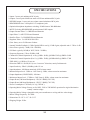
THE NEO-CLASSIC 300B
PREAMPLIFIER RC
OWNER’S MANUAL
TUBES
RULE
rev4.20.11cd
CONTENTS
SECTION
PAGE
INTRODUCTION & GENERAL NOTES
3
MAINS CONNECTIONS
4
CONNECTING YOUR PREAMPLIFIER
5
FIGURE 1 FRONT PANEL
6
FIGURE 2 TOP VIEW
7
FIGURE 3 BACK PANEL
8
OPERATIONAL NOTES
9
REMORA REMOTE CONTROL OPERATING INSTRUCTIONS
10
SPECIFICATIONS14
2
INTRODUCTION
THANK YOU!...
for choosing the Manley Laboratories 300B Preamplifier RC. Handcrafted in Chino, CA, the Neo-Classic 300B Preamplifier RC uses beautiful sounding parts in a clever and clean signal path. This Preamp features the 300B direct
heated triode as the line and headphone driver. The 300B is typically used in low power amplifiers as a power tube.
These 300B-based amps generally deliver 5 to 9 watts single-ended and cost from $3,000 to over $100,000! Some
of these amps sound very nice coupled with efficient speakers. Our Neo-Classic 300B SE/PP Power Amplifier uses
a pair of 300B’s that can be operated single-ended or push-pull, and delivers up to 22 watts. We consider the 300B
to be an extremely luscious tube for low-power purposes. Driving headphones and cables is a natural application for
these tubes. This is where the impedances are not too low and the power requirements are not too high but where
smaller triodes tubes might run out of steam. In our Neo-Classic 300B Preamplifier, we combine the classic 300B
with another classic - the octal-based 6SL7GT dual triode to perform the amplification duties. To complement this
tube choice we also employ tube-based rectification and regulation as well as our usual extreme filtering with gobs of
large filter caps.
To complement our best sounding line driver to date, we surround it with proven passive components such as gold
plated connectors, high purity copper wire, Mil-spec printed circuit boards with extra thick copper and plating, ceramic sockets, and custom-designed transformers. All the audiophile goodies are in here and together the sum total is
a beautiful sounding preamplifier which we know will provide years of faithful service.
LOCATION & VENTILATION
The Neo-Classic 300B Preamplifier must be installed in a stable location with ample ventilation. It is recommended,
if this unit is rack mounted, that you allow enough clearance on the bottom of the preamp such that a constant flow
of air can flow through the ventilation slots. The top should be given enough clearence to allow sufficient ventilation
above the tubes. We also recommend that the preamplifier be placed at least 10 inches away from its amplifier.
WATER & MOISTURE
As with all electronic equipment, this unit should be kept away from moisture of any kind. You’re allowed to weep
with joy at the sounds it makes, but keep those salty tears away from the power supply!
SERVICING
The user should not attempt to service the preamplifier beyond that described in the owner’s manual. Refer all
servicing other than tube replacement to Manley Laboratories.
SPECIAL NOTES
The 300B’s are packaged separately to prevent damage. You will need to carefully plug them in before powering-up
the preamp. Pay attention to the size of the pins to properly align the tubes before inserting. The large pins go into the
large sockets. It is difficult but possible to insert the 300B’s wrong and damage the preamp. Tubes may become loose
during transit. Straighten and press down each tube before plugging the preamplifier into the mains socket. Furthermore, do not touch the tubes while the preamplifier is switched on, as the tubes do become very hot during operation
and should only be handled after the power has been turned off and the tubes have cooled.
Please read over this entertaining and enjoyable owner s manual carefully as it contains information essential
to the proper operation and maximum enjoyment of this instrument.
Thank you again, and please enjoy your new Neo-Classic 300B Preamplifier RC! (and the clever Owner s Manual.)
UNPACKING: Unpack the preamplifier carefully and make sure that all supplied accessories are present. Carefully
examine all items for any possibility of shipping damage. All the tubes should show no signs of distress such as
chipped glass, loose internal components or obvious breakage.
If the preamplifier is damaged or fails to operate, notify the shipper or your dealer or us or your local authorities
immediately. Or if you suspect The Shipping People threw it off the airplane and onto your front porch whilst flying
overhead at 30,000 feet, notify the shipping company without delay and complain to them as we only guarantee this
unit to be able to survive a drop of 23,487 feet or less.
Your Neo-Classic 300B Preamplifier RC was packed with extreme love and includes the following components
and accessories:
a) 1 each, 6 foot IEC 3-conductor power cable (that you will probably replace with an expensive audiophile cord
anyway.)
b) 1 each, Owner s Manual (that we hope you will keep reading.)
c) The tubes: 2 x 300B, 2 x 6SL7GT, 2 x OD3, and 2 x 5U4 vacuum tubes
d) 1 REMORA Remote Control
It is prudent to retain the shipping materials for future use, as they are custom-formed for the preamp and
will greatly minimize the chance of shipping-related damage should you ever need to put your precious
Neo-Classic 300B Preamplifier in the careless hands of The Shipping People again.
3
MAINS CONNECTIONS
Your Neo-Classic 300B Preamplifier RC has been factory set to the correct mains voltage for your country. The
voltage setting is marked on the serial badge, located on the rear panel. Check that this complies with your local supply.
Export units for certain markets have a moulded mains plug fitted to comply with local requirements. If your unit
does not have a plug fitted the coloured wires should be connected to the appropriate plug terminals in accordance with
the following code:
GREEN/YELLOW
BLUE
BROWN
EARTH
NEUTRAL
LIVE
As the colours of the wires in the mains lead may not correspond with the coloured marking identifying the terminals in your plug proceed as follows:
The wire which is coloured GREEN/YELLOW must be connected to the terminal in the plug which is marked
by the letter E or by the safety earth symbol or coloured GREEN or GREEN and YELLOW.
The wire which is coloured BLUE must be connected to the terminal in the plug which is marked by the letter
N or coloured BLACK.
The wire which is coloured BROWN must be connected to the terminal in the plug which is marked by the
letter L or coloured RED.
DO NOT CONNECT/SWITCH ON THE MAINS SUPPLY UNTIL ALL OTHER CONNECTIONS HAVE
BEEN MADE.
Note: This unit has been factory wired for your country. If you plan to take the unit to countries with a different mains voltage you will need to send the unit to a qualified service technician, or contact the Manley Labs
Service Center (email: [email protected]) for the correct transformer primaries wiring conversion.
Alternatively, you may use outboard AC voltage step-up or step-down transformers as appropriate.
100V & 120V Operation: Uses a 0.5A SLO-BLO fuse.
220 & 240V Operation: Uses a 0.25A SLO-BLO fuse.
Waste Electrical and Electronic Equipment (WEEE)
Information for customers:
The European Parliament and the Council of the European Union have issued the Waste Electrical and Electronic Equipment Directive. The purpose of the Directive is the prevention of waste of electrical and electronic equipment, and to promote the reuse and recycling and other forms of recovery of such waste. As such the
Directive concerns producers, distributors and consumers.
The WEEE directive requires that both manufacturers and end-consumers dispose of electrical and electronic equipment and parts in an environmentally safe manner, and that equipment and waste are reused or recovered for their materials or energy. Electrical and electronic equipment and parts must not be disposed of with
normal household wastage; all electrical and electronic equipment and parts must be collected and disposed of separately.
Products and equipment which must be collected for reuse, recycling and other forms of recovery are marked with the following pictogram:
Small products may not always be marked with this pictogram in which case this is present in the instructions for use, on the guarantee certificate and printed on the
packaging.
When disposing of electrical and electronic equipment by use of the collection systems available in your country, you protect the environment, human health and
contribute to the prudent and rational use of natural resources. Collecting electrical and electronic equipment and waste prevents the potential contamination of
nature with the hazardous substances which may be present in electrical and electronic products and equipment.
Your MANLEY or LANGEVIN retailer will assist with and advise you of the correct way of disposal in your country.
4
CONNECTING YOUR PREAMPLIFIER
Setting up your preamplifier is rather easy.
1. Please refer to page 8 for an illustration of the back of the preamplifier.
2. Connect the RCA outputs to the input of your power amplifiers when they are off.
3. UNBALANCED inputs are found on RCA jack inputs and can be connected to any
line level sources such as CD players, tuners or tape decks.
4. All RCA jacks are clearly labeled as to a typical function. Each input is, for all intents
and purposes, functionally and electronically the same. Only the labels are different.
5. The record output is not buffered and it is recommended that one have the tape
feed plugged into the REC OUT only when actually recording. Care should be
used when using a 3-head tape/monitor switch as this record out is not a tape loop.
6. On the left end of the back panel is a standard IEC mains connector. This should
be connected to a standard mains outlet with the supplied cable. This unit has been
hard-wired for the mains voltage in your country
7. Power up the preamplifier FIRST and allow it to settle for a minimum of 30 seconds
before powering up your amplifiers. Turn off your preamplifier and source components LAST when powering down a system. This prevents amplification of turn-on
transients and other noises when powering up or turning a system off and ultimately
protects the speakers.
5
FRONT PANEL
HEADPHONES
VOLUME
OFF
AUX
TAPE
CD
TUNER
VIDEO
A
B
C
D
E
ON
F
A) INPUT SELECT - 5 Position switch for input selection. Each input is electrically identical.
The RECORD OUT directly follows this switch. There is no buffer amp to isolate the effects
of loading and cable capacitance so we recommend disconnecting any interconnect cables from
the RECORD OUT if you are not recording.
B & C) - HEADPHONE JACKS - Standard 1/4” stereo headphone jacks. The
HEADPHONE IMPEDANCE SWITCH (on top of the unit) should be set for the range that
best matches your headphones. The maximum power output primarily depends on the actual
headphone impedance. Typically the preamp can deliver 1 watt (10 volts RMS ) into 100 ohms
and 1 watt (25 volts RMS) into 600 ohms. These outputs are transformer coupled for highest
possible isolation from shock hazards, cable shorts, and other potential problems.
*Note: To use these headphone outputs, you must have the OUTPUT switch (on top of the
unit) set to “TRANSFORMER”. They will not work if that switch is set to “DIRECT”.
D) VOLUME - Audiophile-grade motorized ALPS pot, controllable with the included REMORA Remote Control.
E) BACKLIT PANEL - This is the power indicator. When it is lit-up, your unit is on. When it
is not lit-up, your unit is off.
F) POWER SWITCH - Self explanatory. Because tubes require some time to warm up there
is about 10 seconds of silence followed by “not-so-good sound” before “wow”. The best way to
power up the system is sources ( CD, turntable, etc) first, then this preamp, then after a 30 second wait - turn on the amplifiers. Wait a minute or so - then play tunes. This allows everything
to warm up. Some people hear a difference after an hour or two but it depends on the equipment. Powering down is the opposite order - power amps first. This procedure is a good habit to
follow because it stresses the speakers and ears the least.
The power supply in this preamp is tube based which has the inherant advantage of slow start
(as the tubes warm up). This gives the least stress to the internal components.
6
TOP VIEW
OD3
5U4G
OD3
5U4G
A
300B
300B
B
C
6SL7GT
6SL7GT
A) HEADPHONE IMPEDANCE SWITCH - You should set this switch to best match
your headphones. You may have to look at the specification sheet to get the value in
ohms. If using two sets of phones divide that number in 2. If you don’t have this info then
pick the setting that sounds best - no harm will be done. If the phones are lower than the
switch setting, slight loss of extreme highs may occur. Expect the 300 ohm - 4000 ohm
setting to be louder. Electronically, we are simply either using the two transformer output
windings in series or parallel.
B) TRANSFORMER SWITCH - Switchable between “Direct” and “Transformer”.
Make sure to switch to “Transformer” when using headphones.
C) OUTPUT SWITCH - Switchable between “Line Output” (out to your amplifier) and
“Headphone” (which mutes the Line Out, as you are presumably listening with headphones and don’t need your speakers).
TUBE LOCATIONS - See the diagram above for the proper tube locations. The 300B’s
are not installed during shipping to prevent damage to these tubes. Power should be
unplugged and the tubes cool before handling them. We label the tubes and sockets to
help and so that the calibration we do will be valid in your home. It is possible to put the
300B’s in wrong. Note the two large pins and the two small pins on the base of the tube.
The two large pins go into the two large holes in each tube socket.
CALIBRATION: Each channel is factory-set for 12 dB of voltage gain (1V in = 3.2V
out ) via a pair of trimpots located on the main printed circuit board near the headphone
jacks. These pots adjust the amount of negative feedback in order to exactly match the
gain between both channels. Only 8.5dB of Global Negative Feedback is used which can
be considered minimal. Unless you hear a channel-to-channel imbalance after say, changing tubes, you probably do not have to re-trim the levels. There is no other adjustment that
needs to be made. There is no bias to have to set.
7
REAR PANEL
A
F
C
D
E
B
G
J
H
I
A) MAINS FUSE - Depending on your local power outlet’s voltage, replace with 3A SLOBLO fuse (120 V) or 1.5A SLO-BLO fuse (230V).
B) IEC MAINS SOCKET - Standard IEC mains socket (120/240 VAC as indicated)
C) MAIN OUTPUT - Main left and right outputs driven by 300B’s. Connect these to your
power amplifier inputs when the amps are off.
D) SUBWOOFER OUTPUT - Same as Main Output.
E) RECORD OUTPUT - Set at input line stage level. These normally are connected to a
tape recorder’s inputs. The signal is “picked off” the input selector and before the volume
control. It is a good idea to disconnect any wires connected to these jacks when not recording
to prevent extra loading andcable capacitance from affecting the best possible performance.
F) TUNER INPUT - Connect your tuner outputs here.
G) AUX INPUT - This is where you plug your Aux in - no, not your cattle. “Aux” stands for
Auxilliary and basically means “extra”, so this is just an extra input for any other source that
we didn’t label or you have two of. Any of the input jacks can be used with any Hi-Fi RCA
outputs, as they are electrically identical and only differ in how we labeled them.
H) VIDEO INPUT - Audio actually, from a DVD, Laserdisk, TV, VHS, or BetaMax (or, um,
whatever’s current...) player’s audio output.
I) CD INPUT - Plug in your audio outputs from your CD player or D/A Converter here.
J) TAPE INPUT - Tape machine outputs can be connected here. Be very careful - If the
tape machine inputs are connected to the preamplifier’s RECORD OUTs and the preamp is
switched to TAPE and the tape machine is set to monitor “INPUT” or you start to record beware the dreaded squeal and howl of feedback! One quick “cure” is to not select “TAPE”
on the rotary input selector if these other conditions are met.
8
OPERATIONAL NOTES
SWITCHING ON
The power knob is located on the right hand side of the front panel. Turn the knob to the right
to turn on the preamp, or to the left to turn it off. Don’t ever rock it back and forth rapidly. Note:
on this knob and on the input selector there is a long garolite 1/4” rod shaft that connects the
faceplate knob to the actual switch in the back of the unit. If the knob starts spinning round and
round then the little screws on the shaft-to-switch coupler have come loose. If this happens to
you, UNPLUG the power from the unit, remove the bottom cover, and tighten the 4 x coupler
screws with a 1/6” hex key. No biggie.
RUNNING
It is not recommended that you leave your preamplifier permanently switched on. This only
wastes electricity and tube life. Your preamplifier has both tube and solid state rectification and
reaches peak operating condition in approximately 30 minutes. Also, running is good for your
muscular and cardiovascular health.
TUBE LIFE
As with all tubes, their quality degrades with age. This is due to cathode emission, a natural
process found in all tubes. We recommend that you have your preamplifier checked every 4-5
years, depending on usage. An excessive increase in noise level can indicate the need to replace
the 6SL7 input tubes. 300B’s usually last a very very long time..
HEADPHONES
Select the proper impedence for your headphones with the switch located on the top of the preamp.
Remember, when listening with headphones you MUST have the “Transformer” output selected, not the “Direct” out. Headphones like the transformers a lot.
REPLACING A TUBE? Gently wiggle the tube while pulling it out of the socket. Before putting a new tube in, look at it. Check to see that the pins are straight. Locate the “key” on the
tube’s center locating pin and line that up to the key in the socket. You should be able to gently
push the tube into the socket without excessive force. You can wiggle it in a little bit as you push
down.
HUM? This unit is meant to use the third pin of the mains as the ground reference. Many power amps also use the third pin mains ground. Here we have a potential source of hum caused by
ground loops. Usually a hifi system will want to see the mains ground at only one place. Which
piece of gear should be grounded will have to be determined by experimentation using 3 pin
to 2 pin “cheater” adapters on your power cords. Sometimes one power amp will be grounded
and all other gear will have adapters. Sometimes the better option is to ground the preamp and
“float” the amps. You will have to find out what works best in your system.
Another source of hum can come from equipment stacked on top of one another. Stacking gear
too closely can restrict airflow causing premature componentry failure and it is likely to introduce hum, buzz or noise into the system. Some equipment can radiate strong magnetic fields
outside of its chassis and other gear may be prone to receiving the hum or buzz these fields can
cause. You can move units away from each other to hear if increased distance will solve a hum or
buzz issue.
9
REMORA REMOTE CONTROL
OPERATING INSTRUCTIONS
Quick Start:
Your Remora Remote Control system has been configured and tested at the factory to verify that the communication link between the radio frequency transmitter and the mating receiver-decoder inside the Neo-Classic
300B Preamplifier has been properly established.
Before beginning, ensure that a fresh 9V alkaline battery has been installed in the Remora Remote transmitter.
Yes, we installed a new 9V battery in the Remora Remote when it left the factory.
Turn on the Neo-Classic 300B Preamplifier and after a few seconds, push and hold either the up or down command buttons. The command is sent via radio signal to the preamplifier and the motorized volume control will
react by moving as directed by the remote switch activation, with motor action occurring as long as a button is
engaged. The Remora Remote transmitter’s multi-colored LED lamp will glow bright GREEN when a command is being sent.
Notice that the volume control motion will stop when the control reaches the travel end-stops, just as it does
when the knob is turned by hand. Also notice that the remote will stop transmitting if either the up or down
buttons are pressed for more than 30 seconds.
The multi-colored LED lamp on the face of the remote will tell you when the 9V battery needs to be replaced.
The battery is GOOD when the lamp is bright GREEN while the transmitter is active. As the battery voltage
wanes, the green light may flash RED briefly when the transmitter is switched on; that’s when the load on the
battery is heaviest. When the battery is nearing exhaustion, the time interval of the RED flash will expand, and
eventually and the battery nears life end, the lamp may stay RED more or less continuously. When the LED
lamp stays RED, then the moment has arrived for mandatory replacement of the battery.
You may replace the battery at your leisure, since all the Remora Remote transmitter’s settings are held safely
and indefinitely, in the microprocessor’s non-volatile flash memory.
More Details:
Here are some details about the features included with your new Remora Remote system. Some are pretty
obvious; others are riding just below the surface.
First, the Remora radio-frequency remote control system consists of four parts.
1. The microprocessor-controlled battery-operated hand-held RF transmitter
2. The line-operated RF receiver
3. The microprocessor-controlled decoder and motor drive amplifier
4. The dual-deck motorized volume control
Using computer-based hardware on both sides of the system adds flexibility and allows enhanced features to
be added with little impact on system cost. For example, one such feature is the ability of the receiver-decoder
to discriminate between interfering signals, or other Manley Remora Remote enabled preamplifier models so
that it will react only to the prescribed remote transmitter.
...Please read on for more Remora Writings...
10
Remora Remote Features!
1. Remote transmitter and receiver operate under crystal-clocked microprocessor control for maximum signal
discrimination, flexibility, and system range.
2. The user may easily reprogram the user-number portion of the remote system’s serial I.D. data stream. This
will eliminate the possibility of undesired operation due to remote command collisions.
3. Multi-color LED displays battery condition when the transmitter is in use, as well as two-digit user-number
programming status when in program mode.
4. Internal antennas contribute to sleek design aesthetics and eliminate possibility of damage to them had they
been subject to external exposure, while still providing good range.
5. Transmitter uses readily-available 9V battery.
6. Transmitter shell made of tough Lexan® for durability.
7. Real compression-dome push buttons instead of short-lived conductive silicone membrane pads are used for
years of dependable operation.
8. Highest quality motorized attenuator employed for critical audio path with very good inter-channel matching (no silicon attenuators here!)
9. Two-step attenuator rotation speed: Press and hold a button; for the first half second the attenuator motor runs slowly so the user may “nibble” at the volume setting. After half of a second, the motor rotation rate
doubles to move things right along.
10. Remote transmitter keep-alive interval keeps Remora Remote awake for a few seconds AFTER either button is released, as indicated by the LED lamp glowing DIM green or red. Keeping the microprocessor awake
shaves a few dozen milliseconds off of the wake-up time, and helps to make the remote system more responsive.
11. Flash memory inside both the transmitter’s and the receiver-decoder’s CPU eliminates the need for backup batteries or super-caps, etc.
12. Clever system architecture and user-programming procedure eliminates the need for dip-switches and associated fiddling with awkward dip switch arrays.
13. Remora Remote consumes very little power which yields long battery life.
14. Electrically quiet operation preserves low noise floor of the preamplifier’s audio path.
15. Discrete passive volume control offers highest headroom option over silicon-based devices.
Precautions when using the Remora Remote system:
Use only fresh alkaline 9-volt (006P) batteries in the remote transmitter. The power draw is small during
transmit events, and nil when on standby. Unless the transmitter is used very heavily, the battery should last
for at least a year, or for about 10 hours of continuous transmit time. If the remote not used very often then the
battery life should equal its shelf life.
The remote transmitter operates on 433.9 MHz, and features a tuned antenna for reasonable efficiency and
extended battery life. As with other RF equipment of this sort, the range can be influenced if the antennas on
either side of the link are hampered by obstructions that deflect or attenuate the radio signal. Neither the transmitter nor the receiver should be used or placed behind conductive surface planes, or on top of large metal
cabinetry, since this can effectively reduce or block the radio signals.
The tuned antenna is positioned at the top or “nose” of the transmitter housing. Best range can be obtained by
keeping your hand clear of the top of the enclosure during operation. Range may be severely cut if the remote
is placed on a conductive (metal) surface, such as a filing cabinet or other piece of equipment, since the metal
plane will grossly detune the antenna. When the transmitter is operated in the palm of your hand, you may
expect the remote range to be at least 15 meters line-of-sight, typically 20 meters (or more) in most settings.
Radio-based systems can be affected by noise or interference occurring on the operating channel. Various government bureaucracies dictate what radio channels may be used depending on several factors such as country
where the remote system is to be operated, the exact nature of the transmitted information and so forth. Because of these limitations, the channels used for remote controls of this sort can be crowded, especially where
population density is high. In addition to on-channel interference, the desired radio signal may be received
perfectly when the remote transmitter is in one location, but mysteriously “drop out” when the transmitter is
move a few inches one way or another. The transmitter may need to be rotated or relocated slightly to avoid
RF “null” points.
11
The Remora system is highly resistant to false operation due to noise or other remote signals, but the range
will be reduced if the competing signals or noise is very strong. If you experience intermittently poor range,
briefly try operating the equipment at another location free of possible sources of interference before contacting your dealer or Manley Labs.
Keep the remote and all other parts of the system away from rain or moisture of any sort. The Remora Remote’s circuitry is extremely intolerant of moisture intrusion. In the event the remote transmitter gets wet,
remove the battery immediately, disassemble the case and try to remove as much moisture as possible as soon
as you can. Then let the assembly air-dry in a warm place for a day before re-assembling and testing. DO NOT
disturb any trimpot settings or move the antenna components.
Remove the battery promptly when it becomes weak or discharged or if the remote transmitter is not going to
be used for a protracted period of time. This will help prevent corrosion due to battery leakage.
The motorized volume attenuator may safely be actuated by hand, or by the motor under remote command.
The attenuator has a slip-clutch transmission, so it is safe to occasionally over-ride the motorized action by
hand, or let the clutch slip after the attenuator reaches its end stop. However, the motorized attenuator assembly will last longer if these actions are avoided.
How to establish the digital link (pairing) between the Remora transmitter and the receiver:
Each transmitter and receiver-decoder set is designed to respond to a specific data string as programmed into
the transmitter and later acknowledged by the receiver-decoder. A small set of user-defined user-numbers is
used as part of the data string so that the remote system can be programmed to avoid unwanted operation of
another Remora-enabled Manley preamplifier that may be nearby, in range of the transmitter.
If necessary, you may alter the specific short user-number of the transmitter. When you do so, the receiver can
easily be reprogrammed to follow the changes and react to the new user-number. Having unique handshake
ID codes is important for RF remotes since unlike infrared systems, the remote’s RF commands can penetrate
walls, floors, and doors, which might operate other Manley Remora-enabled gear if they all had the same usernumbers!
The user-numbers are a pair of single-digit numbers created by hitting the up and down buttons during a
remote transmitter programming session. How to program the user-numbers is one of those procedures that is
harder to write down than to actually do physically.
To get acquainted with the remote transmitter itself, we’ll start with a simple matter of determining the Remora Remote’s user-number setting without changing the user-number. This requires only one action by you, the
user. You’ll get to see some of the Remora Remote’s “modes” as indicated by the LED lamp.
How to query the Remora transmitter to see what user-number is already programmed:
Press and hold both the up and down buttons for about 0.5 seconds. Release the buttons when you see the LED
change from dim green to flashing dim yellow.
The LED will flash dim yellow for about three seconds. Be careful not to touch any buttons while the LED is
flashing dim yellow as the remote is in the program mode during this time.
The flashing dim yellow LED will time out and will then go dark for a moment. Then the LED will recite the
user-number by flashing a string of GREEN (up) blinks, then a string of RED (down) blinks. The user-number
may range from the smallest value of 1 green, 1 red (1,1) up to a maximum of 7 green and 7 red (7,7). As you
can see, up to 49 different user-numbers are available.
Once the user-number readout event lapses, the remote falls back to normal operation.
How many GREEN blinks?
(----- , -----) How many RED blinks?
UP
This is your user-number.
DOWN
12
How to change the user-numbers and re-pair the system:
Ordinarily there will seldom be a need to change the user-number. Changing the user-number requires a few
more ballet steps, as listed below. Some steps are time-window sensitive to help prevent pairing errors due to
interference from other signals on the radio channel.Please read over the list of required actions and LED reactions completely before attempting to reprogram your Remora system user-number.
1. Make sure the Neo-Classic 300B preamplifier is plugged into the mains power line, but turned off, and
make sure that the battery in the Remora Remote transmitter is healthy.
2. Put the Remora Remote into the programming mode by pressing the up and down buttons simultaneously
for about a half second. The LED will blink yellow to indicate that it is in programming mode.
3. While the LED is blinking yellow, enter the new user-number by tapping the “UP” button 1 to 7 times,
followed by pressing the “DOWN” button 1 to 7 times. Example: 3 “ups” and 2 “downs” will set a new usernumber to (3,2). After it has accepted your new code, yellow blinking LED will stop blinking and will then
read back the new user-number you set by displaying 3 GREEN blinks followed by 2 RED blinks. BE CAREFUL NOT to touch the buttons once the read-back has happened; the remote knows you have reprogrammed
it, and it is “armed” with a special data string to tell the receiver-decoder that a user-number change has happened.
4. With the Remora Remote in this “armed” state and with it in your hand with your thumb hovering over either button, power on your Neo-Classic 300B Preamplifier by turning the power switch to the “ON” position.
Once the preamplifier’s badge lamp is lit, you have about 1.5 seconds to press either button on the remote. The
preamplifier should now respond by rotating the volume control in the direction of which ever button has been
pressed. Pairing is now complete.
For the first 1.5 seconds after power-up, the Neo-Classic 300B Preamplifier’s receiver-decoder is configured to
be in programming mode looking for any new user-number changes. If the decoder detects the new user-number programming string from an “armed” remote during this 1.5 second interval, the decoder will immediately
discard the old user-number and adopt the new one before resuming normal operation.
In the event that you lose or damage your Remora Remote, a new one can be supplied pre-programmed with
your user-number if you provide it to us. Otherwise, it is a straightforward matter to observe, note, and re-pair
the Remora Remote’s user-number to the preamplifier using the query and programming procedure described
earlier.
Please direct any comments or questions to your dealer or to Manley Labs for further assistance.
** FCC STATEMENT **
This equipment has been tested and found to comply with the limits for a class B digital device, pursuant to
part 15 of the FCC Rules. These limits are designed to provide reasonable protection against harmful interference in a residential installation. This equipment generates, uses and can radiate radio frequency energy and
if not installed and used in accordance with the instructions, may cause harmful interference to radio communications. However, there is no guarantee that interference will not occur in a particular installation. If
this equipment does cause harmful interference to radio or television reception, which can be determined by
turning the equipment off and on, the user is encouraged to try to correct the interference by one or more of the
following measures:
* Reorient or relocate the receiving antenna.
* Increase the separation between the equipment and receiver.
* Connect the equipment into an outlet on a circuit different from that to which the receiver is connected.
* Consult the dealer or an experienced radio/TV technician for help.
Operation with non-approved equipment is likely to result in interference to radio and TV reception. The user
is cautioned that changes and modifications made to the equipment without the approval of manufacturer
could void the user’s authority to operate this equipment.
13
SPECIFICATIONS
* Inputs: 5 stereo pair unbalanced RCA jacks
* Outputs: 2 stereo pairs MAIN out same as SUB out unbalanced RCA jacks
* RECORD output: 1 stereo pair pre-volume control unbalanced RCA jacks
* HEADPHONE Outs: 2 front panel 1/4” headphone jacks
* Optimized headphone impedance switching: 30-400 ohms to 300-4000 ohms
* MUTE: Selecting HEADPHONE operation mutes LlNE outputs
* Output Vacuum Tubes: 2 x 300B Electro-Harmonix
* Input Tubes: 2 x 6SL7GT Electro-Harmonix
* Rectifier Tubes: 2 x 5U4GBEH Electro-Harmonix
* Regulator Tubes: 2 x OD3 NOS JAN USA
* Gain: factory set at 12 dB at max Volume
* Internal Variable Feedback: 8.5 dB of global NFB is used @ 12 dB of gain, adjustable trim -1.7dB to +1dB
* Noise Floor: typically -70 dB (1 Hz - 100 KHz)
* S/N Ratio: typically 105 dB (A WGT, 20 Hz - 20 KHz)
* Frequency Response: 5 Hz to 50 KHz ±1dB
* Channel-to-Channel Separation (L to R): @1KHz 48 dB; @10KHz 35 dB; @20KHz 34 dB
* Channel-to-Channel Separation (R to L): @1KHz 50 dB; @10KHz 40 dB; @20KHz 37 dB
* THD: 0.08 % @ 1KHz at 1V rms out
* Distortion THD+N: -80 dB (.01 %) zero “crossover” distortion, mostly 2nd harmonic
* Input Sensitivity: 250mV (-9.8dBu) yields 1V out
* Input Impedance: 100 Kohm motorized ALPS volume control
* Maximum Input Level: 5.5dBu or 1.459 Vrms @ 1KHz, volume control at maximum
* Output Impedance (LINE STAGE): 100 ohms
* Maximum Output Level: 17.2dBu or 5.636 Vrms @ 1KHz, volume control at maximum
* Output Power (100 ohm Headphones): 1W (10 V RMS) (28 V P-P)
* Output Power (600 ohm Headphones): 1W( 25 V RMS) (70 V P-P)
* Power Consumption: 170 Watts (1.4 A @ 120VAC)
* Operating Mains Voltage: Factory set for 100V, 120V or 220-240VAC operation for original destination country’s mains voltage.
* Operating Mains Voltage: changeable with power transformer re-wiring and fuse value change.
* Mains Voltage Frequency: 50~ 60Hz
* Dimensions: W=19”. L=13”. H=3 1/2”
* Shipping Weight: 28 Ibs.
14