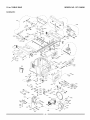
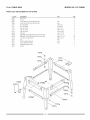
1
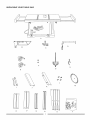
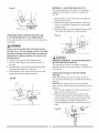
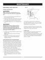
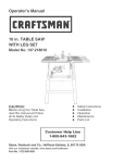
Operator's Manual
®
10 in. TABLE SAW WiTH STAND
Model No, 137.218030
CAUTION:
Before using this Table Saw,
read this manual and follow
all its Safety Rules and
Operating instructions
Customer
Help
For Technical
Visit our Craftsman
Support
website:
o
e
Operation
Maintenance
•
Parts List
Repair
Parts
Center
1-800-488-1222
and Co., Hoffman
Part No. 137218030001
Safety Instructions
Installation
Sears
Line
1-800-843-1682
Sears, Roebuck
e
•
Estates,
www.sears.comlcraftsman
IL 60179 USA
&
SECTION
PAGE
Warranty ........................................
2
Product Specifications .......................
2
Power Tool Safety .............................
3
Table Saw Safety ..................................
4
Electrical Requirements and Safety ...... 5
Accessories and Attachments ..............
6
Tools Needed For Assembly ................
6
Carton Contents ....................................
6
ONE=YEAR
SECTION
Know Your Table Saw ...........................
Glossary of Terms .................................
Assembly and Adjustments .................
Operation .............................................
Maintenance ....................................
Troubleshooting Guide ........................
Parts List .............................................
Push Stick Plan ...................................
FULL WARRANTY
ON CRAFTSMAN
PAGE
8
9
10
17
22
23
24
28
TOOL
if this Craftsman tool fails due to a defect in material or workmanship within one year from the date of purchase,
CALL 1-800-4-MY-HOME® TO ARRANGE FOR FREE REPAIR (or replacement if repair proves impossible).
if this tool is used for commercial or rental purposes, this warranty will apply for only ninety days from the date of
purchase. This warranty applies only while this tool is in the United States.
This warranty gives you specific legal rights, and you may also have other rights, which vary, from state to state.
Sears,
Roebuck
and Co., Hoffman
Estates,
IL 60179
IAkWARNING
I
Some dust created by power sanding, sawing, grinding,
drilling and other construction activities contains
chemicals known to cause cancer, birth defects or other reproductive
chemicals are:
•
•
harm. Some examples of these
Lead from lead-based paints
Crystalline silica from bricks, cement and other masonry
products
• Arsenic and chromium from chemically treated lumber
Your risk from these exposures varies, depending on how often you do this type of work. To reduce your
exposure to these chemicals, work in a well ventilated area and work with approved safety equipment such as
dust masks that are specially designed to filter out microscopic
particles.
MOTOR
SAW
Type ..........................................................
Universal
Amps .........................................................
Voltage ......................................................
Hz ..............................................................
15
120
60
RPM (no load) ...........................................
5000
[A WARNING]
Rip Capacity With Extension ......... 24 in. Right & Left
Blade Size .................................... 10 in.
Blade Arbor Size .......................... 5/8 in.
Maximum
Maximum
Maximum
Maximum
Cut Depth @ 90 ° ..........
Cut Depth @ 45 ° ..........
Diameter Dado .............
Dado Cut Width ............
3 in.
2-1/2 in.
6 in. (Stackable only)
1/2 in.
To avoid electrical hazards, fire hazards or damage to the tool, use proper circuit protection.
This tool is wired at the factory for 110-120 Volt operation, it must be connected to a 110-120 Volt / 15 Ampere
time delay fuse or circuit breaker. To avoid shock or fire, replace power cord immediately if it is worn, cut or
damaged in any way.
Before using your tool, it is critical that you read and understand these safety rules. Failure to follow these
rules could result in serious injury to you or damage to the tool.
GENERAL SAFETY iNSTRUCTiONS
Read and understand all the instructions below before using the power tool. These safety instructions are not
meant to cover every possible condition that could occur. As with any power tool, common sense, vigilance
and due care must be used.
READ and become familiar with this entire
Operator's Manual. LEARN the tool's applications,
limitations and possible hazards.
2.
[A wAn.I.GJ
Look for this symbol that identifies important safety
precautions. It means BE ALERTt YOUR SAFETY IS
iNVOLVED!
3.
NEVER OPERATE THIS MACHINE WITHOUT THE
SAFETY GUARD iN PLACE FOR ALL THROUGH=
SAWING OPERATIONS.
4.
DO NOT USE iN A DANGEROUS ENVIRONMENT
such as damp or wet locations or in the rain. Keep
work area well lighted.
5.
DO NOT use power tools in the presence of
flammable liquids or gases.
6.
KEEP WORK AREA CLEAN. Cluttered areas and
benches invite accidents.
7.
KEEP CHILDREN AWAY. All visitors should be
kept at a safe distance from the work area.
8.
DO NOT FORCE THE TOOL. It will do the job
better and safer if used at the rate for which it was
designed.
9.
USE THE RIGHT TOOL. Do not force the tool or
attachment to do a job for which it is not designed.
10. WEAR PROPER APPAREL. DO NOT wear loose
clothing, gloves, neckties, rings, bracelets or other
jewelry that may get caught in moving parts. Nonslip footwear is recommended. Wear protective hair
covering to contain long hair.
11. WEAR A FACE MASK OR DUST MASK. Sawing,
cutting and sanding operations produce dust.
12. DISCONNECT TOOLS before servicing and when
changing accessories, such as blades, cutters, etc.
13. REDUCE THE RISK OF UNINTENTIONAL
STARTING. Make sure the switch is in the OFF
position before plugging tool into the power supply.
adjusting wrenches are removed from the tool
before turning ON.
16. NEVER LEAVE TOOL RUNNING UNATTENDED.
TURN THE POWER OFF. Do not leave the tool
before the blade comes to a complete stop.
17. NEVER STAND ON TOOL. Serious injury could
occur if the tool is tipped or if the cutting tool is
unintentionally contacted.
18. DO NOT OVERREACH.
balance at all times.
Keep proper footing and
19. MAINTAIN TOOLS WITH CARE. Keep tools sharp
and clean for most efficient and safest performance.
Follow instructions for lubricating and changing
accessories.
20. CHECK FOR DAMAGED OR LOOSE PARTS.
Check for alignment of moving parts, binding
of moving parts, loose mounting and any other
conditions that may affect its safe operation. A
guard or other part that is loose or damaged should
be properly adjusted, repaired or replaced.
21. MAKE WORKSHOP CHILDPROOF with padlocks,
master switches or by removing starter keys.
22. DO NOT operate the tool if you are under the
influence of any drugs, alcohol or medication that
could impair your ability to use the tool safely.
23. USE A DUST COLLECTION SYSTEM whenever
possible. Dust generated from certain materials can
be hazardous to your health and, in some cases,
a fire hazard. Always operate the power tool in a
well-ventilated area with adequate dust removal.
24. ALWAYS WEAR EYE PROTECTION. Any power
tool can throw debris into your eyes that could
cause permanent eye damage. ALWAYS wear
safety goggles (not glasses) that comply with ANSI
safety standard Z87.1. Everyday glasses have only
impact resistant lenses. They ARE NOT safety
glasses.
NOTE: Glasses or goggles not in compliance with
ANSI Z87.1 could cause serious injury when they
break.
14. USE ONLY RECOMMENDED ACCESSORIES.
Consult the Operator's Manual for recommended
accessories. The use of improper accessories may
cause injury to you or damage to the tool.
25. DiRECTiON OF FEED. Feed work into a blade or
cutter against the direction of rotation of the blade or
cutter only.
15. REMOVE ADJUSTING KEYS AND WRENCHES.
Form the habit of checking to see that keys and
26. DO NOT loan your tool to a neighbor or
friend without providing him/her with the
Operator's Manual. Be sure he/she learns the tool's
applications and possible hazards.
ALWAYS USE SAW BLADE GUARD, splitter
and anti-kickback pawls for every through-sawing
operation. Through-sawing operations are those
in which the blade cuts completely through the
workpiece when ripping or crosscutting. Always be
sure blade guard is tightened securely.
2.
3.
4.
you) by keeping the blade sharp, the rip fence
parallel to the saw blade and by keeping the splitter,
anti-kickback pawls and guards in place, aligned
ALWAYS HOLD WORK FIRMLY against the miter
gauge or rip fence.
and functioning. Do not release work before passing
it completely beyond the saw blade. Do not rip work
that is twisted, warped or does not have a straight
ALWAYS USE a push stick, especially when ripping
narrow stock. Refer to ripping instructions in this
Operator's Manual where the push stick is covered
in detail. A pattern for making your own push stick is
included on page 28.
edge to guide it along the fence. Do not attempt to
reverse out of a cut with the blade running.
NEVER PERFORM ANY OPERATION FREEHAND,
which means using only your hands to support or
guide the workpiece. Always use either the fence or
the miter gauge to position and guide the work.
[,_
DANGER
J
FREEHAND CUTTING IS THE MAJOR CAUSE OF
KICKBACK AND FINGER/HAND AMPUTATIONS.
NEVER USE THE MITER GAUGE AND FENCE
SIMULTANEOUSLY.
5.
12. PROVIDE ADEQUATE SUPPORT to the rear
and the sides of the saw table for long or wide
workpieces.
13. AVOID KICKBACKS (work thrown back towards
NEVER STAND or have any part of your body in
line with the path of the saw blade. Keep your hands
out of the saw blade path.
14. AVOID AWKWARD
OPERATIONS
and hand
positions where a sudden slip could cause your
hand to move into the saw blade.
15. NEVER USE SOLVENTS to clean plastic parts.
Solvents could possibly dissolve or otherwise
damage the material. Only a soft damp cloth should
be used to clean plastic parts.
16. MOUNT your table saw on a bench or stand
before performing any cutting operations. Refer to
ASSEMBLY on page 10.
17. NEVER CUT METALS or materials that may make
hazardous dust.
18. ALWAYS USE IN A WELL-VENTILATED
6.
NEVER REACH behind or over the cutting tool for
any reason.
7.
AREA.
Remove sawdust frequently. Clean out sawdust
from the interior of the saw to prevent a potential fire
hazard.
REMOVE the rip fence when crosscutting.
19. NEVER LEAVE THE SAW RUNNING
8.
DO NOT USE a molding head with this saw.
UNATTENDED.
Do not leave the saw until the
blade comes to a complete stop.
9.
FEED WORK INTO THE BLADE against the
direction of rotation only.
20. FOR PROPER OPERATION follow the instructions
in this Operator's Manual entitled OPERATION
10. NEVER use the rip fence as a cut-off gauge when
(Page 17).
crosscutting.
NOTE: On machines with no stand or if stand is not
11. NEVER ATTEMPT TO FREE A STALLED SAW
BLADE without first turning the saw OFF. Turn
power switch OFF immediately to prevent motor
damage.
being used, a hole approximately 11 in. square must
be cut under saw to allow sawdust to fall through.
Failure to cut this hole will allow sawdust to build up
in the motor area, resulting in a fire hazard and
potential motor damage.
GROUNDING
iNSTRUCTiONS
tN THE EVENT OF A MALFUNCTION OR
BREAKDOWN, grounding provides a path of least
resistance for electric currents and reduces the risk of
electric shock. This tool is equipped with an electrical
cord that has an equipment-grounding conductor
and a grounding plug. The plug must be plugged
into a matching receptacle that is properly installed
and grounded in accordance with all local codes and
ordinances.
DO NOT MODIFY THE PLUG PROVIDED. If it will not
fit the receptacle, have the proper receptacle installed
by a qualified electrician.
IMPROPER CONNECTION of the equipment grounding
conductor can result in risk of electric shock. The
conductor with the green insulation (with or without
yellow stripes) is the equipment grounding conductor.
tf repair or replacement of the electrical cord or plug is
necessary, do not connect the equipment grounding
conductor to a live terminal.
CHECK with a qualified electrician or service person
if you do not completely understand the grounding
instructions, or if you are not certain the tool is properly
grounded.
or a #14 wire with a 15 A time-lag fuse. NOTE: When
using an extension cord on a circuit with a #14 wire, the
extension cord must not exceed 25 feet in length. Before
connecting the motor to the power line, make sure the
switch is in the off position and the electric current is
rated the same as the current stamped on the motor
nameplate. Running at a lower voltage will damage the
motor. This tool is intended for use on a circuit that has
a receptacle like the one illustrated in Fig. 1.
Fig. 1 shows a three-pronged electrical plug and
receptacle that has a grounding conductor. If a properly
grounded receptacle is not available, an adapter (Fig. 2)
can be used to temporarily connect this plug to a twocontact grounded receptacle. The adapter (Fig. 2) has a
rigid lug extending from it that MUST be connected to a
permanent earth ground, such as a properly grounded
receptacle box.
CAUTION
In all cases, make certain the receptacle is properly
grounded, if you are not sure, have a qualified
electrician check the receptacle.
CAUTION
This tool is for indoor use only. Do not expose to
rain or use in damp locations.
Fig. 1
ged Plug
USE only three-wire extension cords that have threepronged grounding plugs with three-pole receptacles
that accept the tool's plug. Repair or replace damaged
or worn cords immediately.
GUiDELiNES
FOR EXTENSION
g Prong
Properly Grounded
Three-Pronged Receptacle
CORDS
USE THE PROPER EXTENSION CORD. Make sure
your extension cord is in good condition. Use an
extension cord heavy enough to carry the current your
product will draw. An undersized cord will cause a drop
in line voltage resulting in loss of power,
overheating and burning out of the motor. The table on
the right shows the correct size to use depending on
cord length and nameplate ampere rating, tf in doubt,
use the next heavier gauge. The smaller the gauge
number, the heavier the cord.
Make sure your extension cord is properly wired and in
good condition. Always replace a damaged extension
cord or have it repaired by a qualified technician before
using it. Protect your extension cords from sharp
objects, excessive heat and damp or wet areas.
Use a separate electrical circuit for your tool. This circuit
must not be less than #12 wire with a 20 A time-lag fuse
Grounding Lug
Fig. 2
Make sure this is
connected to a
known ground.
Two-Pronged
Receptacle
Adapter
CAUTION
This tool must be grounded while in use to protect
the operator from electric shock.
'
O"
•
O'm
'
(When using 120 volts only)
Ampere Rating
Total length of Cord
MoreThan
Not MoreThan 25ft. 50ft. 100ft. 150ft.
0
6
8
16
16
14
6
10
10
12
8
6
I6
16
14
14
12
12
RECOMMENDED
[_
WARNING
ACCESSORIES
UNPACKING
I
Visit your Sears Hardware Department
or see the
Craftsman Power and Hand Tools Catalog to purchase
recommended accessories for this power tool.
AND CHECKING
CONTENTS
Separate all parts from packing materials. Check each
part with the illustration on the next page and the "Table
of Loose Parts" to make certain all items are accounted
for, before discarding any packing material.
[A WARNING
I
IA WARNING
I
To avoid the risk of personal injury:
• Do not use adjustable (wobble) type dadoes or
if any part is missing or damaged, do not attempt
to assemble the table saw, plug in the power cord,
•
•
carbide tipped dado blades.
Only use stackable dadoes.
Maximum dado width is 1/2".
•
Do not use a dado with a diameter
•
•
Do not use molding head set with this saw.
Do not modify this power tool or use accessories
not recommended
by Sears.
larger than 6".
or turn the switch ON until the missing or damaged
part is obtained and is installed correctly. To avoid
electric shock, use only identical replacement
parts when servicing double insulated tools. Call
1=800=4-MY=HOME® for replacement
TABLE
ITEM
A
B
C
SUPPLIED
Blade wrench
NOT SUPPLIED
Medium screwdriver
#2 Phillips screwdriver
Blade wrench
[ II
II
II
III
II
OF LOOSE
parts.
PARTS
D
E
F
DESCRIPTION
Table saw assembly
Blade guard and splitter ass'y
Bolt, flat washer, toothed washer,
oval washer, spring washer
Rip fence, handle & nut
Handwheel
Dome nut
QUANTITY
1
1
1 each
G
H
t
J
Miter gauge
Hex key
Blade wrench
Left table extension fence
1
2
2
1
K
L
M
Right table extension fence
Locking knob
Blade
1
4
1
Short upper support
Long upper support
Short bottom support
Long bottom support
Leg
Stand mounting hardware bag
2
2
1
2
2
I
Straight edge
3 mm Hex Key
STAND
O
P
4 mm Hex Key
Adjustable wrench
I 'i't'l'I"l'i'l
'i"l:_
Combination square
Q
R
S
T
2
2
4
1
NOTE: To make assembly easier, keep contents of box
together. Apply a coat of automobile wax to the table.
Wipe all parts thoroughly with a clean dry cloth. This will
reduce friction when pushing the workpeice. To avoid
injury, the styrofoam block should be removed between
the motor and the table.
UNPACKING
YOUR TABLE
SAW
1
A
H
G
E
L
t
J
o
I o
K
M
[1
G
i
[1
i
O
[1
[1
P
t
Blade guard
Miter gauge
Side table extension
Rip fence
_
Table insert
Table
Left extension fence
Right extension fence
Extension fence lock knob
Blade bevel lock knob
Blade tilt pointer
Blade tilting handwheel
Blade tilt scale
Blade elevation
handwheel
ON/OFF switch
with safety key
Overload reset switch
- Rip fence storage hook
Miter gauge storage
Stand
Front stand mounting holes
Anti-kickback
pawls
Blade
Splitter
Splitter bracket
Blade wrenches
Rear mounting holes
ANTFKICKBACK
PAWLS- Prevents
theworkpiece
frombeingkickedupwardor backtowardthefrontof the
tablesawbythespinningblade.
OVERLOAD
RESETSWITCH
- Resetsthe
thermocouple
andprovidesa wayto restartthesaw
motorif it overloads
oroverheats.
ARBOR- Theshaftonwhichthebladeordadois
mounted.
PUSHSTICK- Specialaccessory
thatis usedtopush
workpieces
whenperforming
rippingoperations.
BEVELCUT- Ananglecutmadethroughthefaceof
theworkpiece.
RESIN- A stickysapthathashardened.
BLADEBEVELSCALE- Measures
theangletheblade
is tiltedwhensetfora bevelcut.
BLADEELEVATION
HANDWHEEL
- Raisesand
lowerstheblade.
BLADEGUARD- Clearplasticcoverthatpositions
itselfoverthebladewhilecutting.
COMPOUND
CUT- Asimultaneous
bevelandmiter
cut.
CROSSCUT - A cut made across the width of the
workpiece.
DADO - Special cutting blades that are used to cut
grooves in a workpiece.
FREEHAND - Performing a cut without using a rip
fence, miter gauge, hold down or other proper device to
prevent the workpiece from twisting during the cutting
operation.
GUM - A sticky sap from wood products.
HEEL - Misalignment of the blade.
REVOLUTIONS
PERMINUTE(RPM)- Thenumberof
turnscompleted
bya spinningobjectinoneminute.
RIPFENCE- A guideusedforripcuttingwhichallows
theworkpiece
tocutstraight.
RiPPiNG-
Cutting with the grain of the wood or along
the length of the workpiece.
SAW BLADE PATH - The area of the workpiece or
table top directly in line with the travel of the blade or the
part of the workpiece that will be cut.
SET - The distance between two saw blade tips, bent
outward in opposite directions to each other. The further
apart the tips are, the greater the set.
SPLITTER - Keeps the workpiece split apart after being
cut to prevent binding on the blade and workpiece.
TABLE INSERT - Metal insert that is removed from the
table to install / remove blades, tt is also removed for
dado cutting. When dado cutting, a dado insert plate
must be used.
THROUGH- SAWING - Making a cut completely
through the length or width of a workpiece.
WORKPIECE - Material to be cut.
JAM NUT - Nut used to lock another nut in place on a
threaded rod or bolt.
Leading edge
KERF - The amount of material removed by the blade
cut.
Saw blade path
Kerf
Surface
MITER CUT - An angle cut made across the width of
the workpiece.
Trailing edge
MITER GAUGE - A guide used for crosscutting
operations that slides in the table top channels (grooves)
located on either side of the blade, it helps make
accurate straight or angle crosscuts.
Workpiece
ASSEMBLESTAND(FIG.A)
1. Unpackallpartsandgroupbytypeandsize(Fig.A).
Referto partslistforquantities.
2. Attachonelonguppersupport(P)totopofleg(S)
usingonesquareneckbolt(1)andnut(2).
NOTE:
• Aligndetentsinstandlegwithsupportbracketsto
ensureproperfit.
• Donottightenboltsuntilstandis properly
aligned(seestep#8 beforetightening).
3. Attachotherendof longuppersupporttotopof
anotherlegusingonesquareneckboltandnut.
4. Attachonelongbottomsupport(R)tocenterofeach
legusingsquareneckboltsandnuts.Thiscompletes
thefrontframesection.
5. Assemblerearframesectioninexactlythesame
way.
6. Joinfrontandrearframeassemblies
usingtwo
shortuppersupports(O)andtwoshortbottom
supports(Q),squareneckboltsandnuts.
7. Insertlargehexheadbolt(3)intorubberfoot(4)and
insertintobottomof leg.Fastenwithwasher(5)and
nut(6).Repeatforeachleg.
8. Attachthehook(7)totheleftofthestandwithbolt(8)
andnut(9)forthe mitergaugestorage.Attachthe
hook(12)totherightofthestandwithboltandnut
forthe ripfencestorage.
9. Placestandonlevelsurfaceandadjustso alllegs
arecontacting
thefloorandareatsimilarangles
tothefloor,anddetents(13)in standlegalignwith
supportbrackets,thentightenallbolts.
NOTE:Standshouldnotrockafterall boltsare
tightened.
ASSEMBLE
TABLESAWTOSTAND(FIG.A, B)
1. Placeprotective
corrugated
cardboard
oroldblanket
onfloortoprotectthesawtablesurface.
2. Placethesawup-sidedownontheprotective
material(Fig.B).
3. Positionthestandup-sidedownonthesawbase.
NOTE:Makesurefrontofstandandfrontof saware
facingthesamedirection.
4. Lineupthefourholesinsawbaseandstand.
5. Fastensawtostandusingfourbolts(10),washers
(11) andnuts(8).
NOTE:Placewasheroneach bolt before inserting
into saw base and through the support. Nut must be
flush against the bracket (see Fig. A).
6. Tighten all four nuts.
7. Carefully set the saw in its upright position on a clean
level surface.
NOTE: DO NOT OVER TIGHTEN NUTS HOLDING
SAW TO STAND. THIS MAY DAMAGE THE SAW
BASE.
IA WARNING
I
IF THE STAND WILL NOT BE USED, DO NOT
OPERATE THE TABLE SAW ON THE FLOOR. THIS
IS A VERY DANGEROUS POSITION.
Fig, B
Fig, A
Q
S
10
STORAGE (FIG. B=f, FiG. B-2)
Rip fence and miter gauge
1. Storage bracket for the rip fence (1) is located on the
right side of the stand.
2. Storage bracket for the miter gauge (2) is located on
the left side of the stand.
Fig. C
SQUARE
CUTOUT _--
2
1
Fig. B-f
I,AWARNING
!
Failure to provide the sawdust fall=through hole for
use of the saw when mounted to a work surface and
not the stand will cause sawdust to build up in the
motor area, which may result in fire or cause motor
damage.
Fig. B-2
KEEPING THE AREA CLEAN
1. Sawdust and wood chips that fall from under the
saw will accumulate on the floor.
2. Make it a practice to pick up and discard this dust
when you have completed cutting.
-2
BLADE RAISING HANDWHEEL (FIG. D, E)
1. Attach the up-down handwheel (1) to the elevation
rod (2) at the front of the saw. Make sure the slots (3)
in the hub of the handwheel (1) engage with the
pins (4).
2. Attach and tighten the dome nut (5 - Fig. E).
MOUNTING SAW ONTO WORK SURFACE (FIG. C)
1. tf the leg set will not be used, the saw must be
properly secured to a sturdy workbench using the
four mounting holes at the base of the saw.
2. The surface of the table where the saw is to be
Fig. D
mounted must have a hole large enough to facilitate
sawdust fall-through and removal.
3. Square the saw on the mounting surface and mark
the location of the four 3/8 in. mounting holes (1).
4. Drill 3/8 in. hole into the mounting surface.
5. Mark an 11 in. square (2) centered between the four
1
mounting holes (1).
6. Cut out and remove the square.
7. This opening will allow sawdust to fall through the
saw base.
BLADE TILTING HANDWHEEL (FIG. E)
1. Attach the bevel 0 ° - 45 ° handwheel (6) to the blade
8. Place the saw on the work surface and align the
mounting holes of the saw with those drilled through
the surface.
9. Fasten the saw to the work surface.
2. Attach and tighten the handwheel dome nut (5).
tilting rod on the right side of the saw in the same
manner as above.
Fig. E
[A WARNING
I
Do not operate this machine on the floor. This is
very dangerous and may cause serious injury.
11
RiPFENCE(FIG.F)
1. Threadthefencehandle(1)intothecamhole(2)
untiltight.Securebytightening
thenut(5)against
thefencehead.
2. Liftupwardonthe ripfencehandle(1)sothe rear
clamp(3)isfullyextended.
3. Placetheripfenceonthesawtableengagingthe
rearclamptotherearofthetablefirst,thenlowerthe
frontendontothetable(4).
4. Pushdownonthefencehandle(1)to lock.
2. Raise the blade arbor (4) (Fig. H) to the maximum
height by turning the blade raising handwheel
counterclockwise.
3. Place the open-end wrench jaws (8) on the flats of
the saw arbor to keep the arbor from turning (Fig. t)
and place the box-end wrench (9) on the arbor nut (5),
and turn counterclockwise.
4. Remove the arbor nut (5) and outer flange (6) (Fig. H).
5. Install the saw blade onto the arbor with the blade
teeth pointing toward the front of the saw.
6. Install the flange (6) against the blade and thread the
arbor nut (5) as far as possible by hand. Ensure that
the blade is flush against the inner side of the blade
flange.
Fig.F
IA WARNING
!
To avoid possible injury and damage to the
workpiece be sure to install the blade with the teeth
pointing toward the front of table in the direction of
the rotation arrow on the blade guard.
iI
4
Fig, H
1
INSTALLING AND CHANGING THE BLADE
(FIG. G, H, I)
NOTE: Blade teeth must face forward towards front of
saw.
[,_k WARNING
•
•
J
To avoid injury from an accidental start, make
sure the switch is in the OFF position and the
plug is not connected to the power source outlet.
To avoid serious injury, the rear of the table
insert must be level with the table. Adjust the
rear screw (3) until the rear of the insert is level
with the table. To raise the insert, turn the screw
counterclockwise, to lower the insert, turn the
screw clockwise.
NOTE: A rubber adjusting spacer (4) is provided
under rear of insert for this purpose.
7. To tighten the arbor nut (5) place the open-end
wrench jaws (8) on the fiats of the saw arbor to keep
the arbor from turning. (Fig. 1)
8. Place the box-end wrench (9) on the arbor nut (5),
and turn clockwise (to the rear of the saw table).
9. Replace the blade insert in the table recess, insert
the screws through the front and rear holes and
tighten remembering the rubber adjusting spacer
(4-Fig. G) under the rear of the insert.
Fig, I
1. Remove the table insert (1) by removing the two
screws (2, 3). Be careful not to lose the rubber
spacer (4) that is on the back screw (3) beneath the
table insert. (Fig. G)
Fig, G
J,_ WARNING
To avoid injury from a thrown workpiece, blade
parts, or blade contact, never operate saw without
the proper insert in place, Use the original installed
insert for all through=sawing
operations except dado
cuts. A special dado insert plate must be installed
when using a dado blade.
2
12
BLADEGUARDASSEMBLY
(FIG.
1.
2.
3.
J, K, L)
Set the blade to maximum height and the tilt to zero
degrees on the bevel scale with the hand wheels.
Lock the blade bevel lock knob.
kickback pawls and guards in place, aligned and
functioning.
Do not release work before passing
it completely beyond the saw blade. Do not rip
work that is twisted, warped or does not have a
straight edge to guide it along the fence. Do not
attempt to reverse out of a cut with the blade
running.
Improper splitter alignment can cause "kickback"
and serious injury.
Place the spring washer (2), flat washer (3), external
tooth lock washer (4) onto the blade guard mounting
bolt (1)(Fig. J).
Insert bolt and washer assembly through splitter
bracket (5).
5
Fig. J
Fig. L
4
Anti-Kickback Pawl
9
I1
2
Blade guard
and splitter
ass'y
3
1
11
4.
5.
INSTALLING
Place the oval washer (6) on the pivot rod (7) (Fig. K).
Install the blade guard and splitter and bracket
assembly (8) into the rear of the saw table. Thread
the bolt (1) into the internally threaded pivot rod until
snug.
(FIG. M, M-l)
NOTE:
A. For right ripping a 10 in.- 14 in. wide workpiece, the
right extension fence has to be installed in the IN-RIP
position (Fig. M). For left ripping a 11 in. - 16 in. wide
workpiece, the left extension fence has to also be
installed in the IN-RIP position. Raise the fence to a
position that just clears the table surface and secure
in place using lock knobs (1) for IN-RIP position.
B. For right ripping a 14 in. - 24 in. wide workpiece, the
right extension fence has to be installed in the OUTRiP position (Fig. M-l). For left ripping a 16 in. - 24
in. wide workpiece, the left extension fence has also
to be installed in the OUT-RIP position.
To install fence:
Fig. K
7
6.
7.
8.
THE TABLE EXTENSION FENCE
6
Lift blade guard arm (9) up and using a straight edge,
align the blade guard and splitter (10) with the saw
blade (11 ) (Fig. L).
Shift the splitter bracket assembly to right or left until
parallel alignment to the blade is achieved.
When the splitter is properly aligned with the saw
blade, tighten the bolt securely.
NOTE: The splitter bracket must always be correctly
aligned so the cut workpiece will pass on either side
without binding or twisting.
1. Install the lock knobs (1) on the aluminum extension
table.
2. Place the table extension fence (2) on the aluminum
extension table.
3. Raise the fence to the desired location and height
and tighten the lock knobs (1).
WARNING
I
See Fig. K-1 fiat washer (11) must be under
knob (12). NOTE: Be sure to tighten knob very tight
and periodically check tightness.
Fig. M
Fig. K=I
"_
Fig. M-f
[A WARNING
I
• AVOID KICKBACKS (FIG. L)
(Work thrown back towards you) by keeping
the blade sharp, the rip fence parallel to the
saw blade and by keeping the splitter, anti13
___
2_1
ADJUSTMENT
iNSTRUCTiONS
RiP FENCE ADJUSTMENT (FIG. P)
1. The fence (1) is moved by lifting up on the locking
handle (2) and sliding the fence to the desired
location. Pushing down on the handle locks the fence
in position.
2. Position the fence on the table and along one edge
of the miter gauge grooves.
3. Lock the fence handle. The fence should be parallel
with the miter gauge groove.
4. tf adjustment is needed to make the fence parallel to
the groove, do the following:
• Loosen the two bolts (3) and lift up on the handle (2).
• Hold the fence bracket (4) firmly against the front
of the saw table. Move the far end of the fence
until it is parallel with the edge of the miter gauge
groove.
• Push the handle to lock and then tighten both bolts.
5. tf fence is loose when the handle is in the locked
(downward) position, do the following:
• Lift the handle (2) upward and turn the adjusting
[A WARNING
I
To avoid injury from an accidental start, make sure
the switch is in the OFF position and the plug is not
connected to the power source before making any
adjustments.
USING THE TABLE EXTENSION FENCE (FIG. N)
NOTE: The table extension may be used as side
support when cutting large workpieces.
To adjust the table extension position
1. Loosen the two lock knobs (4) on the two extension
tube brackets.
2. Slide the extension tubes in or out to the desired
distance and tighten the two lock knobs (4).
3. To adjust extension fence (6), loosen lock knobs
(5) and adjust the extension fence (6) to desired
position. Tighten lock knobs (5).
screw (5) clockwise until the bottom of the rear
clamp is 1/16 in. away from the rear of the table.
6
Fig. N
--5
NOTE: Over-tightening the adjusting screw will cause
the fence to come out of alignment.
IA WARNING
!
5
Failure to properly align fence can cause "kickback"
and serious injury.
NOTE: Always align rip fence and blade so that they are
parallel to the miter gauge groove of the table.
MITER GAUGE ADJUSTMENT (FIG. O)
1. To check miter gauge squareness, loosen lock
handle (1) to allow miter body (3) to rotate freely.
Position the miter head so the pointer (2) points to
90 ° on the scale. Tighten lock handle to hold miter
head in position. Use a square to verify the 90 ° angle
between the miter body and the slide bar.
2. If adjustment is needed, square the miter head to 90 °,
loosen the pointer locking screw and adjust pointer
to 90 ° on the protractor scale then tighten the locking
screw.
3. To change angles on miter gauge, loosen lock
handle (1) and rotate miter body to desired angle as
indicated by the pointer (2). Secure in position by
tightening the lock handle.
Fig. P
1
8
m
675
RiP FENCE iNDiCATOR ADJUSTMENT (FIG. P)
1. The rip fence indicator (6) points to the measurement
scale (8). The scale shows the distance between the
fence and the blade.
2. Measure the actual distance with a rule. tf there
is a difference between the measurement and the
indicator, adjust the indicator (6).
3. Loosen the screw (7) and slide the indicator to the
correct measurement on the scale. Tighten the screw
and re-measure with the rule.
Fig. O
i
14
[A WARNING
I
BLADE TILT POINTER
1. When the blade is positioned at 90 °, adjust the blade
tilt pointer to read 0° on the scale.
2. Loosen the mounting screw, position pointer over 0 °
and tighten the screw.
NOTE: Make a trial cut on scrap wood before making
critical cuts. Measure for exactness.
To avoid injury from an accidental start, make sure
the switch is in the OFF position and the plug is not
connected to the power source outlet.
ADJUSTING THE 90 ° AND 45 ° POSITIVE STOPS
(FIG. Q, Q-f, R)
Your saw has positive stops that will quickly position the
saw blade at 90 ° to the table. Make adjustments only if
necessary.
Fig. R
900 (0 °) Stop
1. Disconnect the saw from the power source.
2. Turn the blade elevation handwheel and raise the
blade to the maximum elevation.
3. Loosen the blade bevel lock knob (2) and move the
blade to the maximum vertical position, then tighten
the lock knob (2).
4. Place a combination square on the table and against
the blade (1) to determine if the blade is 90 ° to the
table. (Fig. Q-1 )
5. tf the blade is not 90 ° to the table, loosen the two set
screws (4), located on the collar (5) underneath the
table saw, (Fig. R) with the hex key, and back off the
collar.
6. Loosen the bevel lock knob. Turn the blade tilting
handwheel to move the blade until it is 90 ° to the
table.
7. Adjust the collar (5) so it contacts the bracket (3)
when the blade is 90 ° to the table. Tighten the two
set screws (4). (Fig. R)
90 °
450
3
4
5
BLADE PARALLEL TO THE MITER GAUGE GROOVE
(FIG. S, T)
This adjustment was made at the factory, but it should
be rechecked and adjusted if necessary.
IA wAR.I.GI
To prevent personal injury:
• Always disconnect plug from the power source
when making any adjustments.
• This adjustment must be correct or accurate cuts
can not be made. Also, inaccurate adjustment
can result in kickback and serious personal injury.
1. Remove the safety switch key and unplug the saw.
2. Remove the blade guard for this procedure but
reinstall and realign after adjustment.
3. Raise the blade to the highest position and set at the
0° angle (90 ° straight up).
4. Select and mark, with a felt tip maker, a blade tooth
having a "right set" and rotate the blade so the marked
tooth is Y2in. above the table at the front of the saw.
5. Place the combination square base (1) into the right
side miter gauge groove (2). (Fig. S)
6. Adjust the rule so it touches the front marked tooth
and lock ruler so it holds its position in the square
assembly.
7. Rotate the blade bringing the marked tooth to the
rear and about 1/2 in. above the blade.
8. Carefully slide the combination square to the rear
until the ruler touches the marked tooth.
9. tf the ruler touches the marked tooth at the front and
rear position, no adjustment is needed at this time.
tf not or the base of the rule is no longer parallel
with the edge of the miter gauge groove, perform
adjustment procedure described in next section.
Fig, Q
Fig. Q-1
4_
5
3
45 °
45 ° Stop
1. With the blade in the upright 90 ° position, loosen
the bevel lock knob and move the blade to the 45 °
position as far as it will go.
2. Place the combination square on the table as shown
in Fig. Q-1 to check if the blade is 45 ° to the table.
3. tf the blade is not 45 ° to the table, loosen the two set
screws (4), located on the collar (5) underneath the
table saw, (Fig. R) with the hex key, and back off the
collar.
4. Tighten the bevel lock knob and secure the screw (4)
until resistance is felt. Do not overtighten.
Fig, S
15
ADDITIONAL
BLADE ADJUSTMENTS
(FIG. T)
TOOLS REQUIRED
size flat blade screwdriver and gently pry the front
of the blade alignment rod to the RIGHT or LEFT.
Simultaneously measure the distance at the front and
•
•
•
•
rear of the blade to an edge of a miter slot. When the
distances are with in 1/64 in. or closer, tighten both
front blade alignment rod strap bolts (3) while holding
the rod firmly in place. NOTE: The blade alignment
10 mm open end or 10mm combination wrench
4mmhexkey
Framing square
Medium size flat blade screw driver
1. Turn saw switch OFF and remove plug from the
rod will only move slightly.
Tighten both middle blade alignment rod strap
bolts (1). NOTE: Re-check to make sure all six bolts
power source.
2. Remove blade guard and splitter assembly, miter
gauge and rip fence.
are properly tightened and that the distance from the
front and rear of the blade to the miter gauge groove
are within 1/64th of an inch from one another.
ADJUSTMENT
PROCEDURE
7.
3. Using the 10 mm hex wrench, slightly loosen the two
middle blade alignment rod strap bolts (1) and tworear blade alignment rod strap bolts (2) located on
the underside of the saw table. (Fig. T).
8.
Fig. T
2
1
1
3
3
FRONT
4. While standing at the rear of the saw, use a medium
size flat blade screwdriver and gently pry the rear
of the blade alignment rod to the RIGHT or LEFT.
Using the framing square, simultaneously measure
the distance at the front and rear of the blade to an
edge of a miter slot. When the distances are within
1/64 in. or closer, tighten both rear blade alignment
rod strap bolts (2) while holding the rod firmly in
place. NOTE: The blade alignment rod will only move
slightly.
5. tf alignment is not achieved by rear adjustment,
loosen the two front blade alignment rod strap
bolts (3).
6. While standing at the front of the saw, use a medium
16
Re-install blade guard and splitter assembly and
adjust the alignment with the blade as outlined
earlier in the operator's manual. See INTALLING
AND CHANGING THE BLADE and BLADE GUARD
ASSEMBLY sections.
or low voltage, tf the motor stops during operation, turn
the ON / OFF switch to the OFF position. Wait for the
motor to cool for approximately 10 minutes. Push in
on the reset button (3) and turn the switch to the ON
position.
BASIC SAW OPERATIONS
RAISE THE BLADE (FIG, U)
To raise or lower the blade, turn the blade elevation
handwheel (1) to the desired blade height.
NOTE: When sawing, only raise the blade to 1/8 in.
higher than the workpiece being cut.
I,A WARNING
I
To avoid injury, the ON / OFF switch must be in the
OFF position and the plug removed from the power
source while the cool down takes place, to prevent
accidental starting when the reset button is pushed.
Overheating may be caused by misaligned parts, too
long of an extension cord or a dull blade. Inspect
your saw for proper setup before using it again.
Fig. U
3
J
USING THE TABLE EXTENSION FENCE
(FIG. W, W=l)
To adjust fence:
1. Adjust the fence to the desired distance from the
blade by reading the rip scale located on the front
tube of the extension fence assembly.
2. Raise the fence so the top is approximately Y2in.
above the table of the saw and secure in position
by tightening the two lock knobs (1).
NOTE:
• NEVER USE A RiP FENCE AND THE MITER
GAUGE AT THE SAME TIME. KICKBACK
CAN OCCUR. NEVER ATTEMPT TO USE AN
EXTENSION FENCE AND A RiP FENCE, OR
MORE THAN ONE FENCE AT THE SAME TIME.
• CHECK RiP MEASUREMENT AT FRONT AND
BACK OF BLADE.
TiLTiNG THE BLADE (FIG. U)
1. To tilt the saw blade for bevel cutting, loosen the
lock knob (2) and turn the tilting handwheel (3) to the
desired angle.
2. Tighten the bevel lock knob (2) to secure the angle.
ON/OFF SWITCH (FIG. V)
The on/off switch (1) is located on the front panel of the
saw base. To turn the saw ON, move the switch to the
up position. To turn the saw OFF, move the switch to
the down position.
LOCKING SWITCH IN OFF POSiTiON (FIG. V)
When the saw is not in use, the switch should be locked
in the OFF position. To lock the switch in the OFF
position, pull out the safety key (2) from the switch. The
Fig. W
saw will not start with the key removed. However, if the
key is removed while the switch is in the ON position, it
can be turned off ONCE. The saw will not restart until
P
the key has been reinserted into the switch and the
switch is turned on.
Position
Fig. V
Fig. W=l
1
--
1
3
Position ]
OUT-RIP
OVERLOAD PROTECTION (FIG. V)
This saw has a reset overload relay button (3) that
will restart the motor after it shuts off due to overloading
17
CUTTING OPERATIONS
3. Place the workpiece flat on the table and against the
There are two basic types of cuts: ripping and
crosscutting. Ripping is cutting along the length and with
the grain of the workpiece. Crosscutting is cutting either
across the width or across the grain of the workpiece.
fence. Keep the workpiece about 1 in. away from the
blade.
4. Turn the saw ON and wait for the blade to come up
to speed.
Neither ripping nor crosscutting may be done safely
freehand. Ripping requires the use of the rip fence and
crosscutting requires the miter gauge. NEVER USE
A RiP FENCE AND MITER GAUGE AT THE SAME
5. Slowly feed the workpiece into the blade. To feed
workpiece into blade, only push against the back of
the workpiece on the part (1) that will pass between
the blade and the fence. Use a push stick at all times.
(Fig. X)
TIME.
[A WARNING
I
IA WARNING
!
Before using the saw each and every time, check
the following:
AVOID KICKBACK: To avoid kickback, only push
against the back of the workpiece on the part (1)
1. Blade is tight on the arbor.
2. Bevel angle lock knob is tight.
3. if ripping, fence lock handle is tight and fence is
parallel to the blade.
that will pass between the blade and the fence. Use
a push stick at all times.
4. Blade guard is in place and working
5. Safety glasses are being worn.
Fig. X
properly.
The failure to adhere to these common safety rules, and
others printed within this manual, can greatly increase
the likelihood of injury.
RiPPiNG (FIG. X, Y)
[A WARNING
]
6. Keep your thumbs off the blade top. When both of
To prevent serious injury:
= Never use the miter gauge when ripping,
= Never use more than one rip fence during a
•
•
•
your thumbs touch the front edge of the table (2),
finish the cut with a push stick. You can make a push
stick using the pattern on page 28.
single cut.
Do not allow familiarity or frequent use of your
table saw to cause careless mistakes. Remember
that even a careless fraction of a second is
7. The push stick (3) should always be used for any
ripping operation.
8. Continue pushing the workpiece with the push stick
(3) until it passes the blade guard and clears the rear
of the table.
enough to cause a severe injury.
Keep both hands away from the blade and path
of the blade.
I
g.
!
A
DANGER
I
I Never attempt to pull the
The workpiece must have a straight edge against
the fence and must not be warped, twisted, or
bowed.
workpiece backwards during a cutting operation.
This will cause kickback and serious injury to the
user can occur. When the blade completely stops
[_,
raise the anti=kickback pawls (4) on each side of
the splitter and slide the workpiece out.
DANGER
] Never attempt to pull the
workpiece backwards during a cutting operation.
This will cause kickback and serious injury to the
user
can
Fig, Y
occur.
4
1. Remove the miter gauge. Secure the rip fence to the
table or if using the extension fence, set the position
and remove all other rip fences from the table.
2. Raise the blade so it is about 1/8 in. higher than the
top of the workpiece.
18
BEVELRiPPiNG
Thiscutis thesameasa ripcutexceptthebladebevel
angleis settoanangleotherthan"0".
[_
WARNING
4. Start the saw and wait for the blade (1) to come up
to full speed. Never stand directly in line of the saw
blade path, but always stand to the side of the blade
that you are cutting on.
5. Keep the workpiece (2) against the face of the miter
I
Cut only with the workpiece
right side of the blade.
and the fence on the
gauge (3) and flat against the table. Then slowly
push the workpiece through the blade.
6. Do not try to pull the workpiece back with the blade
[A wARNI.e
I
turning. Turn the switch OFF, and carefully slide the
workpiece out when the blade is completely stopped.
Never attempt to pull the workpiece backwards
during a cutting operation. This will cause kickback
and serious injury to the user can occur.
IA WARNINe
!
RiPPiNG SMALL PIECES
Always position the larger surface of the workpiece
on the table when crosscutting and/or bevel
crosscutting to avoid instability.
[A WARNING
I
Fig. Z
Avoid injury from the blade contact. Never make
through=saw
cuts narrower
than 314 in. wide.
1. tt is unsafe to rip small pieces. Instead, rip a larger
piece to obtain the size of the desired piece.
2. When a small width is to be ripped, your hand cannot
be safely put between the blade and the rip fence,
therefore, use one or more push sticks to pass the
workpiece completely through and past the blade.
CROSSCUTTING
90 ° MITER ANGLE (FIG. Z)
BEVEL CROSSCUTTING (FIG. AA)
0o~45 ° BLADE BEVEL & 90 ° MITER ANGLE
IA WARNING
I
To prevent serious injury:
= Do not allow familiarity or frequent use of your
table saw to cause careless mistakes. Remember
that even a careless fraction of a second is
This cutting operation is the same as crosscutting
except the blade is at a bevel angle other than 0 °
IA WARNING
I
enough to cause a severe injury,
•
•
Always work to the right side of the blade during
this type of cut. The miter gauge must be in the right
side groove because the bevel angle may cause the
Keep both hands away from the blade and the
path of the blade.
Never attempt to pull the workpiece backwards
during a cutting operation. This will cause
kickback
blade guard to interfere with the cut if used on the
left side groove.
and serious injury to the user can
occur.
1. Adjust the blade (1) to the desired angle, and tighten
the blade bevel lock knob.
1. Remove the rip fence and place the miter gauge a
miter gauge groove on the table.
2. Adjust the blade height so it is 1/8 in. higher than the
top of the workpiece.
2. Tighten miter lock handle (2) at 90 ° .
3. Hold workpiece (3) firmly against the face of the miter
gauge throughout the cutting operation.
3. Hold the workpiece firmly against the miter gauge
with the blade path in line with the desired cut
location. Move the workpiece to one inch distance
from the blade.
19
Fig,AA
MiTERiNG 00~45° MITER ANGLE (FIG, CC)
This sawing operation is the same as crosscutting
except the miter gauge is locked at an angle other
than 90 °.
1. Set the blade (1) to 0 ° bevel angle and tighten the
blade bevel lock knob.
2. Set the miter gauge (3) at the desired miter angle
and lock in position by tightening the miter gauge
locking handle.
3. Hold the workpiece (2) firmly against the face of the
miter gauge throughout the cutting operation.
COMPOUND MITER CROSSCUTTING (FIG. BB)
0°~45 ° BLADE BEVEL & 0o~45 ° MITER ANGLE
Fig, CC
This sawing operation is combining a miter angle with a
bevel angle.
[A WARNING
I
Always work to the right side of the blade during
this type of cut, The miter gauge must be in the right
side groove because the bevel angle may cause the
blade guard to interfere with the cut if used on the
IA WARNlaG
I
left side groove,
1. Set the miter gauge (3) to the desired angle.
ABRASIVE AND METAL CUTTING BLADES MUST
NOT BE USED WiTH THIS SAW
2. Place the miter gauge in the right side groove of
the table.
This saw was not made to cut metals or masonry
materials. Doing so may result in injury, tt will also void
the warranty.
3. Set the blade (1) bevel to the desired bevel angle
and tighten the blade bevel lock knob.
4. Hold workpiece firmly against the face of the miter
gauge throughout the cutting operation.
USING WOOD FACING ON THE RiP FENCE
(FIG, DD)
When performing some special cutting operations,
you can add a wood facing (1) to either side of the rip
fence (2).
NOTE: Before using wood facing on the rip fence,
make sure the auxiliary fences are lowered flush to the
table top.
1. Use a smooth straight 3/4 in. thick wood board (1)
that is as long as the rip fence.
2. Attach the wood facing to the fence with wood
screws (3) through the hole in the fence. A wood
fence should be used when ripping material such
as thin paneling to prevent the material from
catching between the bottom of the fence and the
table.
Fig, BB
1
2O
---------2
3
DADO CUTS (FIG. EE)
[_1_ WARNING
•
Only Stackabie
Fig. EE
I
dado blades can be used on this
IIMII
SaW,
IIIII
i_ ].,N
•
•
DO NOT use Adjustable or Wobble type dadoes.
Maximum dado cut width is 1_ in.
,;fH
/
1.
A dado table insert must be purchased separately
fl/Ifl,
for this saw to accept a dado blade. Remove saw
blade and blade guard and blade insert for dado
cuts ONLY. Reinstall and realign blade guard for
2.
all through- sawing operations. Install a dado not
exceeding 6 in. in diameter and Y2in. in width
Install the dado table insert (not included) making
sure the rear of the insert is flush with the table. A
rubber adjusting spacer is provided under the rear
of the dado insert for this purpose.
3.
4.
5.
6.
Instruction for operating the dado is packed with the
separately purchased dado set.
The arbor (1) on this saw restricts the maximum
width of the cut to Y2in.
tt is not necessary to install the outside flange (2)
before threading on the arbor nut (3) for maximum
Y2in. dado cuts. Make sure that the arbor nut (3) is
tight, and that at least one thread of the arbor sticks
out past the nut.
Use only the 6 in. diameter dado set and keep the
width 1/2 in. or less. It will be necessary to remove
the blade guard and splitter when using a dado
blade only. Always use caution when operating a
dado blade.
7.
8.
Use only the correct number of round outside blades
and inside chippers as shown in the dado set's
instruction manual. Blade/chippers must not exceed
Y2in. total in width.
Check saw to ensure that the dado will not strike the
housing, insert, or motor when in operation.
[AwaRmnGI
For your own safety, always replace the blade,
blade guard assembly, and table insert when you
are finished with the dado operation. You must also
realign the blade guard assembly.
IILIII
_N
MAiNTAiNiNG
YOUR TABLE SAW
Fig. FF
3
2
GENERAL MAINTENANCE
IA WARNING
I
Before maintaining or lubricating the saw, turn
switch off, remove the switch key, and unplug the
SaW.
1. Clean out all sawdust that has accumulated inside
the saw cabinet and the motor.
2. Polish the saw table with an automotive wax to keep
it clean and to make it easier to slide the workpiece.
3. Clean cutting blades with pitch and gum remover.
4. Immediately replace a worn, cut, or damaged power
cord.
You can place a small amount of dry lubricant on
bevel angle adjustment rod also. This rod (1) must be
[A WARNING
I
kept clean and free of sawdust, gum, pitch, and other
contaminants for smooth operation.
All electrical or mechanical repairs should be
attempted only by a trained repair technician.
Contact the nearest Sears Service Center for
If excessive looseness is observed in any parts of the
blade raising mechanism or tilting mechanism, take the
complete unit to a Sears Service Center.
service. Use only identical replacement parts. Any
other parts may create a hazard.
LUBRICATION
5. Use liquid dish washing detergent and water to clean
all plastic parts.
NOTE: Certain cleaning chemicals can damage
All motor bearings are permanently lubricated at the
factory and require no additional lubrication.
On all mechanical parts of your table saw where a pivot
or threaded rod are present, lubricate using graphite or
silicone. These dry lubricants will not hold sawdust as
would oil or grease.
plastic parts.
6. Avoid use of the following cleaning chemicals or
solvents: ammonia and household detergents
containing ammonia.
BLADE RAISING AND TILTING MECHANISM
After each five full hours of operation, the blade raising
mechanism and tilting mechanism should be checked
for looseness, binding, or other abnormalities. With the
saw disconnected from the power source, turn the saw
upside down and alternately pull upward and downward
on the motor unit. Observe any movement of the motor
mounting mechanism. Adjust looseness or play in the
blade raising screw (1) (Fig. FF) as follows:
1. Using a 14 mm wrench, loosen the check-nut (2).
2. Adjust nut (3) until it is finger-tight against the bracket
(4), and then back off the nut (3) 1/6 turn.
3. Tighten nut (2) with a second 14 mm wrench,
while holding nut (3) with the first wrench in place.
Maximum allowable play of screw rod (1) is 0.16 in.
(4 ram).
22
WARNING I
To avoid injury from an accidental start, turn the switch OFF remove the switch key and always remove the
plug from the power source before making any adjustments,
= If for any reason the motor will not run, contact Sears Service Center at 1-800-4-MY=HOME®.
SYMPTOM
Saw will not start.
POSSIBLE CAUSES
CORRECTIVE ACTION
1.
2.
Saw not plugged in.
Fuse blown or circuit breaker tripped.
3.
4.
Cord damaged.
Debris in on/off switch
3.
4.
Replace power cord.
Remove switch key from the switch.
Clean any debris accumulated within.
1.
Positive stop not adjusted correctly.
1.
2.
Tilt angle pointer not set accurately.
2.
Check blade with square and adjust
positive stop.
Check blade with square and adjust
to zero.
Material pinched blade when
ripping.
1.
2.
Rip fence not aligned with blade.
Warped wood, edge against fence is
1.
2.
Material binds on splitter.
1.
Splitter not aligned correctly with blade.
1.
Saw makes unsatisfactory
cuts.
1.
2.
Dull blade.
Blade mounted backwards.
1.
2.
Replace blade.
Turn the blade around.
3.
Gum or pitch on blade.
3.
Remove blade and clean with
Incorrect blade for work being done.
Gum or pitch on blade causing erratic
feed.
4.
turpentine and coarse steel wool.
Remove blade and clean with
5.
turpentine and coarse steel wool.
Remove blade and clean table with
Rip fence out of adjustment.
Splitter not aligned with blade.
Feeding stock without rip fence.
Splitter not in place.
Dull blade.
1.
2.
3.
4.
turpentine and steel wool.
Align rip fence with miter gauge slot.
Align splitter with blade.
Install and use rip fence.
Install and use splitter. (with guard)
Does not make accurate 45 °
and 90 ° rip cuts.
1.
2.
Plug in saw.
Replace fuse or reset circuit breaker.
Check and align rip fence and blade.
Select another piece of wood.
not straight.
4.
5.
Material kicked back from
blade.
1.
2.
3.
4.
5.
6.
The operator letting go of material
before it is past saw blade.
Check and align splitter with blade.
5.
6.
Replace blade.
Push material all the way past saw
blade before releasing work.
7.
Miter angle lock knob is not tight.
7.
Tighten knob.
Blade does not raise or tilt
freely.
1.
Sawdust and dirt in elevation/tilting
mechanisms.
1.
Brush or blow out loose dust and dirt.
Blade does not come up to
speed.
1.
2.
Extension cord too light or too long.
Low house voltage.
1.
2.
Replace with adequate size cord.
Contact your electric company.
Machine vibrates excessively.
1.
Saw not mounted securely to
workbench.
Bench on uneven floor.
1.
2.
3.
Tighten all mounting hardware.
Reposition on flat level surface.
Replace blade.
2.
3.
Does not make accurate 45 °
and 90 ° crosscuts.
Damaged saw blade.
1. Miter gauge out of adjustment.
1. Adjust miter gauge.
10 in. TABLE
SAW
MODEL
NO. 137.218030
[A WARNING
J
When servicing use only CRAFTSMAN replacement parts. Use of any other parts many create a HAZARD
or cause product damage. Any attempt to repair or replace electrical parts on this Table Saw may create a
HAZARD unless repair is done by a qualified service technician. Repair service is available at your nearest
Sears Service Center,
PARTS LIST FOR TABLE SAW SCHEMATIC
I. D. NO
Description
0K91
CR.
WRENCH
0KA4
CR.RE.
PAN
BODY
0KCY
CROSS
RECESSED
M5"0.8
12
0KDR
CR.
RE. PAN
HD
SCREW
M5"0.8
10
0KDS
CR.
RE
PAN
HD
SCREW
M5"0.8
40
SADDLE
0KDU
CR.
RE
PAN
HD
SCREW
M6"1.0
12
0B24
SPRING
0KF6
CR.
RE
PAN
HD
SCREW
M40.7
8
0B25
POINTER
0KF7
CR.
RE. PAN
HD
SCREW
M4"0.7
0B2C
SWITCH
OKJO
CAP
HD.
SQ NECK
BOLT
M6_
0B3B
SCALE
0K J2
CAP
HD.
SQ NECK
BOLT
M6"1.0
25
0B3H
INSERT
0K J4
CAP
HD.
SQ NECK
BOLT
M6"1.0
35
0B3R
WRENCH
0K J5
CAP
HD.
SQ NECK
BOLT
M6X1.0
80
0B3Y
RETAINING
CLIP
0KMR
HEX. NUT
M5"0.8
T 4
0B48
WARNING
LABEL
0KMS
HEX. NUT
M6"1.0
T 5
0B63
LINK
0KMV
HEX. NUT
M10"1.5
0B6S
CLAMP
0KMW
HEX. NUT
M]0*I
0B84
WASHER
0KMY
HEX. NUT
M8"1.25
0B99
SPACER
0KQJ
CROWN
0B9C
PLUNGER
0KRQ
SERRATED
0B9H
ANGLE
0KRX
HEXAGON
0B9M
STRAP
0KSW
STRAIN
RELIEF
0B9W
BRACKET
0KTA
STRAIN
RELIEF
0BA4
SPACER
0L6G
POWER
CABLE
0BAC
SET NUT
0LMG
LOCKING
CABLE
0BAE
ARBOR
0LSL
CIRCUIT
BREAKER
0BAT
NUT
0LWC
ROCKER
SWITCH
0BAU
SUPPORTING
OQQO
CLAMP
0BAX
STIFFENER
0SGC
HANDLE
0BAY
SCREW
OSTF
BEVEL
0BAZ
BEARING
0STQ
HANDWHEEL
ASS'Y
0BB1
SHAFT
0STR
HANDWHEEL
ASS'Y
0BB4
WHEEL
0U49
TABLE
0BCD
GUIDE
0WEV
KNOB
0BCT
SCALE
0WPL
SWITCH
0BPA
LOCK
20L1
SLOTTED
0G1U
DUST SHIELD
20LW
CR.RE.
0HSH
CLAMP
20WQ
HEX. HD
0J3P
HEX
212M
LEAD
0J3U
HEX WRENCH
21BN
BRACKET
0J4F
FLAT WASHER
@8X16
21CH
CR.RE.
0J4H
FLAT WASHER
@10"30
0.2
23PP
BLADE
0J7O
FLAT WASHER
1/4"3/4
7/64
267K
SLIDING
0J76
FLAT WASHER
1/4"3/4
1/16
26FM
RIP FENCE
0J78
FLAT WASHER
1/4"1/2
3/32
27QV
DEFLECTOR
0JSD
FLAT WASHER
3/8_3/4
5/64
27X4
EXTENTION
WING
(LEFT)
#AW
0J95
SPRING
WASHER
@6
27X5
EXTENTION
WING
(RIGHT)
#AW
0J9H
SPRING
WASHER
¢1/4'
27X6
ASSIST FENCE
(LEFT}
#AW
0JAA
WASHER
@8
27X7
ASSIST FENCE
(RIGHT}
#AW
0JAE
EXTERNAL
@4
27X8
UPPER
TUBE
0JC9
SPRING
PIN
27X9
UPPER
TUBE
0JCA
SPRING
PIN
27XA
UPPER
TUBE
0JE7
C
RING
27XB
UPPER
TUBE
0JED
C
RING
27XL
END CAP
0JEY
E RING
28KD
TILT POINTER
0JX7
HEX
SOC.
SET SCREW
28Q1
WARNING
LABEL
0JXL
HEX
SOC.
SET SCREW
28Q2
WARNING
LABEL
0JYN
HEX
SOC.
COUNTERSUNK
28Q3
SCALE
0KOZ
HEX
HD
SCREW
AND
WASHER
M8"1.25
16
29PD
WARNING
0K14
HEX
HD.
SCREW
AND
WASHER
M8"1.25
16
29R2
WARNING
0K25
HEX SOCKET
0K3G
CRRE
PAN
HD.
SCREW
0K3R
CRRE
PAN
HD.
SCREW
0K5P
CR
RE
COUNT
HD
SCREW
0K5S
CR
RE
COUNT
HD
SCREW
0K7K
CR
RE
ROUND
WASHER
0KSC
CR
RE.COUNT
I. D,
NO
Description
0806
KNOB
09JK
0AV9
0B1N
WHEEL
0B22
HEIGHT
0B23
Qty
Size
SHELL
REGULATING
BOLT
BRACKET
BOX
#23
HANDLE
HOUSING
ROD
COLLAR
PLATE
BAR
SEAT
HOLDER
KNOB
BOLT
WRENCH
TOOTH
LOCK
HD.CAP
HD
WASHER
M6*
2.5
1.0 6
M10*1.5
HD
SCREW
M6"1.0
12
25
M4
SC REW
HD
PLAIN
Qty
16 12
M4 _ 16 16
WASHER
TAPPING
SCREW
12
1.0 16
T 8
5T
MS*1.25T
HEXAGON
FLAT
FLANGE
NUT
M6"1.0
WASHER
4
T 6.5
125
T 6
M61.0
ASS'Y
TIE
SWITCH
BAR
STOP
COLLAR
ASS'Y
#53
KEY
PAN
PAN
HD.SCREW
HD
SCREW
& WASHER
BOLT
WIRE
M6"1.0
25
M5"0.8
16
M6"1.0
50
M5"0.8
10
ASS'Y
GROUP
PAN
ASS'Y
HD
SCREW
& WASHER
BASE
ASS'Y
#23
LABEL
LABEL
& WASHER
M5"0.8
12
2BJM
MITER
& WASHER
M5_0.8
12
2EYW
BLADE
M6_1.0
50
2EZX
MOTOR
M6_1.0
55
2F96
INSTRUCTION
M6"1.0
12
2FGZ
LABEL
M4"18
l0
2FSM
CROSS
SCREW
PAN
SCREW
CORD
CAUTION
TAPPING
TAPPING
NUT AND
2AD1
SCREW
HD.
TAPPING
TOOTHED
20
HD
HD
NUT
M5"0.8
SCREWS
Size
RE TRUSS
LABEL
GAUGE
GUARD
ASS'Y
ASSAY
MANUAL
RECESSED
PAN
HD
PLAIN
WASHER
TAPPING
SCREW
M5"0.8
10
2
10 in. TABLE
SAW
MODEL
NO. 137.218030
SCHEMATIC
J
\
\
//
\
\/
27X7
267K2
KCY4
0J764
0LMG
2F96
2FGZ
0J76
OGIU4
/
/
_/
Oqq
_0BPA
0B2C
OKA4 2
_,OSTQ
O JET
OKQJ
0B3R
0B9M6
0J9H
oBgc
6
_OKRQs
0K25
)KMS
I
<
OKMR
OKJO_ OJED
AU_
OBAT
"_'J
2"_NJ.B
OKRX
0B99
OSGC
10 in. TABLE
SAW
MODEL
PARTS LiST AND SCHEMATIC
NO. 137.218030
FOR MOTOR
I. D. NO.
0HX9
Description
NEEDLE BEARING
Size
0JX3
HEX. SOC. SETSCREW
M5"0.8-8
2
0K3A
CR. RE. PAN HD. SCREW & WASHER
M5"0.8-30
4
0K71
CR. RE. TRUSSHD. SCREW
M5"0.8-8
2
0KCP
CR. RE. PAN HEAD TAPPING & WASHER SCREW
M5"12-60
2
0KTH
STRAIN RELIEF
0QE9
MOTOR NAMEPLATE
1
0QM2
BRUSH HOLDER ASS'Y
2
0QQT
BRUSH ASS'Y
2
0QR0
BRUSH COVER
2
0R1Q
MOTOR HOUSING
1
0RIS
BEARING BUSHING
1
0R1Y
ARMATURE ASS'Y
1
0R20
BAFFLE
1
2DE1
BRACKET
1
2DW3
RETAINING CLIP
1
2EJQ
CUTTERSHAFT ASS'Y
1
2EZY
FIELD ASS'Y
1
Qfy
1
1
0R1Y
J
J
0R20
f
0KCP2
J
0QR02
2EZY
OQQT2
0R1S
0QM22
0R1Q
0K3A4
\
\
0K712
0QE9
0KTH
i
2EJQ
/
OHX9 h
J
2DE1
J
J
26
10 in. TABLE
SAW
PARTS LiST AND SCHEMATIC
MODEL
NO. 137.218030
FOR STAND
I. D. NO.
09D6
Description
FOOT PAD
0BBN
0EB2
HOOK
LONG BOTTOM SUPPORT BRACKET
0EBB
0J4F
Qty
Size
4
#06
]
2
SHORT BOTTOM SUPPORT BRACKET
#06
2
FLAT WASHER
q_SX16-2.5
4
0g4g
FLAT WASHER
4
0JPC
0JPP
HEX. HD. BOLT
HEX. HD. BOLT
q_] 0X20-2
M6'1.0-12
MS* 1.25-30
0JPX
HEX. HD. BOLT
M10"1.5-20
4
4
0KMU
HEX. NUT
M10"1.5
4
0KRQ
SERRATED TOOTHED HEXAGON FLANGE NUT
M6* 1.0 T=6
0KRR
SERRATED TOOTHED HEXAGON FLANGE NUT
2A10
2AJU
CAP HD. SO.NECK BOLT
LEG
M8* 1.25 T=7.5
M8* 1.25-12
#06
4
2FOZ
SHORT UPPER SUPPORT
#06
2
2F10
LONG UPPER SUPPORT
#06
2
2FD3
HARDWARE BAG ASS'Y
]
2GJF
HOOK
]
2
T=8
2
2GJF
09D64_
OJPX4
OEB22
20
16
PUSH STICK CONSTRUCTION
This is a full-size drawing (actual size)
Use good quality plywood or solid wood
Use 1/2 in. or 3/4 in. material
Push stick MUST be thinner than the width
/
/
of material being cut
/
/
Drill Hole For
Hanging
/
Notch To Prevent
Hand From
Slipping
i
/
/
/
/
//
Cut Here To
Push 1/2 in.
Wood
Cut Here To
Push 3/4 in.
Wood
r
Your Home
For repair - in your home - of all major brand appliances,
lawn and garden equipment, or heating and cooling systems,
no matter who made it, no matter who sold itt
For the replacement parts, accessories and
owner's manuals that you need to do-it-yourself.
For Sears professional installation of home appliances
and items like garage door openers and water heaters.
1-800-4-1VlY-HOIVlE ®
Call anytime,
(1=800=469=4663)
day or night (U.S.A. and Canada)
www.sesrs.oorn
www.sesrs.c8
Our
Home
For repair of carry-in items like vacuums, lawn equipment,
and electronics, call or go on-line for the location of your nearest
Sears Parts & Repair Center.
1-800=488-1222
Call anytime,
day or night (U.S.A. only)
www.sears.oorn
To purchase a protection agreement (U.S.A.)
or maintenance agreement (Canada) on a product serviced
1-800-827-6655
Para pedir servicio
a domicilio,
(U.S.A.)
1-800-361-6665
de reparaci6n
y para ordenar
l=888-SU=HOGAR
Au Canada
® Marca
Trademark
Registrada
/
TM
McMarque de commerce
/
TM
Trademark
Marca
/
MD
M
/ s
Service
M
de Fb.brica / s
Marque deposee
Marca
_'
pour service en frangais:
(1-800-533-6937)
www.sears.ca
Mark of Sears
de Servicio
(Canada)
I=800=LE=FOYER "°
piezas:
(1-888-784-6427)
® Registered
by Sears:
Brands,
LLC
de Sears Brands,
de Sears Brands, LLC
LLC
© Sears
Brands,
LLC