1
To resize thickness, move all items on the front cover to left or right
Information
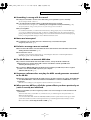
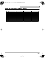
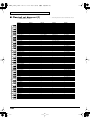
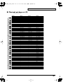
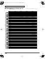
When you need repair service, call your nearest EDIROL/Roland Service Center or authorized EDIROL/Roland distributor
in your country as shown below.
AUSTRALIA
EDIROL Australia Pty. Ltd.
72 Central Avenue
Oak Flats NSW 2529
AUSTRALIA
TEL: (02) 4257 9091
http://www.edirol.com.au
EUROPE
EDIROL (Europe) Ltd.
BRAZIL
HUNGARY
Tom Lee Music Co., Ltd.
Service Division
Roland Brasil Ltda
Intermusica Ltd.
Rua San Jose, 780 Sala B
Parque Industrial San Jose
Cotia - Sao Paulo - SP, BRAZIL
TEL: (011) 4615 5666
Warehouse Area ‘DEPO’ Pf.83
H-2046 Torokbalint, HUNGARY
TEL: (23) 511011
22-32 Pun Shan Street, Tsuen
Wan, New Territories,
HONG KONG
TEL: 2415 0911
INDIA
Rivera Digitec (India) Pvt. Ltd.
409, Nirman Kendra Mahalaxmi
Flats Compound Off. Dr. Edwin
Moses Road, Mumbai-400011,
INDIA
TEL: (022) 498 3079
INDONESIA
PT Citra IntiRama
Deutschland
TEL: 0700 33 47 65 20
France
TEL: 0810 000 371
Italia
TEL: 02 93778329
J1. Cideng Timur No. 15J-150
Jakarta Pusat
INDONESIA
TEL: (021) 6324170
U. S. A. / CANADA
Cosmos Corporation
EDIROL Corporation North
America
425 Sequoia Drive, Suite 114
Bellingham, WA 98226
U. S. A.
TEL: (360) 594-4276
FAX: (360) 594-4271
http://www.edirol.com/
KOREA
1461-9, Seocho-Dong,
Seocho Ku, Seoul, KOREA
TEL: (02) 3486-8855
MALAYSIA
BENTLEY MUSIC SDN BHD
140 & 142, Jalan Bukit Bintang
55100 Kuala Lumpur,MALAYSIA
TEL: (03) 2144-3333
PHILIPPINES
G.A. Yupangco & Co. Inc.
AFRICA
339 Gil J. Puyat Avenue
Makati, Metro Manila 1200,
PHILIPPINES
TEL: (02) 899 9801
CHILE
Comercial Fancy II S.A.
Roland Ireland
Avenida Rancagua #0330
Providencia Santiago, CHILE
TEL: 56-2-373-9100
Audio House, Belmont Court,
Donnybrook, Dublin 4.
Republic of IRELAND
TEL: (01) 2603501
PERU
ITALY
VIDEO Broadcast S.A.
Portinari 199 (ESQ. HALS)
San Borja, Lima 41
REP. OF PERU
TEL: 51-14-758226
MEXICO
Lilleakerveien 2 Postboks 95
Lilleaker N-0216 Oslo
NORWAY
TEL: 273 0074
Todo Musica S.A.
Cuareim 1844, Montevideo,
URUGUAY, CP11200
TEL: 5982-924-2335
VENEZUELA
Musicland Digital C.A.
Av. Francisco de Miranda,
Centro Parque de Cristal, Nivel
C2 Local 20 Caracas
VENEZUELA
TEL: (02) 285 9218
Piata Libertatii 1,
RO-4200 Gheorgheni
TEL: (066) 164-609
Maison FO - YAM Marcel
ROLAND TAIWAN
ENTERPRISE CO., LTD.
25 Rue Jules Hermann,
Chaudron - BP79 97 491
Ste Clotilde Cedex,
REUNION ISLAND
TEL: 28 29 16
Room 5, 9fl. No. 112 Chung Shan
N.Road Sec.2, Taipei, TAIWAN,
R.O.C.
TEL: (02) 2561 3339
SOUTH AFRICA
THAILAND
That Other Music Shop
(PTY) Ltd.
11 Melle St., Braamfontein,
Johannesbourg
Republic of SOUTH AFRICA
P.O.Box 32918, Braamfontein 2017
Republic of SOUTH AFRICA
TEL: (011) 403 4105
Paul Bothner (PTY) Ltd.
17 Werdmuller Centre Claremont
7700
Republic of SOUTH AFRICA
P.O. Box 23032
Claremont, Cape Town
SOUTH AFRICA, 7735
TEL: (021) 674 4030
ASIA
CHINA
Beijing Xinghai Musical
Instruments Co., Ltd.
6 Huangmuchang Chao Yang
District, Beijing, CHINA
TEL: (010) 6774 7491
Theera Music Co. , Ltd.
330 Verng NakornKasem, Soi 2,
Bangkok 10100, THAILAND
TEL: (02) 2248821
VIETNAM
BELGIUM/HOLLAND/
LUXEMBOURG
Roland Benelux N. V.
Houtstraat 3, B-2260, Oevel
(Westerlo) BELGIUM
TEL: (014) 575811
DENMARK
Roland Scandinavia A/S
Nordhavnsvej 7, Postbox 880,
DK-2100 Copenhagen
DENMARK
TEL: (039)16 6200
Saigon Music
FRANCE
138 Tran Quang Khai St.,
District 1
Ho Chi Minh City
VIETNAM
TEL: (08) 844-4068
Roland France SA
AUSTRALIA/
NEW ZEALAND
NEW ZEALAND
Roland Corporation Ltd.
32 Shaddock Street, Mount Eden,
Auckland, NEW ZEALAND
TEL: (09) 3098 715
CENTRAL/LATIN
AMERICA
Shanghai Xingtong Acoustics
Equipment CO.,Ltd.
ARGENTINA
Rm.1108, No.2240 Pudong South
Road Shanghai, CHINA
TEL: (021) 6873 4123
Florida 656 2nd Floor
Office Number 206A
Buenos Aires
ARGENTINA, CP1005
TEL: (54-11) 4- 393-6057
Instrumentos Musicales S.A.
4, Rue Paul Henri SPAAK,
Parc de l'Esplanade, F 77 462 St.
Thibault, Lagny Cedex FRANCE
TEL: 01 600 73 500
FINLAND
Roland Scandinavia As,
Filial Finland
Lauttasaarentie 54 B
Fin-00201 Helsinki, FINLAND
TEL: (9) 682 4020
GERMANY
Roland Elektronische
Musikinstrumente HmbH.
Oststrasse 96, 22844 Norderstedt,
GERMANY
TEL: (040) 52 60090
GREECE
STOLLAS S.A.
Music Sound Light
JORDAN
AMMAN Trading Agency
Cais Das Pedras, 8/9-1 Dto
4050-465 PORTO
PORTUGAL
TEL: (022) 608 00 60
AUSTRIA
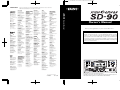
Owner’s Manual
Thank you, and congratulations on your choice of the Edirol SD-90.
8 Retzif Ha’aliya Hashnya St.
Tel-Aviv-Yafo ISRAEL
TEL: (03) 6823666
Tecnologias Musica e Audio,
Roland Portugal, S.A.
ROMANIA
TAIWAN
Halilit P. Greenspoon &
Sons Ltd.
PORTUGAL
EUROPE
REUNION
ISRAEL
UL. Gibraltarska 4.
PL-03664 Warszawa POLAND
TEL: (022) 679 44 19
CRISTOFORI MUSIC PTE
LTD
Siemensstrasse 4, P.O. Box 74,
A-6063 RUM, AUSTRIA
TEL: (0512) 26 44 260
No.41 Nike St.Dr.Shariyati Ave.
Roberoye Cerahe Mirdamad
Tehran, IRAN
TEL: 285 4169
P. P. H. Brzostowicz
SINGAPORE
Roland Austria GES.M.B.H.
MOCO, INC.
POLAND
Al Fanny Trading Office
Blk 3014, Bedok Industrial Park E,
#02-2148, SINGAPORE 489980
TEL: 243 9555
IRAN
NORWAY
Av. Toluca No. 323, Col. Olivar
de los Padres 01780 Mexico D.F.
MEXICO
TEL: (525) 668 04 80
URUGUAY
Radex Sound Equipment Ltd.
17 Diagorou St., P.O. Box 2046,
Nicosia CYPRUS
TEL: (02) 453 426
Viale delle Industrie 8,
20020 Arese, Milano, ITALY
TEL: (02) 937-78300
Roland Scandinavia Avd.
Kontor Norge
Moon Stores
CYPRUS
Roland Italy S. p. A.
Casa Veerkamp, s.a. de c.v.
BAHRAIN
Bab Al Bahrain Road,
P.O. Box 20077
State of BAHRAIN
TEL: 211 005
IRELAND
EGYPT
P.O. Box 2904,
El Horrieh Heliopolos, Cairo,
EGYPT
TEL: (02) 4185531
MIDDLE EAST
Owner’s Manual
Studio 3.4 114 Power Road
London W4 5PY
U. K.
TEL: +44 (0)20 8747 5949
FAX:+44 (0)20 8747 5948
http://www.edirol.com/europe
HONG KONG
Prince Mohammed St. P.O. Box
825 Amman 11118 JORDAN
TEL: (06) 4641200
KUWAIT
Easa Husain Al-Yousifi
Abdullah Salem Street,
Safat KUWAIT
TEL: 5719499
LEBANON
FBS LINES
A. Chahine & Fils
P.O. Box 16-5857 Gergi Zeidan St.
Chahine Building, Achrafieh
Beirut, LEBANON
TEL: (01) 335799
RUSSIA
MuTek
Before using this unit, carefully read the sections entitled: “IMPORTANT
SAFETY INSTRUCTIONS” (Owner’s manual p. 2), “USING THE UNIT
SAFELY” (Owner’s manual p. 3, 4), and “IMPORTANT NOTES” (Owner’s
manual p. 5). These sections provide important information concerning the
proper operation of the unit. Additionally, in order to feel assured that you
have gained a good grasp of every feature provided by your new unit, Owner’s
manual should be read in its entirety. The manual should be saved and kept on
hand as a convenient reference.
QATAR
3-Bogatyrskaya Str. 1.k.l
107 564 Moscow, RUSSIA
TEL: 095 169 5043
Badie Studio & Stores
SPAIN
P.O. Box 62,
DOHA QATAR
TEL: 423554
Roland Electronics
de España, S. A.
SAUDI ARABIA
Calle Bolivia 239, 08020
Barcelona, SPAIN
TEL: (93) 308 1000
aDawliah Universal
Electronics APL
SWEDEN
Roland Scandinavia A/S
SWEDISH SALES OFFICE
Danvik Center 28, 2 tr.
S-131 30 Nacka SWEDEN
TEL: (08) 702 0020
Corniche Road, Aldossary Bldg.,
1st Floor
SAUDI ARABIA
P.O.Box 2154, Alkhobar 31952
SAUDI ARABIA
TEL: (03) 898 2081
SYRIA
SWITZERLAND
Technical Light & Sound
Center
Roland (Switzerland) AG
Musitronic AG
Gerberstrasse 5, Postfach,
CH-4410 Liestal, SWITZERLAND
TEL: (061) 921 1615
Khaled Ibn Al Walid St.
P.O. Box 13520
Damascus - SYRIA
TEL: (011) 2235 384
UKRAINE
TURKEY
TIC-TAC
Barkat Muzik aletleri ithalat
ve ihracat Ltd Sti
Mira Str. 19/108
P.O. Box 180
295400 Munkachevo, UKRAINE
TEL: (03131) 414-40
Siraselviler cad.Guney is hani 8486/6, Taksim. Istanbul. TURKEY
TEL: (0212) 2499324
UNITED KINGDOM
U.A.E.
Roland (U.K.) Ltd.
Atlantic Close, Swansea
Enterprise Park, SWANSEA
SA7 9FJ,
UNITED KINGDOM
TEL: (01792) 700139
Zak Electronics & Musical
Instruments Co. L.L.C.
Zabeel Road, Al Sherooq Bldg.,
No. 14, Grand Floor DUBAI
U.A.E.
TEL: (04) 3360715
155, New National Road
26422 Patras, GREECE
TEL: 061-435400
As of May 15, 2001 (EDIROL-1)
02783801
’01-12-E2-21N
Copyright © 2001 ROLAND CORPORATION
All rights reserved. No part of this publication may be reproduced in any form
without the written permission of ROLAND CORPORATION.
To resize thickness, move all items on the front cover to left or right
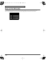
WARNING: To reduce the risk of fire or electric shock, do not expose this apparatus to rain or moisture.
CAUTION
RISK OF ELECTRIC SHOCK
DO NOT OPEN
ATTENTION: RISQUE DE CHOC ELECTRIQUE NE PAS OUVRIR
CAUTION: TO REDUCE THE RISK OF ELECTRIC SHOCK,
DO NOT REMOVE COVER (OR BACK).
NO USER-SERVICEABLE PARTS INSIDE.
REFER SERVICING TO QUALIFIED SERVICE PERSONNEL.
The lightning flash with arrowhead symbol, within an
equilateral triangle, is intended to alert the user to the
presence of uninsulated “dangerous voltage” within the
product’s enclosure that may be of sufficient magnitude to
constitute a risk of electric shock to persons.
The exclamation point within an equilateral triangle is
intended to alert the user to the presence of important
operating and maintenance (servicing) instructions in the
literature accompanying the product.
INSTRUCTIONS PERTAINING TO A RISK OF FIRE, ELECTRIC SHOCK, OR INJURY TO PERSONS.
IMPORTANT SAFETY INSTRUCTIONS
SAVE THESE INSTRUCTIONS
WARNING - When using electric products, basic precautions should always be followed, including the following:
1.
2.
3.
4.
5.
6.
7.
8.
9.
Read these instructions.
Keep these instructions.
Heed all warnings.
Follow all instructions.
Do not use this apparatus near water.
Clean only with a dry cloth.
Do not block any of the ventilation openings. Install in
accordance with the manufacturers instructions.
Do not install near any heat sources such as radiators,
heat registers, stoves, or other apparatus (including
amplifiers) that produce heat.
Do not defeat the safety purpose of the polarized or
grounding-type plug. A polarized plug has two blades with
one wider than the other. A grounding type plug has two
blades and a third grounding prong. The wide blade or the
third prong are provided for your safety. If the provided plug
does not fit into your outlet, consult an electrician for
replacement of the obsolete outlet.
10. Protect the power cord from being walked on or pinched
particularly at plugs, convenience receptacles, and the
point where they exit from the apparatus.
11. Only use attachments/accessories specified
by the manufacturer.
13. Unplug this apparatus during lightning storms or when
unused for long periods of time.
14. Refer all servicing to qualified service personnel. Servicing
is required when the apparatus has been damaged in any
way, such as power-supply cord or plug is damaged, liquid
has been spilled or objects have fallen into the apparatus,
the apparatus has been exposed to rain or moisture, does
not operate normally, or has been dropped.
WARNING:
THIS APPARATUS MUST BE EARTHED
IMPORTANT: THE WIRES IN THIS MAINS LEAD ARE COLOURED IN ACCORDANCE WITH THE FOLLOWING CODE.
GREEN-AND-YELLOW: EARTH, BLUE: NEUTRAL, BROWN: LIVE
As the colours of the wires in the mains lead of this apparatus may not correspond with the coloured markings identifying
the terminals in your plug, proceed as follows:
The wire which is coloured GREEN-AND-YELLOW must be connected to the terminal in the plug which is marked by the
letter E or by the safety earth symbol or coloured GREEN or GREEN-AND-YELLOW.
The wire which is coloured BLUE must be connected to the terminal which is marked with the letter N or coloured BLACK.
The wire which is coloured BROWN must be connected to the terminal which is marked with the letter L or coloured RED.
For the USA
Model Name :
Type of Equipment :
Responsible Party :
Address :
Telephone :
SD-90
USB Audio & MIDI Processing Unit
Edirol Corporation North America
425 Sequoia Drive, Suite 114, Bellingham, WA 98226
(360) 594-4276
This product complies with the requirements of European Directives EMC 89/336/EEC and LVD 73/23/EEC.
For the USA
FEDERAL COMMUNICATIONS COMMISSION
RADIO FREQUENCY INTERFERENCE STATEMENT
This equipment has been tested and found to comply with the limits for a Class B digital device, pursuant to Part 15 of the
FCC Rules. These limits are designed to provide reasonable protection against harmful interference in a residential
installation. This equipment generates, uses, and can radiate radio frequency energy and, if not installed and used in
accordance with the instructions, may cause harmful interference to radio communications. However, there is no guarantee
that interference will not occur in a particular installation. If this equipment does cause harmful interference to radio or
television reception, which can be determined by turning the equipment off and on, the user is encouraged to try to correct the
interference by one or more of the following measures:
– Reorient or relocate the receiving antenna.
– Increase the separation between the equipment and receiver.
– Connect the equipment into an outlet on a circuit different from that to which the receiver is connected.
– Consult the dealer or an experienced radio/TV technician for help.
This device complies with Part 15 of the FCC Rules. Operation is subject to the following two conditions:
(1) This device may not cause harmful interference, and
(2) This device must accept any interference received, including interference that may cause undesired operation.
Unauthorized changes or modification to this system can void the users authority to operate this equipment.
This equipment requires shielded interface cables in order to meet FCC class B Limit.
For Canada
NOTICE
This Class B digital apparatus meets all requirements of the Canadian Interference-Causing Equipment Regulations.
AVIS
Cet appareil numérique de la classe B respecte toutes les exigences du Règlement sur le matériel brouilleur du Canada.
For the U.K.
DECLARATION OF CONFORMITY
Compliance Information Statement
For EU Countries
sd90_manual_e.book 3 ページ 2004年10月4日 月曜日 午後3時28分
USING THE UNIT SAFELY
The
symbol alerts the user to important instructions
or warnings.The specific meaning of the symbol is
determined by the design contained within the
triangle. In the case of the symbol at left, it is used for
general cautions, warnings, or alerts to danger.
Used for instructions intended to alert
the user to the risk of death or severe
injury should the unit be used
improperly.
Used for instructions intended to alert
the user to the risk of injury or material
damage should the unit be used
improperly.
* Material damage refers
other adverse effects
respect to the home
furnishings, as well
animals or pets.
to damage or
caused with
and all its
to domestic
001
• Before using this unit, make sure to read the
instructions below, and the Owner’s Manual.
................................................................................................
002a
• Do not open or perform any internal modifications on the unit.
................................................................................................
003
• Do not attempt to repair the unit, or replace
parts within it (except when this manual
provides specific instructions directing you
to do so). Refer all servicing to your retailer,
the nearest Roland / EDIROL Service Center,
or an authorized Roland distributor, as listed
on the "Information" page.
................................................................................................
004
• Never use or store the unit in places that are:
• Subject to temperature extremes (e.g., direct
sunlight in an enclosed vehicle, near a
heating duct, on top of heat-generating
equipment); or are
• Damp (e.g., baths, washrooms, on wet floors); or are
• Humid; or are
• Exposed to rain; or are
• Dusty; or are
• Subject to high levels of vibration.
................................................................................................
007
The
symbol alerts the user to items that must never
be carried out (are forbidden). The specific thing that
must not be done is indicated by the design contained
within the circle. In the case of the symbol at left, it
means that the unit must never be disassembled.
• Make sure you always have the unit placed
so it is level and sure to remain stable. Never
place it on stands that could wobble, or on
inclined surfaces.
The ● symbol alerts the user to things that must be
carried out. The specific thing that must be done is
indicated by the design contained within the circle. In
the case of the symbol at left, it means that the powercord plug must be unplugged from the outlet.
8a
00
• The unit should be connected to a power
supply only of the type described in the
operating instructions, or as marked on the
unit.
................................................................................................
009
• Do not excessively twist or bend the power
cord, nor place heavy objects on it. Doing so
can damage the cord, producing severed
elements and short circuits. Damaged cords
are fire and shock hazards!
................................................................................................
010
• This unit, either alone or in combination with
an amplifier and headphones or speakers,
may be capable of producing sound levels
that could cause permanent hearing loss. Do
not operate for a long period of time at a high
volume level, or at a level that is uncomfortable. If you experience any hearing loss or
ringing in the ears, you should immediately
stop using the unit, and consult an audiologist.
................................................................................................
011
• Do not allow any objects (e.g., flammable
material, coins, pins); or liquids of any kind
(water, soft drinks, etc.) to penetrate the unit.
................................................................................................
013
• In households with small children, an adult
should provide supervision until the child is
capable of following all the rules essential for
the safe operation of the unit.
................................................................................................
014
• Protect the unit from strong impact.
(Do not drop it!)
3
sd90_manual_e.book 4 ページ 2004年10月4日 月曜日 午後3時28分
015
• Do not force the unit’s power-supply cord to
share an outlet with an unreasonable number
of other devices. Be especially careful when
using extension cords—the total power used
by all devices you have connected to the
extension cord’s outlet must never exceed the
power rating (watts/amperes) for the
extension cord. Excessive loads can cause the
insulation on the cord to heat up and
eventually melt through.
................................................................................................
110a
• Whenever you suspect the possibility of
lightning in your area, pull the plug on the
power cord out of the outlet.
................................................................................................
118
• Should you remove the optical connector
caps, make sure to put them in a safe place
out of children's reach, so there is no chance
of them being swallowed accidentally.
................................................................................................
016
• Before using the unit in a foreign country,
consult with your retailer, the nearest Roland
Service Center, or an authorized Roland
distributor, as listed on the "Information"
page.
................................................................................................
023
• DO NOT play a CD-ROM disc on a conventional audio CD player. The resulting sound
may be of a level that could cause permanent
hearing loss. Damage to speakers or other
system components may result.
101a
• The unit should be located so that its location
or position does not interfere with its proper
ventilation.
................................................................................................
Copyright
102b
• Always grasp only the plug on the powersupply cord when plugging into, or
unplugging from, an outlet or this unit.
................................................................................................
104
• Try to prevent cords and cables from
becoming entangled. Also, all cords and
cables should be placed so they are out of the
reach of children.
................................................................................................
106
• Never climb on top of, nor place heavy
objects on the unit.
................................................................................................
107b
• Never handle the power cord or its plugs
with wet hands when plugging into, or
unplugging from, an outlet or this unit.
................................................................................................
108a
• Before moving the unit, disconnect the power
plug from the outlet, and pull out all cords
from external devices.
................................................................................................
109a
• Before cleaning the unit, turn off the power
and unplug the power cord from the outlet.
4
205
* Microsoft and Windows are registered trademarks
of Microsoft Corporation.
206c
* Windows® 98 is known officially as: “Microsoft®
Windows® 98 operating system.”
add
* Windows® Me is known officially as: “Microsoft®
Windows® Millennium Edition operating system.”
206f
* Windows® 2000 is known officially as: “Microsoft®
Windows® 2000 operating system.”
207
* Apple and Macintosh are registered trademarks of
Apple Computer, Inc.
* MacOS is a trademark of Apple Computer, Inc.
207
* OMS is a registered trademark of Opcode Systems,
Inc.
* GS (
) is a registered trademark of Roland
Corporation.
add
* XG (
) and XGlite (
YAMAHA Corporation.
) are trademarks of
220
* All product names mentioned in this document are
trademarks or registered trademarks of their
respective owners.
sd90_manual_e.book 5 ページ 2004年10月4日 月曜日 午後3時28分
IMPORTANT NOTES
In addition to the items listed under “IMPORTANT SAFETY INSTRUCTIONS” and “USING THE UNIT
SAFELY” on pages 3 and 4, please read and observe the following:
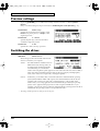
Power Supply
301
• Do not use this unit on the same power circuit with
any device that will generate line noise (such as an
electric motor or variable lighting system).
• Before connecting this unit to other devices, turn off
the power to all units. This will help prevent
malfunctions and/or damage to speakers or other
devices.
307
Placement
351
• Using the unit near power amplifiers (or other
equipment containing large power transformers)
may induce hum. To alleviate the problem, change
the orientation of this unit; or move it farther away
from the source of interference.
• This device may interfere with radio and television
reception. Do not use this device in the vicinity of
such receivers.
352
354a
• Do not expose the unit to direct sunlight, place it
near devices that radiate heat, leave it inside an
enclosed vehicle, or otherwise subject it to temperature extremes. Excessive heat can deform or
discolor the unit.
• To avoid possible breakdown, do not use the unit in
a wet area, such as an area exposed to rain or other
moisture.
559a
• When you need to transport the unit, package it in
the box (including padding) that it came in, if
possible. Otherwise, you will need to use equivalent
packaging materials.
• Use a cable from Roland to make the connection. If
using some other make of connection cable, please
note the following precautions.
• Some connection cables contain resistors. Do not
use cables that incorporate resistors for
connecting to this unit. The use of such cables can
cause the sound level to be extremely low, or
impossible to hear. For information on cable
specifications, contact the manufacturer of the
cable.
• Unauthorized duplication, reproduction, hiring, and
lending prohibited.
562
\563
Handling CD-ROMs
801
• Avoid touching or scratching the shiny underside
(encoded surface) of the disc. Damaged or dirty CDROM discs may not be read properly. Keep your
discs clean using a commercially available CD
cleaner.
355
Maintenance
401a
• For everyday cleaning wipe the unit with a soft, dry
cloth or one that has been slightly dampened with
water. To remove stubborn dirt, use a cloth impregnated with a mild, non-abrasive detergent. Afterwards, be sure to wipe the unit thoroughly with a
soft, dry cloth.
• Never use benzine, thinners, alcohol or solvents of
any kind, to avoid the possibility of discoloration
and/or deformation.
402
Additional Precautions
553
• Use a reasonable amount of care when using the
unit’s buttons, sliders, or other controls; and when
using its jacks and connectors. Rough handling can
lead to malfunctions.
• Never strike or apply strong pressure to the display.
• A small amount of noise may be heard from the
display during normal operation.
• When connecting / disconnecting all cables, grasp
the connector itself—never pull on the cable. This
way you will avoid causing shorts, or damage to the
cable’s internal elements.
• A small amount of heat will radiate from the unit
during normal operation.
• To avoid disturbing your neighbors, try to keep the
unit’s volume at reasonable levels. You may prefer
to use headphones, so you do not need to be
concerned about those around you (especially when
it is late at night).
554
555
556
557
558a
Copyright
851
• Unauthorized recording, distribution, sale, lending,
public performance, broadcasting, or the like, in
whole or in part, of a work (musical composition,
video, broadcast, public performance, or the like)
whose copyright is held by a third party is
prohibited by law.
• When exchanging audio signals through a digital
connection with an external instrument, this unit can
perform recording without being subjected to some
of the restrictions of the Serial Copy Management
System (SCMS). This is because the unit is intended
solely for musical production, and is designed not to
be subject to restrictions as long as it is used to
record works (such as your own compositions) that
do not infringe on the copyrights of others. (SCMS is
a feature that prohibits second-generation and later
copying through a digital connection. It is built into
MD recorders and other consumer digital-audio
equipment as a copyright-protection feature.)
• Do not use this unit for purposes that could infringe
on a copyright held by a third party. Roland
assumes no responsibility whatsoever with regard to
any infringements of third-party copyrights arising
through your use of this unit.
• The explanations in this manual include illustrations
that depict what should typically be shown by the
display. Note, however, that your unit may incorporate a newer, enhanced version of the system (e.g.,
includes newer sounds), so what you actually see in
the display may not always match what appears in
the manual.
852b
853
985
5
sd90_manual_e.book 6 ページ 2004年10月4日 月曜日 午後3時28分
Contents
USING THE UNIT SAFELY....................................................... 3
IMPORTANT NOTES ................................................................ 5
Introduction .............................................................................. 9
How to read this manual .................................................................................................... 9
Main features ........................................................................................................................ 9
Names of things and what they do ................................................................................. 10
Front Panel............................................................................................................... 10
Rear Panel ................................................................................................................ 12
Basic operation ...................................................................... 13
How the SD-90 is organized............................................................................................. 13
Operations in the basic screen.......................................................................................... 14
Listening to the internal demo songs................................................................... 14
Auditioning the sounds (Preview)....................................................................... 15
Adjusting the brightness of the display (Contrast)............................................ 16
Using the internal sound generator ..................................... 17
About the sound generator modes.................................................................................. 17
About GM2/Native modes .............................................................................................. 18
GM2/Native mode sound sets ............................................................................. 18
About parts and sounds.................................................................................................... 19
Different types of part............................................................................................ 19
Polyphony and voices ............................................................................................ 19
Switching the sound generator mode ............................................................................. 20
Selecting a part ................................................................................................................... 21
Selecting the type of part (INST/DRUM) ...................................................................... 22
Selecting the sound set ...................................................................................................... 23
Selecting a sound................................................................................................................ 24
Selecting a drum set........................................................................................................... 25
Muting/soloing a part....................................................................................................... 26
Muting a part........................................................................................................... 26
Soloing a part........................................................................................................... 27
About parameters .............................................................................................................. 28
Editing the parameters ...................................................................................................... 29
Editing part parameters......................................................................................... 29
Editing in the list display....................................................................................... 30
Editing parameters that are common to all parts .............................................. 31
About parameters that can be edited from the SD-90’s panel..................................... 32
Part parameters (GM2 mode, Native mode) ...................................................... 32
Part parameters (Native mode) ............................................................................ 36
Parameters common to all parts (GM2 mode, Native mode) .......................... 37
6
sd90_manual_e.book 7 ページ 2004年10月4日 月曜日 午後3時28分
Contents
Using the effects of the internal sound generator.............. 38
About the sound generator effects .................................................................................. 38
Editing the sound generator effects................................................................................. 39
Parameters that can be edited in GM2 mode................................................................. 40
Reverb (System Effect) ........................................................................................... 40
Chorus (System Effect)........................................................................................... 40
EQ (Equalizer) ......................................................................................................... 41
Parameters that can be edited in Native mode.............................................................. 42
Reverb (System Effect) ........................................................................................... 42
Chorus (System Effect)........................................................................................... 44
MFX (Multi-effects) ................................................................................................ 45
EQ (Equalizer) ......................................................................................................... 47
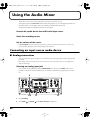
Using the Audio Mixer ........................................................... 48
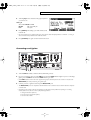
Connecting an input source audio device ...................................................................... 48
Analog connections ................................................................................................ 48
Digital connections ................................................................................................. 50
Selecting the recording source ......................................................................................... 52
Selecting a routing .................................................................................................. 52
Setting the volume of the source sound ......................................................................... 53
Editing in the Icon display .................................................................................... 54
Editing in the List display ..................................................................................... 54
Audio mixer parameter list ................................................................................... 55
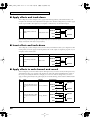
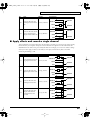
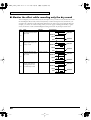
About the routing presets ................................................................................................. 57
Basic routing............................................................................................................ 57
Record the dry sound (Default Source Recording)............................................ 57
Apply effects and track-down .............................................................................. 58
Insert effects and track-down ............................................................................... 58
Apply effects to each channel and record ........................................................... 58
Apply effects and record a single channel .......................................................... 59
Monitor the effect while recording only the dry sound.................................... 60
Using the audio effects ......................................................... 61
Select the location of the effect (Mixer Routing)............................................................ 61
Selecting the type of effect (Algorithm).......................................................................... 62
Editing the effect ................................................................................................................ 63
Editing in the icon display..................................................................................... 63
Editing in the list display....................................................................................... 64
Bypassing the effect................................................................................................ 64
About the effect algorithms .............................................................................................. 65
Space Multi .............................................................................................................. 65
Guitar Multi............................................................................................................. 65
Vocal/Bass Multi .................................................................................................... 65
Groove Multi ........................................................................................................... 65
Isolator...................................................................................................................... 66
Center Canceller...................................................................................................... 66
Lo-Fi Processor........................................................................................................ 66
Surround RV (Surround Reverb) ......................................................................... 66
Mastering ................................................................................................................. 68
7
sd90_manual_e.book 8 ページ 2004年10月4日 月曜日 午後3時28分
Contents
System-related settings ........................................................ 69
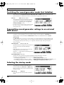
Switching the sound generator mode (Inst Initialize) .................................................. 70
Transmitting sound generator settings to an external MIDI device........................... 70
Selecting the startup mode ............................................................................................... 70
USB mode ................................................................................................................ 71
MIDI mode .............................................................................................................. 71
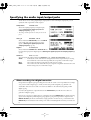
Specifying the start-up sound generator mode ............................................................. 72
Setting the Device ID Number ......................................................................................... 72
Transmitting button/knob operations to an external MIDI device ........................... 72
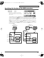
Specifying the function of the MIDI connectors............................................................ 73
Preview settings ................................................................................................................. 74
Switching the driver .......................................................................................................... 74
Specifying the audio input/output jacks ....................................................................... 75
Adjusting the contrast of the display .............................................................................. 76
Setting the system tempo .................................................................................................. 76
Restoring the factory settings........................................................................................... 76
Controlling the SD-90 via MIDI.............................................. 77
Controlling the internal sound generator....................................................................... 77
Switching the sound generator mode.................................................................. 77
Switching the sound set ......................................................................................... 79
Switching the type of part ..................................................................................... 80
Switching sounds.................................................................................................... 82
Switching the drum set .......................................................................................... 85
Editing MIDI effect parameters ............................................................................ 87
Writing/loading SD-90 settings ........................................................................... 93
Controlling the audio mixer ............................................................................................. 95
Switching the routing............................................................................................. 95
Editing mixer parameters ...................................................................................... 95
Editing audio effect parameters ........................................................................... 96
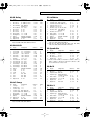
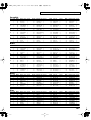
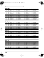
Appendices............................................................................. 97
Troubleshooting ................................................................................................................. 97
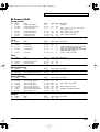
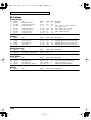
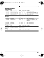
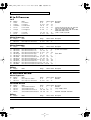
Part parameter list............................................................................................................ 101
Effect parameter list......................................................................................................... 102
MFX parameter list .......................................................................................................... 105
AFX parameter list ........................................................................................................... 120
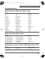
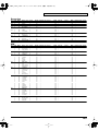
Instrument list (GM2 / Native mode) .......................................................................... 129
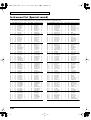
Instrument list (Special sound) ...................................................................................... 134
Instrument list (GS mode)............................................................................................... 135
Instrument list (XGlite mode) ........................................................................................ 137
Drum set list (GM2 / Native mode).............................................................................. 139
Drum set list (GS mode).................................................................................................. 148
Drum set list (XGlite mode)............................................................................................ 151
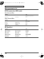
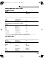
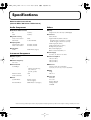
Specifications....................................................................... 159
INDEX .................................................................................... 160
8
sd90_manual_e.book 9 ページ 2004年10月4日 月曜日 午後3時28分
Introduction
Thank you, and congratulations on your choice of the Edirol SD-90 Studio Canvas.
The SD-90 is a cutting-edge, desktop studio system which contains a MIDI sound generator with a treasure
chest of sounds that will stimulate your creativity, plus a 24-bit/48 kHz audio interface. It’s the ideal partner
for your music-making.
How to read this manual
The documentation for the SD-90 consists of a Startup Manual, a User Guide, and Additional Information
(PDF) on the included CD-ROM.
• The Startup Manual takes you through the steps you need to follow in order to get ready to use the
SD-90 with your computer. Please read this first.
• The User Guide explains how to use all the basic features of the SD-90. After you have made settings
for the SD-90 as described in the Startup Manual, and have verified that it produces sound correctly,
refer to the User Guide as necessary, depending on the purpose you have in mind.
• Additional Information explains various settings you can make in order to take full advantage of the
SD-90’s functionality. Read this material as necessary. In order to read the Additional Information
PDF file, you will need the Adobe Acrobat Reader. The most recent version of the Adobe Acrobat
Reader can be downloaded from the Adobe Systems Incorporated website.
(http://www.adobe.com/)
• Letters and numbers enclosed in [ ] indicate buttons on the panel of the SD-90.
• Areas enclosed by a gray rectangular frame contain supplementary explanations for a function, or tips
for operation.
• If the SD-90 does not operate as you expect, refer to "Troubleshooting" (p. 97).
Main features
Richly expressive pro-quality sounds
The 32-part/128-voice MIDI sound generator section features three MFX (multi-effect) units in addition to
reverb, chorus, and equalizer. More than a thousand sounds using pro-quality wave data are organized into
four categories, providing unlimited creative potential.
Cutting-edge desktop studio system
In full-digital form, the SD-90 combines a MIDI sound generator, audio mixer, and audio effects—everything
you need for music production. The SD-90 is all you need to set up a cutting-edge desktop studio.
A full array of audio multi-effects
The audio interface lets you input a mic/guitar/CD or other audio source into your computer, and it also
provides audio effects that can be applied to the internal sound generator as well. A total of nine algorithms
are provided, including mastering effects for use during mixdown, as well as “surround reverb,” which
supports multi-channel speaker systems, allowing you to use the effects that are most suitable for your output
needs.
Easy operation
The front panel features a large display and three rotary encoders, letting you select sounds/effects and edit
parameters easily and intuitively.
WDM/ASIO™ 2.0 compatible drivers included
You can enjoy high performance when used with WDM-compatible applications such as Sonar™ and
ASIO™-compatible applications such as Cubase™ or Logic™. Of course, the SD-90 can also be used with
applications compatible with MME (Windows®) .
9
sd90_manual_e.book 10 ページ 2004年10月4日 月曜日 午後3時28分
Introduction
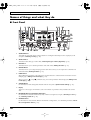
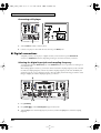
Names of things and what they do
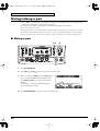
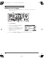
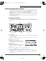
■ Front Panel
fig.1-01
1
2
34 5 6
7
8 9
10
11
12
13
14
15
16 17 18 19
21
22
1
SOURCE Buttons
These buttons recall audio mixer routings suitable for sending the selected input source (input jack) to the
computer. ("Selecting a routing" (p. 52))
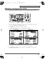
2
SELECT Button
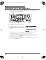
This button selects the type of audio effect ("Selecting the type of effect (Algorithm)" (p. 62)).
3
EDIT Button
This button allows you to edit the parameters of the audio effect ("Editing the effect" (p. 63)).
4
BYPASS Button
This button allows you to temporarily bypass the audio effect so that you can compare the sound with and
without the effect ("Editing the effect" (p. 63)).
5
PAGE Buttons
When editing the parameters of the audio mixer, use these buttons to switch between screens that consist of
multiple pages ("Editing in the List display" (p. 54)).
When you press [
] and [
List display" (p. 54)).
10
20
] simultaneously, a list of the parameters will be displayed ("Editing in the
6
SYSTEM Button
Use this button to make settings that affect the entire SD-90 system ("System-related settings" (p. 69)).
7
Display
This shows various types of information (such as level meters or parameter values) related to the current
state.
8
INST/DRUM SET (Instrument/Drum Set) Button
Use this button to select the instrument (sound) or drum set assigned to each part. ("Selecting a sound" (p.
24), "Selecting a drum set" (p. 25))
9
EFFECTS Button
Use this button to select an effect (MFX) for the internal sound generator, or to edit effect parameters ("About
the sound generator effects" (p. 38)).
sd90_manual_e.book 11 ページ 2004年10月4日 月曜日 午後3時28分
Introduction
10 PART Buttons
Use these buttons to switch the part display.
If you press [
] and [
] simultaneously, all parameters will be displayed ("Editing parameters that are
common to all parts" (p. 31)).
11 EXIT Button
Use this button to cancel an operation, or to return to the previous screen or the basic screen.
12 ENTER Button
Use this button to execute an operation or to select a screen.
13 PREVIEW Button
Use this button to audition the currently selected sound (instrument) ("Auditioning the sounds (Preview)"
(p. 15).
14 SHIFT Button
This button is used in conjunction with other buttons to change the function of the other button.
fig.1-01a
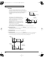
15 POWER Switch
This turns the power of the SD-90 on/off. The power is on when the
switch is pressed in, and the power is off when the switch is in the
outward position. When the power is on, the white backlighting of
the LCD screen will also be on.
Lower position
Upper position
ON
OFF
16 MIC/GUITAR Jack
A dynamic microphone or a guitar can be connected here ("Connecting a mic/guitar" (p. 49)).
* This jack is not compatible with the miniature microphones (condenser mics) included with personal computers
and sound cards.
17 GAIN Knob
Turning this knob will adjust the gain of the signal input from the MIC/GUITAR jack or LINE IN jacks. By
pressing this knob, you can select whether a mic or a guitar is connected to the MIC/GUITAR jack
("Connecting a mic/guitar" (p. 49)).
18 GAIN Indicator
This indicates whether mic or guitar is selected for the MIC/GUITAR jack. Mic is selected when the indicator is
lit, and guitar is selected when the indicator is dark.
19 PEAK Indicator
This indicates the level of the signal that is input to the MIC/GUITAR jack or the LINE IN jacks. The indicator
will light at -3 dB, so use the GAIN knob to adjust the input so that the indicator lights occasionally during the
loudest passages.
20 QUICK ACCESS Knobs
In the basic screen, these knobs adjust the volume levels of the following outputs ("Adjusting the volume in
the main screen" (p. 13)).
In the editing screens, the parameters shown in the bottom row of the display are assigned to these knobs,
and can be adjusted by them.
21 VOLUME Knob
This knob adjusts the output level of the audio signal that is output from the rear panel OUTPUT 1 jacks and
from the Headphone jack
.
22 Headphone Jack
A set of headphones can be connected to this jack. The headphone jack outputs the same signal as the
OUTPUT 1 jacks.
11
sd90_manual_e.book 12 ページ 2004年10月4日 月曜日 午後3時28分
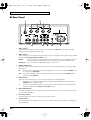
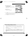
Introduction
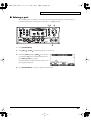
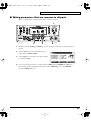
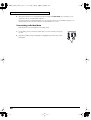
■ Rear Panel
fig.1-02
1
2
3
4
5
6
7
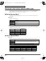
1
USB Connector
A USB cable can be used to connect the SD-90 to your computer. In USB mode, audio signals and MIDI
messages can be exchanged through this cable.
2
MIDI Connectors
These connectors can be connected to other MIDI devices, such as a sequencer, allowing the exchange of MIDI
messages ("Controlling the SD-90 via MIDI" (p. 77)).
IN1/IN2:
These connectors receive MIDI messages from other devices. The received MIDI messages are
sent to the computer (in USB mode) or to the internal sound generator (in MIDI mode).
OUT1/OUT2: These connectors transmit MIDI messages to other devices.
3
DIGITAL AUDIO Jacks
These jacks can be connected to digital audio devices such as CD players and MD players to transfer digital
audio signals.
IN:
These jacks receive digital signals from other digital devices. Use a coaxial cable with COAXIAL, and
an optical cable with OPTICAL.
OUT: These jacks send digital signals to other digital devices. Use a coaxial cable with COAXIAL, and an
optical cable with OPTICAL.
4
OUTPUT Jacks
These jacks output audio signals to your audio playback system or amplified speakers.
1:
These jacks always output the signals that are being input at the input jacks. Use the front panel
VOLUME knob to adjust the volume.
2:
These jacks output either the signal for the rear speakers of surround reverb, or the signal from the
internal sound generator ("Using surround output" (p. 67)).
12
5
INPUT (LINE IN) Jacks
These jacks accept the input of analog audio signals from an audio device such as a CD player or MD player,
or from another MIDI device.
6
Grounding Terminal
This prevents the panel surface from developing an electrical charge.
7
AC IN Connector
Connect the supplied AC cord here. Never use any AC cord other than the one provided, since doing so may
cause malfunction.
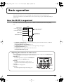
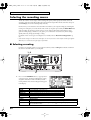
sd90_manual_e.book 13 ページ 2004年10月4日 月曜日 午後3時28分
Basic operation
This section introduces you to the overall design and organization the SD-90, and explains basic
operation. Please make sure to read this section, since it is sure to help you gain a better understanding of
your new unit.
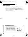
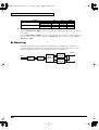
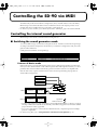
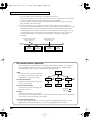
How the SD-90 is organized
The SD-90 consists of the following three blocks. For details on each block, refer to the corresponding
page.
fig.2-01
SD-90
MIDI messages
from the USB connector
Audio signals
from the USB connector
Digital IN jack
MIDI sound
generator
Routes to the computer
via USB connector
Audio
Mixer
OUTPUT jacks
Digital OUT jack
MIC/GUITAR/LINE IN
Audio
effects
• The internal sound generator, which receives MIDI messages from the USB connector (or MIDI IN
connectors) and produces sound
->"Using the internal sound generator" (p. 17)
• The audio mixer, which determines the flow of audio signal inputs and outputs
->"Using the Audio Mixer" (p. 48)
• The effect block, which applies effects to all audio sources
->"Using the audio effects" (p. 61)
Adjusting the volume in the main screen
In the main screen (the screen that appears immediately after you turn on the power), the [V1]–[V3] knobs
and the [VOLUME] knob will adjust the volume of each block.
fig.dummy
[VOLUME] knob:
The audio signal that is output from the Headphone
jack and the rear panel OUTPUT 1 jacks
[V1] knob:
The digital audio signal that is sent from your
computer via the USB cable and input to the SD-90
[V2] knob:
The internal sound generator
[V3] knob:
The audio signal that is input at the analog jacks
13
sd90_manual_e.book 14 ページ 2004年10月4日 月曜日 午後3時28分
Basic operation
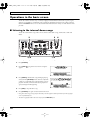
Operations in the basic screen
The SD-90 contains a diverse array of sounds, ranging from instrumental sounds such as piano/organ/
guitar for an ensemble, to sound effects such as birdsong and telephone ringers. Each of these sounds is
called an instrument. Here’s how to select instruments and listen to the variety of sounds that the SD-90
provides.
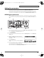
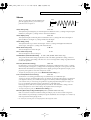
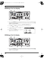
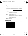
■ Listening to the internal demo songs
The SD-90 contains demo songs. Here’s how to listen to these demo songs, and hear the sounds and
effects.
fig.2-05
3
2, 6
1.
2.
5
4
1, 4
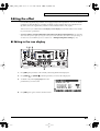
Turn the [VOLUME] knob fully counterclockwise (minimum setting).
Press [SYSTEM].
fig.2-05a
3.
Press [PAGE
appear.
] to get the screen shown at right to
fig.2-05b
4.
Press [ENTER], and the demo song will begin playing.
Slowly turn the [VOLUME] knob clockwise to adjust the
volume to a comfortable level. Once the demo song has
played to the end, it will automatically be played over
again, starting from the beginning.
5.
Press [EXIT] to stop the demo song.
6.
Press [SYSTEM] once again to return to the main screen.
*
*
14
Using these demo songs for any purpose other than personal enjoyment without permission from the copyright
owner is prohibited by law.
The demo song playback data will not be output from the MIDI OUT jacks.
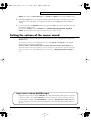
sd90_manual_e.book 15 ページ 2004年10月4日 月曜日 午後3時28分
Basic operation
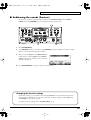
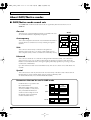
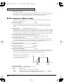
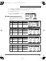
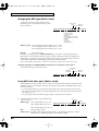
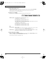
■ Auditioning the sounds (Preview)
On the SD-90, sounds are specified using two numbers: the instrument number and the variation
number. By pressing [PREVIEW] you can audition the currently selected sound.
fig.2-03a
1, 4
3
2
1.
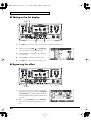
Press [INST/DRUM SET].
2.
Press [PREVIEW]. While you continue pressing [PREVIEW], the button will light and a phrase will play.
When you release the button, the phrase will stop.
fig.dummy
3.
When you turn the [V1] knob, the capital sound will
change. When you turn the [V2] knob, the variation
sound will change. Try selecting various sounds and
listening to the phrases.
4.
Press [INST/DRUM SET] once again to return to the main screen.
Changing the Preview settings
At the factory settings, you can audition a characteristic phrase that uses the currently selected sound
(Phrase Preview). Alternatively, you can set it so that Preview will play a single note at the pitch (key)
and strength (velocity) that you specify.
For details on Preview settings, refer to "Preview settings" (p. 74).
15
sd90_manual_e.book 16 ページ 2004年10月4日 月曜日 午後3時28分
Basic operation
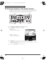
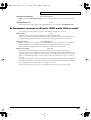
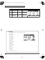
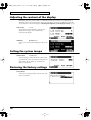
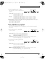
■ Adjusting the brightness of the display (Contrast)
Immediately after the power is turned on, or after the SD-90 has been used for an extended period, or
depending on the conditions in which it is placed, the characters or icons in the display screen may
become difficult to read. If this happens, you can adjust the contrast of the display.
fig.2-02
2
4
3
1, 5
1.
Press [SYSTEM].
2.
Press [PAGE
3.
] or [PAGE
] until LCD Contrast is displayed.
Turn the [V3] knob to adjust the contrast of the display.
fig.2-03
LCD Contrast 1–5–8
Adjusts the contrast of the display.
fig.7-1ga
LCD Mode
Normal, Invert
Adjusts the contrast of the display.
16
4.
Press [ENTER]. The contrast setting you specify will be remembered by the SD-90.
* Do not turn off the power while the setting is being stored (while “(TBD)” is displayed). Doing so will cause all
data stored in the SD-90 to be lost.
5.
Once again press [SYSTEM] to return to the main screen.
sd90_manual_e.book 17 ページ 2004年10月4日 月曜日 午後3時28分
Using the internal sound generator
The SD-90 contains a sound generator with 1,050 diverse and high-quality sounds. The internal sound
generator has four modes to support different sound generator formats, and you can select the mode you
want to use. For details on the sound generator modes, refer to "About the sound generator modes" (p.
17).
Multi-effect, chorus, reverb, and equalizer (a total of four effects units) are also built-in, letting you apply
effects to the internal sound generator. For details on the effects, refer to "Using the effects of the
internal sound generator" (p. 38).
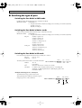
About the sound generator modes
The SD-90 has four sound generator modes: GM2, Native, GS, and XGlite.
GM2 mode further consists of four sound sets, and Native mode consists of six sound sets. For details on
the Native sound sets, refer to "GM2/Native mode sound sets" (p. 18).
GM2 mode
This sound generator mode is compatible with the “GM2” sound generator format.
GM2 is “recommended practice,” and it is backwardly compatible with GM. It was created in order to
allow more sophisticated performance expression and greater compatibility. It includes detailed
definitions concerning sound editing and the use of effects (things that weren’t covered by the earlier GM
format), and it also expands the sound set. GM2-compatible sound generators will correctly play back
music data bearing either the GM or GM2 logos.
When it is necessary to make a distinction, this manual will sometimes refer to “GM1” to indicate the
earlier GM format which does not include the extended specifications of GM2.
Native mode
This is the sound generator mode that allows you to take advantage of the SD-90’s full potential.
It uses the same instrument files and sound sets as GM2 mode, and provides a greater number of editable
parameters.
In addition, it provides two special sound sets that collect the most distinctive of the sounds of the SD-90.
GS mode
This sound generator mode supports the “GS” sound generator format promoted by Roland Corporation.
In addition to the General MIDI functionality, this format expands the sound set, and also enhances
compatibility by providing detailed specifications for functionality such as sound editing and effects
(reverb and chorus). For flexibility in meeting future needs, it also provides for the addition of new
sounds and expanded functionality. Since the GS format is compatible with GM, it allows GM scores to be
played in the same way as GS music data (music data created in conformity with the GS format).
*
It is not possible to edit GS mode sound generator parameters from the panel of the SD-90.
XGlite mode
XG is a sound generator format promoted by Yamaha Corporation, which is based on GM1 (General
MIDI 1). It provides detailed specifications concerning expansion of the sound sets, editing methods, and
effects structures and types.
XGlite is a reduced-functionality (“lite”) version of XG, which allows simple playback of XG music data
on a sound generator bearing the XGlite logo. Since XGlite has some limitations on the parameters and
effects that can be controlled, the XG music data may sound different than the original data.
*
It is not possible to edit XGlite mode sound generator parameters from the panel of the SD-90.
17
sd90_manual_e.book 18 ページ 2004年10月4日 月曜日 午後3時28分
Using the internal sound generator
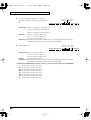
About GM2/Native modes
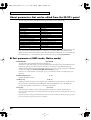
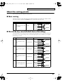
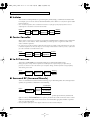
■ GM2/Native mode sound sets
The sounds sets of GM2 mode and Native mode are organized by their character into four or six
variations.
fig.5-01
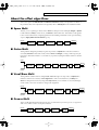
Classical
This is the basic sound set that blends well into an ensemble. This set is
also used when GM2 data compatibility is important.
Contemporary
This sound set emphasizes the realism of each individual instrument. It
contains numerous sounds that use velocity switching for expressive
dynamics.
SD-90
GM2
Native
Classical
Classical
Contemporary
Contemporary
Solo
Solo
Enhanced
Enhanced
Solo
Special 1
This sound set contains mainly sounds that are designed to be
distinctive when used to play solos. These sounds include spacious
stereo-sampled sounds, as well as sounds that are switched by velocity.
Special 2
GS
XGlite
Enhanced
This sound set concentrates on sounds that are designed with multi-effects (MFX), such as distortion
guitar and rotary organ. You can obtain an effect simply by selecting one of these sounds. The set also
includes acoustic instruments with a clear upper register produced by equalization processing, and synth
sounds based on multi-effects.
Up to three enhanced sounds can be used simultaneously. This set also contains some sounds that do not
use MFX.
Special
This sound set can be used only in Native mode. It consists mainly of the best sounds of the SD-90 from
the Enhanced set, and also includes highly original sounds not defined by GM2.
As with the Enhanced set, most sounds use multi-effects (MFX).
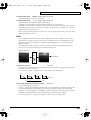
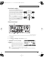
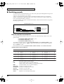
Parameters that can be used in GM2 mode
fig.5-01a
In GM2 mode it is not possible to edit
the sounds themselves.
Multi-effects (MFX) and the sounds
are always handled as a unit, and are
always included in the Enhanced
sound set. (In the example shown in
the diagram at right, an Enhanced
sound is selected for Part 2.)
18
Part 1
Sounds
Part 2
Sounds
Part 32
Sounds
Part
Parameters
MFX
Part
Parameters
Part
Parameters
sd90_manual_e.book 19 ページ 2004年10月4日 月曜日 午後3時28分
Using the internal sound generator
About parts and sounds
The SD-90 is able to produce 32 different sounds at once. A sound generator such as the SD-90 that is able
to produce many different sounds simultaneously is called a “multitimbral sound module.” “Timbre”
refers to the unique characteristics that result in the sound of one instrument being different from that of
another. The ability to simultaneously produce 32 different instrument sounds means that, using the
analogy of an orchestra, you can produce an ensemble consisting of 32 different instrumental parts. On
the SD-90, the sound produced by each part is called an Instrument ("Instrument list (GM2 / Native
mode)" (p. 129)). You can assign a desired instrument to each of the 32 parts, creating a 32-part ensemble.
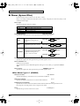
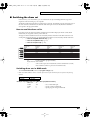
■ Different types of part
The SD-90 has 32 parts, which are divided into groups A and B. Each group is numbered from 01–16; i.e.,
A01–A16 and B01–B16.
Each part can be set either as an Inst part or a Drum part. Inst parts are used to play melody, bass, etc.
Drum parts are used to play percussion-type sounds. This setting is called the Part Mode.
By default, the following part mode is selected for each part.
Part mode
Inst part
Drum part
Corresponding parts
A01–09, A11–16, B01–09, B11–16
A10, B10
■ Polyphony and voices
Each of the SD-90’s sounds consist of units called “voices.” There is a limit to the number of voices that
can be used, and the SD-90 is able to use 128 voices simultaneously. Some sounds (instruments) use more
than one voice ("Instrument list (GM2 / Native mode)" (p. 129)). The main reason that an instrument
uses some voices is so that velocity can be used to shift between different sounds, or so that multiple
sounds can be layered to create a richer tone.
When you attempt to play more than 128 voices on the SD-90, the most-recently played note will be given
priority, and the oldest of the currently-sounding notes will be turned off one by one. If you are using
only instruments that consist of only one voice, you will be able to play 128 notes simultaneously.
However, if you use instruments that consist of two or four voices, fewer than 128 notes can be played
simultaneously. Even if a MIDI note-off message is received, a voice will continue to be used as long as
that note continues to sound. You need to remain aware of this, particularly when using sounds that have
a long release time.
19
sd90_manual_e.book 20 ページ 2004年10月4日 月曜日 午後3時28分
Using the internal sound generator
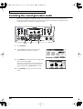
Switching the sound generator mode
Here’s how to switch the sound generator mode. The sound generator mode can be switched from the
front panel, or by MIDI messages from an external device. Please be aware that the sound generator will
be initialized when you switch the sound generator mode.
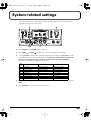
fig.5-02
4
1, 5
1.
2
3
Press [SYSTEM].
fig.7-01a_67.2
2.
Turn the [V1] knob to select the desired sound
generator mode (GM2, Native, GS, XGlite).
fig.5-02a
3.
Press [ENTER]. You will switch to the sound generator
mode you selected in step 2.
The current sound generator mode is indicated in the
right side of the display. If none of the modes has a
symbol displayed by it, Native mode is selected.
4.
20
Press [SYSTEM] once again to return to the main
screen.
sd90_manual_e.book 21 ページ 2004年10月4日 月曜日 午後3時28分
Using the internal sound generator
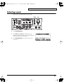
Selecting a part
Here’s how to select the part that you want to edit.
fig.5-03
1, 3
1.
2
Press [INST/DRUM SET].
fig.5-03a_67.2
2.
Press [PART ] or [PART ] to select the part to be
edited. The number of the part currently being edited is
indicated at the bottom of the display.
3.
Press [INST/DRUM SET] once again to return to the
main screen.
21
sd90_manual_e.book 22 ページ 2004年10月4日 月曜日 午後3時28分
Using the internal sound generator
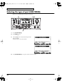
Selecting the type of part (INST/DRUM)
Here’s how to select the type (Part Mode) for each part.
fig.5-04
2
1, 4
3
1.
2.
Press [INST/DRUM SET].
Press [PAGE
] once.
fig.5-04a_67.2
3.
Turn the [V1] knob to select the desired part mode
(INST or DRUM).
The part mode has now been selected.
fig.5-04b_67.2
4.
22
Press [INST/DRUM SET] once again to return to the basic screen.
sd90_manual_e.book 23 ページ 2004年10月4日 月曜日 午後3時28分
Using the internal sound generator
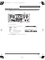
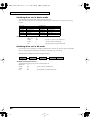
Selecting the sound set
In GM2 mode you can choose one of four different sound sets. In Native mode you can choose one of six
different sound sets.
fig.5-05
1, 3
2
1.
Press [INST/DRUM SET].
fig.5-05a_67.2
2.
Turn the [V3] knob to select the desired sound set.
CLASIC:
Classical
CONTEM:
Contemporary
SOLO:
Solo
ENHANC:
Enhanced
SP 1:
Special 1 (Native mode only)
SP 2:
Special 2 (Native mode only)
The sound set has now been selected.
3.
Press [INST/DRUM SET] once again to return to the main screen.
23
sd90_manual_e.book 24 ページ 2004年10月4日 月曜日 午後3時28分
Using the internal sound generator
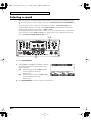
Selecting a sound
If the part type is Inst, use the following procedure to select a sound. First make sure that the part type is
Inst. For details on how to set the part type to Inst, refer to "Selecting the type of part (INST/DRUM)" (p.
22).
On the SD-90, the sound of an Inst part is specified by two numbers: an Instrument number and a
Variation number. There are 128 sounds whose variation number is 000, and these make up the basic
sounds of the SD-90. These are referred to as “capital sounds.”
By changing the MIDI bank number of these sounds, you can select variations that have a different tonal
character. These are called “variation sounds.” For details on the various sounds that can be selected,
refer to "Instrument list (GM2 / Native mode)" (p. 129).
fig.5-06
1, 3
2
1.
Press [INST/DRUM SET].
fig.5-06a_67.2
24
2.
Turn the [V1] knob or [V2] knob to select the sound. The
sound name (instrument) shown in the center of the
display will change.
[V1]: Selects the capital sound. The INST (number)
shown in the display will change
simultaneously.
[V2]: Selects the variation sound. The VAR (number)
shown in the display will change
simultaneously.
3.
Press [INST/DRUM SET] once again to return to the main screen.
sd90_manual_e.book 25 ページ 2004年10月4日 月曜日 午後3時28分
Using the internal sound generator
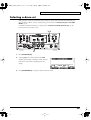
Selecting a drum set
If the part type is Drum Set, use the following procedure to select a drum set. First make sure that the part
type is Drum. For details on how to set the part type to Drum, refer to "Selecting the type of part (INST/
DRUM)" (p. 22).
For details on the drum sets that are available, refer to "Instrument list (GM2 / Native mode)" (p. 129).
*
Drum sets do not have variation sounds.
fig.5-07
1, 3
2
1.
Press [INST/DRUM SET].
fig.5-07a_67.2
2.
Turn the [V1] knob to select a drum set. The INST
(number) in the display will change, and the drum set
name shown in the center of the display will also
change.
3.
Press [INST/DRUM SET] once again to return to the basic screen.
25
sd90_manual_e.book 26 ページ 2004年10月4日 月曜日 午後3時28分
Using the internal sound generator
Muting/soloing a part
You can “mute” a specified part so that it will not sound. This is convenient when you want to play along
to a backing provided by the SD-90 (“minus-one” playing).
Conversely, you can “solo” a specified part so that the remaining parts will be muted.
Here’s how to mute/solo a part.
*
Solo takes priority between solo and mute settings. This means that if you specify Solo for a part that was previously
muted, Mute will be defeated for that part, and it will be set to Solo. Even if you subsequently cancel Solo, that part
will not return to Mute. If you want to mute that part once again, use the procedure described in “Muting a part.”
■ Muting a part
fig.5-08
1, 4
2
3
1.
2.
Press [INST/DRUM SET].
Press [PART ] or [PART ] to select the part that you want to mute.
fig.5-08a_67.2
3.
When you hold down [SHIFT] and press [PART ], the
part you selected in step 2 will be muted. When you
press [SHIFT]+[PART ] once again, muting will be
defeated.
The bar graph of a muted part will be displayed as
shown in the diagram at right.
4.
26
Press [INST/DRUM SET] once again to return to the main screen.
sd90_manual_e.book 27 ページ 2004年10月4日 月曜日 午後3時28分
Using the internal sound generator
■ Soloing a part
When multiple parts are sounding, you can cause only the currently selected part to sound, allowing you
to check the performance of that part. This is referred to as “soloing” the part.
fig.5-09
1, 4
2
3
1.
2.
Press [INST/DRUM SET].
Press [PART ] or [PART ] to select the part that you want to solo.
fig.5-09a
3.
Hold down [SHIFT] and press [PART ] to solo the part
you selected in step 2. Solo will be defeated when you
press [SHIFT]+[PART ] once again.
Parts other than the soloed part will not sound, nor will
the bar graph be displayed.
4.
Press [INST/DRUM SET] once again to return to the main screen.
27
sd90_manual_e.book 28 ページ 2004年10月4日 月曜日 午後3時28分
Using the internal sound generator
About parameters
This section explains the parameters (items that you can set). Parameters are settings that determine how
a sound is produced, and the process of modifying the values of the parameters is called “editing.”
If you are using the SD-90 in GM2 mode or Native mode, some of the Part parameter values can be
edited from the panel of the SD-90 itself. In other modes, parameter values cannot be edited from the
panel of the SD-90. However, the parameters can be edited by using the editing functionality of your
computer software or sequencer.
For details on how to edit the parameters, refer to the “MIDI implementation” (MIDIImple_E.pdf) on the
included CD-ROM. The adjustable range of each parameter is printed in this manual as described in the
comment column of the MIDI implementation.
Internal operation of parameters
When you select a sound, the sound data is loaded into a memory location called the “temporary area.”
The SD-90 produces sound based on the data in this temporary area.
fig.5-14
When you edit a sound or drum set, you are temporarily
modifying the settings of the data in the temporary area. It is
not possible for the edited sounds to be saved in the
internal memory of the SD-90. Your edits will be lost when
you turn off the power. If you want to preserve the edited
state, you can either make a note of the settings, or save
them on an external MIDI device, such as a MIDI sequencer
("Writing/loading SD-90 settings" (p. 93)).
28
Internal sounds
Called up
Temporary area
sd90_manual_e.book 29 ページ 2004年10月4日 月曜日 午後3時28分
Using the internal sound generator
Editing the parameters
Parameters can be edited from the panel of the SD-90 only in GM2 mode and Native mode.
*
It is not possible to preserve the edited state of the audio mixer in the SD-90’s internal memory. Your edits will be
lost when the power is turned off. If you want to preserve the edited state, you can either make a note of the settings,
or save them on an external MIDI device such as a MIDI sequencer ("Writing/loading SD-90 settings" (p. 93)).
■ Editing part parameters
You can change the way in which the sound selected for a part will be heard, to adjust the sound ideally
for your performance. Part parameters include parameters that adjust the volume, tonal character, and
pitch.
fig.5-10
4
2
5
6
1.
Make sure that the sound generator mode is set to either GM2 or Native. If GM2 or Native is not selected,
refer to "Switching the sound generator mode" (p. 20).
2.
Press [INST/DRUM SET].
3.
Select the part and sound as described in the procedures for "Selecting a part" (p. 21) and "Selecting a
sound" (p. 24).
fig.5-10a_67.2
4.
After you have selected the part and sound, press
[PAGE ] or [PAGE
want to edit.
] to access the parameter that you
5.
Turn the [V1]–[V3] knobs.
The value of the parameter you selected in step 4 will
change.
6.
If you want to keep the results of your editing, hold down [SHIFT] and press [ENTER] after step 5. The
current setting will be transmitted from MIDI OUT.
*
If you want to transmit the state of the sound generator to an external MIDI device all at once, use Bulk Dump. For
details on Bulk Dump, refer to "Transmitting a bulk dump" (p. 93).
29
sd90_manual_e.book 30 ページ 2004年10月4日 月曜日 午後3時28分
Using the internal sound generator
■ Editing in the list display
Part parameters can also be edited in a list display. This is convenient when you want to edit a larger
number of parameters at once.
fig.5-11
2, 4
1
3
1.
Press [INST/DRUM SET].
fig.5-11a_67.2
30
2.
Simultaneously press [PAGE ] and [PAGE
parameters will be displayed in a list.
3.
In this state, you can turn the [V1] knob to select the
parameters that you want to edit. When you turn the
[V3] knob, the value of the selected parameter
(highlighted) will change.
4.
Once again press [PAGE ] and [PAGE
]. The
] simultaneously to return to the icon display.
sd90_manual_e.book 31 ページ 2004年10月4日 月曜日 午後3時28分
Using the internal sound generator
■ Editing parameters that are common to all parts
Here’s an example of how to edit parameters that are common to all parts.
fig.5-12
1
2
1.
3
4
Simultaneously press [PART ] and [PART ]. A screen will appear in which you can edit parameters for
all parts.
fig.5-12a_67.2
2.
Turn the [V1] knob to select the parameter that you
want to edit (e.g., Master Volume).
3.
Turn the [V3] knob to adjust the value of the parameter
you selected in step 2.
4.
If you want to keep the results of your edit, hold down [SHIFT] and press [ENTER] after step 3. The
current setting will be transmitted from the USB connector ("USB mode" (p. 71)) or the MIDI OUT
connector ("MIDI mode" (p. 71)).
31
sd90_manual_e.book 32 ページ 2004年10月4日 月曜日 午後3時28分
Using the internal sound generator
About parameters that can be edited from the SD-90’s panel
The following parameters can be edited from the panel in GM2 mode or Native mode.
Parameter name
INST/DRUM SET
Channel Volume
Portamento SW
Filter Resonance
Release Time
Decay Time
Vibrato Depth
Reverb Send Level
Pitch Bend Sensitivity
Coarse Tune
Scale/Octave Tuning Adjust
Legato SW
Part Keyboard Fade Width Lower
Part Keyboard Range Upper
Part Dry Send Level
Part Output Assign
Master Fine Tuning
Parameter name
Modulation Depth
Pan
Portamento Time
Brightness
Attack Time
Vibrato Rate
Vibrato Delay
Chorus Send Level
Fine Tune
Mono/Poly Mode
RX Channel
Part Velocity Sens Offset
Part Keyboard Range Lower
Part Keyboard Fade Width Upper
Part Output MFXSelect
Master Volume
Master Coarse Tuning
On the SD-90, parameter values are specified for the Part. In other words, these parameters belong to the
part, and not to the sound (instrument). For example, if you set Vibrato Rate to +20 and then select a
different sound for that part, the Vibrato Rate of the newly selected sound will stay at +20, and will not be
the default setting of +/-0. Parts that belong to the Part in this way are called “part parameters.”
■ Part parameters (GM2 mode, Native mode)
INST/DRUM SET
INST, DRUM
The part mode can be switched between Inst and Drum Set.
Select INST for parts that will play conventional instrumental sounds (Inst parts). Select DRUM for parts
that will play percussion or drum sounds (Drum parts). For a drum part, each different MIDI note
number will play a different sound (instrument), allowing you to play a variety of percussion instrument
sounds from a single part ("Drum set list (GM2 / Native mode)" (p. 139)).
Each part 1–16 can be set either as an Inst part (to play a conventional sound), or a Drum part (to play a
drum set).
Modulation Depth [cc#1]
Specifies the depth of vibrato.
0–127
Volume [cc#7]
0–100–127
Adjusts the volume of each part. Increasing this value will make the sound louder. The overall volume of
the entire SD-90 is adjusted by the [VOLUME] knob. If the [VOLUME] knob is set to the minimum
position, there will be no sound even if you raise this level parameter.
Pan [cc#10]
L64–0–63R
Adjusts the pan (localization of the sound image; effective when stereo output is used) of the part.
32
*
For some sounds, a small amount of sound may be heard from the opposite speaker even if this parameter is set to far
right or far left.
*
In a drum set, the pan setting of each individual percussion sound is fixed. When you edit the pan setting of a drum
part, the overall panning of the entire drum set will change.
sd90_manual_e.book 33 ページ 2004年10月4日 月曜日 午後3時28分
Using the internal sound generator
Portamento SW [cc#65]
ON/OFF, (PATCH : Native mode only)
Turn this ON when you want to use portamento.
Portamento Time [cc#5]
0–127, (PATCH : Native mode only)
Adjusts the time over which the next pitch will be reached.
Portamento is a function that changes the pitch smoothly from one note to the next.
Portamento will be switched on/off when a Portamento message is received. Portamento Time specifies
the speed of the pitch change. A Portamento Control message can be received to specify the “source note
number” (the previously played note).
*
When you apply portamento by playing a note that is below the currently played note, the range of the effect may be
limited (approximately two octaves).
Filter
You can adjust the tonal character of the sound by editing the filter values. The filters of the SD-90 are a
type called Low Pass Filters, which pass the region of sound that lies below a specified frequency. This
frequency is called the Cutoff Frequency. By adjusting the cutoff frequency, you can make the sound
brighter or darker.
The cutoff frequency will also change over time according to an envelope. By adjusting the filter and
envelope, you can create sounds that have movement and expression.
fig.p8-1j
Higher frequencies
Low
pass
filter
Cutoff frequency
Lower frequencies
TVF Resonance [cc#71]
-64–0–+63
Increasing the resonance value will emphasize the harmonics in the region of the cutoff frequency, giving
a distinctive character to the sound.
*
For some sounds, negative (-) settings of Resonance will not produce any audible difference.
fig.p8-2j
Level
Frequency
Cutoff frequency
Low
High
Resonance
TVF Cutoff Freq (TVF Cutoff Frequency) [cc#74]
-64–0–+63
Sets the cutoff frequency of the filter.
Positive (+) settings for the Brightness parameter will raise the cutoff frequency. Negative (-) settings will
lower the cutoff frequency. Increasing this value in the positive direction will pass more of the highfrequency component, making the sound brighter (harder). Increasing this value in the negative direction
will cut more of the high-frequency component, making the sound more mellow (darker).
*
For some sounds, positive (+) settings of TVF Cutoff Freq will not produce any audible difference.
33
sd90_manual_e.book 34 ページ 2004年10月4日 月曜日 午後3時28分
Using the internal sound generator
Envelope
fig.p8-3j
The sound of a musical instrument changes over time from the
moment the note begins until it ends. Such change can be expressed
by the graph shown below. The shape of this change is distinctive of
that particular instrument, and is an important factor that allows us
to recognize the type of instrument. This shape is called the
“envelope.”
Low pass filter characteristics
Level
Frequency
Cutoff frequency
fig.p9-1j
Filter
The envelope of a musical instrument sound will
A: Attack time
D: Decay time
change depending on how the instrument is played. For
Cutoff frequency
R: Release time
example, when a trumpet is blown strongly, the sound
will have a sharp and rapid attack, but when blown
Envelope
Sound ends
gently, the attack will be softer.
To adjust the sharpness of the attack, you can edit the
Attack Time of the envelope. By adjusting the envelope
Time
Level
A
D
R
parameters in this way, you can express a wide variety
Note On
Note Off
of the characteristics of an instrument.
The shape of the envelope that you specify in this way
will also affect the movement of the cutoff frequency.
If the cutoff frequency is lowered, it will rise as the envelope rises and fall as the envelope falls.
TVF&TVA Release [cc#72]
-64–0–+63
This adjusts the time from when you release the key (note-off message) until the sound decays to silence.
The cutoff frequency will also fall accordingly.
TVF&TVA Attack [cc#73]
-64–0–+63
This adjusts the sharpness with which the note begins.
TVF&TVA Decay [cc#75]
-64–0–+63
This adjusts the time from when the attack has been completed until the sustain level is reached (figure 1).
*
For some sounds, the sustain level is 0 (figure 2). For example, this is the case for piano or guitar-type sounds.
*
For some sounds, adjusting the various envelope times may not make any audible difference.
fig.p9-2j
figure 1
Volume
Sounds ends
Sustain Level
Time
A
D
R
Note Off
Note On
figure 2
Volume
Sounds ends
A: Attack time
D: Deacy time
R: Release time
Time
A
Note On
34
D
Note Off
sd90_manual_e.book 35 ページ 2004年10月4日 月曜日 午後3時28分
Using the internal sound generator
Vibrato
fig.p7-1j
Vibrato is an effect that cyclically modulates the
pitch. By applying vibrato, you can make your
performance more expressive.
Delay
Depth
Note On
Rate
Vibrato Rate [cc#76]
-64–0–+63
This adjusts the speed (frequency) at which the pitch is modulated. Positive (+) settings will speed up the
modulation, and negative (-) settings will slow down the modulation.
Vibrato Depth [cc#77]
-64–0–+63
This adjusts the depth at which the pitch is modulated. Positive (+) settings will increase the depth of
pitch modulation, and negative (-) settings will decrease the depth.
Vibrato Delay [cc#78]
-64–0–+63
This adjusts the time to pass before vibrato begins. Positive (+) settings will lengthen the time before
vibrato begins, and negative (-) settings will shorten the time.
Reverb Send Level [cc#91]
This sets the depth of reverb for the part.
0–40–127
Chorus Send Level [cc#93]
This sets the depth of chorus for the part.
0–127
PitchBendSens (Pitch Bend Sensitivity)
0– +/-2–+/-24, (PATCH : Native mode only))
This specifies the maximum change in pitch that can be controlled by pitch bend. A setting of 12 allows
one octave of change, and a setting of 24 allows two octaves of change. With a setting of 0, pitch bend will
not affect the pitch at all.
Fine Tune (Channel Fine Tuning)
-50–0–+50
Use this when you want to make fine adjustments to the pitch of an individual part. Positive (+) settings
will raise the pitch, and negative (-) settings will lower the pitch. By setting two or more parts to the same
MIDI channel and instrument, and using Fine Tune to slightly spread apart the pitch of each part, you can
play these parts together to create rich and spacious sounds.
*
To adjust the pitch of all parts together, edit the Master Fine Tune setting (p. 37).
Coarse Tune (Channel Coarse Tuning)
-64–0–+63
The Channel Coarse Tuning parameter transposes (shifts the key of) an individual part.
“Transpose” means to change the pitch in steps of a semitone. For example, when playing song data from
your sequencer software, you can make the song play in another key without changing the settings of
your software. Or if you want to sing along with the song data playback but the pitch is too high or too
low, you can edit this parameter to transpose the pitch to a comfortable range.
Each step up (down) will raise (lower) the pitch by one semitone. This means that a setting of 12 will
transpose the pitch one octave. With a setting of 0, the pitch will not be changed.
*
To transpose all parts together, use Master Coarse Tuning (p. 37).
Mono/Poly (Mono/Poly mode) [cc#126/127] Poly, Mono, (PATCH : Native mode only)
If this is set to Mono mode, the instrument of that part will play only one note at a time. Using Mono
mode is effective for parts that play naturally monophonic instruments such as trumpet or sax. Select Poly
mode for parts that will be playing chords.
*
For a drum part, switching between mono/poly modes will not affect the sound.
35
sd90_manual_e.book 36 ページ 2004年10月4日 月曜日 午後3時28分
Using the internal sound generator
Scale/Octave Tuning Adjust
-64–0–+63
Scale Tuning is a function that lets you make fine adjustments to the pitch of each note in the octave. You
can make one octave of settings, and these settings will adjust the pitch of all octaves in the same way.
Scale Tune allows you to play scales other than the conventional equal tempered scale.
■ Part parameters (Native mode)
In addition to the Part parameters described in the preceding pages, Native mode also allows you to
adjust the following parameters.
Rx CH (Receive channel)
1–16, OFF
This specifies the MIDI channel that is assigned to the part. If this is turned OFF for a part, all MIDI
messages other than system exclusive messages will be ignored by that part, meaning that it will not
sound.
Legato SW [CC#68]
ON/OFF, (PATCH : Native mode only)
Turn this ON when you want to use legato, and OFF if you do not. Legato is a function that is valid when
MONO mode is selected for the part. If Legato is ON, pressing a note while the previous note is still held
down will cause the sound to be maintained while it shifts to the pitch of the newly pressed note. This lets
you simulate performance techniques such as the “hammering-on” and “pulling-off” used by guitarists.
Part Velocity Sens Offset (Part Velocity Sensitivity Offset) -63–0–+63
This adjusts the degree to which playing dynamics will affect the volume and cutoff frequency.
Part Keyboard Fade Width Lower
0–127
This specifies how the volume will change when you play notes that are outside the lower limit of the
part’s key range. With higher settings of this parameter, the volume will decrease gradually. If you want
there to be no sound at all when you play below the specified key range, set this to 0.
Part Keyboard Range Lower
C-1–UPPER
Specifies the lowest note of the keyboard range for the part.
Part Keyboard Range Upper
LOWER–G9
Specifies the highest note of the keyboard range for the part.
Part Keyboard Fade Width Upper
0–127
This specifies how the volume will change when you play notes that are outside the upper limit of the
part’s key range. With higher settings of this parameter, the volume will decrease gradually. If you want
there to be no sound at all when you play above the specified key range, set this to 0.
fig.5-15
*
It is not possible to set the Lower Range above the
Upper Range, nor the Upper Range below the
Lower. If you attempt to do so, the Lower and
Upper values will change together.
Level
0
Note number
Lower
L.Fade value
Upper
127
U.Fade value
PART OUTPUT ASSIGN
MFX, A, PATCH
This specifies where the output signal of the part will be sent.
MFX:
Output to MFX.
A:
Output the unprocessed sound without using MFX.
PATCH:
The settings of the patch (instrument) will be applied. If the patch is set to use MFX, the
sound will be sent to MFX. If not, the DRY sound will be output.
36
sd90_manual_e.book 37 ページ 2004年10月4日 月曜日 午後3時28分
Using the internal sound generator
PART OUTPUT MFX SELECT
MFX-A, MFX-B, MFX-C
If MFX is selected for Part Output Assign, select one of the three MFX units to which the sound will be
sent.
PART DRY SEND LEVEL
0–127
This specifies the level of the output to the output destination you’ve selected for Part Output Assign.
■ Parameters common to all parts (GM2 mode, Native mode)
The following parameters common to all parts can be edited from the panel of the SD-90.
Master Volume
0–127
Adjusts the volume of all parts. Increasing this value will increase the volume.
The basic overall volume of the SD-90 is adjusted with the [VOLUME] knob. If the [VOLUME] knob is set
to the minimum position, there will be no sound even if you use this parameter to raise the volume.
Master Fine Tuning
415.3–440.0–466.2 Hz
When you are playing in an ensemble with other instruments, or want to adjust the SD-90 to the tuning of
another instrument, you can adjust the Master Tuning in a range from 415.3 Hz to 466.2 Hz. The
displayed value (for example 440.0 Hz) is the frequency of the A4 note (note number 69).
Master Coarse Tuning
-24–0–+24
This parameter transposes the pitch of all parts in semitone steps. For example, when using your
sequencer software to play song data, this parameter can be adjusted to change the key without having to
change the settings of your software. As another example, you can adjust this parameter to transpose the
pitch to a comfortable range when you want to sing along with song data that is too high or too low for
your voice.
Increasing (decreasing) this value by one will raise (lower) the pitch by one semitone. Thus, a setting of 12
will change the pitch by one octave. With a setting of 0, the pitch will not be transposed. This parameter
lets you adjust the pitch in semitone steps over a range of +/-2 octaves.
*
The pitch of drum parts will not change even if you adjust the Master Coarse Tuning to transpose all parts.
37
sd90_manual_e.book 38 ページ 2004年10月4日 月曜日 午後3時28分
Using the effects of the internal sound generator
About the sound generator effects
The SD-90 contains the following four effects processors, and each can be set independently.
Chorus
Chorus is an effect that adds depth and spaciousness to the sound.
Reverb
Reverb is an effect that adds the reverberation typically heard in a concert hall.
Equalizer
This is an effect that boosts or cuts the level of specific frequency bands of the sound, modifying its tonal
character.
Multi-effect
Multi-effect provides 90 different effect types. These include single effects such as distortion and delay, as
well as multiple types that combine two or more effects. Chorus and reverb are additionally provided as
multi-effect effect types, but you can also use the separate chorus and reverb units to apply these effects.
On the SD-90, you can use three of these multi-effects independently.
38
sd90_manual_e.book 39 ページ 2004年10月4日 月曜日 午後3時28分
Using the effects of the internal sound generator
Editing the sound generator effects
You can edit the sound generator effects when the sound generator mode is either GM2 mode or Native
mode.
fig.6-01b
2
4
3
5
1.
Switch the sound generator to GM2 mode (or Native mode). For details on switching the sound generator
mode, refer to "Switching the sound generator mode" (p. 20).
2.
Press [EFFECT]. The sound generator Effect Edit screen will appear.
3.
Press [PART
] or [PART
] to access either the Reverb, Chorus, or MFX page.
Example screen
*
Example screen
MFX cannot be selected if the sound generator mode is GM2 mode.
4.
Turn the [V1] knob to select the parameter that you want to edit (it will be highlighted).
5.
Turn the [V3] knob to modify the value of the parameter you selected in step 4. This completes the steps
needed to edit an effect parameter.
39
sd90_manual_e.book 40 ページ 2004年10月4日 月曜日 午後3時28分
Using the effects of the internal sound generator
Parameters that can be edited in GM2 mode
The sound generator effect parameters that can be edited using the SD-90’s controls will differ depending
on the sound generator mode (GM2 or Native). In the SD-90’s GM2 mode, you can edit the reverb and
chorus parameters. The following parameters can be edited.
■ Reverb (System Effect)
This includes parameters that specify the type of reverb, how the reverb sound will be heard, and how it
will be output.
Reverb Type
Selection for the type of reverb.
Type
Small Room
Medium Room
Large Room
Medium Hall
Large Hall
Plate
Explanation
This reverb simulates the reverberation of a room. It produces a crisp and spacious reverberation.
This reverb simulates the reverberation of a hall. It produces a deeper sensation than
Room.
This simulates a plate echo (a reverb unit that uses the vibration of a metal plate).
Reverb Time 0–127
Specifies the duration of the reverb. Higher settings will produce a longer reverb time. The default setting
will depend on the Reverb Type setting.
Type
Small Room
Medium Room
Large Room
Medium Hall
Large Hall
Plate
Default setting
44
50
56
64
64
50
Reverberation
time (seconds)
1.1
1.3
1.5
1.8
1.8
1.3
■ Chorus (System Effect)
Chorus Type
Selection for the type of chorus. The default setting of each parameter will depend on the Chorus Type.
40
Type
Chorus 1
Chorus 2
Chorus 3
Chorus 4
FB Chorus
Flanger
Explanation
Type
Chorus 1
Chorus 2
Chorus 3
Chorus 4
FB Chorus
Flanger
Feedback
0 (0%)
5 (4%)
8 (6%)
16 (12%)
64 (49%)
112 (86%)
A conventional chorus effect that adds spaciousness and depth to the sound.
A chorus with a flanger-like character, producing a fresh sound.
Produces a sound reminiscent of a jet airplane taking off and landing.
Mod Rate
3 (0.4 Hz)
9 (1.1 Hz)
3 (0.4 Hz)
9 (1.1 Hz)
2 (0.2 Hz)
1 (0.1 Hz)
Mod Depth
5 (1.9 ms)
19 (6.3 ms)
19 (6.3 ms)
16 (5.3 ms)
24(7.8 ms)
5 (1.9 ms)
Rev Send
0 (0%)
0 (0%)
0 (0%)
0 (0%)
0 (0%)
0(0%)
sd90_manual_e.book 41 ページ 2004年10月4日 月曜日 午後3時28分
Using the effects of the internal sound generator
Mod Rate (Modulation Rate)
0–127
Specifies the speed (frequency) at which the chorus sound will be modulated. Higher settings produce
faster modulation.
Mod Depth (Modulation Depth)
0–127
Specifies the depth of modulation for the chorus sound. Higher settings will produce deeper modulation.
Feedback
0–127
Specifies the level of the chorus sound that will be re-input to the chorus (i.e., the amount of feedback).
Feedback lets you produce a denser chorus sound. Increasing this value will raise the feedback level.
Send to Reverb
0–127
Specifies the amount of chorus sound that will be sent to reverb. Higher settings will increase the amount
that is sent to reverb.
■ EQ (Equalizer)
You can make equalizer settings for the output of the sound generator section.
EQL:
Left channel (Lch)
EQR:
Right channel (Rch)
EQ Switch
Switches the equalizer on/off.
Off, On
EQ1 Low Frequency
200/400 Hz
EQ2 Low Frequency
Specify the frequency at which the low range will be adjusted.
200/400 Hz
EQ1 Low Gain
-15–+15
EQ2 Low Gain
-15–+15
Specify the gain (amount of boost or cut) of the low range. Increasing this setting in the positive direction
will emphasize the low range.
EQ1 High Frequency
2000/4000/8000 Hz
EQ2 High Frequency
2000/4000/8000 Hz
Specify the frequency at which the high range will be adjusted.
EQ1 High Gain
-15–+15 dB
EQ2 High Gain
-15–+15 dB
Specify the gain (amount of boost or cut) of the high range. Increasing this setting in the positive direction
will emphasize the high range.
41
sd90_manual_e.book 42 ページ 2004年10月4日 月曜日 午後3時28分
Using the effects of the internal sound generator
Parameters that can be edited in Native mode
The sound generator effect parameters that can be edited using the front panel of the SD-90 will differ
depending on the sound generator mode (GM2 or Native mode). In the SD-90’s Native mode, you can
edit the parameters of the two system effects and three MFX (multi-effects). The following parameters can
be edited.
■ Reverb (System Effect)
This includes parameters that specify the type of reverb, how the reverb will be sounded, and how it will
be output.
Reverb Type
Selection for the type of reverb. The parameters that can be edited will depend on the Reverb Type.
Type
0 (OFF)
1 (Reverb)
2 (SRV Room)
3 (SRV Hall)
4 (SRV Plate)
5 (GM2)
Explanation
Reverb will not be used.
Basic reverb.
Reverb that simulates the reverberation of a room in greater detail.
Reverb that simulates the reverberation of a hall in greater detail.
Reverb that simulates a plate echo (a reverb device that uses a metal plate).
This is the same as GM2 reverb.
Reverb Level
0–127
Specifies the output level of the signal that has passed through the reverb.
Reverb Source
COMMON, PART 1–32
Specifies the output level of the signal that has passed through the reverb.
When Reverb Type is set to 1 (Reverb)
The following parameters can be edited when Reverb Type is set to 1 (Reverb).
Type (Reverb/Delay Type)
Specifies the type of reverb (or delay).
Value
ROOM 1
ROOM 2
STAGE 1
STAGE 2
HALL 1
HALL 2
DELAY
PAN-DELAY
Explanation
Reverb with short duration and high density
Reverb with short duration and low density
Reverb with a greater amount of subsequent reverberation
Reverb with strong early reflections
Reverb with a transparent character
Rich reverb
Conventional delay
Delay with reflections that pan (move) between left and right
Time (Reverb/Delay Time)
0–127
When the Type is ROOM 1–HALL 2 this adjusts the duration of the reverb. When the Type is DELAY or
PAN-DELAY, this specifies the delay time. Increasing this value will produce a more spacious feeling.
HF Damp (Reverb/Delay HF Damp)
Specifies the frequency above which the high-frequency component of the reverb sound will be cut.
Lowering this value will cause a greater portion of the high-frequency range to be cut, producing a softertoned reverb sound. If no cutting is desired, set this to BYPASS.
Values:
42
200, 250, 315, 400, 500, 630, 800, 1000, 1250, 1600, 2000, 2500, 3150, 4000, 5000, 6300, 8000
Hz, BYPASS
sd90_manual_e.book 43 ページ 2004年10月4日 月曜日 午後3時28分
Using the effects of the internal sound generator
Feedback (Delay Feedback)
0–127
When the Type is DELAY or PAN-DELAY, this specifies the amount of delay sound that will be returned
(fed back) to the input of the delay. Raising this value will cause the delay to continue repeating for a
greater number of times.
When Reverb Type is 2 (Room), 3 (SRV Hall), or 4 (SRV Plate)
Pre Delay (Pre Delay Time)
0.0–100 ms
Specifies the amount of time that is to pass after the original sound is heard before the reverb begins to
sound.
Time (Reverb Time)
Specifies the length of time over which the reverb sound will decay.
0–127
Size
1–8
Adjusts the size of the room/hall. Higher settings will simulate a larger space.
High Cut (High Cut Frequency)
Specifies the frequency above which the high-frequency component of the final output sound will be cut.
If no cutting is desired, set this to BYPASS.
Range:
160, 200, 250, 320, 400, 500, 640, 800, 1000, 1250, 1600, 2000, 2500, 3200, 4000, 5000, 6400,
8000, 10000, 12500 Hz, BYPASS
Density (Reverb Density)
0–127
Adjusts the density of the reverb sound. Higher settings will produce a denser sound.
Diffusion (Reverb Diffusion)
0–127
Adjusts the way in which the density of the reverb sound will change over time. With higher settings of
this parameter, the sound will become denser as time passes. The effect of this parameter is easy to notice
with longer Reverb Time settings.
LF Damp Freq (LF Damp Frequency)
Specifies the frequency below which the low-frequency component of the reverb sound will be cut.
Range:
50, 64, 80, 100, 125, 160, 200, 250, 320, 400, 500, 640, 800, 1000, 1250, 1600, 2000, 2500, 3200,
4000 Hz
LF Damp Gain:
-36–0 dB
Adjusts the amount of attenuation for LF Damp. With a setting of “0,” LF Damp will have no effect.
HF Damp Freq (HF Damp Frequency)
Specifies the frequency above which the high-frequency component of the reverb sound will be cut.
Range:
4000, 5000, 6400, 8000, 10000, 12500 Hz
HF Damp Gain
-36–0 dB
Adjusts the amount of attenuation for HF Damp. With a setting of “0,” HF Damp will have no effect.
43
sd90_manual_e.book 44 ページ 2004年10月4日 月曜日 午後3時28分
Using the effects of the internal sound generator
■ Chorus (System Effect)
On the SD-90, the chorus section can also be used as a delay.
Here you can edit parameters that select either chorus or delay, and specify how the chorus/delay sound
will be heard and output.
Chorus Type
Selection for the type of chorus (or delay).
Value
0 (Off)
1 (Chorus)
2 (Delay)
3 (GM2)
Explanation
Chorus/delay will not be used.
Chorus will be used.
Delay will be used.
This is the same as GM2 reverb.
Chorus Output Select
MAIN, REV, MAIN+REV
Specifies the output destination of the signal that has passed through chorus.
figMAIN:
MAIN:
Output the signal to the OUTPUT
of the MIDI sound generator
block.
.6-1(MAIN)
Chorus Input
Chorus
Output
fig.6-2(REV)
REV:
Output the signal only to reverb.
Chorus Input
Chorus
Reverb
Output
fig.6-3(MAIN+REV)
MAIN+REV:
Output the signal to the OUTPUT
of the MIDI sound generator
block, as well as to reverb.
Chorus Input
Chorus
Output
Reverb Input
Reverb
Output
Chorus Level
0–127
Specifies the output level of the signal that has passed through the chorus.
Chorus Parameter 1-12
Edit the chorus parameters.
The parameters that can be edited will depend on the type of chorus/delay you specified for Chorus
Type.
Chorus Source
COMMON, PART 1–32
Specifies the output level of the signal that has passed through the chorus.
When Chorus Type is 1 (CHORUS)
Rate (Chorus Rate)
0.05–10.00 Hz
Specifies the frequency at which the chorus sound will be modulated.
Depth (Chorus Depth)
Specifies the depth to which the chorus sound will be modulated.
0–127
Feedback (Chorus Feedback)
0–127
Specifies the amount of chorused sound that will be returned (fed back) to the input of the chorus.
Increasing this value will produce a more complex chorus effect.
Phase
Specifies the spaciousness of the chorus sound.
44
0–180 degrees
sd90_manual_e.book 45 ページ 2004年10月4日 月曜日 午後3時28分
Using the effects of the internal sound generator
Pre Delay (Chorus Pre Delay)
0.0–100 ms
Specifies the amount of time that is to pass after the original sound has been heard before the chorus
sound is heard. Increasing this value heightens the dispersal effect.
Type (Filter Type)
Specifies the type of filter.
Value
OFF
LPF
HPF
Explanation
The filter will not be used.
The frequency band above the cutoff frequency setting will be cut.
The frequency band below the cutoff frequency setting will be cut.
Cutoff freq (Cutoff Frequency)
Specifies the frequency at which the filter will begin cutting the specified frequency band.
Range:
200, 250, 315, 400, 500, 630, 800, 1000, 1250, 1600, 2000, 2500, 3150, 4000, 5000, 6300, 8000 Hz
When the Chorus Type is 2 (DELAY)
Center (Delay Center)
200–1000 ms, note value
Specifies the delay time for the delay sound panned to the center.
Left (Delay Left)
200–1000 ms, note value
Specifies the delay time for the delay sound panned to the left.
Right (Delay Right)
200–1000 ms, note value
Specifies the delay time for the delay sound panned to the right.
HF Damp
Specifies the frequency at which the high-frequency portion will be cut for the delay sound that is
returned to the input. If you do not want to cut this sound, select BYPASS.
Range:
200, 250, 315, 400, 500, 630, 800, 1000, 1250, 1600, 2000, 2500, 3150, 4000, 5000, 6300, 8000 Hz,
BYPASS
Feedback
-98–+98%
Specifies the amount of feedback. Changing the amount of feedback will change the number of times that
the delay will repeat. Negative (-) settings will invert the phase of the feedback sound.
Center (Delay Center Level)
Specifies the level of the delay sound localized at the center.
0–127
Left (Delay Left Level)
Specifies the level of the delay sound localized at the left.
0–127
Right (Delay Right Level)
Specifies the level of the delay sound localized at the right.
0–127
■ MFX (Multi-effects)
This section explains how to select a multi-effect, and to edit the parameters that determine how the
multi-effect sound is produced and output.
MFX A-C Type (Multi-effect A–C Type)
0–90
Provides for selection among the 90 types of multi-effect. For details on the various effects that are
available, refer to MFX_E.pdf on the included CD-ROM.
MFX A-C Dry Send Level (Multi-effect A–C Dry Send Level)
0–127
Specifies the level at which the signal processed by the multi-effect will be output.
MFX A-C Chorus Send Level (Multi-effect A–C Chorus Send Level)
0–127
Specifies the level at which the signal processed by the multi-effect will be sent to the Chorus effect.
45
sd90_manual_e.book 46 ページ 2004年10月4日 月曜日 午後3時28分
Using the effects of the internal sound generator
MFX A-C Reverb Send Level (Multi-effect A–C Reverb Send Level)
0–127
Specifies the level at which the signal processed by the multi-effect will be sent to the Reverb effect.
MFX A-C Control 1-4 Source (MFX A–C Control 1–4 Source)
Specifies the control source that will modify the multi-effect parameter, and the sensitivity of the control.
Value
OFF
CC01–95
PITCH BEND
AFTERTOUCH
SYS-CTRL 1–4
Explanation
A controller will not be used.
Controller number 1–95 (except for 32)
Pitch bend
Aftertouch
System control 1–4
MFX A-C Control 1-4 Sens (MFX A–C Control 1–4 Sensitivity)
-63–+63
Set this to a positive (+) value if you want to apply changes to the present value in the positive direction
(higher value, toward the right, faster, etc.). Set this to a negative value (-) if you want to apply changes to
the present value in a negative direction (lower value, toward the left, slower, etc.). The greater the value,
the greater the change produced.
MFX A-C Parameter 1-32 (MFX A–C Parameter)
Specifies the parameter of the multi-effect that you want to use. The parameters that can be edited will
depend on the type of multi-effect you select in MFX Type (Multi-effect Type). For details on each effect
parameter, refer to MFX_E.pdf in the included CD-ROM.
Using MFX in Native mode
If you switch the sound generator to Native mode, you will be able to control the sound and MFX
independently. In order to apply MFX to the sound of a specific part, you must do the following two
things.
• Select the location (source) of the parameters used by MFX.
• Send the output of the part to MFX.
Select the location of the parameters used by MFX
MFX A SOURCE (MFX A source)
COMMON, PART 1–32
MFX B SOURCE (MFX B source)
COMMON, PART 1–32
MFX C SOURCE (MFX C source)
COMMON, PART 1–32
MFX parameters (e.g., algorithm, reverb type, distortion type) exist both within the sounds (COMMON)
and outside them. For each of the three MFX units, you can specify which parameters the unit will use.
COMMON:
One of the three sets of parameters stored outside the sounds will be used. A part whose
PART 1–32:
46
Part Output MFX Select setting is set to MFX will use the effect settings you specify, and
will not be affected by the effect settings of the sound that is called up for that part.
The parameters stored within the sound called up for that part will be used. Parts whose
Part Output MFX Select setting is set to MFX will be processed by the MFX effect settings
of the part referenced by MFX. When another sound is called up for the part that is
referenced, MFX A will operate according to the MFX settings of the newly requested
sound, and the previously mentioned parts will also be processed by these effect settings.
sd90_manual_e.book 47 ページ 2004年10月4日 月曜日 午後3時28分
Using the effects of the internal sound generator
Specifying the output destination of the part
PART OUTPUT ASSIGN
MFX, A, PATCH
Specify where the output signal of the part will be sent.
MFX:
Output to MFX.
A:
Output the sound directly, without using MFX.
PATCH:
Use the settings of the sound (patch). If the patch is set to use MFX, it will be sent to MFX.
If the patch is not set to use an effect, it will be output as DRY.
PART OUTPUT MFX SELECT
MFX A, MFX B, MFX C
Selects which of the three MFX units the sound will be sent to when MFX is selected for Part Output
Assign.
PART DRY SEND LEVEL
Specifies the output level of the part when MFX is not used (i.e., when Part Output Assign is set to DRY).
This setting is ignored when MFX is used.
fig.6-4(mfxã÷é~)
MFX output destination
Only one MFX can be selected as the output
destination for one part. It is not possible to output a
part to multiple MFX units simultaneously, or to send
the output of an MFX unit to another MFX.
MFX A
MFX B
MFX A
MFX B
Using sounds from the Enhanced set in Native mode
Immediately after the sound generator mode is switched to Native mode, the three MFX will be assigned
to parts 1, 2, and 3, respectively. When you select sounds from the Enhanced set, the effects will be
applied only to parts 1, 2, and 3 unless you change the settings. If you want to use sounds from the
Enhanced set for other parts in Native mode, perform the following steps.
< Example: Using MFX A for part 4>
1.
Set the MFX A Source to PART4. This allows the MFX A effect to be applied with the settings of the
sound that is called up for part 4.
2.
Set the Part 4 Output Assign to PATCH. This selects PATCH as the output destination for the part. Since
the output setting of an Enhanced sound (patch) is set to MFX, calling up the sound to Part 4 will cause the
signal to be output to MFX.
You can apply an effect even if Part Output Assign is set to MFX. However, in this case, it will be output in a
fixed manner to MFX even if you call up a sound from a different set to Part 4.
*
3.
For Part Output MFX Select, specify which of the three MFX units (A–C) you want to use. For this
example, select MFX A.
■ EQ (Equalizer)
You can make equalizer settings for the output of the sound generator section.
For details, refer to "EQ (Equalizer)" (p. 41).
47
sd90_manual_e.book 48 ページ 2004年10月4日 月曜日 午後3時28分
Using the Audio Mixer
The SD-90 has a rich array of input/output jacks, allowing a wide variety of uses.
This chapter explains the audio mixer which controls the signal flow; i.e., how the input signal from each
jack will be sent to your computer, and how to select the sound that will be monitored.
The general procedure for using the audio mixer is shown below.
Connect the audio device that will be the input source
|
Select the recording source
|
Set the volume of the source
*
A block diagram (a diagram of internal connections) is printed on the top panel of the SD-90. You may wish to
refer to this block diagram for a general understanding of the audio mixer.
Connecting an input source audio device
■ Analog connections
*
You can connect a mic, guitar, CD player, or other device to the analog input jacks on the front panel and
rear panel.
Before making connections to other devices, you must turn down the volume of all devices to prevent malfunction
and/or speaker damage.
Selecting an analog input jack
You can select and use either the front panel MIC/GUITAR jack or the rear panel INPUT jacks. It is not
possible to use both sets of jacks simultaneously. You must first select the analog jack(s) that you want to
use.
fig.3-02a
2
1, 5
48
1.
Press [SYSTEM].
2.
Press [PAGE
] or [PAGE
3
4
] until Select Analog In is displayed.
sd90_manual_e.book 49 ページ 2004年10月4日 月曜日 午後3時28分
Using the Audio Mixer
fig.7-1f)
3.
Turn the [V2] knob to select the analog input jack that
you want to use.
Analog In
Select either Mic/Gtr or Line.
Mic/Gtr:
MIC/GUITAR jack
Line:
Line jacks
4.
*
5.
Press [ENTER]. The settings you made will be stored
in the SD-90.
Do not turn off the power while the settings are being stored (while the display indicates “SAVING...”). Doing so
will result in the loss of all data stored within the SD-90.
Press [SYSTEM] once again to return to the main screen.
Connecting a mic/guitar
fig.3-02
3 1, 2
1.
Turn the GAIN knob fully counterclockwise (minimum position).
2.
If you are connecting a mic, press the GAIN knob so that the GAIN indicator lights. If you are connecting a
guitar, press the GAIN knob so that the GAIN indicator goes dark.
*
3.
*
*
If the GAIN indicator is dark when a mic signal is being input, the audio from the mic will be too weak, since the
MIC/GUITAR jack will be functioning as a guitar input.
Connect your mic or guitar to the front panel MIC/GUITAR jack.
The MIC/GUITAR jack is not compatible with the miniature mics (condenser mics) included with some computers
or sound cards.
Depending on the location of the mic and speakers, you may hear acoustic feedback (a squealing or screeching
sound). If this occurs, take one or more of the following measures:
1. change the direction of the mic,
2. move the mic away from the speakers,
3. turn down the volume.
49
sd90_manual_e.book 50 ページ 2004年10月4日 月曜日 午後3時28分
Using the Audio Mixer
Connecting a CD player
fig.3-03
1
2
1.
Turn the GAIN knob fully counterclockwise.
2.
Connect a CD player or other audio device to the rear panel INPUT jacks.
■ Digital connections
To digitally connect your CD player or digital recorder, connect it to the rear panel OPTICAL IN
connector or COAXIAL IN connector, depending on the type of connector found on your device.
Selecting the digital input jack and sampling frequency
You must select either the OPTICAL IN jack or the COAXIAL IN jack. It is not possible to use both types of
jack simultaneously.
When making digital connections, you must also make sure that the sampling frequency of the connected
recorder, the sampling frequency of the SD-90, and the sampling frequency of the audio handled by the
sequencer program on your computer are all set to the same setting. Use the following procedure to select
the type of digital jack and the sampling frequency you will use.
fig.3-02b
2
1, 5
50
3
4
1.
Press [SYSTEM].
2.
Press [PAGE
3.
Turn the [V2] knob to select the digital jack you will use, and turn the [V3] knob to select the sampling
frequency.
] to make Select Digital In appear in the screen.
sd90_manual_e.book 51 ページ 2004年10月4日 月曜日 午後3時28分
Using the Audio Mixer
fig.7-1eb)
Select Sample Rate44.1kHz, 48kHz
Select 44.1kHz or 48kHz.
* Normally, CD players and MD recorders use a sampling
frequency of 44.1 kHz, and DAT recorders use a sampling
frequency of 48 kHz.
fig.3-02ca)
Select Digital inCox, Opt
Select Cox (Coaxial) or Opt (Optical).
4.
*
5.
Press [ENTER]. The settings you made will be stored in the SD-90.
Do not turn off the power while the settings are being stored (while the display indicates “SAVING...”). Doing so
will result in the loss of all data stored within the SD-90.
Press [SYSTEM] once again to return to the basic screen.
About recording with digital connections
One generation of digital copying (recording) from an audio CD to MD or DAT is permitted. For example,
once you have made a digital copy to an MD, it will not be possible to digitally copy that MD onto
another MD. This is because an audio CD contains (in addition to the audio data) flags that prohibit
digital copying.
In contrast, the signal that is output from the SD-90’s DIGITAL OUT jacks will allow more than one
generation of digital copying.
However, if a CD player or similar device is connected to the SD-90’s DIGITAL IN jack, and the incoming
signal contains flags that prohibit digital copying, digital copying of the signal that is output from the
DIGITAL OUTPUT jack will also be limited to a single generation. For this reason, you should leave the
DIGITAL IN jack unconnected, or turn off the power of the connected digital device unless you need to
use it.
51
sd90_manual_e.book 52 ページ 2004年10月4日 月曜日 午後3時28分
Using the Audio Mixer
Selecting the recording source
The SD-90 contains various setups of mixer settings that specify which input jacks will be sent to the
computer, where the audio effects will be placed, and which output will be monitored. These setups are
called routings, and can be recalled quickly and easily.
*
On the SD-90 you can select the source that will be recorded on your computer simply by switching the
routing. For example, if you want to monitor the sound of your guitar processed by the Guitar Multi effect
while recording only the unprocessed sound, or want to listen to the backing of the internal sound
generator while playing overdubs on your guitar, you can make the various necessary mixer settings
quickly and easily, simply by selecting a routing.
For details on the various types of routing that are available, refer to "About the routing presets" (p.
57)).
If the selected routing is one that uses an audio effect (No. 05--18), the source will be output with the effect applied.
When the power is turned on, the effect type is Space Multi.
■ Selecting a routing
In order to record audio signals on your sequencer software, select a routing that sends the sound from
the SD-90 via the USB cable to your computer.
fig.3-06
1, 3
2
fig.3-07
1.
52
Press one of the SOURCE buttons, as appropriate for
your input source. The button will light, the routing
assigned to that button will be initialized, and the
routing number and connection diagram will appear
in the display.
Display
MIC/GT
LINE IN
DIGITAL IN
WAVE
INST
Input signal
Front panel MIC/GUITAR jack *
Rear panel INPUT jacks
Rear panel digital input jack (OPTICAL IN/COAXIAL IN)
Digital audio played back on your computer
Internal sound generator
Display
REC OUT
Output signal
Digital audio sent from the SD-90 via the USB cable to the computer
MASTER
The SD-90’s OUTPUT 1 jacks, headphone jack
OUT/COAXIAL OUT)
, and digital output jack (OPTICAL
sd90_manual_e.book 53 ページ 2004年10月4日 月曜日 午後3時28分
Using the Audio Mixer
*
MIC/GT will be displayed if Select Analog In is set to Mic/Gtr, and LINE IN will be displayed if Line is selected.
2.
By turning the [V1] knob you can change the routing assigned to the button. For example, if you want to
change the location of the effects, or to change the connections, turn the [V1] knob to select a different
routing.
3.
If you once again press the SOURCE button that you pressed in step 1, the button will go dark, and you’ll
be returned to the main screen.
If you hold down [SHIFT] and press a SOURCE button ([MIC/GUITAR][LINE IN][DIGITAL IN][TRACK
DOWN]), the routing that was first assigned to each button will once again be recalled.
*
Setting the volume of the source sound
You can adjust the volume (recording level) of each source that is sent to your computer or output to the
OUTPUT 1 jacks.
*
The volume of each source can be adjusted in two ways: icon display or list display. Use the method
appropriate for your situation or preferences.
It is not possible to save the edited state of the audio mixer in the SD-90’s internal memory. The
edited state will be lost when you turn off the power. If you want to preserve the edited state, either make a note of the
settings, or save them on an external MIDI sequencer or similar device. ("Writing/loading SD-90 settings" (p.
93))
Input sources and the MASTER output
All input sources are always output to MASTER. The routing will determine which signals are assigned
to be sent via USB to your computer (REC OUT). This means that if you want to record only one source,
you must select a routing in which REC SOURCE is a single item ("Selecting the recording source" (p.
52)). For example, if you want to record only the Digital In, you should select either routing number 02,
12, or 16.
53
sd90_manual_e.book 54 ページ 2004年10月4日 月曜日 午後3時28分
Using the Audio Mixer
■ Editing in the Icon display
fig.3-08
1, 4
2
3
1.
Press one of the SOURCE buttons, according to the input source you want to use. The button will light,
*
indicating that the routing assigned to that button has been selected. The display will show the routing
number and connection diagram.
Routings are numbered from 0–19. For details, refer to "About the routing presets" (p. 57).
2.
Press [PAGE
] or [PAGE
] until the parameter you want to edit is displayed.
fig.3-09
3.
To edit the settings, turn the knob ([V1])–[V3]) for the
parameter you want to edit.
4.
Once again, press the SOURCE button you pressed in
step 1 to return to the main screen.
■ Editing in the List display
fig.3-10
1, 5
2
3
1.
54
4
Press one of the SOURCE buttons, according to the input source you want to use. The button will light,
indicating that the routing assigned to that button has been selected. The display will show the routing
number and connection diagram.
sd90_manual_e.book 55 ページ 2004年10月4日 月曜日 午後3時28分
Using the Audio Mixer
2.
Press [PAGE
3.
Turn the [V1] knob so that the parameter you want to edit is highlighted.
4.
] and [PAGE
] simultaneously. The parameters will be listed in the display.
Turn the [V3] knob to edit the value.
fig.3-11
5.
Once again, press the SOURCE button you pressed in
step 1 to return to the icon display.
■ Audio mixer parameter list
This section describes the Audio Mixer parameters
that can be adjusted in each screen (when using the
Icon display).
Knob
V1
V2
V3
Knob
V1
*
MASTER
(master volume)
Display (Name)
A Vol
(analog volume)
Range
00–18
0–127
0–127
Range
0–100–127
V2
A Muted
(analog mute)
OFF, ON
V3*
A Send (analog
send level)
0–64–127
Explanation
Routing preset
Recording level
sent to computer
Example screen
Output level from
OUTPUT 1 jacks
Explanation
Example screen
Volume of the analog input jacks
Mute on/off for
the analog input
jacks
Send level from
the analog input
jack to effects
Valid only for preset routing 05.
Knob
V1
*
Display (Name)
TYPE
RECOUT
(record volume)
Display (Name)
D Vol
(digital volume)
Range
0–100–127
V2
D Mute
(digital mute)
OFF, ON
V3*
D Send (digital
send level)
0–64–127
Explanation
Example screen
Volume of the
digital input jacks
Mute on/off for
the digital input
jacks
Send level from
the digital input
jack to effects
Valid only for preset routing 05.
Knob
V1
V2
V3*
Display (Name)
W Vol
(wave volume)
W Mute
(wave mute)
W Send (wave
send level)
Range
0–100–127
OFF, ON
0–64–127
Explanation
Volume of USB
audio
Mute on/off for
USB audio
Example screen
Send level from
the USB audio to
effects
Page 5(fig.3-16)
55
sd90_manual_e.book 56 ページ 2004年10月4日 月曜日 午後3時28分
Using the Audio Mixer
*
Knob
Display (Name)
Range
V1
INST Vol (instrument volume)
0–100–127
V2
INST Send (instrument send
level)
OFF, ON
V3
INST Mute (instrument mute)
0–64–127
Explanation
Example screen
Volume of the internal sound generator
Send level from
the internal sound
generator to the
effects*
Mute on/off for
internal sound
generator
Valid only for preset routing 05.
List display
In the list, the parameters are shown in the following order.
fig.3-11
Record Volume
Master Volume
Analog Volume
Analog Mute
Analog Send Level *
Wave Volume
Wave Mute
Wave Send Level *
Digital Volume
Digital Mute
Digital Send Level *
Inst Volume
Inst Mute
Inst Send Level *
Rec Monitor Sw
Mixer Mute
*
56
Only preset routing 05 is valid.
sd90_manual_e.book 57 ページ 2004年10月4日 月曜日 午後3時28分
Using the Audio Mixer
About the routing presets
This section describes the 19 different routing presets.
■ Basic routing
This is the most basic routing. All input sources will be mixed and sent via USB to the computer, and the
same signals will be output from the OUTPUT 1 jacks. Audio effects will not be used.
No.
Type
Display
Connections
MIC/GT
REC OUT
00
Mix all input sources and
record them
DIGITAL IN
Default
WAVE
MASTER
INST
■ Record the dry sound (Default Source Recording)
The selected input source will be sent to the computer without being processed. Audio effects will not be
processed. Use one of these routings when you want the input signal to be recorded into your computer
without being processed.
No.
Type
Display
Connections
MIC/GT
REC OUT
01
Record from the analog
jacks
DIGITAL IN
Default Ana Rec
WAVE
MASTER
INST
MIC/GT
REC OUT
02
Record from the digital
jacks
DIGITAL IN
Default Dig Rec
WAVE
MASTER
INST
MIC/GT
REC OUT
03
Record from the USB conDefault Wav Rec
nector
DIGITAL IN
WAVE
MASTER
INST
MIC/GT
REC OUT
04
Record the output of the
internal sound generator
DIGITAL IN
Default Syn Rec
WAVE
MASTER
INST
57
sd90_manual_e.book 58 ページ 2004年10月4日 月曜日 午後3時28分
Using the Audio Mixer
■ Apply effects and track-down
This routing lets you mix all input sources, apply send/return type effects, and send the result to your
computer. The send level can be adjusted for each input source. Use this routing when you want to apply
reverb or Space Multi to the output of your computer or audio device, or to the internal input.
No.
Type
Display
Connections
MIC/GT
REC OUT
05
Apply effects and trackdown
DIGITAL IN
AFX
Send/Return AFX
WAVE
MASTER
INST
*
If you are using a send/return type effect, the output may be prone to distortion. Refer to the level meter in the
display, and adjust the USB audio level appropriately.
■ Insert effects and track-down
This routing lets you mix all input sources, insert an effect, and send the result to your computer. Use this
routing when you want to apply a mastering effect to the overall output of a sequencer program on your
computer, and record the result.
No.
Type
Display
Connections
MIC/GT
REC OUT
06
Insert effects and trackdown
DIGITAL IN
Mix to AFX
AFX
WAVE
MASTER
INST
■ Apply effects to each channel and record
These routings let you insert an effect only into the input source you want to record, mix all input sources,
and send the result to your computer. The output level of the audio effect will determine the volume of
the source processed by the effect. For example, you can use one of these routings when you want to
apply an effect (guitar multi) to the guitar input, mix it with the backing, and record the combined result.
No.
Type
Display
Connections
MIC/GT
AFX
REC OUT
07
Insert an effect into an analog input and record the Ins Ana, Mix Rec
mix
DIGITAL IN
WAVE
MASTER
INST
MIC/GT
REC OUT
08
Insert an effect into a digiIns Dig, Mix Rec
tal input and record the
mix
DIGITAL IN
AFX
WAVE
MASTER
INST
58
sd90_manual_e.book 59 ページ 2004年10月4日 月曜日 午後3時28分
Using the Audio Mixer
No.
Type
Display
Connections
MIC/GT
REC OUT
09
Insert an effect into the
USB input and record the
mix
DIGITAL IN
Ins Wav, Mix Rec
WAVE
AFX
MASTER
INST
MIC/GT
REC OUT
10
Insert an effect into the internal sound generator
Ins Syn, Mix Rec
output and record the mix
DIGITAL IN
WAVE
MASTER
INST
AFX
■ Apply effects and record a single channel
These routings let you insert an effect into only the input source that you want to record, and record only
that channel on your computer. All inputs can be monitored. The output level of the audio effect will
determine the level of the source processed by the effect. For example, you can use one of these routings
when you want to apply an effect (vocal multi) to a mic input, and record only that source while
monitoring the backing as well.
No.
Type
Display
Connections
MIC/GT
AFX
REC OUT
11
Insert an effect into the anIns Ana, Src Rec
alog input and record it
DIGITAL IN
WAVE
MASTER
INST
MIC/GT
REC OUT
12
Insert an effect into the
Ins Dig, Src Rec
digital input and record it
DIGITAL IN
AFX
WAVE
MASTER
INST
MIC/GT
REC OUT
13
Insert an effect into the
USB input and record it
DIGITAL IN
Ins Wav, Src Rec
WAVE
AFX
MASTER
INST
MIC/GT
14
Insert an effect into the
output of the internal
sound generator and
record it
REC OUT
DIGITAL IN
Ins Syn, Src Rec
WAVE
MASTER
INST
AFX
59
sd90_manual_e.book 60 ページ 2004年10月4日 月曜日 午後3時28分
Using the Audio Mixer
■ Monitor the effect while recording only the dry sound
These routings let you insert an effect only into the input source you want to record, monitor the overall
mix including the effect sound, and record only the dry sound of that (input source) channel into your
computer. The output level of the audio effect will be the level of the source processed by the effect. For
example, you can use one of these routings when you want to apply an effect (guitar multi) to a guitar
source, monitor the overall sound including the backing, and record only the unprocessed source.
No.
Type
Display
Insert an effect into the an- Ins Ana, Dry Rec
alog input and record the
dry sound
Connections
MIC/GT
AFX
REC OUT
DIGITAL IN
15
WAVE
MASTER
INST
Insert an effect into the
digital input and record
the dry sound
Ins Dig, Dry Rec
MIC/GT
REC OUT
DIGITAL IN
16
AFX
WAVE
MASTER
INST
Insert an effect into the
USB input and record the
dry sound
Ins Wav, Dry Rec
MIC/GT
REC OUT
DIGITAL IN
17
WAVE
AFX
MASTER
INST
18
Insert an effect into the
output of the internal
sound generator and
record the dry sound
Ins Syn, Dry Rec
MIC/GT
REC OUT
DIGITAL IN
WAVE
MASTER
INST
60
AFX
sd90_manual_e.book 61 ページ 2004年10月4日 月曜日 午後3時28分
Using the audio effects
On the SD-90 you can use one internal stereo audio effect.
The signal to which the effect will be applied (i.e., the location of the effect) is selected by the routing
preset of the audio mixer. Depending on the location, the effect can be applied not only to the audio
input/output, but also to the output of the internal sound generator. You can also apply an effect to the
input source and send the result to your computer (recording “wet”), or monitor the processed sound
while recording only the unprocessed (dry) sound.
The general procedure for using an audio effect is shown below.
Select the location of the effect
|
Select the effect algorithm
|
Edit the effect
Select the location of the effect (Mixer Routing)
The location of the audio effect is determined by the audio mixer routing you select. For details, refer to
"Selecting a routing" (p. 52).
61
sd90_manual_e.book 62 ページ 2004年10月4日 月曜日 午後3時28分
Using the audio effects
Selecting the type of effect (Algorithm)
According to the routing, select the effect type (algorithm). For details on the effect algorithms that are
available, refer to "About the effect algorithms" (p. 65).
fig.4-01
1, 3
2
1.
Press [SELECT]. A list of effect algorithms will appear.
fig.4-02
2.
*
*
3.
62
Turn the [V1] knob so that the desired effect algorithm
is highlighted. The effect algorithm is active from the
moment it is highlighted (i.e., you will hear the effect
immediately).
If you have selected a mixer routing preset (00–04) that does not use the audio effect, no effect will be
applied"Selecting a routing" (p. 52). However, the internal algorithm itself will change.
For some effects such as distortion and lo-fi, the output level may be high even though the source level is low.
Before you switch effects, turn down the [VOLUME] knob to prevent damage to your speakers, and return the level
to an appropriate setting while you monitor the effect.
Listen to the sound, and if you want to edit the effect, proceed to "Editing the effect" (p. 63). To return to
the basic screen, press [SELECT] once again.
sd90_manual_e.book 63 ページ 2004年10月4日 月曜日 午後3時28分
Using the audio effects
Editing the effect
For each effect algorithm, the parameters are set appropriately for the expected use. You can also edit the
parameters to adjust the effect to your liking. For details on the parameters that can be adjusted for each
algorithm, refer to the supplementary material on the included CD-ROM “(AFX_E.pdf).”
There are two ways to edit the effect: icon display and list display. Use the method that is most suitable
for your situation or preferences.
*
It is not possible to save the edited state of the effect in the SD-90’s internal memory. The edited state
will be lost when you turn off the power. If you want to preserve the edited state, either make a note of the settings, or
save them on an external MIDI sequencer or similar device. ("Writing/loading SD-90 settings" (p. 93))
■ Editing in the icon display
fig.4-03
1, 4 2
3
1.
2.
Press [EDIT]. The parameters of the currently selected algorithm will be displayed.
Press [PAGE
] or [PAGE
] until the parameter you want to edit is displayed.
fig.4-04a
3.
To edit the value, turn the [V1]–[V3] knob for the
parameter that you want to edit.
4.
Press [EDIT] once again to return to the main screen.
63
sd90_manual_e.book 64 ページ 2004年10月4日 月曜日 午後3時28分
Using the audio effects
■ Editing in the list display
fig.4-05
1, 5 2
3
1.
4
Press [EDIT]. The parameters of the currently selected algorithm will be displayed.
fig.4-06
2.
Simultaneously press [PAGE
] and [PAGE
A list of parameters will appear in the display.
3.
Turn the [V1] knob to highlight the parameter that
you want to edit.
4.
Turn the [V3] knob (VALUE) to edit the setting.
5.
Press [EDIT] once again to return to the main screen.
].
■ Bypassing the effect
fig.4-07
1, 2
fig.4-08
64
1.
If you want to compare the sound processed by the
effect with the unprocessed sound, press [BYPASS].
The [BYPASS] button will light and the effect block
will be highlighted, indicating that the effect has been
bypassed.
2.
When you press [BYPASS] once again, [BYPASS]
will go dark and you’ll be returned to the previous
state.
sd90_manual_e.book 65 ページ 2004年10月4日 月曜日 午後3時28分
Using the audio effects
About the effect algorithms
This section explains the effect blocks and internal connections used by each algorithm. For details on
the parameters that can be adjusted for each algorithm, refer to “AFX_E.pdf” in the included CD-ROM.
■ Space Multi
This lets you use “spatial-type” effects such as chorus to add spaciousness and depth, flanger or phaser
to add modulation, delay to create echoes, and reverb to add reverberation. These effects can be applied
to the overall sound for listen, or lightly applied when track editing is finished to create a greater feeling
of space ("Apply effects and track-down" (p. 58)).
fig.4-09
Input L
Output L
Enhancer
3-Band
Equalizer
Noise
Suppressor
Chorus/
Flanger
Reverb
Output R
Input R
■ Guitar Multi
This algorithm is designed specifically for guitar. It provides a compressor to make the sound more
consistent, distortion to distort the sound, and also chorus and flanger, covering a wide range of styles
from clean to distorted sounds. It’s a convenient way to produce anything from mild overdrive to extreme
distortion.
fig.4-10
Input L
Output L
Compression
Sustainer
Overdrive/
Distortion
Amp
Simulator
Equalizer
Noise
Suppressor
Chorus/
Flanger
Delay
Output R
Input R
■ Vocal/Bass Multi
This algorithm is suitable when recording vocals or bass through a mic. It provides a compressor to
make the volume more consistent, a noise suppressor to remove unwanted noise, and delay and
chorus to add spatial resonance. By using the lo-fi processor you can simulate a lo-fi sound, making it
sound as if the source were recorded on vintage audio equipment.
fig.4-11
Input L
Output L
Comp
Limiter
Lo-Fi
Processor
Equalizer
Noise
Suppressor
Delay
Chorus/
Flanger
Output R
Input R
■ Groove Multi
This is a multi-effect designed for dance music. It is convenient when you want to process a song from an
audio CD or similar source to create phrase materials.
fig.4-12
Input L
Output L
Comp/
Limiter
Input R
Lo-Fi
Processor
Filter
Noise
Suppressor
Stereo
Flanger
Output R
65
sd90_manual_e.book 66 ページ 2004年10月4日 月曜日 午後3時28分
Using the audio effects
■ Isolator
*
This cuts the level independently for separate frequency bands, letting you eliminate unwanted sounds.
For example, you can use it to extract a desired instrument (such as drums or vocals) from a phrase taken
from an audio CD.
On a conventional equalizer, there will still be some sound even if the gain of each frequency band is lowered
completely, but on an isolator no sound at all will remain.
fig.4-13
Input L
Output L
Comp/
Limiter
Isolator
Noise
Suppressor
Pitch
Shifter
Output R
Input R
■ Center Canceller
*
When a stereo source such as an audio CD is input, this will eliminate the sounds that are localized at the
center, such as vocals and bass. This is useful when you want to process a song from an audio CD to
create a collection of phrases.
For some sources, you may not be able to obtain the desired result; for example, sounds other than the one you want
to eliminate may also be lost. Also, this may not work correctly on musical sources with deep reverb, or if the sound
you want to eliminate is not localized at the center.
fig.4-14
Input L
Output L
Center
Canceller
3-Band
Equalizer
Noise
Suppressor
Output R
Input R
■ Lo-Fi Processor
*
This creates a “lo-fi sound” by lowering the sample rate or reducing the number of bits.
Raising the input level may cause the output level to suddenly become very loud. Before you adjust the lo-fi
processor, it is best to turn down the volume to prevent speaker damage, and then adjust the level appropriately
while listening to the result.
fig.4-15
Input L
Output L
Lo-Fi
Processor
Noise
Suppressor
Noise
Generator
Output R
Input R
■ Surround RV (Surround Reverb)
This is a reverb effect that uses Roland’s RSS technology to provide multi-speaker surround output (four
speakers). It expands the sound field for normal listening.
fig.4-16
Front Output L
Input L
Noise
Suppressor
Surround
Reverb
Front Output R
Rear Output L
Input R
Rear Output R
*
66
Conventional stereo playback reproduces the sound from two speakers placed in front, at the left and
right. In contrast, a surround function uses speakers placed in back as well as in front to create a sound
field that extends left to right and also front to back. You will need the appropriate number of speakers
(four) for surround playback.
It is not possible to place (pan) or move (fly) an audio source in the surround sound field.
sd90_manual_e.book 67 ページ 2004年10月4日 月曜日 午後3時28分
Using the audio effects
Connecting the speakers
fig.4-16a
At the factory settings, the OUTPUT 2 jacks are set to
output the signals from the internal sound generator.
If you want to use surround reverb as the audio effect,
you must connect external speakers to the OUTPUT 2
jacks, and make settings so that these jacks output the
signal for the rear speakers.For best results, try to
listen from the “sweet spot” shown in the diagram at
right.
It is best to set the VOLUME knob to approximately
the two o’clock position. However, since the VOLUME
knob cannot be used to adjust the output of the rear
speakers, you should turn the VOLUME knob slightly
down if it is difficult to hear the output of the rear
speakers.
60°
60°
60°
60°
Using surround output
fig.4-17
2
1, 4
*
1.
2.
3
When surround reverb is used, it may be easier for the output to become distorted. Watch the level meters shown in
the display, and make adjustments so that the levels of the audio and the internal sound generator are appropriate.
Press [SYSTEM].
Press [PAGE
] or [PAGE
] until Select Output 2 is displayed.
fig.dummy(fig.4-18)
3.
Turn the [V1] knob to select the output for the
OUTPUT 2 jack. For this example, select REAR.
Select Output 2
AUTO: Normally, the sound of the internal sound
generator will be output. If Surround Reverb
is being used as the audio effect algorithm,
then the sound for the rear speakers will be
output.
INST:
The sound of internal sound generator will always be output.
REAR: The audio effect sound will always be output. If an algorithm other than Surround Reverb is
used, nothing will be output.
67
sd90_manual_e.book 68 ページ 2004年10月4日 月曜日 午後3時28分
Using the audio effects
Output2
Other than Surround Reverb
Surround reverb
4.
*
*
Effect not used
Effect used
Effect not used
Effect used
Auto
INST
INST
--INST
Inst
INST
INST
INST
INST
Rear
------Rev
Press [SYSTEM] once again to return to the main screen.
If you set Select Output 2 to INST when using Surround Reverb as the audio effect, the full surround effect will
not be obtained.
If you set Select Output 2 to REAR when you are not using the audio effect, or when you are using an effect other
than Surround Reverb, there will be no sound from the OUTPUT 2 jacks. In this case, you can change Select
Output 2 back to INST.
■ Mastering
This effect divides the source into frequency bands (high and low), and makes the volume more
consistent and improves the balance. By using this effect when you mixdown to MD or DAT, or when
mixing to an audio file (WAV file), you can master the sound at an optimal level.
fig.4-19
L
Input L
Enhancer
Input R
3-Band
Equalizer
R
Noise
Suppressor L
R
68
Output L
High-Band
Comp/Lim
Low-Band
Comp/Lim
Output R
sd90_manual_e.book 69 ページ 2004年10月4日 月曜日 午後3時28分
System-related settings
This chapter explains how to make settings that affect the entire system of the SD-90. The following
parameters can be set in the system screen.
fig.7-1
2
1, 5
4
3
1.
Press [SYSTEM]. The [SYSTEM] indicator will light.
2.
Press [PAGE
3.
Turn the [V1] knob to edit the value of the item in the first line of the display, the [V2] knob to edit the
value of the item in the second line of the display, or the [V3] knob to edit the value of the item in the
third line of the display. The value of the most-recently selected item will be highlighted.
Here’s the basic procedure for setting these parameters.
Display
1
2
3
4
5
6
7
8
9
] or [PAGE
V1
INST Init
MIDI Startup
Control Output
Preview Mode
USB Driver
Analog In
LCD Contrast
System Tempo
Factory Reset
] until the item you want to edit appears in the display.
V2
Bulk Dump INST
INST Startup
MIDI IN1 THRU
Preview Note
--Digital In
-------
V3
Bulk Dump Audio
SysEx.DevID
MIDI IN2 THRU
Preview Velo
Sample Rate
Output2
LCD Mode
-----
4.
When you have selected the desired value, press [ENTER]. If you decide not to change the value, press
[EXIT].
5.
Press [SYSTEM] once again to return to the main screen.
69
sd90_manual_e.book 70 ページ 2004年10月4日 月曜日 午後3時28分
System-related settings
Switching the sound generator mode (Inst Initialize)
The SD-90 has four sound generator modes: GM2, Native, GS, and XGlite. When you switch the sound
generator mode, the sound generator will also be initialized, as appropriate for that mode.
fig.7-1a
INST Init
GM2, Native, GS, XGlite
This switches the unit to the sound generator mode
you select here, and initializes the sound generator
appropriately. ("Switching the sound generator
mode (Inst Initialize)" (p. 70))
* Inst Init is where you select the sound generator mode that
you want to switch to. It does not indicate the current
sound generator mode.
Transmitting sound generator settings to an external
MIDI device
The SD-90 can transmit the settings of its sound generator as MIDI data. There are two ways in which
parameters can be transmitted: a group of parameter settings can be transmitted as a bulk dump, or a
single parameter can be transmitted as individual data. All data is transmitted in the form of system
exclusive data.
Use bulk dump when you want to save SD-90 settings on an external MIDI device. By transmitting a bulk
dump, you can also set the parameters of two SD-90 units to identical settings. By sending individual data
you can quickly and easily create data (e.g., for a sequencer) without having to look up each system
exclusive message.
Bulk Dump INST
A01–A16, B01–B16
fig.7-1ab
Specifies the internal sound generator parameters that
you want to transmit when the bulk dump is
executed.
Bulk Dump INST can be carried out only when the
sound generator mode is Native mode.
Otherwise, "---" will be displayed, indicating that the
feature is unavailable.
BULK DUMP AUDIO ALL, AFX
Specifies the audio parameters that will be transmitted when the bulk dump is executed.
For details on transmitting individual data, please read the following sections.
• Transmitting Part parameters
-> "Editing part parameters" (p. 29)
• Transmitting parameters common to all Parts -> "Editing parameters that are common to all parts" (p. 31)
• Transmitting sound generator effect parameters -> "Editing the sound generator effects" (p. 39)
Selecting the startup mode
fig.7-1b
The SD-90 has two modes in which MIDI data is
transferred differently: USB mode and MIDI mode.
Here you can choose the operation mode that will be
selected at startup.
MIDI Start Up
USB, MIDI
Choose the operation mode that will be selected at
startup.
70
sd90_manual_e.book 71 ページ 2004年10月4日 月曜日 午後3時28分
System-related settings
■ USB mode
fig.7-2
MIDI messages received at the MIDI IN connectors
will not be passed directly to the internal sound
generator. They will be sent via USB to the computer
(sequencer software).
This means that if you have started up in USB
mode, playing an external MIDI keyboard
connected to a MIDI IN connector will not play the
SD-90’s internal sound generator. In order for the
MIDI messages received at the MIDI IN connectors
to be passed to the internal sound generator, you
must turn on the Thru function of your software
running on your USB-connected computer. “Thru”
is a function by which MIDI messages received from
the SD-90’s USB connector are retransmitted back to
the SD-90’s USB connector. If the Thru function is
*
turned on, the MIDI messages received at the MIDI
IN connectors will pass through the computer and
be passed to the SD-90’s internal sound generator,
causing sound to be produced.
The number of internal sound generator parts that can be
controlled from the USB connector will depend on the
capabilities of your sequencer software. This means that
even if you connect the SD-90 to your computer via USB,
you will not necessarily be able to use all 32 parts. Please
carefully read the owner’s manual for your sequencer
software.
THRU function : ON
USB
MIDI OUT 1
THRU
ON/OFF
MIDI OUT 2
Part group A
THRU
ON/OFF
Part A1 - A16
MIDI IN 1
Part group B
Part B1 - B16
MIDI IN 2
SD-90
■ MIDI mode
fig.7-3
*
The MIDI messages received at the MIDI IN
connectors will be passed directly to the internal
sound generator.
The SD-90 has two MIDI IN connectors, and each
MIDI IN connector can receive data for 16 Parts. In
MIDI mode, when you play using the MIDI
connectors, group A corresponds to the MIDI IN 1
connector and group B corresponds to the MIDI IN 2
connector. In other words, the MIDI messages
received at MIDI IN 1 will play Parts 01–16 of group
A, and the MIDI messages received at MIDI IN 2 will
play Parts 01–16 of group B. For example, a MIDI
message received at MIDI IN 1 on channel 5 will play
Group A Part 5 (A05) (when still set to the default
settings).
If you want to change the correspondence of Parts to MIDI
channels, you can send the System Exclusive message
Rx.CHANNEL via MIDI.
MIDI
interface
USB
MIDI OUT 1
MIDI OUT 2
MIDI IN 1
THRU
ON/OFF
Part group A
Part A1 - A16
MIDI IN 2
THRU
ON/OFF
Part group B
Part B1 - B16
SD-90
71
sd90_manual_e.book 72 ページ 2004年10月4日 月曜日 午後3時28分
System-related settings
Specifying the start-up sound generator mode
INST StartUp
GM2, Native, GS
This selects the mode in which the sound generator
will be when the SD-90 is started up.
Setting the Device ID Number
The Device ID Number is an identification number used when receiving and transmitting exclusive
messages. The SD-90 relies on an identical device ID number when transmitting and receiving exclusive
messages. This means that in order to use exclusive messages to transfer data, both devices must be set to
the same device ID number.
The device ID number is a number from 1 to 32. The factory setting is 17.
SysEx. DevID
17–32
fig.7-1bc
*
*
*
Specifies the device ID number used when the sound
generator mode is Native mode.
When playing SMF music files produced by Roland/Edirol,
you must set the device ID number to 17. Playback will not
be correct if this is not set to 17.
It is not possible to specify a different device ID number for
each Part.
The setting will take effect the next time you turn on the
power.
Transmitting button/knob operations to an external
MIDI device
CONTROL OUTPUT
On, Off
fig.7-1c
Specify whether operations of the SD-90’s own
buttons and knobs will be transmitted to an external
MIDI device.
72
sd90_manual_e.book 73 ページ 2004年10月4日 月曜日 午後3時28分
System-related settings
Specifying the function of the MIDI connectors
fig.7-1cb
MIDI IN1 THRU
On, Off
MIDI IN2 THRU
On, Off
These are on/off switches for the MIDI THRU
function from the MIDI IN connector to the MIDI
OUT connector.
Turning this On when operating in USB mode mode will cause the MIDI messages input to the MIDI IN 1
connector to be “thru’ed” to the MIDI OUT 1 connector, and the MIDI messages input to the MIDI IN 2
connector to be thru’ed to the MIDI OUT 2 connector. The MIDI messages that normally would be output
from your computer to the MIDI OUT connectors (1 and 2) will no longer be output (i.e., they will not be
merged).
On the other hand, turning this On when operating in MIDI mode will cause the MIDI messages input at
the MIDI IN 1 connector to be thru’ed to the MIDI OUT 1 connector, as well as being sent to PART A; and
the MIDI messages input at the MIDI IN 2 connector to be thru’ed to the MIDI OUT 2 connector, as well as
being sent to PART B.
fig.7-4a
USB mode
THRU function : ON
MIDI mode
THRU function : ON
MIDI
interface
USB
USB
MIDI OUT 1
MIDI OUT 1
MIDI OUT 2
MIDI OUT 2
Part group A
Part A1 - A16
MIDI IN 1
Part group A
Part A1 - A16
MIDI IN 1
Part group B
MIDI IN 2
Part group B
Part B1 - B16
Part B1 - B16
MIDI IN 2
SD-90
SD-90
73
sd90_manual_e.book 74 ページ 2004年10月4日 月曜日 午後3時28分
System-related settings
Preview settings
By pressing [PREVIEW] you can audition the currently selected sound. This is called the preview
function.
Here you can make settings for the preview function ("Auditioning the sounds (Preview)" (p. 15)).
fig.7-1d
Preview Mode
Phrase, Single
Switches the mode of the Preview function. Select
Phrase to use phrase preview, or Single to select
single-note preview.
Preview Note
C-1–C4–G9
Specifies the pitch (key) of the note that will be
sounded for single-note preview.
Preview Velo
0–127
Specifies the volume (velocity) of previews.
Switching the driver
fig.7-1h
USB Driver
Vendor, Generic
Selects the type of driver that will be used when the
SD-90 is connected to your computer.
*
74
Vendor:
The dedicated driver included on the CDROM will be used, allowing audio to be
recorded and played with high quality
and stable timing. You should select
Vendor when using 24-bit capable applications such as the Cakewalk series and Cool Edit, or
when using ASIO-compatible applications that are able to record/play/edit high-quality
audio, such as Cubase VST, Logic Audio, and SingerSongWriter.
Generic:
In the future, you should be able to use the USB audio driver included with the operating
system (Windows®/Mac OS®). Audio signals can be transferred between the SD-90 and
computer with a resolution of 16 bits and a sampling frequency of 44.1/48 kHz. Select
Generic when you are using applications that use functionality provided by the operating
system, such as applications that play back CD audio using the CD-ROM drive of your
computer, or that use the software synthesizer included with the operating system. The driver
included with the operating system is not compatible with ASIO.
The setting will take effect the next time you turn on the power.
sd90_manual_e.book 75 ページ 2004年10月4日 月曜日 午後3時28分
System-related settings
Specifying the audio input/output jacks
The SD-90 has various analog/digital input/output jacks. For each of the input/output jacks, you can
specify the audio signals that will be assigned.
fig.7-1eb
Sample Rates
44.1kHz, 48kHz
Selects the sampling frequency for digital input/
output ("Selecting the digital input jack and
sampling frequency" (p. 50)).
* The setting will take effect the next time you turn on the
power.
fig.7-1f
Analog In
Mic/Guitar, LINE IN
Selects whether the MIC/GUITAR jack or the LINE IN
jacks will be used as the input jack(s) for analog
signals ("Selecting the digital input jack and
sampling frequency" (p. 50)).
Digital In
Coaxial, Optical
Selects whether the COAXIAL IN or OPTICAL IN will
be used as the input jack for digital signals ("Selecting the digital input jack and sampling frequency"
(p. 50)).
OUTPUT 2
Auto, Inst, Rear
Select the signal that will be sent from the OUTPUT 2 jacks ("Using surround output" (p. 67)).
AUTO:
Normally the sound of the internal sound generator will be output. When you are using
Surround Reverb as the audio effect algorithm, the rear speaker sound will be output.
INST:
The sound of the internal sound generator will always be output.
REAR:
The sound of the audio effect will always be output. If an algorithm other than Surround
Reverb is being used, no sound will be output.
About recording via a digital connection
One generation of digital copying (recording) from an audio CD to MD or DAT is permitted. For example,
once you have made a digital copy to an MD, it will not be possible to digitally copy that MD onto
another MD. This is because an audio CD contains (in addition to the audio data) flags that prohibit
digital copying.
In contrast, the signal that is output from the SD-90’s DIGITAL OUT jacks will allow more than one
generation of digital copying.
However, if a CD player or similar device is connected to the SD-90’s DIGITAL IN jack, and the incoming
signal contains flags that prohibit digital copying, digital copying of the signal that is output from the
DIGITAL OUTPUT jack will also be limited to a single generation. For this reason, you should leave the
DIGITAL IN jack unconnected or turn off the power of the connected digital device unless you need to use
it.
75
sd90_manual_e.book 76 ページ 2004年10月4日 月曜日 午後3時28分
System-related settings
Adjusting the contrast of the display
Immediately after the power is turned on, or after the SD-90 has been used for an extended period, or
depending on the location, the characters and icons in the display screen may be difficult to read. If this
occurs, adjust the contrast of the display ("Adjusting the brightness of the display (Contrast)" (p. 16)).
fig.7-1g
LCD contrast
1–5–8
This adjusts the contrast (darkness) of the SD-90’s
display. Increasing this value will darken the
characters in the display.
fig.7-1ga
LCD Mode
Normal, Invert
Allows you to chose the desired display mode for the
LCD.
Setting the system tempo
fig.7-1h
System Tempo
20--120--250
This sets the tempo of the entire SD-90 system. When
you set the Delay Time of an internal sound generator
effect (MFX) to Clock (Tempo), it will follow the
tempo you specify here.
Restoring the factory settings
fig.7-1i
Factory Reset
This resets all system parameters of the SD-90 to their
factory-set condition.
76
sd90_manual_e.book 77 ページ 2004年10月4日 月曜日 午後3時28分
Controlling the SD-90 via MIDI
*
The functionality of the SD-90’s internal sound generator, mixer, and audio effects can be controlled by
MIDI messages received from the USB connector or MIDI IN connector. This chapter provides various
examples that show how MIDI messages can be used to operate the SD-90.
For details on operation via MIDI, refer to “MIDI implementation” (MIDIImple_j.pdf) on the included CD-ROM.
Controlling the internal sound generator
MIDI messages can be used to control the internal sound generator.
■ Switching the sound generator mode
You can use MIDI messages to switch the sound generator mode. Transmit one of the following messages
according to the desired sound generator mode. When you switch the sound generator mode, the sound
generator will be initialized.
Sound generator modeName of messageMessage
Sound Generator mode
GM2 mode
Native mode
GS mode
XGlite mode
Message
GM2 System On
Native On
GS Reset
XG System On
F0 7E 7F 09 03 F7
F0 41 10 00 48 12 00 00 00 00 00 00 F7
F0 41 10 42 12 40 00 7F 00 41 F7
F0 43 10 4C 00 00 7E 00 F7
Features of Native mode
Native mode allows you to take full advantage of the SD-90’s sound generator structure. Use this mode
when you want to edit the internal sounds or MFX in greater detail. Although this mode lets you control
parameters that cannot be edited in other modes, operations in Native mode are not compatible with
GM2. In other words, song data created in Native mode cannot be reproduced by playing it back on
another GM2 sound generator.
fig.5-01b
MFX Parameter 1
MFX Parameter 2
MFX Parameter 3
MFX A
MFX B
MFX OUT
PART 1
Instrument
Parameters
Part
Parameters
MFX C
DRY OUT
PART 32
Instrument
Parameters
Part
Parameters
Signal Flow
Parameter reference
*
• In Native mode, MFX and sounds (instruments) can be handled independently. For this reason, simply
selecting an Enhanced sound will not automatically cause MFX to be applied. You will need to edit the
part parameters in order to apply MFX.
• You can also apply effects to sounds other than the Enhanced set, or input the signals from multiple
parts into a single MFX.
For details on using MFX, refer to "Using the effects of the internal sound generator" (p. 38).
77
sd90_manual_e.book 78 ページ 2004年10月4日 月曜日 午後3時28分
Controlling the SD-90 via MIDI
*
• A greater number of the Part parameters can be edited from the SD-90.
• When creating song data, you can select sounds from the Classical/Contemporary/Solo/Enhanced
sound sets simply by specifying the Bank MSB/LSB and Program Number.
• You can use system exclusive messages to control the Patch parameters that create the sound; e.g.,
pitch, TVF (filter), LFO, and envelope.
For details on the parameters, refer to “Multi-effect parameters” (MFX_J.pdf) on the included CD-ROM.
• These sounds are selected individually for each of the 32 parts. Unlike the Part parameters, the sound
(instrument) parameters belong to the sound (not to the Part), meaning that their settings will be
overwritten by the newly selected sound when you switch sounds from the front panel or by using
program change messages. (The Part parameters will remain as they were set.) If you want to use
sound parameters within your song data, you must select the sound before you modify the
parameters.
fig.5-01c
Specify the sound A parameters
and part parameters at the
beginning of the song
Transmit a program change
number during the song to
switch to sound B
Song data
(time)
Sound A
parameters
Part
parameters
Sound B
parameters
Part
parameters
The structure of the synthesizer
When controlling the sound parameters, it is important to understand the structure of a conventional
music synthesizer (oscillator, TVF, TVA, envelope, LFO). We recommend that you understand the
following concepts before you use the operations described in this section.
fig.5-01d
WAVE
Provides for selection of the PCM waveform
(wave) that is to form the basis of the sound,
and specifies how its pitch will change.
TVF (Time Variant Filter)
Determines how the frequency components
of the sound will change.
TVA (Time Variant Amplifier)
Specifies how the volume will change, and
set the stereo position.
LFO
oscillator
(WAVE)
filter
(TVF)
level
(TVA)
Pitch
envelope
TVF
envelope
TVA
envelope
Control signal
Audio signal
Envelope
Specifies how change will occur over time.
For example if you want to adjust the time over which the sound attacks or decays, you would adjust the
TVA envelope to specify the desired volume changes.
LFO (Low Frequency Oscillator)
Specifies cyclic change (modulation). You can create vibrato by applying LFO to the pitch, “wah” by
applying LFO to the TVF cutoff frequency, or tremolo by applying LFO to the TVA volume.
78
sd90_manual_e.book 79 ページ 2004年10月4日 月曜日 午後3時28分
Controlling the SD-90 via MIDI
■ Switching the sound set
GM2 mode and Native mode each have four sound sets (variations). You can use MIDI messages to
switch between these sound sets.
Switching the sound set in GM mode
In GM2 mode, you can switch the sound set by transmitting a system exclusive message.
<Example> Switch the sound set of Part 1 to the Enhanced set
Transmit the following system exclusive data:
fig.5-00_99
Part (pp):
20H = Part 1
GM2 Instulment
Set Select
:
03
MIDI Multitimbre Part
Part
(Enhanced)
3FH = Part 32
Sound set(nn): 00H = Classical set
F0 41 10 00 48 12 [10 00 pp 3F] [nn] [ss] F7
01H = Contemporary set
(1) (2) (3)
(4)
(5)
(6)
(7)
(8)
(9)
02H = Solo set
(1) Exclusive status
03H = Enhanced set
(2) ID (Roland : 41H)
Checksum(ss): For details on the calculation method,
(3) Device ID
(4) Model ID (SD-90 : 00H 48H)
refer to “Calculating the checksum” in
(5) Command ID (Data set : 12H)
(6) Address
“MIDI implementation”
(7) Data
(8) Checksum
(MIDIImple_E.pdf) on the included
(9) End of Exclusive
CD-ROM.
(pp) specifies the part you want to switch, and (nn) selects the sound set.
Switching the sound set in Native mode
In Native mode, you can switch the sound set by transmitting a Bank Select message. The upper byte
(MSB) of the MIDI bank number will switch the sound set.
MIDI bank number:
CC#00(MSB)= **
**:
The set will be switched according to the value you insert here (decimal)
80(50H) = Special 1 set
81(51H) = Special 2 set
96(60H)= Classical set
97(61H)= Contemporary set
98(62H) = Solo set
99(63H) = Enhanced set
After transmitting CC#00, transmit CC#32 (Variation) and PC# (Program Change) messages to switch the
sound ("Switching the sound set in Native mode" (p. 79)).
79
sd90_manual_e.book 80 ページ 2004年10月4日 月曜日 午後3時28分
Controlling the SD-90 via MIDI
■ Switching the type of part
Switching the Part Mode in GM2 mode
In GM2, transmit a Bank Select message to switch the Part Mode.
MIDI bank number:
CC#00(MSB) = **
**: The part mode will be switched according to the value that you insert here (decimal).
121(79H) = Inst part
120(78H) = Drum part
Switching the Part Mode in Native mode
In Native mode, transmit a Bank Select message to switch the Part mode.
MIDI bank number:
CC#00(MSB) = **
**: The part mode will be switched according to the value that you insert here (decimal).
Inst part:
80(50H) = Special 1 set
81(51H) = Special 2 set
96(60H) = Classical set
97(61H) = Contemporary set
98(62H) = Solo set
99(63H) = Enhanced set
Drum part:
104(60H) = Classical set
105(61H) = Contemporary set
106(62H) = Solo set
107(63H) = Enhanced set
Switching the Part Mode in GS mode
In GS mode, the Inst mode and Drum Part are normally set as follows:
Inst part:
Part 1–9, 11–16
Drum part:
Part 10
fig.5-2aj
address
data
Transmit system exclusive data to switch the Part Mode.
F0 41 10 00 48 12 [ 40 1x 15 ] [ . .
Address:
40 1* 15
*:
Part number
Data:
00–02 (00 = Normal, 01 = Drum1, 02 = Drum2)
Checksum:
For details on the calculation method, refer to “Calculating the
checksum” in “MIDI implementation” (MIDIImple_E.pdf) on the
included CD-ROM.
checksum
] [ . . ] F7
<Example> Switching part 11 to a Drum part
Transmit the following system exclusive data.
fig.5-2bj
After specifying the Part Mode, transmit a Program
Change to part 11 to select a drum set.
address
data checksum
F0 41 10 00 48 12 [ 40 1A 15 ] [ 02 ] [ 0F ] F7
Part 11
80
checksum
Drum 2
sd90_manual_e.book 81 ページ 2004年10月4日 月曜日 午後3時28分
Controlling the SD-90 via MIDI
Correspondence between actual parts and part numbers in GS mode
Actual part
Part1
Part2
Part3
Part4
Part5
Part6
Part7
Part8
Data:
Part number
1
2
3
4
5
6
7
8
Actual part
Part9
Part10
Part11
Part12
Part13
Part14
Part15
Part16
Part number
9
0
A
B
C
D
E
F
00H = OFF (Normal part)
01H = Set1 (Drum1)
02H = Set2 (Drum2)
Switching the Part Mode in XGlite mode
Send a message that causes the sound generator to switch to XGlite mode (F0 43 10 4C 00 00 7E 00 F7), and
then use a Bank Select message to select the sound ("Switching sounds" (p. 82)).
81
sd90_manual_e.book 82 ページ 2004年10月4日 月曜日 午後3時28分
Controlling the SD-90 via MIDI
■ Switching sounds
You can switch the sound (instrument) for each of the SD-90’s parts by transmitting MIDI messages from
sequencer software running on your computer.
Sounds are specified by their Variation number and Instrument number, but the way in which these
numbers are displayed may differ depending on your software. On the SD-90, variation numbers start
from 0, and instrument numbers start from 1.
The variation number corresponds to the MIDI bank number, and the instrument number corresponds to
the MIDI program number.
fig.4-8j
Variation number
SD-90 Map (Classic set)
002
001
000
Piano 1d
Piano 1w
Piano 1
001
Pulse Clav
Clav
Celesta
Glockenspiel
008
009
Instrument Number
003
002
001
000
Explosion
Lasergun
Variation sounds
Machine Gun
GunShot
Capital sounds
128
010
How to read the instrument list
The sounds (instruments) built into the SD-90 are listed in the instrument list provided for each sound
generator mode.
•"Instrument list (GM2 / Native mode)" (p. 129)
•"Instrument list (GS mode)" (p. 135)
•"Instrument list (XGlite mode)" (p. 137)
Two numbers are used to specify a sound; the Instrument number and the Variation number. Sounds
whose variation number is 000 are “capital” sounds, and sounds whose variation number is other than
000 are “variation” sounds.
Each instrument list shows the instrument number, variation number, and the name of the sound.
<Example> Native mode instrument list
fig.4-7
PC
LSB
MSB
Classic Set
Voice
MSB
Contemp Set
Voice
MSB
Solo Set
Voice
MSB
1
0
1
2
96
96
96
Piano 1
Piano 1w
Piano 1d
1
1
1
97
97
97
Ac.Piano
Ac.Piano w
Mild Piano
1
1
1
98
98
98
St.Piano 1
St.Piano 1w
European Pf
2
2
4
99
99
99
2
0
1
96
96
Piano 2
Piano 2w
1
1
97
97
Rock Piano
Rock Piano w
1
1
98
98
St.Piano 2
St.Piano 2w
2
2
99
99
3
0
1
96
96
Piano 3
Piano 3w
1
1
97
97
E.Grand Pf
E.Grand Pf w
2
2
98
98
SA Piano
SA Piano w
2
2
99
99
4
0
1
96
96
Honky-tonk
Honky-tonk w
2
2
97
97
Old Honky
Old Honky w
2
2
98
98
St.Honky
St.Honky w
4
4
99
99
Instrument number (program number)
Variation number (value of controller number 32)
Capital sounds (variation number= 0) are printed in bold type.
MSB:
Sound set number (value of controller number 0)
Classic Set: Sound set = Classical set sounds
Contemp Set: Sound set = Contemporary set sounds
Solo Set:
Sound set = Solo set sounds
Enhance Set: Sound set = Enhanced set sounds
Voices:
Number of voices used by that instrument
PC:
LSB:
82
sd90_manual_e.book 83 ページ 2004年10月4日 月曜日 午後3時28分
Controlling the SD-90 via MIDI
Switching sounds in GM2 mode
*
Transmit bank select LSB (CC#32) and program change (PC#).
Bank select MSB (CC#00) is used to switch the part mode. Inst part and Drum part correspond to the following
numbers.
Inst part
121(79H)
Drum part
120(78H)
<Example> Specifying part 11 as a GM2 Inst part (009: Celesta 2)
MIDI CH=
11
... specify MIDI channel 11
CC#00
121
... set as a GM2 Inst part
CC#32
0
... specify variation number 000
PC#
9
... specify program change number 009
Switching sounds in Native mode
*
Transmit bank select LSB (CC#32) and program change (PC#).
Bank select MSB (CC#0) is used to switch the Part Mode. The number corresponds to Inst part or Drum part as
follows:
Inst part
80(50H)
81(51H)
96(60H)
97(61H)
98(62H)
99(63H)
Special 1 set
Special 2 set
Classical set
Contemporary set
Solo set
Enhanced set
Drum part
—
—
104(60H)
105(61H)
106(62H)
107(63H)
—
—
Classical set
Contemporary set
Solo set
Enhanced set
<Example> Specifying part 11 as an Inst part (009: Celesta 2) of the Classical set
MIDI CH=
11
... specify MIDI channel 11
CC#00
96
... set as an Inst part of the Classical set
CC#32
0
... specify variation number 000
PC#
009
... specify program change number 009
Switching sounds in GS mode
*
Transmit bank select MSB and program change.
Leave the bank select LSB set at 0.
Actual transmission of MIDI messages
When you input MIDI messages into sequencer software on your computer for transmission to the SD-90,
send the messages in the following order.
1.
Value of control change 0:
MIDI bank number MSB (variation number)
2.
Value of control change 32:
MIDI bank number LSB (*1)
3.
Value of program change:
MIDI program number (instrument number)
(*1)Refer to the explanation of the bank select lower byte (LSB) (see the following section).
The bank select message consists of steps 1 and 2. Bank Select messages are one form of control change
message. Processing of the bank select is suspended until the program change is received.
83
sd90_manual_e.book 84 ページ 2004年10月4日 月曜日 午後3時28分
Controlling the SD-90 via MIDI
<Example> If you want to select the sound for variation number 8, instrument number 3 (Piano3 w), transmit
the following data to the SD-90 (given in decimal form).
1.
Value of control change 0:
008 (upper byte of bank number = variation number: 8)
2.
Value of control change 32:
0
3.
Value of program change:
003 (program number = instrument number: 3)
About the bank select lower byte (LSB)
The SD-90 processes the lower byte (LSB) of the bank select message as follows:
Number
0
Processing
Follows the currently-valid GS mode.
<Example> Switching the sound of a part
To switch the sound of part 2 to 017 Organ 1 (variation 000), transmit the following.
MIDI CH =
02
CC#00
000
... set the variation number to 000
CC#32
0
PC#
017
... set the instrument number to 017
<Example> Changing the variation of the part’s sound
To switch the sound of part 1 to 008 Detuned EP1 (variation 008), transmit the following.
MIDI CH =
01
CC#00
008
... set the variation number to 008
CC#32
0
PC#
006
... set the instrument number to 008
<Example> Changing the sound set and variation of the part’s sound
To switch the sound of part 3 to 039 Syn. Bass 3 (variation 008), transmit the following.
MIDI CH =
03
CC#00
008
... set the variation number to 008
CC#32
0
PC#
039
... set the instrument number to 039
84
sd90_manual_e.book 85 ページ 2004年10月4日 月曜日 午後3時28分
Controlling the SD-90 via MIDI
■ Switching the drum set
In the same way as for instruments, you can switch drum sets by transmitting MIDI messages from
sequencer software running on your computer.
The drum set will switch when the program change is received. Transmit the program change message on
the same channel as the MIDI receive channel of the drum part. On the SD-90, the drum set number
corresponds to the program number.
How to read the drum set list
In normal screens, the drum set number and drum set name will be displayed. Drum sounds (drum
instruments) are assigned to each key of the drum set.
The types of drum set built into the SD-90 are listed by number and name in the drum set list for each
sound generator mode. The type of sound included in the drum set is also listed by number and name.
•“"Drum set list (GM2 / Native mode)" (p. 139)
•“"Drum set list (XGlite mode)" (p. 151)
•“"Drum set list (GS mode)" (p. 148)
fig.4-10j
27
28
29
30
31
32
33
34
35
PC001
Standard Set
High Q
Slap
Scratch Push
Scratch Pull
Sticks
Square Click
Metron Click
Metron Bell
Kick Drum 2
PC009
Room Set
High Q
Slap
Scratch Push
Scratch Pull
Sticks
Square Click
Metron Click
Metron Bell
Kick Drum 2
PC
Keyboard area
<—
PC017
Power Set
High Q
Slap
Scratch Push
Scratch Pull
Sticks
Square Click
Metron Click
Metron Bell
Power Kick 2
PC025
Erectric Set
High Q
Slap
Scratch Push
Scratch Pull
Sticks
Square Click
Metron Click
Metron Bell
Elec.Kick 2
PC026
Analog Set
High Q
Slap
Scratch Push
Scratch Pull
Sticks
Square Click
Metron Click
Metron Bell
Ana.Kick 2
Drum set number (program number)
Note number
Same sound as percussion instrument sound of Standard Set 1 (PC001)
Note number for which no percussion instrument exists
Switching drum sets in GM2 mode
*
Transmit bank select LSB (CC#32) and program change (PC#).
Bank select MSB (CC#00) is used to switch the part mode. Inst part and Drum part correspond to the following
numbers.
Inst part
121(79H)
Drum part
120(78H)
<Example> Specifying part 10 as a GM2 drum part (009:Room Set 2)
MIDI CH=
10
CC#00
120
... set as a GM2 drum part
CC#32
0
... specify variation number 000
PC#
9
... specify program change number 009
85
sd90_manual_e.book 86 ページ 2004年10月4日 月曜日 午後3時28分
Controlling the SD-90 via MIDI
Switching drum sets in Native mode
*
Transmit bank select LSB(CC#32) and program change (PC#).
Bank select MSB (CC#0) is used to switch the Part Mode. Inst part and Drum part correspond to the following
numbers.
Inst part
80(50H)
81(51H)
96(60H)
97(61H)
98(62H)
99(63H)
Special 1 set
Special 2 set
Classical set
Contemporary set
Solo set
Enhanced set
Drum part
—
—
104(60H)
105(61H)
106(62H)
107(63H)
—
—
Classical set
Contemporary set
Solo set
Enhanced set
<Example> Specifying part 10 as a Classical set drum part (009: Room Set)
MIDI CH=
10
CC#00
104
... specify as a Classical set drum part
CC#32
0
... specify variation number 000
PC#
9
... specify program change number 009
Switching drum sets in GS mode
In GS mode, part 10 is specified as a drum part (MIDI receive channel: 10). The note data in the rhythm
data you are playing must match the note numbers of the drum set you are using.
fig.4-11e
Drum Set name and Drum Set number (Program number)
STANDARD 1
ROOM
TR-808
User Set
User Set
001
009
026
065
066
<Example> Switching the drum set
Transmit the following to set part 10 sound to 009: Room.
MIDI CH =
10
CC#00
000
... specify variation number 000
CC#32
0
PC#
009
... specify drum set number 009: Room
86
sd90_manual_e.book 87 ページ 2004年10月4日 月曜日 午後3時28分
Controlling the SD-90 via MIDI
■ Editing MIDI effect parameters
Editing the reverb (in GM2 mode)
To edit the reverb via MIDI messages, transmit the following system exclusive data (global parameter
control).
F0 7F 10 04 05 01 01 01 01 01 pp vv F7
pp:
Parameter number
vv:
Value (setting)
VV (setting)
Small Room
Medium Room
Large Room
Medium Hall
Large Hall
Plate
pp = 0
(Reverb Type)
00
01
02
03
04
08
pp = 1
(Reverb Time)
00–7F (0–127)
<Example> Setting the reverb type to 04 Large Hall
Transmit the following system exclusive.
F0 7F 10 04 05 01 01 01 01 01 00 04 F7
Editing the chorus (in GM2 mode)
To edit the chorus via MIDI messages, transmit the following system exclusive data (global parameter
control).
F0 7FH 10 04 05 01 01 01 01 02 pp vv F7
pp:
Parameter number
vv:
Value (setting)
VV (setting)
Chorus1
Chorus2
Chorus3
Chorus4
FB Chorus
Flanger
pp = 0
(Chorus Type)
00
01
02
03
04
05
pp = 1
(Mod Rate)
pp = 2
(Mod Depth)
pp = 3
(Feedback)
pp = 4
(Send To Reverb)
00–7F (0–127)
<Example> Setting the chorus type to 3 Chorus4
Transmit the following system exclusive data.
F0 7F 10 04 05 01 01 01 02 01 00 03 F7
87
sd90_manual_e.book 88 ページ 2004年10月4日 月曜日 午後3時28分
Controlling the SD-90 via MIDI
Changing the MFX type (Native mode)
fig.8-04_99
To change the effect type of the enhanced sounds
selected for parts 1–3, transmit the following system
exclusive message.
Patch Common
MFX1
MFX Type
MFX Type Number
F0 41 10 00 48 12 [p1 p2 06 00] [tt] [ss] F7
(1)
(2)
(3)
(4)
(5)
(6)
(7)
(8)
(9)
(1) Exclusive status
(2) ID (Roland : 41H)
(3) Device ID
(4) Model ID (SD-90 : 00H 48H)
(5) Command ID (Data set : 12H)
(6) Address
(7) Data
(8) Checksum
(9) End of Exclusive
Address (p1 p2):
*
when changing the insertion effect of part 1 = 11 00
when changing the insertion effect of part 2 = 11 20
when changing the insertion effect of part 3 = 11 40
:
Data (tt):
Effect type number
For details on effect types, refer to "MFX parameter list" (p. 105), and to “Multi-effect parameters”
(MFX_E.pdf) on the included CD-ROM. No effect is assigned to Effect Type number 00 (THROUGH).
Checksum (ss): For details on the calculation method, refer to the section “Calculating the checksum”
within “MIDI implementation” (MIDIImple_E.pdf) on the included CD-ROM.
This is valid if the MFX select of parts 1–3 has not been changed since a Native Reset message was received.
<Example> Specifying 14: STEREO CHORUS as the effect of an enhanced sound for part 2
fig.8-05_99
Transmit the following system exclusive data.
Patch Common
MFX1
Multitimbre
Mode Part 1
MFX Type
MFX Type Number
F0 41 10 00 48 12 [11 20 06 00] [0E] [3B] F7
(1)
(2)
(3)
(4)
(5)
(6)
(7)
(8)
(9)
Using MFX with other parts (Native mode)
By transmitting the following system exclusive message, the insertion effect used by the enhanced sounds
selected for parts 1–3 can be used by other parts. The output of all parts that use that MFX will be mixed
and sent to the MFX.
• Do not change the MFX source of the three insertion effects after a Native Reset message is received.
• This will not work if effect type 00 (no effect: THROUGH) has been specified for the enhanced sounds
selected for parts 1–3.
• Any control performed on the MFX will apply equally to all parts that use that MFX.
fig.8-06_99
1.
88
Transmit “Output Select=MFX” to specify MFX as the
Part
Output
output of the part.
Assign 00 (=MFX)
Address (pp): when using the MFX for part 1 = 20
F0 41 10 00 48 12 [10 00 pp 1F] [00] [ss] F7
when using the MFX for part 2 = 21
(1) (2) (3)
(4)
(5)
(6)
(7)
(8)
(9)
:
when using the MFX for part 32 = 3F
Data:
00(output assign = MFX)
Checksum (ss): For details on the calculation method, refer to “Calculating the checksum” in “MIDI
implementation” (MIDIImple_E.pdf) on the included CD-ROM.
sd90_manual_e.book 89 ページ 2004年10月4日 月曜日 午後3時28分
Controlling the SD-90 via MIDI
fig.8-07_99
2.
Transmit “Part Output MFX Select” to specify the
MFX (MFX A–MFX C) to which the output of the part
will be sent.
Temporary
Multitimbre
Part
Part Output
MFX Select
F0 41 10 00 48 12 [10 00 pp 20] [nn] [ss] F7
(1)
(2)
(3)
(4)
(5)
(6)
(7)
(8)
(9)
Address (pp): when using the MFX for part 1 = 20
when using the MFX for part 2 = 21
:
when using the MFX for part 32 = 3F
Data (nn):
when the desired effect (MFX) is used by the enhanced sound of part 1 = 00 (MFX A)
when the desired effect (MFX) is used by the enhanced sound of part 2 = 01 (MFX B)
when the desired effect (MFX) is used by the enhanced sound of part 3 = 02 (MFX C)
<Example> Making the sound of part 6 use MFX C which is being used by the enhanced sound of part 3
Transmit the following system exclusive data.
1. F0 41 10 00 48 12 10 00 25 1F 00 2C F7
2. F0 41 10 00 48 12 10 00 25 20 02 29 F7
Sharing an MFX between multiple parts
*
Here’s how an MFX can be shared by more than one part.
When an MFX is shared by more than one part, the effect setting of the enhanced sound of the part using that MFX
will be ignored.
fig.8-08_99
1.
Make the MFX use the settings of the multitimbre
(common to all parts).
Multitimbre MFX 00
Common Source (=Common)
F0 41 10 00 48 12 [10 00 00 mm] [01] [ss] F7
(1)
(2)
(3)
(4)
(5)
(6)
(7)
(8)
(9)
Address (mm):when you want to use MFX A from multiple parts = 30
when you want to use MFX B from multiple parts = 31
when you want to use MFX C from multiple parts = 32
Data:
01(MFX Source=COMMON)
Checksum (ss):For details on the calculation method, refer to “Calculating the checksum” in “MIDI
implementation” (MIDIImple_E.pdf) on the included CD-ROM.
fig.8-06_99
2.
Transmit Output Assign=MFX to specify MFX as the
output of the part.
Part
Output
Assign 00 (=MFX)
F0 41 10 00 48 12 [10 00 pp 1F] [00] [ss] F7
(1)
(2)
(3)
(4)
(5)
(6)
(7)
(8)
(9)
Address (mm): when you want part 1 to use the MFX = 20
when you want part 2 to use the MFX =21
:
when you want part 32 to use the MFX =3F
Data:
00(Output Assign=MFX)
Checksum (ss):For details on the calculation method, refer to “Calculating the checksum” in “MIDI
implementation” (MIDIImple_E.pdf) on the included CD-ROM.
89
sd90_manual_e.book 90 ページ 2004年10月4日 月曜日 午後3時28分
Controlling the SD-90 via MIDI
fig.8-07_99
3.
Transmit “Part Output MFX Select” to specify the
MFX (MFX A–MFX C) to which the part output will be
sent.
Temporary
Multitimbre
Part
Part Output
MFX Select
F0 41 10 00 48 12 [10 00 pp 20] [nn] [ss] F7
(1)
(2)
(3)
(4)
(5)
(6)
(7)
(8)
(9)
Address (pp): when you want part 1 to use the MFX =20
when you want part 2 to use the MFX =21
:
when you want part 32 to use the MFX =3F
Data (nn):
when you want to use MFX A =00
when you want to use MFX B =01
when you want to use MFX C =02
Checksum (ss):For details on the calculation method, refer to “Calculating the checksum” in “MIDI
implementation” (MIDIImple_E.pdf) on the included CD-ROM.
fig.8-09_99
4.
Select the MFX type.
Multitimbre MFX
Common MFX Type
MFX
Number
F0 41 10 00 48 12 [10 00 mm 00] [tt] [ss] F7
(1)
(2)
(3)
(4)
(5)
(6)
(7)
Address (mm): when you want to use MFX A =06
when you want to use MFX B =08
when you want to use MFX C =0A
Data (tt):
Select the effect type (00–5A)
Checksum (ss):For details on the calculation method, refer to “Calculating the checksum” in “MIDI
implementation” (MIDIImple_E.pdf) on the included CD-ROM.
<Example> Share MFX B with the sounds of parts 4, 6, and 7, and set the effect type to 24:REVERB
1.
F0 41 10 00 48 12 10 00 00 31 00 3F F7
2-1. F0 41 10 00 48 12 10 00 23 1F 00 2E F7
2-2. F0 41 10 00 48 12 10 00 25 1F 00 2C F7
2-3. F0 41 10 00 48 12 10 00 26 1F 00 2B F7
3-1. F0 41 10 00 48 12 10 00 23 20 01 2C F7
3-2. F0 41 10 00 48 12 10 00 25 20 01 2A F7
3-3. F0 41 10 00 48 12 10 00 26 20 01 29 F7
4.
F0 41 10 00 48 12 10 00 08 00 18 50 F7
90
(8)
(9)
sd90_manual_e.book 91 ページ 2004年10月4日 月曜日 午後3時28分
Controlling the SD-90 via MIDI
Editing the MFX effect parameters
*
You can edit effect parameters such as equalizer gain and frequency, delay time, and feedback level.
The MFX effect parameters will sometimes be included in the sound parameters (PART), and sometimes be outside
the sound (COMMON). The address will differ depending on which of these is being referenced, as specified by
“MFX source.”
When MFX source = PART
When MFX source = PART (i.e., when editing the MFX of an enhanced sound), transmit the following
system exclusive data.
fig.8-10_99
F0 41 10 00 48 12 [p1 p2 r1 r2] [d1 d2 d3 d4] [ss] F7
(1)
(2)
(3)
(4)
(5)
(6)
(7)
(8)
(9)
Address (p1 p2): when editing the insertion effect for part 1 =11 00
when the sound is a drum set =11 10
when editing the insertion effect for part 2 =11 20
when the sound is a drum set =11 30
when editing the insertion effect for part 3 =11 40
when the sound is a drum set =11 50
Addressr1 r2:
when editing parameter number 1 =06 11
when editing parameter number 2 =06 15
: (the address will increment 04H each time the parameter number increases by 1)
when editing parameter number 29 =07 01
when editing parameter number 30 =07 05
when editing parameter number 31 =07 09
when editing parameter number 32 =07 0D
Data
(d1, d2, d3, d4):
Effect parameter
The lower 4 bits of the four data bytes indicate a signed numerical value.
Data byte expression
The value to be specified is first expressed as a 16-bit hexadecimal in which 32768 = 8000H is 0.
Each digit is input in the lower place of each data byte.
Parameter value to be specified
-20000 = 031EH
-19999 = 031FH
:
-2 = 7FFFH
-1 = 7FFFH
0 = 8000H
1 = 8001H
2 = 8002H
:
19999 = CE1FH
20000 = CE20H
Checksum (ss):
Data bytes
00 03 01 0E
00 03 01 0F
:
07 0F 0F 0E
07 0F 0F 0F
08 00 00 00
08 00 00 01
08 00 00 02
:
0C 0E 01 0F
0C 0E 02 00
For details on the calculation method, refer to “Calculating the checksum” in “MIDI
implementation” (MIDIImple_E.pdf) on the included CD-ROM.
91
sd90_manual_e.book 92 ページ 2004年10月4日 月曜日 午後3時28分
Controlling the SD-90 via MIDI
<Example> Editing the MFX of part 3
If MFX type=18:Mod Delay is applied to the sound of part 3 and you want to change its DLY Right
setting (parameter number 02) to 80 (=50H), transmit the following system exclusive data.
1. F0 41 10 00 48 12 11 40 06 15 08 00 05 00 07 F7
When MFX source = COMMON
When MFX source = COMMON, transmit the following system exclusive data.
F0 41 10 00 48 12 [10 00 r1 r2] [d1 d2 d3 d4] [ss] F7
(1)
(2)
(3)
(4)
(5)
(6)
(7)
Address (p1 p2): when editing MFX A’s parameter number 1 =06 11
(for MFX B =08 11, for MFX C =0A 11)
when editing MFX A’s parameter number 2 =06 15 :
when editing MFX A’s parameter number 3 =06 19 :
: (the address will increment by 04H each time the parameter number increases by 1)
when editing MFX A’s parameter number 29 =07 01
(for MFX B =09 11, for MFX C =0B 11)
when editing MFX A’s parameter number 30 =07 05 :
when editing MFX A’s parameter number 31 =07 09 :
when editing MFX A’s parameter number 32 =07 0D :
Data
(d1, d2, d3, d4):
Effect parameter
The lower 4 bits of the four data bytes indicate a signed numerical value. For details
on the data byte expression, refer to "Data byte expression" (p. 91).
Checksum (ss): For details on the calculation method, refer to “Calculating the checksum” in “MIDI
implementation” (MIDIImple_E.pdf) on the included CD-ROM.
<Example> Editing MFX C COMMON
If MFX C COMMON is set to MFX type=53:Od2, and you want to change its EQ Low Gain (parameter
number 05) to -3 dB, transmit the following system exclusive data.
1. F0 41 10 00 48 12 10 00 0A 21 07 0F 0F 0D 13 F7
92
(8)
(9)
sd90_manual_e.book 93 ページ 2004年10月4日 月曜日 午後3時28分
Controlling the SD-90 via MIDI
■ Writing/loading SD-90 settings
The SD-90 is able to transmit the settings of its sound generator as MIDI data. Two types of data can be
transmitted: Bulk data, which transmits a group of parameters; and Individual data, which transmits a
single parameter. All data is transmitted in the form of system exclusive data.
Bulk Dump is used when you want to save SD-90 settings on your sequencer software or an external
MIDI sequencer. You can also connect two SD-90 units and transmit a bulk dump to set all parameters of
both SD-90 units to the same settings.
By using Individual data you can create song data more efficiently, since you will not have to look up
each system exclusive message.
Transmitting a bulk dump
When transmitting or receiving bulk dump data, you must also check settings and procedures on your
sequencer software or external MIDI sequencer. Here we will explain how to transmit a bulk dump from
the SD-90.
fig.8-3
4
1
2
1.
Press [SYSTEM].
2.
Turn the [V2] knob or [V3] knob to select the contents of the data that will be transmitted. The highlighted
data will be transmitted.
Bulk Dump INST can be executed only when the sound generator is in Native mode. In other cases, this will be
displayed as “—” and cannot be executed.
*
fig.7-1aa_67.2
Bulk Dump INST A01–A16, B1–B16
Specifies the internal sound generator Part whose
parameter values will be transmitted when the bulk
dump is executed.
Bulk Dump Audio ALL, AFX
Specifies the range of audio settings whose parameter
values will be transmitted when the bulk dump is
executed.
3.
Begin recording on your sequencer software or external MIDI sequencer.
4.
When you press [ENTER], transmission of the highlighted data will begin.
While the display indicates Transmit SysEx, the SD-90 is transmitting data. Press [EXIT] if you want to
abort transmission.
It is not possible to simultaneously transmit a bulk dump containing both internal sound generator and audio
section parameters.
*
93
sd90_manual_e.book 94 ページ 2004年10月4日 月曜日 午後3時28分
Controlling the SD-90 via MIDI
5.
When data transmission is completed, the display will indicate COMPLETED. Stop recording on your
sequencer software or external MIDI sequencer.
By playing back the saved bulk dump data on your sequencer software or external MIDI sequencer, you
can restore the SD-90 to the state in which it was when the data was saved.
Transmitting individual data
Individual data can be transmitted in each editing screen.
fig.8-3a
1.
In each editing screen, select the parameter that you want to transmit, and specify
its value.
2.
Hold down [SHIFT] and press [ENTER]. The highlighted parameter value will be
transmitted.
2
94
sd90_manual_e.book 95 ページ 2004年10月4日 月曜日 午後3時28分
Controlling the SD-90 via MIDI
Controlling the audio mixer
fig.9-73d_99
To use MIDI messages to control the functionality of
the audio mixer, you can transmit the system
exclusive messages shown in the examples below.
F0 41 10 00 48 12 [a1 a2 a3 a4] [dd …] [ss] F7
(1)
(2)
(3)
(4)
(5)
(6)
(7)
(8)
(9)
(1) Exclusive status
(2) ID (Roland : 41H)
(3) Device ID
(4) Model ID (SD-90 : 00H 48H)
(5) Command ID (Data set : 12H)
(6) Address
(7) Data
(8) Checksum
(9) End of Exclusive
■ Switching the routing
You can use MIDI messages to switch the routing. Transmit the following system exclusive messages
according to the desired routing.
<Example> Switching the routing to 05:Send Return AFX
fig.9-74a_99
Transmit the following system exclusive data.
Audio Common
Mixer Preset Mode
05
(Send/Return AFX)
Audio
F0 41 10 00 48 12 [02 10 10 00] [05] [59] F7
(1)
(2)
(3)
(4)
(5)
(6)
(7)
(8)
(9)
■ Editing mixer parameters
To edit the recording volume (Rec Vol) of the audio mixer via MIDI, transmit the following system
exclusive data.
<Example> Setting the audio mixer recording volume to 89
fig.9-74b_99
Transmit the following system exclusive data.
Audio Common
59H(=89)
Rec Vol
Audio
F0 41 10 00 48 12 [02 10 00 01] [59] [14] F7
(1)
(2)
(3)
(4)
(5)
(6)
(7)
(8)
(9)
95
sd90_manual_e.book 96 ページ 2004年10月4日 月曜日 午後3時28分
Controlling the SD-90 via MIDI
■ Editing audio effect parameters
To edit the drive (OD Drive) of the “Guitar Multi” audio effect via MIDI, transmit the following system
exclusive data.
<Example> Setting OD to 89 for the Guitar Multi
Transmit the following system exclusive data.
fig.9-74c_99
1.
Transmit AFX TYPE to set the effect type to
Guitar Multi.
Audio Common
20H(=32)
AFX Type
Audio
F0 41 10 00 48 12 [02 10 20 00] [20] [2E] F7
(1)
(2)
(3)
(4)
(5)
(6)
(7)
(8)
(9)
fig.9-74d_99
2.
*
Transmit AFX PARAMETER 7 to select OD
within Guitar Multi, and set the effect
parameter to 89.
The lower 4 bits of the four data bytes
indicate a signed numerical value. For
details on the data byte expression, refer to
"Data byte expression" (p. 91).
Audio Common
AFX Parameter
59H(=89)
Parameter7
(=OD)
Audio
F0 41 10 00 48 12 [02 10 20 29] [08 00 05 09] [4C] F7
(1)
(2)
(3)
(4)
(5)
(6)
(7)
(8)
fig.9-74e_99
3.
Transmit AFX SW to turn on the audio
effect.
Audio Common
AFX Parameter
Audio
01H(=On)
AFX On/Off
F0 41 10 00 48 12 [02 10 20 43] [01] [0A] F7
(1)
96
(2)
(3)
(4)
(5)
(6)
(7)
(8)
(9)
(9)
sd90_manual_e.book 97 ページ 2004年10月4日 月曜日 午後3時28分
Appendices
Troubleshooting
If the SD-90 does not function as you expect, please check the following points first. If this does not
resolve the problem, please contact a Roland Service Center (refer to the back cover).
■ Power won’t come on
●Is the power cord of the SD-90 correctly connected to the AC outlet and to the SD-90?
Make the correct connections. -> “Getting Started”
■ Insufficient volume on a device connected to the audio input/output
jacks
●Could you be using a connection cable with a built-in resistor?
Use a connection cable without a resistor (such as one from the Roland PCS series).
●A cable with a built-in resistor is sometimes included with audio playback equipment.
Using such a cable may cause the playback to be too soft. Please use a cable that does not have a built-in
resistor.
●Are input/output jacks selected correctly in the SYSTEM screen?
"Analog connections" (p. 48), "Digital connections" (p. 50),
"Specifying the audio input/output jacks" (p. 75)
●If you are using analog input jacks, the GAIN knob may have been lowered.
"Setting the volume of the source sound" (p. 53)
■ A specific part cannot be heard
●Make sure that the MIDI receive channel of the Part matches the MIDI transmit channel of the connected
MIDI device.
●There is a part that does not sound even when you press the [PREVIEW] button.
Is the part soloed or muted?
"Muting a part" (p. 26), "Soloing a part" (p. 27)
■ A certain range of notes does not sound
●Keyboard Range settings may have been made.
"Part parameters (Native mode)" (p. 36)
■ The sound you expect is not selected
●Are you transmitting a program change number that the SD-90 does not support?
Refer to "Instrument list (GM2 / Native mode)" (p. 129) for details about the sounds provided on the SD90.
●Is the sound generator mode correct?
Specify the sound generator mode that includes the sound you want to select.
Sound generator mode -> "Switching the sound generator mode (Inst Initialize)" (p. 70)
●Is the sound set correct?
If the sound generator mode is GM2 mode or Native mode, there are four variations of sound set. Specify
the sound set that includes the sound you want to select ("Selecting the sound set" (p. 23)).
97
sd90_manual_e.book 98 ページ 2004年10月4日 月曜日 午後3時28分
Appendices
■ Notes do not sound
Compared to other problems, there are a greater number and wider variety of reasons that notes do not
sound. However in many cases, this problem is caused by incorrect connections between devices, or by
incorrect driver or software settings.
●Is the power of the connected device(s) turned on?
●Has the volume level been lowered by the volume knob?
●Have the MIDI IN and OUT connectors been connected incorrectly?
●Can you hear sound through a connected set of headphones?
If you can hear sound in the headphones, check whether the audio cable conveying the signal to the other
device is broken or has a faulty connection, or whether there is a problem with the connected audio
device.
●Does the bar indicator move in the display?
If the bar indicator is moving.
The SD-90 is receiving MIDI data correctly. Check the setting of the volume knobs and the cable
connections once again.
If the bar indicator is not moving.
Is the lowest dot of the bar indicator in the display dark?
If this is dark, Part Mute is turned on. Turn it off ("Muting a part" (p. 26)).
●The volume level of all parts may have been lowered.
"Adjusting the volume in the main screen" (p. 13)
●The volume level may have been lowered by an expression pedal (or similar device) connected to a
connected MIDI device.
●Are the audio routing settings correct?
Refer to "Selecting a routing" (p. 52) and check the settings.
If there is still no sound, it is possible that there is a problem with the driver or software settings. Refer to
“Troubleshooting” in the Getting Started manual, and check the appropriate points.
■ The bar indicator does not move even when notes sound
●Is PART A shown in the display while you are sending MIDI messages to Part B?
If so, press [PART
] or [PART
] to view PART B in the display.
■ Sound is distorted
●Is an effect that distorts the sound being applied?
If a specific sound or part is distorted, lower the Part Level.
●Is the USB recording level or OUTPUT level too high?
The input level is excessive. Lower the input level of each source as described in "Setting the volume of
the source sound" (p. 53).
■ Pitch is incorrect
●Is the pitch of all parts or of a specific part incorrect by more than a semitone?
●Did you make Fine Tune settings for a specific part?
●Have Pitch Bend messages been received without returning to the zero value?
■ Notes are “stuck” (continue sounding)
●Depending on the sequencer software you are using, changing the recording track while playing the
keyboard may cause notes to stick.
98
sd90_manual_e.book 99 ページ 2004年10月4日 月曜日 午後3時28分
Appendices
■ Something is wrong with the sound
●You may have switched to another sound after editing sound parameters (such as the filter).
Set all sound parameter values to 0.
●It is possible that the parameter settings of the SD-90 have become corrupted.
Please initialize the sound generator. ("Switching the sound generator mode (Inst Initialize)" (p. 70))
* The system parameter settings will be preserved even if the sound generator is initialized.
●Are you using MFX?
If a sound that uses MFX (a sound from the enhanced set) is being played, and you switch the MFX type,
or you choose a different enhanced sound, one that uses a different effect type, the sound will continue
playing with the newly selected effect settings. Please wait until the enhanced sound has finished playing
before you change the MFX settings or select a different enhanced sound.
■ Notes are interrupted
●If you attempt to use more than 128 voices simultaneously, notes will be interrupted.
"Polyphony and voices" (p. 19)
■ Exclusive messages are not received
●Does the device ID number of the transmitted exclusive data match the device ID number of the SD-90?
"Setting the Device ID Number" (p. 72)
●Is the checksum correct?
For details on the calculation method, refer to “Calculating the checksum” in “MIDI implementation”
(MIDIImple_E.pdf) on the included CD-ROM.
■ The SD-90 does not transmit MIDI data
●If you want to transmit SD-90 data via the USB connector, start up the SD-90 in USB mode.
MIDI data will not be output from the USB connector if the SD-90 is started up in MIDI mode.
"Selecting the startup mode" (p. 70)
●If you switch on MIDI IN THRU when the SD-90 has been started up in USB mode, it will no longer be
possible to use the external MIDI output from your computer.
"MIDI IN1 THRU On, Off" (p. 73)
■ Sequencer software does not play the MIDI sound generator connected
to the SD-90
●Of the music data received at the SD-90’s USB connector, the data assigned to the outputs “SD-90 MIDI OUT
1” and “SD-90 MIDI OUT 2” will be transmitted from the MIDI OUT 1 connector and MIDI OUT 2 connector,
respectively.
Make the correct settings in your sequencer software and in the various drivers.
■ When you turn MFX on, all of the system effects you have previously set
(such as reverb) are initialized.
●When you turn MFX on, it will no longer be possible to use control changes to set the send level of the
system effect.
This means that when you turn MFX on, it will be necessary to send the signal to the system effect via a
different route than before.
You can use the MFX SEND LEVEL TO REVERB/CHORUS/DELAY system exclusive message to set the
system effect send level (common to the signals that have passed through the insertion effect) for when
MFX is turned ON ("Controlling the SD-90 via MIDI" (p. 77)).
99
sd90_manual_e.book 100 ページ 2004年10月4日 月曜日 午後3時28分
Appendices
■ You want to initialize the sound generator mode each time the power is
turned on
●When the SD-90 is turned on, it is initialized to the sound generator mode specified in "Specifying the startup sound generator mode" (p. 72)
●If an exclusive message initializing the sound generator is inserted (e.g., on your sequencer) at the
beginning of a song, the sound generator will be initialized before the song begins.
■ I want to transmit the data for only a specific parameter to the
computer (sequencer software)
●In addition to bulk data, which transmits a group of parameters together, the SD-90 can transmit “individual
data” for separate parameters. If a bulk dump would involve too much data, you can try using this
“individual data.”
Individual data lets you create data without having to look up each system exclusive message, and
provides an efficient way to create (for example) song data that contains exclusive messages.
"Transmitting a bulk dump" (p. 93)
"Transmitting individual data" (p. 94)
■ In some cases, depending on the environment in which the unit is
installed, the surface of the panel may sometimes feel rough and
grainy.
This is due to an infinitesimal electrical charge, which is absolutely harmless. However, if you are
concerned about this, connect the ground terminal (p. 12) with an external ground. When the unit is
grounded, a slight hum may occur, depending on the particulars of your installation. If you are unsure of
the connection method, contact the nearest Roland Service Center, or an authorized Roland distributor, as
listed on the "Information" page.
Unsuitable places for connection
• Water pipes (may result in shock or electrocution)
• Gas pipes (may result in fire or explosion)
• Telephone-line ground or lightning rod (may be dangerous in the event of lightning)
■ Howling could be produced depending on the location of microphones
relative to speakers.
This can be remedied by:
• Changing the orientation of the microphone(s).
• Relocating microphone(s) at a greater distance from speakers.
• Lowering volume levels.
100
sd90_manual_e.book 101 ページ 2004年10月4日 月曜日 午後3時28分
Appendices
Part parameter list
■ Part parameters (GM2 mode, Native mode)
Parameter
INST/DRUM
Volume
Pan
Chorus Send
Reverb Send
Vibrato Rate
Vibrato Depth
Vibrato Delay
TVF Cutoff Freq
TVF Resonance
TVF&TVA Release
TVF&TVA Attack
TVF&TVA Decay
Portament SW
Portament Time
Coarse Tuning
Fine Tuning
Mono/Poly
Rx Channel
PitchBendSens
Modulation Depth
Scale/Octave Tuning Adjust
Value
INST/DRUM Set
Volume
Pan
Chorus Send Level
Reverb Send Level
Vibrato Rate
Vibrato Depth
Vibrato Delay
TVF Cutoff Frequency
TVF Resonance
TVF&TVA Release
TVF&TVA Attack
TVF&TVA Decay
Portament SW
Portament Time
Channel Coarse Tuning
Channel Fine Tuning
Mono/Poly mode
Rx Channel
Pitch Bend Sensitivity
Modulation Depth
Scale/Octave Tuning Adjust
INST, DRUM
0–100–127
L64–0–63R
0–127
0–40–127
-64–0–+63
-64–0–+63
-64–0–+63
-64–0–+63
-64–0–+63
-64–0–+63
-64–0–+63
-64–0–+63
ON, OFF
0–127
-24–0–+24
-100.0–0.0–+100.0 cent
Poly, Mono
1–16, OFF
0– +/-24
0–127
-64–0–+63
■ Part parameters (Native mode)
Parameter
Legato ON/OFF
Part Velocity Sens Offset
Part Keyboard Fade Width Lower
Part Keyboard Range Lower
Part Keyboard Range Upper
Part Keyboard Fade Width Upper
PART OUTPUT ASSIGN
PART OUTPUT MFX SELECT
PART DRY SEND LEVEL
Value
Legato ON/OFF
Part Velocity Sens Offset
Part Keyboard Fade Width Lower
Part Keyboard Range Lower
Part Keyboard Range Upper
Part Keyboard Fade Width Upper
Part Output Assign
Part Output MFX Select
Part Dry Send Level
ON, OFF
-63–0–+63
0–127
C-1–UPPER
LOWER–G9
0–127
MFX, A, PAT
MFX A, MFX B, MFX C
■ Parameters common to all parts (GM2 mode, Native mode)
Parameter
Master Volume
Master Fine Tuning
Master Coarse Tuning
Value
Master Volume
Master Fine Tuning
Master Coarse Tuning
0–127
415.3–440.0–466.2Hz
-24–0–+24
101
sd90_manual_e.book 102 ページ 2004年10月4日 月曜日 午後3時28分
Appendices
Effect parameter list
■ Effect parameter (GM2 mode)
Reverb (System Effect)
Parameter
Value
Reverb Type
Reverb Type
Reverb Time
Reverb Time
Small Room, Medium Room, Large Room,
Medium Hall, Large Hall, Plate
0–127
Chorus (System Effect)
Parameter
Value
Chorus Type
Chorus Type
Mod Rate
Mod Depth
Feedback
Send to Reverb
Modulation Rate
Modulation Depth
Feedback
Send to Reverb
Chorus1, Chorus2, Chorus3, Chorus4, FB
Chorus, Flanger
0–127
0–127
0–127
0–127
EQ (Equalizer)
Parameter
EQ Switch
EQL Low Frequency
EQR Low Frequency
EQL Low Gain
EQR Low Gain
EQL High Frequency
EQR High Frequency
EQL High Gain
EQR High Gain
102
Value
EQ Switch
EQL Low Frequency
EQR Low Frequency
EQL Low Gain
EQR Low Gain
EQL High Frequency
EQR High Frequency
EQL High Gain
EQR High Gain
Off, On
200, 400Hz
200, 400Hz
-15–+15
-15–+15
2000, 4000, 8000Hz
2000, 4000, 8000Hz
-15–+15
-15–+15
sd90_manual_e.book 103 ページ 2004年10月4日 月曜日 午後3時28分
Appendices
■ Effect parameter (Native mode)
Reverb (System Effect)
Parameter
Value
Reverb Type
Reverb Type
Reverb Level
Reverb Level
0(Off), 1(Reverb), 2(Room), 3(SRV Hall),
4(SRV Plate)(*1)
0–127
(*1) When Reverb Type is set to 1 (Reverb)
Parameter
Type
Time
HF Damp
Feedback
Value
Reverb/Delay Type
Reverb/Delay Time
Reverb/Delay HF Damp
Delay Feedback
*2
0–127
*3
0–127
*2: ROOM1, ROOM2, STAGE1, STAGE2, HALL1, HALL2, DELAY, PAN-DELAY
*3: 200, 250, 315, 400, 500, 630, 800, 1000, 1250, 1600, 2000, 2500, 3150, 4000, 5000, 6300, 8000 Hz, BYPASS
(*1)When Reverb Type is 2 (Room), 3 (SRV Hall), or 4 (SRV Plate)
Parameter
Pre Delay
Time
Size
High Cut
Density
Diffusion
LF Damp Freq
LF Damp Gain
HF Damp Freq
HF Damp Gain
Value
Pre Delay Time
Reverb Time
Size
High Cut Frequency
Reverb Density
Reverb Diffusion
LF Damp Frequency
LF Damp Gain
HF Damp Frequency
HF Damp Gain
0.0–100 ms
0–127
1–8
*4
0–127
0–127
*5
-36–0 dB
*6
-36–0 dB
*4: 160, 200, 250, 320, 400, 500, 640, 800, 1000, 1250, 1600, 2000, 2500, 3200, 4000, 5000, 6400, 8000, 10000, 12500 Hz, BYPASS
*5: 50, 64, 80, 100, 125, 160, 200, 250, 320, 400, 500, 640, 800, 1000, 1250, 1600, 2000, 2500, 3200, 4000 Hz
*6: 4000, 5000, 6400, 8000, 10000, 12500 Hz
Chorus (System Effect)
Parameter
Chorus Type
Chorus Output Select
Chorus Level
Chorus Parameter 1-12
Value
Chorus Type
Chorus Output Select
Chorus Level
Chorus Parameter 1-12
0(Off), 1(Chorus), 2(Delay)(*7)
MAIN, REV, MAIN+REV
0–127
(*7)When Chorus Type is 1 (CHORUS)
Parameter
Rate
Depth
Feedback
Phase
Pre Delay
Type
Cutoff freq
Value
Chorus Rate
Chorus Depth
Chorus Feedback
Phase
Chorus Pre Delay
Filter Type
Cutoff Frequency
0.05–10.00 Hz
0–127
0–127
0–180 degrees
0.0–100 ms
OFF, LPF, HPF
*8
*8: 200, 250, 315, 400, 500, 630, 800, 1000, 1250, 1600, 2000, 2500, 3150, 4000, 5000, 6300, 8000 Hz
103
sd90_manual_e.book 104 ページ 2004年10月4日 月曜日 午後3時28分
Appendices
(*7)When the Chorus Type is 2 (DELAY)
Parameter
Center
Left
Right
HF Damp
Feedback
Center
Left
Right
Value
Delay Center
Delay Left
Delay Right
HF Damp
Feedback
Delay Center Level
Delay Left Level
Delay Right Level
200–1000 ms, note value
200–1000 ms, note value
200–1000 ms, note value
*9
-98–+98 %
0–127
0–127
0–127
*9: 200, 250, 315, 400, 500, 630, 800, 1000, 1250, 1600, 2000, 2500, 3150, 4000, 5000, 6300, 8000 Hz, BYPASS
MFX (Multi-effects)
Parameter
Value
MFX A-C Type
MFX A-C Dry Send Leve
MFX A-C Chorus Send Level
MFX A-C Reverb Send Level
MFX A-C Control 1-4 Source
Multi-effect A–C Type
Multi-effect A–C Dry Send Level
Multi-effect A–C Chorus Send Level
Multi-effect A–C Reverb Send Level
MFX A–C Control 1–4 Source
MFX A-C Control 1-4 Sens
MFX A-C Parameter 1-32
MFX A SOURCE
MFX B SOURCE
MFX C SOURCE
PART OUTPUT ASSIGN
PART OUTPUT MFX SELECT
PART DRY SEND LEVEL
MFX A–C Control 1–4 Sensitivity
MFX A–C Parameter
MFX A source
MFX B source
MFX C source
Part Output Assign
Part Output MFX Select
Part Dry Send Level
0–90
0–127
0–127
0–127
OFF, CC01–95, PITCH BEND, AFTERTOUCH,
SYS-CTRL 1–4
-63–+63
COMMON, PART1–32
COMMON, PART1–32
COMMON, PART1–32
MFX, DRY, PAT
MFX A, MFX B, MFX C
0–127
EQ (Equalizer)
Parameter
EQ Switch
EQL Low Frequency
EQR Low Frequency
EQL Low Gain
EQR Low Gain
EQL High Frequency
EQR High Frequency
EQL High Gain
EQR High Gain
104
Value
EQ Switch
EQL Low Frequency
EQR Low Frequency
EQL Low Gain
EQR Low Gain
EQL High Frequency
EQR High Frequency
EQL High Gain
EQR High Gain
Off, On
200, 400Hz
200, 400Hz
-15–+15
-15–+15
2000, 4000, 8000Hz
2000, 4000, 8000Hz
-15–+15
-15–+15
sd90_manual_e.book 105 ページ 2004年10月4日 月曜日 午後3時28分
Appendices
MFX parameter list
1:Stereo EQ
No.
Display
Setting Value
1
5
8
3
2
7
10
4
6
9
11
Low Freq
Mid1 Freq
Mid2 Freq
High Freq
Low Gain
Mid1 Gain
Mid2 Gain
High Gain
Middle1 Q
Middle2 Q
Output Level
200, 400 Hz
200 - 8000 Hz (*1)
200 - 8000 Hz (*1)
4000, 8000 Hz
-15 - +15 dB
-15 - +15 dB
-15 - +15 dB
-15 - +15 dB
0.5, 1.0, 2.0, 4.0, 8.0
0.5, 1.0, 2.0, 4.0, 8.0
0 - 127
Value Dec.
0-1
0 - 16
0 - 16
0-2
0 - 30
0 - 30
0 - 30
0 - 30
0-4
0-4
0 - 127
Initial
0
7
16
1
22
17
16
19
0
0
127
(*1) 200, 250, 315, 400, 500, 630, 800, 1000, 1250, 1600, 2000,
2500, 3150, 4000, 5000, 6300, 8000 Hz
2:Overdrive
No.
Display
Setting Value
1
3
OD Drive
AS AmpType
4
5
6
2
EQ Low Gain
EQ High Gain
Output Level
Output Pan
0 - 127
SMALL, BUILT-IN,
2-STACK, 3-STACK
-15 - +15 dB
-15 - +15 dB
0 - 127
L64 - 63R
Value Dec.
0 - 127
0-3
0 - 30
0 - 30
0 - 127
0 - 127
Display
Setting Value
1
3
DS Drive
AS AmpType
4
5
6
2
EQ Low Gain
EQ High Gain
Output Level
Output Pan
0 - 127
SMALL, BUILT-IN,
2-STACK, 3-STACK
-15 - +15 dB
-15 - +15 dB
0 - 127
L64 - 63R
Value Dec.
0 - 127
0-3
0 - 30
0 - 30
0 - 127
0 - 127
1
2
3
4
5
7
6
Display
Setting Value
PH Manual
PH Rate
PH Depth
PH Resonance
PH Mix Level
Output Level
Output Pan
100 - 8000 Hz
0.05 - 10.00 Hz
0 - 127
0 - 127
0 - 127
0 - 127
L64 - 63R
Value Dec.
0 - 125
0 - 125
0 - 127
0 - 127
0 - 127
0 - 127
0 - 127
1
2
3
Display
Setting Value
Value Dec.
250Hz Gain
500Hz Gain
1000Hz Gain
-15 - +15 dB
-15 - +15 dB
-15 - +15 dB
0 - 30
0 - 30
0 - 30
1
2
3
4
5
Display
Setting Value
Value Dec.
0 - 127
0 - 127
-15 - +15 dB
-15 - +15 dB
0 - 127
0 - 127
0 - 127
0 - 30
0 - 30
0 - 127
Display
Setting Value
Value Dec.
AW Filter Type
AW Sens
AW Manual
AW Peak
AW LFO Rate
AW LFO Depth
Output Level
LPF, BPF
0 - 127
0 - 127
0 - 127
0.05 - 10.00 Hz
0 - 127
0 - 127
0
15
15
127
64
1
4
5
6
2
3
7
Initial
8:Rotary
127
No.
Initial
30
19
64
0
127
127
64
Initial
15
15
15
0 - 30
0 - 30
0 - 30
0 - 30
0 - 30
0-4
0 - 127
0 - 127
EH Sens
EH Mix
EQ Low Gain
EQ High Gain
Output Level
No.
5:Spectrum
No.
No.
127
3
15
15
127
64
-15 - +15 dB
-15 - +15 dB
-15 - +15 dB
-15 - +15 dB
-15 - +15 dB
0.5, 1.0, 2.0, 4.0, 8.0
0 - 127
L64 - 63R
15
15
15
15
15
0
127
64
6:Enhancer
7:Auto Wah
4:Phaser
No.
1250Hz Gain
2000Hz Gain
3150Hz Gain
4000Hz Gain
8000Hz Gain
Band Width Q
Output Level
Output Pan
Initial
3:Dist
No.
4
5
6
7
8
9
11
10
5
2
4
7
9
10
1
3
6
8
11
Display
Setting Value
Rotary Speed
WF SlowRate
WF FastRate
WF Acceleration
WF Level
Separation
TW SlowRate
TW FastRate
TW Acceleration
TW Level
Output Level
SLOW, FAST
0.05 - 10.00 Hz
0.05 - 10.00 Hz
0 - 15
0 - 127
0 - 127
0.05 - 10.00 Hz
0.05 - 10.00 Hz
0 - 15
0 - 127
0 - 127
0-1
0 - 127
0 - 127
0 - 127
0 - 125
0 - 127
0 - 127
Value Dec.
0-1
0 - 125
0 - 125
0 - 15
0 - 127
0 - 127
0 - 125
0 - 125
0 - 15
0 - 127
0 - 127
Initial
127
64
15
15
127
Initial
0
0
64
100
19
64
127
Initial
0
39
121
10
127
127
39
121
10
127
127
9:Comp
No.
2
1
4
5
6
7
3
Display
Setting Value
CP Sustain
CP Post Gain
EQ Low Gain
EQ High Gain
Output Level
Output Pan
CP Attack
0 - 127
0, +6, +12, +18 dB
-15 - +15 dB
-15 - +15 dB
0 - 127
L64 - 63R
0 - 127
Value Dec.
0 - 127
0 - 127
0-3
0 - 30
0 - 30
0 - 127
0 - 127
Initial
64
127
0
15
15
127
64
105
sd90_manual_e.book 106 ページ 2004年10月4日 月曜日 午後3時28分
Appendices
10:Limiter
No.
1
3
2
5
6
7
8
4
11
Display
Setting Value
LM Thresh
LM Ratio
LM Release
LM Post Gain
EQ Low Gain
EQ High Gain
Output Level
Output Pan
0 - 127
1.5:1, 2:1, 4:1, 100:1
0 - 127
0, +6, +12, +18 dB
-15 - +15 dB
-15 - +15 dB
0 - 127
L64 - 63R
Value Dec.
0 - 127
0-3
0 - 127
0-3
0 - 30
0 - 30
0 - 127
0 - 127
2
3
5
1
4
6
7
8
Display
Setting Value
CH Rate
CH Depth
CH Depth Dev
CH Pre Delay
CH Pre Delay Dev
CH Pan Dev
Balance
Output Level
0.05 - 10.00 Hz
0 - 127
-20 - +20
0.0 - 100.0 ms
0 - 127
0 - 127
D100:0W - D0:100W
0 - 127
Value Dec.
0 - 127
0 - 127
0 - 40
0 - 125
0 - 20
0 - 20
0 - 100
0 - 127
2
3
1
4
6
5
7
8
Display
Setting Value
CH Rate
CH Depth
CH PreDelay
TRE Rate
TRE Phase
TRE Separation
Balance
Output Level
0.05 - 10.00 Hz
0 - 127
0.0 - 100.0 ms
0.05 - 10.00 Hz
0 - 180 degree
0 - 127
D100:0W - D0:100W
0 - 127
Value Dec.
0 - 125
0 - 127
0 - 125
0 - 125
0 - 90
0 - 127
0 - 100
0 - 127
2
3
4
1
5
6
7
8
No.
Display
Setting Value
4
5
7
6
3
1
2
8
9
10
11
FL LFO Rate
FL LFO Depth
FL Feedback
FL Phase
FL PreDelay
Filter Type
Filter Cutoff
EQ Low Gain
EQ High Gain
Balance
Output Level
0.05 - 10.00 Hz
0 - 127
-98 - +98%
0 - 180 degree
0.0 - 100.0 ms
OFF, LPF, HPF
200 - 8000 Hz (*1)
-15 - +15 dB
-15 - +15 dB
D100:0W - D0:100W
0 - 127
Initial
9
20
0
5
0
20
50
127
Initial
9
50
0
39
90
127
50
127
15:St Flng
Value Dec.
0 - 125
0 - 127
0 - 98
0 - 90
0 - 125
0-2
0 - 16
0 - 30
0 - 30
0 - 100
0 - 127
Initial
9
50
89
90
10
2
7
15
15
50
127
(*1) 200, 250, 315, 400, 500, 630, 800, 1000, 1250, 1600, 2000,
2500, 3150, 4000, 5000, 6300, 8000 Hz
16:Step Flng
No.
Display
Setting Value
2
3
4
6
1
5
7
8
9
10
FL LFO Rate
FL LFO Depth
FL Feedback
FL Phase
FL PreDelay
Step Rate
EQ Low Gain
EQ High Gain
Balance
Output Level
0.05 - 10.00 Hz
0 - 127
-98 - +98%
0 - 180 degree
0.0 - 100.0 ms
0.10 - 20.00 Hz, note*1
-15 - +15 dB
-15 - +15 dB
D100:0W - D0:100W
0 - 127
Value Dec.
0 - 125
0 - 127
0 - 98
0 - 90
0 - 125
0 - 125
0 - 30
0 - 30
0 - 100
0 - 127
Initial
9
50
89
90
5
49
15
15
50
127
17:St Delay
No.
Display
Setting Value
CH Rate
CH Depth
CH Phase
CH PreDelay
EQ Low Gain
EQ High Gain
Balance
Output Level
0.05 - 10.00 Hz
0 - 127
0 - 180 degree
0.0 - 100.0 ms
-15 - +15 dB
-15 - +15 dB
D100:0W - D0:100W
0 - 127
Value Dec.
0 - 125
0 - 127
0 - 90
0 - 125
0 - 30
0 - 30
0 - 100
0 - 127
Initial
9
20
90
10
15
15
50
127
14:St Chorus
No.
Display
Setting Value
4
5
6
3
1
2
8
9
10
CH Rate
CH Depth
CH Phase
CH PreDelay
Filter Type
Filter Cutoff
EQ Low Gain
EQ High Gain
Balance
0.05 - 10.00 Hz
0 - 127
0 - 180 degree
0.0 - 100.0 ms
OFF, LPF, HPF
200 - 8000 Hz (*1)
-15 - +15 dB
-15 - +15 dB
D100:0W - D0:100W
106
127
64
2
32
1
15
15
127
64
13:Space-D
No.
0 - 127
(*1) 200, 250, 315, 400, 500, 630, 800, 1000, 1250, 1600, 2000,
2500, 3150, 4000, 5000, 6300, 8000 Hz
12:Tre Cho
No.
0 - 127
Initial
11:Hexa-Cho
No.
Output Level
Value Dec.
0 - 125
0 - 127
0 - 90
0 - 125
0-2
0 - 16
0 - 30
0 - 30
0 - 100
Initial
9
20
90
10
2
7
15
15
50
Display
Setting Value
2
3
7
DLY Left
DLY Right
DLY HF Damp
6
1
4
5
8
9
10
11
DLY Feedback
DLY Fbk Mode
Phase Left
Phase Right
EQ Low Gain
EQ High Gain
Balance
Output Level
0.0 - 500.0 ms
0.0 - 500.0 ms
200 - 8000 Hz,
BYPASS (*1)
-98 - +98%
NORMAL, CROSS
NORMAL, INVERT
NORMAL, INVERT
-15 - +15 dB
-15 - +15 dB
D100:0W - D0:100W
0 - 127
Value Dec.
Initial
0 - 126
0 - 126
126
126
0 - 17
0 - 98
0-1
0-1
0-1
0 - 30
0 - 30
0 - 100
0 - 127
17
59
0
0
0
15
15
50
127
(*1) 200, 250, 315, 400, 500, 630, 800, 1000, 1250, 1600, 2000,
2500, 3150, 4000, 5000, 6300, 8000 Hz, BYPASS
sd90_manual_e.book 107 ページ 2004年10月4日 月曜日 午後3時28分
Appendices
18:Mod Delay
No.
Display
Setting Value
2
3
5
DLY Left
DLY Right
DLY HF Damp
4
1
6
7
8
9
10
11
12
DLY Feedback
DLY Fbk Mode
MOD Rate
MOD Depth
MOD Phase
EQ Low Gain
EQ High Gain
Balance
Output Level
0.0 - 500.0 ms
0.0 - 500.0 ms
200 - 8000 Hz,
BYPASS (*1)
-98 - +98%
NORMAL, CROSS
0.05 - 10.00 Hz
0 - 127
0 - 180, degree
-15 - +15 dB
-15 - +15 dB
D100:0W - D0:100W
0 - 127
Value Dec.
Initial
0 - 126
0 - 126
126
126
0 - 17
0 - 98
0-1
0 - 125
0 - 127
0 - 90
0 - 30
0 - 30
0 - 100
0 - 127
17
59
0
19
20
90
15
15
50
127
(*1) 200, 250, 315, 400, 500, 630, 800, 1000, 1250, 1600, 2000,
2500, 3150, 4000, 5000, 6300, 8000 Hz, BYPASS
19:3TapDelay
No.
3
1
2
5
4
8
6
7
9
10
11
12
Display
Setting Value
DLY Center
DLY Left
DLY Right
DLY HF Damp
200 - 1000 ms, note*1
200 - 1000 ms, note*1
200 - 1000 ms, note*1
200 - 8000 Hz,
BYPASS (*1)
DLY Feedback -98 - +98%
DLY CenterLevel 0 - 127
DLY LeftLevel 0 - 127
DLY RightLevel 0 - 127
EQ Low Gain
-15 - +15 dB
EQ High Gain
-15 - +15 dB
Balance
D100:0W - D0:100W
Output Level
0 - 127
Value Dec.
Initial
Display
Setting Value
1
2
3
4
5
6
7
8
10
DLY Time 1
DLY Time 2
DLY Time 3
DLY Time 4
DLY Level 1
DLY Level 2
DLY Level 3
DLY Level 4
DLY HF Damp
9
11
12
DLY Feedback
Balance
Output Level
200 - 1000 ms, note*1
200 - 1000 ms, note*1
200 - 1000 ms, note*1
200 - 1000 ms, note*1
0 - 127
0 - 127
0 - 127
0 - 127
200 - 8000 Hz,
BYPASS (*1)
-98 - +98%
D100:0W - D0:100W
0 - 127
EQ High Gain
Balance
Output Level
Output Pan
-15 - +15 dB
D100:0W - D0:100W
0 - 127
L64 - 63R
No.
Display
Setting Value
2
4
8
6
1
3
5
9
7
10
11
12
Coarse A
Fine A
Pan A
PreDelay A
PitchShifterMode
Coarse B
Fine B
Pan B
Pre Delay B
Lev Balance
Balance
Output Level
-24 - +12 semitone
-100 - +100 cent
L64 - 63R
0.0 - 500.0 ms
1, 2, 3, 4, 5
-24 - +12 semitone
-100 - +100 cent
L64 - 63R
0.0 - 500.0 ms
A100:0B - A0:100B
D100:0W - D0:100W
0 - 127
0 - 17
0 - 98
0 - 127
0 - 127
0 - 127
0 - 30
0 - 30
0 - 100
0 - 127
17
59
127
127
127
15
15
50
127
No.
Display
Setting Value
2
3
4
1
5
7
8
9
10
6
CoarsePitch
FinePitch
PreDelay
PitchShifterMode
Feedback
EQ Low Gain
EQ High Gain
Balance
Output Level
Output Pan
-24 - +12 semitone
-100 - +100 cent
0.0 - 500.0 ms
1, 2, 3, 4, 5
-98 - +98%
-15 - +15 dB
-15 - +15 dB
D100:0W - D0:100W
0 - 127
L64 - 63R
Initial
24:Reverb
0 - 125
0 - 125
0 - 125
0 - 125
0 - 127
0 - 127
0 - 127
0 - 127
0 - 17
0 - 98
0 - 100
0 - 127
115
90
60
10
127
127
127
127
17
59
50
127
15
50
127
64
22:2VoPchSft
115
10
60
Value Dec.
0 - 30
0 - 100
0 - 127
0 - 127
(*1): 200, 250, 315, 400, 500, 630, 800, 1000, 1250, 1600, 2000,
2500, 3150, 4000, 5000, 6300, 8000 Hz, BYPASS
0 - 125
0 - 125
0 - 125
20:4TapDelay
No.
7
8
9
5
Value Dec.
0 - 36
0 - 100
0 - 127
0 - 126
0-4
0 - 36
0 - 100
0 - 127
0 - 126
0 - 100
0 - 100
0 - 127
Initial
24
50
64
0
0
24
50
64
0
50
50
127
23:FB PchSft
No.
Display
Setting Value
1
RV Type
2
3
4
RV PreDelay
RV Time
RV HF Damp
5
6
7
8
EQ Low Gain
EQ High Gain
Balance
Output Level
ROOM1, ROOM2,
STAGE1, STAGE2,
HALL1, HALL2
0.0 - 100.0 ms
0 - 127
200 - 8000 Hz,
BYPASS (*1)
-15 - +15 dB
-15 - +15 dB
D100:0W - D0:100W
0 - 127
Value Dec.
0 - 36
0 - 100
0 - 126
0-4
0 - 98
0 - 30
0 - 30
0 - 100
0 - 127
0 - 127
Value Dec.
Initial
24
50
0
0
59
15
15
50
127
64
Initial
0-5
0 - 125
0 - 127
0
10
10
0 - 17
0 - 30
0 - 30
0 - 100
0 - 127
17
15
15
50
127
(*1) 200, 250, 315, 400, 500, 630, 800, 1000, 1250, 1600, 2000,
2500, 3150, 4000, 5000, 6300, 8000 Hz, BYPASS
21:TmCtrlDly
No.
1
3
4
2
6
Display
Setting Value
DLY Time
200 - 1000 ms
DLY Acceleration 0 - 15
DLY HF Damp 200 - 8000 Hz,
BYPASS (*1)
DLY Feedback -98 - +98%
EQ Low Gain
-15 - +15 dB
Value Dec.
Initial
0 - 120
0 - 15
10
10
0 - 17
0 - 98
0 - 30
17
59
15
107
sd90_manual_e.book 108 ページ 2004年10月4日 月曜日 午後3時28分
Appendices
30:Dist → Flng
25:Gated Rev
No.
Display
Setting Value
1
RV Type
2
3
4
5
6
7
RV PreDelay
RV GateTime
EQ Low Gain
EQ High Gain
Balance
Output Level
NORMAL, REVERSE,
SWEEP1, SWEEP2
0.0 - 100.0 ms
5 - 500 ms
-15 - +15 dB
-15 - +15 dB
D100:0W - D0:100W
0 - 127
Value Dec.
0-3
0 - 125
0 - 99
0 - 30
0 - 30
0 - 100
0 - 127
Initial
0
10
10
15
15
50
127
26:Od → Cho
No.
1
2
3
4
5
7
8
Display
Setting Value
OD Drive
OD Pan
CH PreDelay
CH Rate
CH Depth
CH Balance
Output Level
0 - 127
L64 - 63R
0.0 - 100.0 ms
0.05 - 10.00 Hz
0 - 127
D100:0W - D0:100W
0 - 127
1
2
3
4
5
6
7
8
Display
Setting Value
OD Drive
OD Pan
FL Delay
FL Rate
FL Depth
FL Feedback
FL Balance
Output Level
0 - 127
L64 - 63R
0.0 - 100.0 ms
0.05 - 10.00 Hz
0 - 127
-98 - +98%
D100:0W - D0:100W
0 - 127
0 - 127
0 - 127
0 - 125
0 - 125
0 - 127
0 - 100
0 - 127
Initial
64
64
10
9
20
50
127
Display
Setting Value
1
2
3
4
5
OD Drive
OD Pan
DLY Time
DLY Feedback
DLY HF Damp
6
7
DLY Balance
Output Level
0 - 127
L64 - 63R
0.0 - 500.0 ms
-98 - +98%
200 - 8000 Hz,
BYPASS (*1)
D100:0W - D0:100W
0 - 127
Value Dec.
0 - 127
0 - 127
0 - 125
0 - 125
0 - 127
0 - 98
0 - 100
0 - 127
Value Dec.
Initial
0 - 127
0 - 127
0 - 126
0 - 98
64
64
10
59
0 - 17
0 - 100
0 - 127
17
50
127
29:Dist → Cho
1
2
3
4
5
7
8
Display
Setting Value
DS Drive
DS Pan
CH PreDelay
CH Rate
CH Depth
CH Balance
Output Level
0 - 127
L64 - 63R
0.0 - 100.0 ms
0.05 - 10.00 Hz
0 - 127
D100:0W - D0:100W
0 - 127
Setting Value
0 - 127
L64 - 63R
0.0 - 100.0 ms
0.05 - 10.00 Hz
0 - 127
-98 - +98%
D100:0W - D0:100W
0 - 127
Value Dec.
0 - 127
0 - 127
0 - 125
0 - 125
0 - 127
0 - 98
0 - 100
0 - 127
Initial
127
64
10
9
40
89
50
127
No.
Display
Setting Value
1
2
3
4
5
DS Drive
DS Pan
DLY Time
DLY Feedback
DLY HF Damp
6
7
DLY Balance
Output Level
0 - 127
L64 - 63R
0.0 - 500.0 ms
-98 - +98%
200 - 8000 Hz,
BYPASS (*1)
D100:0W - D0:100W
0 - 127
Value Dec.
Initial
0 - 127
0 - 127
0 - 126
0 - 98
127
64
10
59
0 - 17
0 - 100
0 - 127
17
50
127
Initial
64
64
10
9
40
89
50
127
(*1) 200, 250, 315, 400, 500, 630, 800, 1000, 1250, 1600, 2000,
2500, 3150, 4000, 5000, 6300, 8000 Hz, BYPASS
No.
Display
DS Drive
DS Pan
FL Delay
FL Rate
FL Depth
FL Feedback
FL Balance
Output Level
(*1): 200, 250, 315, 400, 500, 630, 800, 1000, 1250, 1600, 2000,
2500, 3150, 4000, 5000, 6300, 8000 Hz, BYPASS
28:Od → Delay
No.
1
2
3
4
5
6
7
8
31:Dist → Dly
Value Dec.
27:Od → Flng
No.
No.
32:Enh → Cho
No.
1
2
3
4
5
7
8
Display
Setting Value
EH Sens
EH Mix Level
CH PreDelay
CH Rate
CH Depth
CH Balance
Output Level
0 - 127
0 - 127
0.0 - 100.0 ms
0.05 - 10.00 Hz
0 - 127
D100:0W - D0:100W
0 - 127
Value Dec.
0 - 127
0 - 127
0 - 125
0 - 125
0 - 127
0 - 100
0 - 127
Initial
127
64
10
9
20
50
127
33:Enh → Flng
No.
1
2
3
4
5
6
7
8
Display
Setting Value
EH Sens
EH Mix Level
FL PreDelay
FL Rate
FL Depth
FL Feedback
FL Balance
Output Level
0 - 127
0 - 127
0.0 - 100.0 ms
0.05 - 10.00 Hz
0 - 127
-98 - +98%
D100:0W - D0:100W
0 - 127
Value Dec.
0 - 127
0 - 127
0 - 125
0 - 125
0 - 127
0 - 98
0 - 100
0 - 127
Initial
127
64
10
9
40
89
50
127
34:Enh → Dly
Value Dec.
0 - 127
0 - 127
0 - 125
0 - 125
0 - 127
0 - 100
0 - 127
Initial
127
64
10
9
20
50
127
No.
Display
Setting Value
1
2
3
4
5
EH Sens
EH Mix Level
DLY Time
DLY Feedback
DLY HF Damp
6
7
DLY Balance
Output Level
0 - 127
0 - 127
0.0 - 100.0 ms
-98 - +98%
200 - 8000 Hz,
BYPASS (*1)
D100:0W - D0:100W
0 - 127
Value Dec.
Initial
0 - 127
0 - 127
0 - 127
0 - 126
127
127
64
10
0 - 98
0 - 17
0 - 100
59
17
50
(*1) 200, 250, 315, 400, 500, 630, 800, 1000, 1250, 1600, 2000,
108
sd90_manual_e.book 109 ページ 2004年10月4日 月曜日 午後3時28分
Appendices
2500, 3150, 4000, 5000, 6300, 8000 Hz, BYPASS
10
1
2
3
5
6
7
8
9
10
Display
Setting Value
CH PreDelay
CH Rate
CH Depth
CH Balance
DLY Time
DLY Feedback
DLY HF Damp
0.0 - 100.0 ms
0.05 - 10.00 Hz
0 - 127
D100:0W - D0:100W
0.0 - 500.0 ms
-98 - +98%
200 - 8000 Hz,
BYPASS (*1)
D100:0W - D0:100W
0 - 127
DLY Balance
Output Level
Value Dec.
Initial
0 - 125
0 - 125
0 - 127
0 - 100
0 - 126
0 - 98
10
9
20
50
10
59
0 - 17
0 - 100
0 - 127
17
50
127
(*1) 200, 250, 315, 400, 500, 630, 800, 1000, 1250, 1600, 2000,
2500, 3150, 4000, 5000, 6300, 8000 Hz, BYPASS
36:Flng→ Dly
No.
1
2
3
4
5
6
7
8
9
10
Display
Setting Value
FL PreDelay
FL Rate
FL Depth
FL Feedback
FL Balance
DLY Time
DLY Feedback
DLY HF Damp
0.0 - 100.0 ms
0.05 - 10.00 Hz
0 - 127
-98 - +98%
D100:0W - D0:100W
0.0 - 500.0 ms
-98 - +98%
200 - 8000 Hz,
BYPASS (*1)
D100:0W - D0:100W
0 - 127
DLY Balance
Output Level
0 - 127
127
Value Dec.
Display
Setting Value
1
2
3
4
5
6
7
8
9
10
CH PreDelay
CH Rate
CH Depth
CH Balance
FL PreDelay
FL Rate
FL Depth
FL Feedback
FL Balance
Output Level
0.0 - 100.0 ms
0.05 - 10.00 Hz
0 - 127
D100:0W - D0:100W
0.0 - 100.0 ms
0.05 - 10.00 Hz
0 - 127
-98 - +98%
D100:0W - D0:100W
0 - 127
10
9
40
89
50
10
59
0 - 17
0 - 100
0 - 127
17
50
127
Display
Setting Value
CH PreDelay
CH Rate
CH Depth
CH Balance
DLY Time
DLY Feedback
DLY HF Damp
9
DLY Balance
0.0 - 100.0 ms
0.05 - 10.00 Hz
0 - 127
D100:0W - D0:100W
0.0 - 500.0 ms
-98 - +98%
200 - 8000 Hz,
BYPASS (*1)
D100:0W - D0:100W
9
10
Display
Setting Value
FL PreDelay
FL Rate
FL Depth
FL Feedback
FL Balance
DLY Time
DLY Feedback
DLY HF Damp
0.0 - 100.0 ms
0.05 - 10.00 Hz
0 - 127
-98 - +98%
D100:0W - D0:100W
0.0 - 500.0 ms
-98 - +98%
200 - 8000 Hz,
BYPASS (*1)
D100:0W - D0:100W
0 - 127
DLY Balance
Output Level
Value Dec.
Initial
0 - 125
0 - 125
0 - 127
0 - 98
0 - 100
0 - 126
0 - 98
10
9
40
89
50
10
59
0 - 17
0 - 100
0 - 127
17
50
127
40:Cho/Flng
No.
Display
Setting Value
1
2
3
4
5
6
7
8
9
10
CH PreDelay
CH Rate
CH Depth
CH Balance
FL PreDelay
FL Rate
FL Depth
FL Feedback
FL Balance
Output Level
0.0 - 100.0 ms
0.05 - 10.00 Hz
0 - 127
D100:0W - D0:100W
0.0 - 100.0 ms
0.05 - 10.00 Hz
0 - 127
-98 - +98%
D100:0W - D0:100W
0 - 127
Value Dec.
0 - 125
0 - 125
0 - 127
0 - 100
0 - 125
0 - 125
0 - 127
0 - 98
0 - 100
0 - 127
Initial
10
9
20
50
10
9
40
89
50
127
41:St Phaser
Value Dec.
0 - 125
0 - 125
0 - 127
0 - 100
0 - 125
0 - 125
0 - 127
0 - 98
0 - 100
0 - 127
Initial
10
9
20
50
10
9
40
89
50
127
38:Cho/Dly
1
2
3
5
6
7
8
1
2
3
4
5
6
7
8
Initial
0 - 125
0 - 125
0 - 127
0 - 98
0 - 100
0 - 126
0 - 98
37:Cho→ Flng
No.
39:Flng/Dly
No.
(*1) 200, 250, 315, 400, 500, 630, 800, 1000, 1250, 1600, 2000,
2500, 3150, 4000, 5000, 6300, 8000 Hz, BYPASS
(*1) 200, 250, 315, 400, 500, 630, 800, 1000, 1250, 1600, 2000,
2500, 3150, 4000, 5000, 6300, 8000 Hz, BYPASS
No.
0 - 127
(*1) 200, 250, 315, 400, 500, 630, 800, 1000, 1250, 1600, 2000,
2500, 3150, 4000, 5000, 6300, 8000 Hz, BYPASS
35:Cho→ Dly
No.
Output Level
Value Dec.
Initial
0 - 125
0 - 125
0 - 127
0 - 100
0 - 126
0 - 98
10
9
20
50
10
59
0 - 17
0 - 100
17
50
No.
Display
Setting Value
1
2
3
6
4
5
7
8
11
9
10
12
13
14
PH Type
PH Mode
PH Polarity
PH Manual
PH Rate
PH Depth
PH Resonance
PH X-Feedback
PH Mix Level
StepRate Switch
StepRate Rate
EQ Low Gain
EQ High Gain
Output Level
1, 2
4-STAGE, 8-STAGE
INVERSE, SYNCHRO
0 - 127
0.05 - 10.00 Hz, note*2
0 - 127
0 - 127
-98 - +98 %
0 - 127
OFF, ON
0.1 - 20.0 Hz , note*2
-15 - +15 dB
-15 - +15 dB
0 - 127
Value Dec.
0-1
0-1
0-1
0 - 127
1 - 222
0 - 127
0 - 127
0 - 98
0 - 127
0-1
1 - 222
0 - 30
0 - 30
0 - 127
Initial
0
1
1
64
10
64
64
69
127
0
50
15
15
127
109
sd90_manual_e.book 110 ページ 2004年10月4日 月曜日 午後3時28分
Appendices
42 KeySyncFl
No.
Display
Setting Value
3
4
5
6
9
1
2
7
8
10
11
12
13
14
15
16
FL PreDelay
FL LFO Rate
FL LFO Depth
FL Feedback
FL Phase
Filter Type
Filter Cutoff
StepRate Switch
StepRate Rate
Keysync Switch
Keysync Thres
Keysync Phase
EQ Low Gain
EQ High Gain
Balance
Output Level
0.0 - 100 ms
0.05 - 10.00 Hz , note*2
0 - 127
-98 - +98 %
0 - 180 degree
OFF, LPF, HPF
200 - 8000 Hz (*1)
OFF, ON
0.1 - 20.0 Hz, note*2
OFF, ON
0 - 127
0 - 360 degree
-15 - +15 dB
-15 - +15 dB
D100:0W - D0:100W
0 - 127
Value Dec.
0 - 125
1 - 222
0 - 127
0 - 98
0 - 90
0-2
0 - 16
0-1
1 - 222
0-1
0 - 127
0 - 180
0 - 30
0 - 30
0 - 100
0 - 127
Initial
5
10
50
89
90
0
7
0
200
1
60
0
15
15
50
127
(*1) 200, 250, 315, 400, 500, 630, 800, 1000, 1250, 1600, 2000,
2500, 3150, 4000, 5000, 6300, 8000 Hz
43:FormantFl
No.
Display
Setting Value
1
2
3
4
5
6
9
7
8
10
11
13
12
OD Switch
OD Drive
Filter Vowel 1
Filter Vowel 2
Filter Rate
Filter Depth
Filter Manual
Keysync Switch
Keysync Thres
EQ Low Gain
EQ High Gain
Output Level
Output Pan
OFF, ON
0 - 127
a, e, i, o, u
a, e, i, o, u
0.05 - 10.00 Hz, note*2
0 - 127
0 - 100
OFF, ON
0 - 127
-15 - +15 dB
-15 - +15 dB
0 - 127
L64 - 63R
Value Dec.
0-1
0 - 127
0-4
0-4
1 - 222
0 - 127
0 - 100
0-1
0 - 127
0 - 30
0 - 30
0 - 127
0 - 127
Initial
1
127
0
1
20
127
50
1
60
15
15
127
64
44:Ring Mod
No.
1
2
3
4
5
6
7
8
9
Display
Setting Value
RM Freq
0 - 127
RM MOD Source OFF, SOURCE,
A, B, C, D
RM MOD Monitor OFF, ON
RM Sens
0 - 127
RM Polarity
UP, DOWN
EQ Low Gain
-15 - +15 dB
EQ High Gain
-15 - +15 dB
Balance
D100:0W - D0:100W
Output Level
0 - 127
Value Dec.
Initial
0 - 127
60
0-5
0-1
0 - 127
0-1
0 - 30
0 - 30
0 - 100
0 - 127
1
1
0
0
15
15
50
127
45:MltTapDly
No.
Display
Setting Value
1
2
3
4
13
DLY Time1
DLY Time2
DLY Time3
DLY Time4
DLY Feedback
0 - 1800 ms, note*2
0 - 1800 ms, note*2
0 - 1800 ms, note*2
0 - 1800 ms, note*2
-98 - +98 %
110
Value Dec.
Initial
0 - 1822
0 - 1822
0 - 1822
0 - 1822
0 - 98
1816
1815
1813
1810
59
14
DLY HFDamp
9
10
11
12
5
6
7
8
15
16
17
18
DLY Level1
DLY Level2
DLY Level3
DLY Level4
DLY Output Pan1
DLY Output Pan2
DLY Output Pan3
DLY Output Pan4
EQ Low Gain
EQ High Gain
Balance
Output Level
200 - 8000 Hz,
BYPASS (*1)
0 - 127
0 - 127
0 - 127
0 - 127
L64 - 63R
L64 - 63R
L64 - 63R
L64 - 63R
-15 - +15 dB
-15 - +15 dB
D100:0W - D0:100W
0 - 127
0 - 17
0 - 127
0 - 127
0 - 127
0 - 127
0 - 127
0 - 127
0 - 127
0 - 127
0 - 30
0 - 30
0 - 100
0 - 127
17
127
127
127
127
0
32
96
127
15
15
50
127
(*1) 200, 250, 315, 400, 500, 630, 800, 1000, 1250, 1600, 2000,
2500, 3150, 4000, 5000, 6300, 8000 Hz, BYPASS
46:Rvs Delay
No.
2
3
4
5
6
7
8
9
13
14
15
10
11
12
1
17
18
16
19
Display
Setting Value
DLY Time1
DLY Time2
DLY Time3
DLY Time4
DLY Feedback1
DLY Feedback4
DLY HF Damp1
0 - 900 ms, note*2
0 - 900 ms, note*2
0 - 900 ms, note*2
0 - 900 ms, note*2
-98 - +98 %
-98 - +98 %
200 - 8000 Hz,
BYPASS (*1)
DLY HF Damp4 200 - 8000 Hz,
BYPASS (*1)0 - 17
DLY Level1
0 - 127
DLY Level2
0 - 127
DLY Level3
0 - 127
DLY Pan 1
L64 - 63R
DLY Pan 2
L64 - 63R
DLY Pan 3
L64 - 63R
Threshold
0 - 127
EQ Low Gain
-15 - +15 dB
EQ High Gain
-15 - +15 dB
Balance
D100:0W - D0:100W
Output Level
0 - 127
Value Dec.
Initial
0 - 922
0 - 922
0 - 922
0 - 922
0 - 98
0 - 98
913
910
913
913
49
54
0 - 17
17
17
0 - 127
0 - 127
0 - 127
0 - 127
0 - 127
0 - 127
0 - 127
0 - 30
0 - 30
0 - 100
0 - 127
127
64
64
64
0
127
30
15
15
50
127
(*1) 200, 250, 315, 400, 500, 630, 800, 1000, 1250, 1600, 2000,
2500, 3150, 4000, 5000, 6300, 8000 Hz, BYPASS
47:Sfl Delay
No.
1
2
7
6
8
3
4
5
9
10
11
12
Display
Setting Value
DLY Time
DLY ShuffleRate
DLY Acceleration
DLY Feedback
DLY HF Damp
0 - 1800 ms, note*2
0 - 100 %
0 - 15
-98 - +98 %
200 - 8000 Hz,
BYPASS (*1)
L64 - 63R
L64 - 63R
A100:0B - A0:100B
-15 - +15 dB
-15 - +15 dB
D100:0E - D0:100W
0 - 127
Pan A
Pan B
Balance
EQ Low Gain
EQ High Gain
Balance
Output Level
Value Dec.
Initial
0 - 1822
0 - 100
0 - 15
0 - 98
1813
67
10
59
0 - 17
0 - 127
0 - 127
0 - 100
0 - 30
0 - 30
0 - 100
0 - 127
17
0
127
50
15
15
50
127
(*1) 200, 250, 315, 400, 500, 630, 800, 1000, 1250, 1600, 2000,
2500, 3150, 4000, 5000, 6300, 8000 Hz, BYPASS
sd90_manual_e.book 111 ページ 2004年10月4日 月曜日 午後3時28分
Appendices
48:3D Delay
No.
51:LoFiNoise
Display
Setting Value
3
1
2
8
DLY Time C
DLY Time L
DLY Time R
DLY HF Damp
7
6
4
5
10
11
12
9
13
DLY Feedback
DLY Level C
DLY Level L
DLY Level R
EQ Low Gain
EQ High Gain
Balance
Output Mode
Output Level
0 - 1800 ms, note*2
0 - 1800 ms, note*2
0 - 1800 ms, note*2
200 - 8000 Hz,
BYPASS (*1)
-98 - +98 %
0 - 127
0 - 127
0 - 127
-15 - +15 dB
-15 - +15 dB
D100:0E - D0:100W
SPEAKER, PHONES
0 - 127
Value Dec.
Initial
No.
0 - 1822
0 - 1822
0 - 1822
1815
1810
1813
0 - 17
0 - 98
0 - 127
0 - 127
0 - 127
0 - 30
0 - 30
0 - 100
0-1
0 - 127
17
59
40
64
64
15
15
40
0
127
1
2
3
4
5
6
7
(*1) 200, 250, 315, 400, 500, 630, 800, 1000, 1250, 1600, 2000,
2500, 3150, 4000, 5000, 6300, 8000 Hz, BYPASS
Display
Setting Value
2
3
4
5
6
7
1
11
12
13
8
9
10
20
17
18
19
14
15
16
21
Coars Pitch1
Coars Pitch2
Coars Pitch3
Fine Pitch1
Fine Pitch2
Fine Pitch3
PS Mode
PS Feedback1
PS Feedback2
PS Feedback3
PS PreDelay1
PS PreDelay2
PS PreDelay3
Balance
Level1
Level2
Level3
Pan1
Pan2
Pan3
Output Level
-24 - +12 Semitone
-24 - +12 Semitone
-24 - +12 Semitone
-100 - +100 cent
-100 - +100 cent
-100 - +100 cent
1, 2, 3, 4, 5
-98 - +98 %
-98 - +98 %
-98 - +98 %
0.0 - 500 ms
0.0 - 500 ms
0.0 - 500 ms
D100:0E - D0:100W
0 - 127
0 - 127
0 - 127
L64 - 63R
L64 - 63R
L64 - 63R
0 - 127
Value Dec.
0 - 36
0 - 36
0 - 36
0 - 100
0 - 100
0 - 100
0-4
0 - 98
0 - 98
0 - 98
0 - 126
0 - 126
0 - 126
0 - 100
0 - 127
0 - 127
0 - 127
0 - 127
0 - 127
0 - 127
0 - 127
Initial
12
0
0
50
50
50
0
49
49
49
0
0
0
100
127
127
127
64
0
127
127
50:LoFi Comp
No.
Display
Setting Value
2
1
3
4
5
7
8
6
10
9
LoFi Type
PreFilter Type
PostFilter1 Type
PostFilter2 Type
PostFilter2 CutOff
EQ Low Gain
EQ High Gain
Balance
Output Level
Output Pan
1-9
1-6
1-6
OFF, BPF, LPF
200 - 8000 Hz (*1)
-15 - +15 dB
-15 - +15 dB
D100:0E - D0:100W
0 - 127
L64 - 63R
Setting Value
1-9
OFF, LPF, HPF
200 - 8000 Hz (*1)
0 - 127
0 - 127
LP, EP, SP, RND
200 - 8000 Hz,
BYPASS (*2)
DiscNoise Level 0 - 127
EQ Low Gain
-15 - +15 dB
EQ High Gain
-15 - +15 dB
Balance
D100:0E - D0:100W
Output Level
0 - 127
Output Pan
L64 - 63R
Value Dec.
Initial
0-8
0-2
0 - 16
0 - 127
0 - 127
0-3
2
1
13
0
64
0
0 - 17
0 - 127
0 - 30
0 - 30
0 - 100
0 - 127
0 - 127
17
0
15
15
100
127
64
(*1) 200, 250, 315, 400, 500, 630, 800, 1000, 1250, 1600, 2000,
2500, 3150, 4000, 5000, 6300, 8000 Hz
(*2) 200, 250, 315, 400, 500, 630, 800, 1000, 1250, 1600, 2000,
2500, 3150, 4000, 5000, 6300, 8000 Hz, BYPASS
49:3VoPchSft
No.
8
10
11
9
13
12
Display
LoFi Type
PostFilter Type
PostFilter Cutoff
RadioNoise Detun
RadioNoise Level
DiscNoise Type
DiscNoise LPF
Value Dec.
0-8
0-5
0-5
0-2
0 - 16
0 - 30
0 - 30
0 - 100
0 - 127
0 - 127
Initial
5
1
1
1
13
15
15
100
127
64
(*1) 200, 250, 315, 400, 500, 630, 800, 1000, 1250, 1600, 2000,
2500, 3150, 4000, 5000, 6300, 8000 Hz
52:SpeakrSim
No.
1
2
3
4
5
Display
Setting Value
SP Type
Mic Setting
Mic Level
Mic DirectLevel
Output Level
(*1)
1, 2, 3
0 - 127
0 - 127
0 - 127
Value Dec.
0 - 15
0-2
0 - 127
0 - 127
0 - 127
Initial
6
1
127
0
127
(*1) Small 1, Small 2, Middle, JC-120, Built In 1, Built In 2, Built In 3,
Built In 4, Built In 5, BG Stack 1, BG Stack 2, MS Stack 1, MS
Stack 2, Metal Stack, 2 Stack, 3 Stack
53:Od 2
No.
Display
Setting Value
1
2
4
5
OD Drive
OD Tone
AmpSim Switch
AmpSim Type
6
7
8
3
EQ Low Gain
EQ High Gain
Output Level
Output Pan
0 - 127
0 - 127
OFF, ON
SMALL, BUILT-IN,
2-STACK, 3-STACK
-15 - +15 dB
-15 - +15 dB
0 - 127
L64 - 63R
Value Dec.
Initial
0 - 127
0 - 127
0-1
127
50
1
0-3
0 - 30
0 - 30
0 - 127
0 - 127
0
15
15
127
64
54:Dist 2
No.
Display
Setting Value
1
2
4
5
DS Drive
DS Tone
AmpSim Switch
AmpSim Type
6
7
8
3
EQ Low Gain
EQ High Gain
Output Level
Output Pan
0 - 127
0 - 127
OFF, ON
SMALL, BUILT-IN,
2-STACK, 3-STACK
-15 - +15 dB
-15 - +15 dB
0 - 127
L64 - 63R
Value Dec.
Initial
0 - 127
0 - 127
0-1
127
50
1
0-3
0 - 30
0 - 30
0 - 127
0 - 127
3
15
15
127
64
111
sd90_manual_e.book 112 ページ 2004年10月4日 月曜日 午後3時28分
Appendices
55:St Comp
No.
2
1
3
4
5
6
24
Display
Setting Value
COMP Attack
COMP Sustain
COMP PostGain
EQ Low Gain
EQ High Gain
Output Level
0 - 127
0 - 127
0, +6, +12, +18 dB
-15 - +15 dB
-15 - +15 dB
0 - 127
Value Dec.
0 - 127
0 - 127
0-3
0 - 30
0 - 30
0 - 127
1
3
2
4
5
6
7
Display
Setting Value
Limit Threshold
Limit Ratio
Limit Release
Limit PostGain
EQ Low Gain
EQ High Gain
Output Level
0 - 127
1.5:1, 2:1, 4:1, 100:1
0 - 127
0, +6, +12, +18 dB
-15 - +15 dB
-15 - +15 dB
0 - 127
Value Dec.
0 - 127
0-3
0 - 127
0-3
0 - 30
0 - 30
0 - 127
Initial
64
2
32
1
15
15
127
57:Gate
No.
4
6
7
8
1
2
3
5
9
Display
Setting Value
Gate Mode
GATE, DUCK
Gate Attack
0 - 127
Gate Hold
0 - 127
Gate Release
0 - 127
GateKey Key
SOURCE, A
GateKey Threshold
0 - 127
GateKey Monitor OFF, ON
Balance
D100:0E - D0:100W
Output Level
0 - 127
Value Dec.
0 - 127
0 - 127
127
Initial
64
127
0
15
15
127
56:St Limit
No.
Output Level
Initial
0-1
0 - 127
0 - 127
0 - 127
0-1
0
0
0
0
0
0 - 127
0-1
0 - 100
0 - 127
70
1
100
127
59:Isolator
No.
Display
Setting Value
Value Dec.
3
2
1
6
7
4
5
8
9
10
Boost/Cut Low
Boost/Cut Mid
Boost/Cut High
AntiPhaseLow SW
AntiPhaseLow Lev
AntiPhaseMid SW
AntiPhaseMid Lev
LowBoost SW
LowBoost Lev
Output Level
-60 - +4 dB
-60 - +4 dB
60 - +4 dB
OFF, ON
0 - 127
OFF, ON
0 - 127
OFF, ON
0 - 127
0 - 127
0 - 64
0 - 64
0 - 64
0-1
0 - 127
0-1
0 - 127
0-1
0 - 127
0 - 127
Initial
60
60
60
0
127
0
127
0
127
127
60:3D Chorus
No.
Display
Setting Value
4
5
6
3
1
2
8
9
10
7
11
CH LFO Rate
CH LFO Depth
CH Phase
CH PreDelay
Filter Type
Filter Cutoff
EQ Low Gain
EQ High Gain
Balance
Output Mode
Output Level
0.05 - 10.00 Hz, note*2
0 - 127
0 - 180 degree
0.0 - 100 ms
OFF, LPF, HPF
200 - 8000 Hz (*1)
-15 - +15 dB
-15 - +15 dB
D100:0W - D0:100W
SPEAKER, PHONES
0 - 127
Value Dec.
1 - 222
0 - 127
0 - 90
0 - 125
0-2
0 - 16
0 - 30
0 - 30
0 - 100
0-1
0 - 127
Initial
10
20
90
10
0
7
15
15
50
0
127
(*1) 200, 250, 315, 400, 500, 630, 800, 1000, 1250, 1600, 2000,
2500, 3150, 4000, 5000, 6300, 8000 Hz
61:3D Flng
58:Slicer
No.
Display
Setting Value
1
2
3
4
5
6
7
8
9
10
11
12
13
14
15
16
17
18
19
20
21
22
23
Beat11
Beat12
Beat13
Beat14
Beat21
Beat22
Beat23
Beat24
Beat31
Beat32
Beat33
Beat34
Beat41
Beat42
Beat43
Beat44
Rate
Attack
ResetTrigger
Reset Threshold
Reset Monitor
BeatChange Mode
BeatChange Suffle
0 - 127
0 - 127
0 - 127
0 - 127
0 - 127
0 - 127
0 - 127
0 - 127
0 - 127
0 - 127
0 - 127
0 - 127
0 - 127
0 - 127
0 - 127
0 - 127
0.05 - 10.00 Hz, note*2
0 - 127
SOURCE, A
0 - 127
Off, On
LEGATO, SLASH
0 - 127
112
Value Dec.
0 - 127
0 - 127
0 - 127
0 - 127
0 - 127
0 - 127
0 - 127
0 - 127
0 - 127
0 - 127
0 - 127
0 - 127
0 - 127
0 - 127
0 - 127
0 - 127
1 - 222
0 - 127
0-1
0 - 127
0-1
0-1
0 - 127
Initial
127
0
0
0
0
0
127
0
0
0
127
0
0
127
0
0
40
50
1
60
1
0
0
No.
Display
Setting Value
4
5
6
9
3
1
2
7
8
11
12
13
10
14
FL LFO Rate
FL LFO Depth
FL Feedback
FL Phase
FL PreDelay
Filter Type
Filter Cutoff
StepRate Switch
StepRate Rate
EQ Low Gain
EQ High Gain
Balance
Output Mode
Output Level
0.05 - 10.00 Hz, note*1
0 - 127
-98 - +98 %
0 - 180 degree
0.0 - 100 ms
OFF, LPF, HPF
200 - 8000 Hz (*1)
OFF, ON
0.1 - 20.0 Hz, note*2
-15 - +15 dB
-15 - +15 dB
D100:0W - D0:100W
SPEAKER, PHONES
0 - 127
Value Dec.
1 - 222
0 - 127
0 - 98
0 - 90
0 - 125
0-2
0 - 16
0-1
1 - 222
0 - 30
0 - 30
0 - 100
0-1
0 - 127
Initial
10
50
89
90
5
0
7
0
200
15
15
50
0
127
(*1) 200, 250, 315, 400, 500, 630, 800, 1000, 1250, 1600, 2000,
2500, 3150, 4000, 5000, 6300, 8000 Hz
62:Tremoro
No.
1
2
3
4
Display
Setting Value
TRE Mod Wave TRI, SQR, SIN, SAW1,
SAW2
TRE Rate
0.05 - 10.0 Hz, note*2
TRE Depth
0 - 127
EQ Low Gain
-15 - +15 dB
Value Dec.
0-4
1 - 222
0 - 127
0 - 30
Initial
0
80
96
15
sd90_manual_e.book 113 ページ 2004年10月4日 月曜日 午後3時28分
Appendices
5
6
EQ High Gain
Output Level
-15 - +15 dB
0 - 127
0 - 30
0 - 127
Setting Value
Value Dec.
15
127
9
11
12
13
Initial
67:MltTapDl2
63:Auto Pan
No.
1
2
3
4
5
6
Display
AutoPan ModWave
TRI, SQR, SIN, SAW1, SAW2
0-4
AutoPan Rate 0.05 - 10.0 Hz, note*2
1 - 222
AutoPan Depth 0 - 127
0 - 127
EQ Low Gain
-15 - +15 dB
0 - 30
EQ High Gain
-15 - +15 dB
0 - 30
Output Level
0 - 127
0 - 127
0
40
96
15
15
127
64:St Ph 2
No.
1
2
3
6
4
5
7
8
11
9
10
12
13
14
Display
Setting Value
PH Type
PH Mode
1, 2
4 stage, 8 stage,
12 stage, 16 stage
PH Polarity
INVERSE, SYNCHRO
PH Manual
0 - 127
PH Rate
0.05 - 10.00 Hz, note*2
PH Depth
0 - 127
PH Resonance 0 - 127
PH X-Feedback -98 - +98 %
PH Mix Level
0 - 127
StepRate Switch OFF, ON
StepRate Rate 0.1 - 20.0 Hz, note*2
EQ Low Gain
-15 - +15 dB
EQ High Gain
-15 - +15 dB
Output Level
0 - 127
Value Dec.
Initial
0-1
0
0-3
0-1
0 - 127
1 - 222
0 - 127
0 - 127
0 - 98
0 - 127
0-1
1 - 222
0 - 30
0 - 30
0 - 127
1
1
64
10
64
64
69
127
0
50
15
15
127
65:StAutoWah
No.
Display
Setting Value
1
4
5
6
2
3
7
8
9
10
11
AW FilterType
AW Sens
AW Manual
AW Peak
AW LFORate
AW LFODepth
AW Polarity
AW Phase
EQ Low Gain
EQ High Gain
Output Level
LPF, BPF
0 - 127
0 - 127
0 - 127
0.05 - 10.00 Hz, note*2
0 - 127
UP, DOWN
0 - 180
-15 - +15 dB
-15 - +15 dB
0 - 127
Value Dec.
0-1
0 - 127
0 - 127
0 - 127
1 - 222
0 - 127
0-1
0 - 90
0 - 30
0 - 30
0 - 127
Initial
1
60
100
40
20
40
1
45
15
15
127
66:StFormFlt
No.
Display
Setting Value
1
2
3
4
5
6
10
7
8
OD Switch
OD Drive
Filter Vowel1
Filter Vowel2
Filter Rate
Filter Depth
Filter Manual
Filter Phase
Keysync Switch
OFF, ON
0 - 127
a, e, i, o, u
a, e, i, o, u
0.05 - 10.00 Hz, note*2
0 - 127
0 - 100
0 - 180 degree
OFF, ON
Value Dec.
0-1
0 - 127
0-4
0-4
1 - 222
0 - 127
0 - 100
0 - 90
0-1
Initial
1
127
0
1
20
127
50
0
1
Keysync Thres
EQ Low Gain
EQ High Gain
Output Level
0 - 127
-15 - +15 dB
-15 - +15 dB
0 - 127
No.
Display
Setting Value
1
2
3
4
13
14
DLY Time1
DLY Time2
DLY Time3
DLY Time4
DLY Feedback
DLY HF Damp
9
10
11
12
5
6
7
8
15
16
17
18
DLY Level1
DLY Level2
DLY Level3
DLY Level4
DLY Pan 1
DLY Pan 2
DLY Pan 3
DLY Pan 4
EQ Low Gain
EQ High Gain
Balance
Output Level
0 - 3000 ms, note*2
0 - 3000 ms, note*2
0 - 3000 ms, note*2
0 - 3000 ms, note*2
-98 - +98 %
200 - 8000 Hz,
BYPASS (*1)
0 - 127
0 - 127
0 - 127
0 - 127
L64 - 63R
L64 - 63R
L64 - 63R
L64 - 63R
-15 - +15 dB
-15 - +15 dB
D100:0W - D0:100W
0 - 127
0 - 127
0 - 30
0 - 30
0 - 127
60
15
15
127
Value Dec.
Initial
0 - 3022
0 - 3022
0 - 3022
0 - 3022
0 - 98
3016
3015
3013
3010
59
0 - 17
0 - 127
0 - 127
0 - 127
0 - 127
0 - 127
0 - 127
0 - 127
0 - 127
0 - 30
0 - 30
0 - 100
0 - 127
17
127
127
127
127
0
32
96
127
15
15
50
127
(*1) 200, 250, 315, 400, 500, 630, 800, 1000, 1250, 1600, 2000,
2500, 3150, 4000, 5000, 6300, 8000 Hz, BYPASS
68:Rvs Dly 2
No.
2
3
4
5
6
7
8
9
13
14
15
10
11
12
1
17
18
16
19
Display
DLY Time1
DLY Time2
DLY Time3
DLY Time4
DLY Feedback1
DLY Feedback4
DLY HFDamp1
Setting Value
0 - 1500 ms, note*2
0 - 1500 ms, note*2
0 - 1500 ms, note*2
0 - 1500 ms, note*2
-98 - +98 %
-98 - +98 %
200 - 8000 Hz,
BYPASS (*1)
DLY HFDamp4 200 - 8000 Hz,
BYPASS (*1)
DLY Level1
0 - 127
DLY Level2
0 - 127
DLY Level3
0 - 127
DLY Pan1
L64 - 63R
DLY Pan2
L64 - 63R
DLY Pan3
L64 - 63R
Threshold Value 0 - 127
EQ Low Gain
-15 - +15 dB
EQ High Gain
-15 - +15 dB
Balance
D100:0W - D0:100W
Output Level
0 - 127
Value Dec.
Initial
0 - 1522
0 - 1522
0 - 1522
0 - 1522
0 - 98
0 - 98
1516
1513
1516
1516
49
54
0 - 17
17
0 - 17
0 - 127
0 - 127
0 - 127
0 - 127
0 - 127
0 - 127
0 - 127
0 - 30
0 - 30
0 - 100
0 - 127
17
127
64
64
64
0
127
30
15
15
50
127
(*1) 200, 250, 315, 400, 500, 630, 800, 1000, 1250, 1600, 2000,
2500, 3150, 4000, 5000, 6300, 8000 Hz, BYPASS
113
sd90_manual_e.book 114 ページ 2004年10月4日 月曜日 午後3時28分
Appendices
69:Sfl Dly 2
No.
Display
Setting Value
Value Dec.
Initial
1
2
7
6
8
3
4
5
9
10
11
12
DLY Time
DLY ShuffleRate
DLY Acceleration
DLY Feedback
DLY HF Damp
DLY Pan A
DLY Pan B
DLY Bal
EQ Low Gain
EQ High Gain
Balance
Output Level
0 - 3000 ms, note*2
0 - 3022
0 - 100 %
0 - 100
0 - 15
0 - 15
-98 - +98 %
0 - 98
200 - 8000 Hz, BYPASS (*1)0 - 17
L64 - 63R
0 - 127
L64 - 63R
0 - 127
A100:0B - A0:100B
0 - 100
-15 - +15 dB
0 - 30
-15 - +15 dB
0 - 30
D100:0W - D0:100W
0 - 100
0 - 127
0 - 127
3013
67
10
59
17
0
127
50
15
15
50
127
(*1) 200, 250, 315, 400, 500, 630, 800, 1000, 1250, 1600, 2000,
2500, 3150, 4000, 5000, 6300, 8000 Hz, BYPASS
70:3D Dly 2
No.
Display
Setting Value
3
2
1
8
DLY Time C
DLY Time R
DLY Time L
DLY HF Damp
7
6
5
4
10
11
12
9
13
DLY Feedback
DLY Level C
DLY Level R
DLY Level L
EQ Low Gain
EQ High Gain
Balance
Output Mode
Output Level
0 - 3000 ms, note*2
0 - 3000 ms, note*2
0 - 3000 ms, note*2
200 - 8000 Hz,
BYPASS (*1)
-98 - +98 %
0 - 127
0 - 127
0 - 127
-15 - +15 dB
-15 - +15 dB
D100:0W - D0:100W
SPEAKER, PHONES
0 - 127
Value Dec.
Initial
0 - 3022
0 - 3022
0 - 3022
3015
3013
3010
0 - 17
0 - 98
0 - 127
0 - 127
0 - 127
0 - 30
0 - 30
0 - 100
0-1
0 - 127
17
59
40
64
64
15
15
40
0
127
71:Rotary 2
No.
Display
Setting Value
11
12
13
1
2
5
3
4
6
7
10
8
9
14
15
16
Rotary Speed
Rotary Brake
Spread Value
WF SlowRate
WF FastRate
WF Level
WF TransUp
WF TransDown
TW SlowRate
TW FastRate
TW Level
TW TransUp
TW TransDown
EQ Low Gain
EQ High Gain
Output Level
SLOW, FAST
OFF, ON
0 - 127
0.05 - 10.00 Hz, note*2
0.05 - 10.00 Hz, note*2
0 - 127
0 - 127
0 - 127
0.05 - 10.00 Hz, note*2
0.05 - 10.00 Hz, note*2
0 - 127
0 - 127
0 - 127
-15 - +15 dB
-15 - +15 dB
0 - 127
Value Dec.
0-1
0-1
0 - 10
1 - 222
1 - 222
0 - 127
0 - 127
0 - 127
1 - 222
1 - 222
0 - 127
0 - 127
0 - 127
0 - 30
0 - 30
0 - 127
Initial
0
0
10
40
160
127
64
64
40
160
127
64
64
15
15
127
72:RotaryMlt
No.
1
2
Display
Setting Value
OD/DS Switch
OD/DS Typ
OFF, ON
Overdrive, Distortion
114
Value Dec.
0-1
0-1
Initial
1
0
3
4
5
6
7
8
9
12
13
10
11
14
19
16
18
21
23
24
15
17
20
22
26
25
OD/DS Drive
OD/DS Tone
OD/DS Level
AmpSim Switch
AmpSim Type
0 - 127
0 - 127
0 - 127
OFF, ON
SMALL, BUILT-IN,
2-STACK, 3-STACK
EQ Switch
OFF, ON
EQ Low Gain
-15 - +15 dB
EQ Mid Gain
-15 - +15 dB
EQ High Gain
-15 - +15 dB
EQ Mid Freq
200 - 8000 Hz (*1)
EQ Mid Q
0.5, 1.0, 2.0, 4.0, 8.0
ROT Switch
OFF, ON
ROT Speed
SLOW, FAST
ROT WF Slow 0.05 - 10.00 Hz, note*2
ROT WF Fast
0.05 - 10.00 Hz, note*2
ROT WF Accel 0 - 15
ROT WF Level 0 - 127
ROT Separation 0 - 127
ROT TW Slow 0.05 - 10.00 Hz, note*2
ROT TW Fast
0.05 - 10.00 Hz, note*2
ROT TW Accel 0 - 15
ROT TW Level 0 - 127
Output Level
0 - 127
Output Pan
L64 - 63R
0 - 127
0 - 127
0 - 127
0-1
64
50
80
1
0-3
0-1
0 - 30
0 - 30
0 - 30
0 - 16
0-4
0-1
0-1
1 - 222
1 - 222
0 - 15
0 - 127
0 - 127
1 - 222
1 - 222
0 - 15
0 - 127
0 - 127
0 - 127
0
1
15
15
15
7
0
1
0
40
160
10
127
127
40
160
10
127
127
64
(*1) 200, 250, 315, 400, 500, 630, 800, 1000, 1250, 1600, 2000,
2500, 3150, 4000, 5000, 6300, 8000 Hz
73:Kbd Mlt
No.
Display
Setting Value
1
2
3
4
5
8
9
6
7
10
11
12
13
14
15
16
17
18
19
20
21
22
23
24
25
26
27
28
29
30
RingMod Switch
RingMod Freq
RingMod Bal
EQ Switch
EQ Low Gain
EQ Mid Gain
EQ High Gain
EQ Mid Freq
EQ Mid Q
PS Switch
PS Mode
PS CoarsTune
PS FineTune
PS PreDelay
PS Feedback
PS Balance
PH Switch
PH Mode
PH Manual
PH Rate
PH Depth
PH Resonance
PH Mix Level
DLY Switch
DLY TimeLeft
DLY TimeRight
DLY Feedback
DLY HF Damp
DLY Balance
Output Level
OFF, ON
0 - 127
D100:0W - D0:100W
OFF, ON
-15 - +15 dB
-15 - +15 dB
-15 - +15 dB
200 - 8000 Hz (*1)
0.5, 1.0, 2.0, 4.0, 8.0
OFF, ON
1, 2, 3, 4, 5
-24 - +12
-100 - +100
0.0 - 500 ms
-98 - +98 %
D100:0W - D0:100W
OFF, ON
4 stage, 8 stage
0 - 127
0.05 - 10.0, note*2
0 - 127
0 - 127
0 - 127
OFF, ON
0 - 3000, note*2
0 - 3000, note*2
-98 - +98 %
200 - 8000 Jz, BYPASS
D100:0W - D0:100W
0 - 127
Value Dec.
Initial
0-1
0 - 127
0 - 100
0-1
0 - 30
0 - 30
0 - 30
0 - 16
0-4
0-1
0-4
0 - 36
0 - 100
0 - 126
0 - 98
0 - 100
0-1
0-1
0 - 127
1 - 222
0 - 127
0 - 127
0 - 127
0-1
0 - 3022
0 - 3022
0 - 98
0 - 17
0 - 100
0 - 127
1
60
50
1
15
15
15
7
0
1
0
31
50
0
59
50
1
1
64
10
64
64
64
1
3013
3010
59
17
50
127
(*1) 200, 250, 315, 400, 500, 630, 800, 1000, 1250, 1600, 2000,
sd90_manual_e.book 115 ページ 2004年10月4日 月曜日 午後3時28分
Appendices
2500, 3150, 4000, 5000, 6300, 8000 Hz
(*2) 200, 250, 315, 400, 500, 630, 800, 1000, 1250, 1600, 2000,
2500, 3150, 4000, 5000, 6300, 8000, BYPASS
No.
Display
1
2
3
4
5
6
10
7
8
9
11
12
14
15
16
13
19
17
18
20
21
22
EH Switch
OFF, ON
0-1
EH Sens
0 - 127
0 - 127
EH Mix Level
0 - 127
0 - 127
PH Switch
OFF, ON
0-1
PH Mode
4 stage, 8 stage
0-1
PH Manual
0 - 127
0 - 127
PH Mix Level
0 - 127
0 - 127
PH Rate
0.05 - 10.0, note*2
1 - 222
PH Depth
0 - 127
0 - 127
PH Resonance 0 - 127
0 - 127
CH/FL Switch
OFF, ON
0-1
CH/FL Type
CHORUS, FLANGER
0-1
CH/FL Rate
0.05 - 10.0, note*2
1 - 222
CH/FL Depth
0 - 127
0 - 127
0 - 98
CH/FL Feedback -98 - +98 %
CH/FL PreDelay 0.0 - 100
0 - 125
CH/FL Bal
D100:0W - D0:100W
0 - 100
Filter Type
OFF, LPF, HPF
0-2
Filter Cutoff
200 - 8000 Hz (*1)
0 - 16
TRE/PAN Switch OFF, ON
0-1
TRE/PAN Type TREMOLO, AUTO PAN 0 - 1
TRE/PAN ModWave
TRI, SQU, SIN, SAW1,SAW2
0-4
TRE/PAN Rate 0.05 - 10.0, note*2
1 - 222
TRE/PAN Depth 0 - 127
0 - 127
Output Level
0 - 127
0 - 127
23
24
25
Value Dec.
Initial
1
127
64
1
1
64
64
10
64
64
1
0
10
20
89
10
50
0
7
1
0
0
80
64
127
(*1) 200, 250, 315, 400, 500, 630, 800, 1000, 1250, 1600, 2000,
2500, 3150, 4000, 5000, 6300, 8000 Hz
75:JD Mlt
2
1
3
4
5
7
8
6
9
Display
SEQUENCE
0 - 23
Dist
OFF, ON
Phaser
OFF, ON
Spectrum
OFF, ON
Enhancer
OFF, ON
DSType
(*1)
DSDrive
0 - 100
DSLevel
0 - 100
PH Manual
50 Hz - 15.0 kHz
PH Mix Level
0 - 100
PH Rate
0.1 - 10.0 Hz
PH Depth
0 - 100
PH Resonance 1 - 100
SpectrumBandWidth
1-5
Spectrum 250Hz -15 - +15 dB
Spectrum 500Hz -15 - +15 dB
Spectrum 1000Hz -15 - +15 dB
Spectrum 2000Hz -15 - +15 dB
Spectrum 4000Hz -15 - +15 dB
Spectrum 8000Hz -15 - +15 dB
EH Sens
0 - 100
13
14
15
16
17
18
21
Setting Value
0 - 100
0 - 127
0 - 127
50
127
64
Value Dec.
0
1
1
1
1
0
50
50
42
50
10
50
50
0-4
0 - 30
0 - 30
0 - 30
0 - 30
0 - 30
0 - 30
0 - 100
0
15
15
15
15
15
15
50
Setting Value
1-9
1-6
1-6
OFF, LPF, HPF
200 - 8000 Hz
-15 - +15 dB
-15 - +15 dB
D100:0W - D0:100W
0 - 127
Value Dec.
0-8
0-5
0-5
0-2
0 - 16
0 - 30
0 - 30
0 - 100
0 - 127
Initial
5
1
1
1
13
15
15
100
127
77:StLoFoNoi
No.
Display
1
12
13
14
2
3
9
10
11
4
LoFi Type
1-9
0-8
0-1
Hum Noise Type 50, 60 Hz
Hum Noise LPF 200 - 8000 Hz, BYPASS (*1)0 - 17
Hum Noise Level 0 - 127
0 - 127
PostFilter Type OFF, LPF, HPF
0-2
PostFilter Cutoff 200 - 8000 Hz (*2)
0 - 16
DiscNoise Type LP, EP, SP, RND
0-3
DiscNoise LPF 200 - 8000 Hz, BYPASS (*1)0 - 17
DiscNoise Level 0 - 127
0 - 127
RadioNoise Detune
0 - 127
0 - 127
RadioNoise Level
0 - 127
0 - 127
Noise Type
WHITE, PINK
0-1
Noise LPF
200 - 8000 Hz,BYPASS (*1)
0 - 17
Noise Level
0 - 127
0 - 127
EQ Low Gain
-15 - +15 dB
0 - 30
EQ High Gain
-15 - +15 dB
0 - 30
Balance
D100:0W - D0:100W
0 - 100
Output Level
0 - 127
0 - 127
Initial
0 - 23
0-1
0-1
0-1
0-1
0-6
0 - 100
0 - 100
0 - 99
0 - 100
1 - 100
0 - 100
0 - 100
Display
LoFi Type
PreFilter Type
PostFilter1 Type
PostFilter2 Type
PostFilter2 Cutoff
EQ Low Gain
EQ High Gain
Balance
Output Level
(*1) 200, 250, 315, 400, 500, 630, 800, 1000, 1250, 1600, 2000,
2500, 3150, 4000, 5000, 6300, 8000 Hz
6
7
1
2
6
12
20
3
4
5
7
11
8
9
10
19
0 - 100
0 - 127
0 - 127
76:StLoFiCmp
No.
5
No.
EH Mix level
Output Level
Output Pan
(*1) MELLOW DRIVE, OVERDRIVE, CRY DRIVE, MELLOW DIST,
LIGHT DIST, FAT DIST, FUZZ DIST
74:RhodesMlt
Setting Value
22
24
23
8
16
17
15
18
Setting Value
Value Dec.
Initial
2
0
17
0
1
13
0
17
0
0
64
1
17
0
15
15
100
127
(*1) 200, 250, 315, 400, 500, 630, 800, 1000, 1250, 1600, 2000,
2500, 3150, 4000, 5000, 6300, 8000 Hz, BYPASS
(*2) 200, 250, 315, 400, 500, 630, 800, 1000, 1250, 1600, 2000,
2500, 3150, 4000, 5000, 6300, 8000 Hz
115
sd90_manual_e.book 116 ページ 2004年10月4日 月曜日 午後3時28分
Appendices
78:GtrAmpSim
No.
1
2
3
4
5
9
10
6
7
8
11
12
13
14
15
17
16
Display
Setting Value
PreAmp Switch
PreAmp Type
PreAmp Volume
PreAmp Master
PreAmp Gain
PreAmp Presence
OFF, ON
(*1)
0 - 127
0 - 127
LOW, MID, HIGH
0 - 127
(Match Drive: -127 - 0)
PreAmp Bright OFF, ON
PreAmp Bass
0 - 127
PreAmp Middle 0 - 127
PreAmp Treble 0 - 127
Speaker Switch OFF, ON
Speaker Type (*2)
Mic Setting
1, 2, 3
Mic Level
0 - 127
Mic Direct
0 - 127
Output Level
0 - 127
Output Pan
L64 - 63R
Value Dec.
Initial
0-1
0 - 13
0 - 127
0 - 127
0-2
1
2
90
100
1
0 - 127
0-1
0 - 127
0 - 127
0 - 127
0-1
0 - 15
0-2
0 - 127
0 - 127
0 - 127
0 - 127
0
0
64
64
75
1
6
1
127
0
127
64
(*1) JC-120, Clean Twin, Match Drive, BG Lead, MS1959I, MS1959II,
MS1959I+II, SLDN Lead, Metal 5150, Metal Lead, OD-1, OD-2
Turbo, Distortion, Fuzz
(*2) Small1, Small2, Middle, JC-120, Built In 1, Built In 2, Built In 3,
Built In 4, Built In 5, BG Stack 1, BG Stack 2, MS Stack 1, MS
Stack 2, Metal Stack, 2 Stack, 3 Stack
79:St Od
No.
Setting Value
1
2
3
4
OD Drive
OD Tone
AmpSim Switch
AmpSim Type
5
6
7
EQ Low Gain
EQ High Gain
Output Level
0 - 127
0 - 127
OFF, ON
SMALL, BUILT-IN,
2-STACK, 3-STACK
-15 - +15 dB
-15 - +15 dB
0 - 127
Value Dec.
Initial
Display
Setting Value
1
2
3
4
DS Drive
DS Tone
AmpSim Switch
AmpSim Type
5
6
7
EQ Low Gain
EQ High Gain
Output Level
0 - 127
0 - 127
OFF, ON
SMALL, BUILT-IN,
2-STACK, 3-STACK
-15 - +15 dB
-15 - +15 dB
0 - 127
17
18
19
21
22
23
20
26
24
25
28
27
DLY Balance
CH/FL Switch
CH/FL Type
CH/FL Rate
CH/FL Depth
CH/FL Feedback
CH/FL PreDelay
CH/FL Balance
CH/FL FilterType
CH/FL Cutoff
Output Level
Output Pan
0
1
3013
3010
59
17
50
1
0
10
20
89
10
50
0
7
127
64
(*1) 200, 250, 315, 400, 500, 630, 800, 1000, 1250, 1600, 2000,
2500, 3150, 4000, 5000, 6300, 8000 Hz, BYPASS
(*2) 200, 250, 315, 400, 500, 630, 800, 1000, 1250, 1600, 2000,
2500, 3150, 4000, 5000, 6300, 8000 Hz
Display
Setting Value
7
8
9
10
11
OD/DS Drive
OD/DS Tone
OD/DS Level
AmpSim Switch
AmpSim Type
1
64
127
80
1
12
13
16
17
14
15
18
19
21
22
23
20
26
24
25
28
27
EQ Switch
EQ Low Gain
EQ Mid Gain
EQ High Gain
EQ Mid Freq
EQ Mid Q
CH/FL Switch
CH/FL Type
CH/FL Rate
CH/FL Depth
CH/FL Feedback
CH/FL PreDelay
CH/FL Balance
CH/FL FilterType
CH/FL Cutoff
Output Level
Output Pan
OFF, ON
0-1
0 - 127
0 - 127
0 - 127
0 - 127
0 - 127
0 - 127
OFF, ON
0-1
OVERDRIVE, DISTORTION
0-1
0 - 127
0 - 127
0 - 127
0 - 127
0 - 127
0 - 127
OFF, ON
0-1
SMALL, BUILT-IN,2-STACK, 3STACK
0-3
OFF, ON
0-1
-15 - +15 dB
0 - 30
-15 - +15 dB
0 - 30
-15 - +15 dB
0 - 30
200 - 8000 Hz (*1)
0 - 16
0.5, 1.0, 2.0, 4.0, 8.0
0-4
OFF, ON
0-1
CHORUS, FLANGER
0-1
0.05 - 10.0 Hz, note*2
1 - 222
0 - 127
0 - 127
-98 - +98 %
0 - 98
0.0 - 100 ms
0 - 125
D100:0W - D0:100W
0 - 100
OFF, LPF, HPF
0-2
200 - 8000 Hz (*1)
0 - 16
0 - 127
0 - 127
L64 - 63R
0 - 127
0
(*1) 200, 250, 315, 400, 500, 630, 800, 1000, 1250, 1600, 2000,
2500, 3150, 4000, 5000, 6300, 8000 Hz
0-3
0 - 30
0 - 30
0 - 127
0
15
15
127
Value Dec.
Initial
0 - 127
0 - 127
0-1
127
50
1
0-3
0 - 30
0 - 30
0 - 127
3
15
15
127
Display
Setting Value
COMP Switch
COMP Attack
COMP Sustain
COMP Level
OD/DS Switch
OD/DS Type
OFF, ON
0-1
0 - 127
0 - 127
0 - 127
0 - 127
0 - 127
0 - 127
OFF, ON
0-1
OVERDRIVE, DISTORTION
0-1
116
DLY Switch
DLY TimeLeft
DLY TimeRight
DLY Feedback
DLY HF Damp
64
50
80
1
COMP Switch
COMP Attack
COMP Sustain
COMP Level
OD/DS Switch
OD/DS Type
127
50
1
81:Gtr Mlt A
1
2
3
4
5
6
12
13
14
15
16
0 - 127
0 - 127
0 - 127
0 - 127
0 - 127
0 - 127
OFF, ON
0-1
SMALL, BUILT-IN, 2-STACK, 3STACK
0-3
OFF, ON
0-1
0 - 3000 ms, note*2
0 - 3022
0 - 3000 ms, note*2
0 - 3022
-98 - +98 %
0 - 98
200 - 8000 Hz, BYPASS (*1)
0 - 17
D100:0W - D0:100W
0 - 100
OFF, ON
0-1
CHORUS, FLANGER
0-1
0.05 - 10.0 Hz, note*2
1 - 222
0 - 127
0 - 127
-98 - +98 %
0 - 98
0.0 - 100 ms
0 - 125
D100:0W - D0:100W
0 - 100
OFF, LPF, HPF
0-2
200 - 8000 Hz (*2)
0 - 16
0 - 127
0 - 127
L64 - 63R
0 - 127
1
2
3
4
5
6
0 - 127
0 - 127
0-1
80:St Dist
No.
OD/DS Drive
OD/DS Tone
OD/DS Level
AmpSim Switch
AmpSim Type
82:Gtr Mlt B
Display
No.
7
8
9
10
11
Value Dec.
Initial
No.
Value Dec.
Initial
1
64
127
80
1
0
64
50
80
1
0
1
15
15
15
7
0
1
0
10
20
89
10
50
0
7
127
64
sd90_manual_e.book 117 ページ 2004年10月4日 月曜日 午後3時28分
Appendices
83:Gtr Mlt C
No.
1
2
Display
Setting Value
OD/DS Switch
OD/DS Type
OFF, ON
0-1
OVERDRIVE, DISTORTION
0-1
0 - 127
0 - 127
0 - 127
0 - 127
0 - 127
0 - 127
OFF, ON
0-1
LPF, BPF
0-1
0.05 - 10.00 Hz, note*2 1 - 222
0 - 127
0 - 127
0 - 127
0 - 127
0 - 127
0 - 127
0 - 127
0 - 127
OFF, ON
0-1
SMALL, BUILT-IN,2-STACK, 3STACK
0-3
OFF, ON
0-1
0 - 3000 ms, note*2
0 - 3022
0 - 3000 ms, note*2
0 - 3022
-98 - +98 %
0 - 98
200 - 8000 Hz,BYPASS (*1)
0 - 17
D100:0W - D0:100W
0 - 100
OFF, ON
0-1
CHORUS, FLANGER
0-1
0.05 - 10.0 Hz, note*2
1 - 222
0 - 127
0 - 127
-98 - +98 %
0 - 98
0.0 - 100 ms
0 - 125
D100:0W - D0:100W
0 - 100
OFF, LPF, HPF
0-2
200 - 8000 Hz (*2)
0 - 16
0 - 127
0 - 127
L64 - 63R
0 - 127
3
4
5
6
7
8
9
10
11
12
13
14
OD/DS Drive
OD/DS Tone
OD/DS Level
AW Switch
AW FilterType
AW Rate
AW Deprh
AW Sens
AW Manual
AW Peak
AmpSim Switch
AmpSim Type
15
16
17
18
19
DLY Switch
DLY TimeLeft
DLY TimeRight
DLY Feedback
DLY HF Damp
20
21
22
24
25
26
23
29
27
28
31
30
DLY Bal
CH/FL Switch
CH/FL Type
CH/FL Rate
CH/FL Depth
CH/FL Feedback
CH/FL PreDly
CH/FL Balanc
CH/FL FilterType
CH/FL Cutoff
Output Level
Output Pan
Value Dec.
Initial
1
0
64
50
64
1
0
20
0
32
32
50
1
0
1
3013
3010
59
17
50
1
0
10
20
89
10
50
0
7
127
64
(*1) 200, 250, 315, 400, 500, 630, 800, 1000, 1250, 1600, 2000,
2500, 3150, 4000, 5000, 6300, 8000, BYPASS
(*2) 200, 250, 315, 400, 500, 630, 800, 1000, 1250, 1600, 2000,
2500, 3150, 4000, 5000, 6300, 8000
84:ClGtrMltA
No.
Display
Setting Value
Value Dec.
Initial
1
2
3
4
5
6
9
10
7
8
11
12
13
14
15
COMP Switch
COMP Attack
COMP Sustain
COMP Level
EQ Switch
EQ Low Gain
EQ Mid Gain
EQ High Gain
EQ Mid Freq
EQ Mid Q
DLY Switch
DLY TimeLeft
DLY TimeRight
DLY Feedback
DLY HF Damp
1
64
127
80
1
15
15
15
7
0
1
3013
3010
59
16
17
DLY Balance
CH/FL Switch
OFF, ON
0-1
0 - 127
0 - 127
0 - 127
0 - 127
0 - 127
0 - 127
OFF, ON
0-1
-15 - +15 dB
0 - 30
-15 - +15 dB
0 - 30
-15 - +15 dB
0 - 30
200 - 8000 Hz (*1)
0 - 16
0.5, 1.0, 2.0, 4.0, 8.0
0-4
OFF, ON
0-1
0 - 3000 ms, note*2
0 - 3022
0 - 3000 ms, note*2
0 - 3022
-98 - +98 %
0 - 98
200 - 8000 Hz,BYPASS (*2)
0 - 17
D100:0E - D0:100E
0 - 100
OFF, ON
0-1
18
20
21
22
19
25
23
24
27
26
CH/FL Type
CH/FL Rate
CH/FL Depth
CH/FL Feedback
CH/FL PreDly
CH/FL Balance
CH/FL FilterType
CH/FL FiltCut
Output Level
Output Pan
CHORUS, FLANGER
0.05 - 10.0 Hz
0 - 127
-98 - +98 %
0.0 - 100 ms
D100:0E - D0:100E
OFF, LPF, HPF
200 - 8000 Hz (*1)
0 - 127
L64 - 63R
0-1
1 - 222
0 - 127
0 - 98
0 - 125
0 - 100
0-2
0 - 16
0 - 127
0 - 127
0
10
20
89
10
50
0
7
127
64
(*1) 200, 250, 315, 400, 500, 630, 800, 1000, 1250, 1600, 2000,
2500, 3150, 4000, 5000, 6300, 8000 Hz
(*2) 200, 250, 315, 400, 500, 630, 800, 1000, 1250, 1600, 2000,
2500, 3150, 4000, 5000, 6300, 8000 Hz, BYPASS
85:ClGtrMltB
No.
Display
1
2
3
4
5
6
7
8
9
12
13
10
11
14
15
16
17
18
AW Switch
AW FilterType
AW Rate
AW Depth
AW Sens
AW Manual
AW Peak
EQ Switch
EQ LowGain
EQ MidGain
EQ HighGain
EQ MidFreq
EQ MidQ
DLY Switch
DLY TimeLeft
DLY TimeRight
DLY Feedback
DLY HFDamp
19
20
21
23
24
25
22
28
26
27
30
29
Value Dec.
Initial
OFF, ON
0-1
LPF, BPF
0-1
0.05 - 10.00 Hz, note*2 1 - 222
0 - 127
0 - 127
0 - 127
0 - 127
0 - 127
0 - 127
0 - 127
0 - 127
OFF, ON
0-1
-15 - +15 dB
0 - 30
-15 - +15 dB
0 - 30
-15 - +15 dB
0 - 30
200 - 8000 Hz (*1)
0 - 16
0.5, 1.0, 2.0, 4.0, 8.0
0-4
OFF, ON
0-1
0 - 3000 ms, note*2
0 - 3022
0 - 3000 ms, note*2
0 - 3022
-98 - +98 %
0 - 98
200 - 8000 Hz,BYPASS (*2)
0 - 17
DLY Balance
D100:0W - D0:100W
0 - 100
CH/FL Switch
OFF, ON
0-1
CH/FL Type
CHORUS, FLANGER
0-1
CH/FL Rate
0.05 - 10.0 Hz, note*2
1 - 222
CH/FL Depth
0 - 127
0 - 127
CH/FL Feedback -98 - +98 %
0 - 98
CH/FL PreDly
0.0 - 100 ms
0 - 125
CH/FL Balance D100:0W - D0:100W
0 - 100
CH/FL FiltType OFF, LPF, HPF
0-2
CH/FL FiltCut
200 - 8000 Hz (*1)
0 - 16
Output Level
0 - 127
0 - 127
Output Pan
L64 - 63R
0 - 127
Setting Value
1
0
20
0
32
32
50
1
15
15
15
7
0
1
3013
3010
59
17
50
1
0
10
20
89
10
50
0
7
127
64
(*1) 200, 250, 315, 400, 500, 630, 800, 1000, 1250, 1600, 2000,
2500, 3150, 4000, 5000, 6300, 8000 Hz
(*2) 200, 250, 315, 400, 500, 630, 800, 1000, 1250, 1600, 2000,
2500, 3150, 4000, 5000, 6300, 8000 Hz, BYPASS
17
50
1
117
sd90_manual_e.book 118 ページ 2004年10月4日 月曜日 午後3時28分
Appendices
86:Bass Mlt
No.
1
2
3
4
5
6
7
8
9
10
11
12
15
16
13
14
17
18
20
21
22
19
25
23
24
27
26
Display
88:StSpctrum
Setting Value
Value Dec.
COMP Switch
COMP Attack
COMP Sustain
COMP Level
OD/DS Switch
OD/DS Typ
OFF, ON
0-1
0 - 127
0 - 127
0 - 127
0 - 127
0 - 127
0 - 127
OFF, ON
0-1
OVERDRIVE,DISTORTION
0-1
OD/DS Drive
0 - 127
0 - 127
OD/DS Level
0 - 127
0 - 127
AmpSim Switch OFF, ON
0-1
AmpSim Type SMALL, BUILT-IN,2-STACK
0-2
EQ Switch
OFF, ON
0-1
EQ Low Gain
-15 - +15 dB
0 - 30
EQ Mid Gain
-15 - +15 dB
0 - 30
EQ High Gain
-15 - +15 dB
0 - 30
EQ Mid Freq
200 - 8000 Hz (*1)
0 - 16
EQ Mid Q
0.5, 1.0, 2.0, 4.0, 8.0
0-4
CH/FL Switch
OFF, ON
0-1
CH/FL Type
CHORUS, FLANGER
0-1
CH/FL Rate
0.05 - 10.0 Hz, note*2
1 - 222
CH/FL Depth
0 - 127
0 - 127
0 - 98
CH/FL Feedback -98 - +98 %
CH/FL PreDly
0.0 - 100 ms
0 - 125
CH/FL Balanc D100:0W - D0:100W
0 - 100
CH/FL FilterType OFF, LPF, HPF
0-2
CH/FL FiltCut
200 - 8000 Hz (*1)
0 - 16
Output Level
0 - 127
0 - 127
COMP Switch OFF, ON
0 - 127
Initial
No.
Display
Setting Value
1
64
127
80
1
1
2
3
4
5
6
7
8
9
10
250Hz Gain
500Hz Gain
1000HzGain
1250HzGain
2000HzGain
3150HzGain
4000HzGain
8000HzGain
Band Width Q
Output Level
-15 - +15 dB
-15 - +15 dB
-15 - +15 dB
-15 - +15 dB
-15 - +15 dB
-15 - +15 dB
-15 - +15 dB
-15 - +15 dB
0.5, 1.0, 2.0, 4.0, 8.0
0 - 127
0
64
80
1
0
1
15
15
15
7
0
1
0
10
20
89
10
50
0
7
127
64
(*1) 200, 250, 315, 400, 500, 630, 800, 1000, 1250, 1600, 2000,
2500, 3150, 4000, 5000, 6300, 8000 Hz
Initial
0 - 30
0 - 30
0 - 30
0 - 30
0 - 30
0 - 30
0 - 30
0 - 30
0-4
0 - 127
15
15
15
15
15
15
15
15
0
127
89:3D AtSpin
No.
1
2
3
4
5
6
Display
Setting Value
AutoSpin Azimuth
AutoSpin Speed
AutoSpin Clockwise
AutoSpin Turn
Output Mode
Output Level
L180 - R180 (*1)
0.05 - 10.0 Hz, note*2
-, +
OFF, ON
SPEAKER, PHONES
0 - 127
Value Dec.
Initial
0 - 30
1 - 222
0-1
0-1
0-1
0 - 127
15
26
1
1
0
127
(*1) L180, L168, L156, L144, L132, L120, L108, L96, L84, L72, L60,
L48, L36, L24, L12, 0, R12, R24, R36, R48, R60, R72, R84, R96,
R108, R120, R132, R144, R156, R168, R180
90:3D Manual
No.
1
2
3
Display
Setting Value
Value Dec.
AutoSpin Azimuth L180 - R180 (*1)
Output Mode
SPEAKER, PHONES
Output Level
0 - 127
Initial
0 - 30
0-1
0 - 127
15
0
127
(*1) L180, L168, L156, L144, L132, L120, L108, L96, L84, L72, L60,
L48, L36, L24, L12, 0, R12, R24, R36, R48, R60, R72, R84, R96,
R108, R120, R132, R144, R156, R168, R180
87:Isolator2
No.
Display
Setting Value
3
2
1
6
7
4
5
8
9
11
12
10
13
14
15
16
Level Low
Level Mid
Level High
AntiPhase LowSW
AntiPhase Lev
AntiPhase MidSW
AntiPhase Lev
Filter Switch
Filter Type
Filter Cutoff
Filter Resonanc
Filter Slope
Filter Gain
LowBoost Switch
LowBoost Level
Output Level
-60 - +4 dB
-60 - +4 dB
-60 - +4 dB
OFF, ON
0 - 127
OFF, ON
0 - 127
OFF, ON
OFF, LPF, HPF
0 - 127
0 - 127
-12, -24 dB
0 - 24 dB
OFF, ON
0 - 127
0 - 127
Value Dec.
0 - 64
0 - 64
0 - 64
0-1
0 - 127
0-1
0 - 127
0-1
0-3
0 - 127
0 - 127
0-1
0 - 24
0-1
0 - 127
0 - 127
Initial
60
60
60
0
127
0
127
0
1
80
0
0
0
0
127
127
note*1
(Sixteenth note),
(Eighth-note triplet),
(Dotted sixteenth note),
(Half-note triplet),
(Dotted eighth note),
(Quarter note),
(Dotted quarter note),
(Eighth note),
(Half-note triplet),
(Half note),
note*2
(Sixty-fourth-note triplet),
(Thirty-second note),
(Sixty-fourth note),
(Eighth note),
(Quarter-note triplet),
(Quarter note),
(Half-note triplet),
(Double-note triplet),
(Thirty-second-note triplet),
(Sixteenth-note triplet),
(Eighth-note triplet),
(Sixteenth note),
(Whole-note triplet),
118
Value Dec.
(Dotted thirty-second note),
(Dotted sixteenth note),
(Dotted eighth note),
(Dotted quarter note),
(Dotted half note),
(Dotted whole note),
(Whole note),
(Double note)
(Half note),
sd90_manual_e.book 119 ページ 2004年10月4日 月曜日 午後3時28分
Appendices
119
sd90_manual_e.book 120 ページ 2004年10月4日 月曜日 午後3時28分
Appendices
AFX parameter list
■ Space Multi
Enhancer
No.
Display
Name
Range
Values Initial
Description
1
2
3
EH Sw
EH Sens
EH Mix
Enhancer Switch
Enhancer Sens
Enhancer Mix Level
0 - +1
0 - +127
0 - +127
2
128
128
OFF/ON
-
+1
+64
+64
Equalizer
No.
Display
Name
Range
Values Initial
Description
4
5
6
EQ Sw
EQ Low
EQ MidF
EQ Switch
EQ Low Gain
EQ Mid Frequency
0 - +1
-24 - +24
0 - +16
2
49
17
0
0
+7
7
8
9
10
EQ MidQ
EQ MidG
EQ High
EQ Total
EQ Mid Q
EQ Mid Gain
EQ High Gain
EQ Total Gain
0 - +4
-24 - +24
-24 - +24
-24 - +24
5
49
49
49
+2
0
0
0
OFF/ON
-12dB - +12dB, step 0.5dB
200, 250, 315, 400, 500, 630, 800, 1000,
1250, 1600, 2000, 2500, 3150, 4000, 5000,
6300, 8000
0.5 / 1.0 / 2.0 / 4.0 / 8.0
-12dB - +12dB, step 0.5dB
-12dB - +12dB, step 0.5dB
-12dB - +12dB, step 0.5dB
Noise Suppressor
No.
Display
Name
Range
Values Initial
Description
11
12
NS Sw
NS Thrsh
Noise Supressor Switch
Noise Supressor Threshold
0 - +1
0 - +127
2
128
OFF/ON
-
+1
+4
Chorus/Flanger
No.
Display
Name
Range
Values Initial
Description
13
14
15
16
17
18
19
CF Sw
CF Type
CF PreDly
CF Rate
CF Depth
CF Fbk
CF Bal
Chorus/Flanger Switch
Chorus/Flanger Type
Chorus/Flanger Pre Delay
Chorus/Flanger Rate
Chorus/Flanger Depth
Chorus/Flanger Feedback
Chorus/Flanger Effect Balance
0 - +1
0 - +1
+1 - +300
+1 - +200
0 - +127
-98 - +98
-50 - +50
2
2
300
200
128
197
101
OFF/ON
Chorus / Flanger
0.1 - 30.0ms, step 0.1ms
0.05 - 10.0Hz, step 0.05Hz
-98% - +98%, step 1%, Flanger only
D100:0W - D50:50W - D0:100W
+1
0
+150
+17
+32
+70
0
Reverb
No.
Display
Name
Range
Values Initial
Description
20
21
22
23
24
RV Sw
RV Type
RV Time
RV HF
RV Bal
Reverb Switch
Reverb Type
Reverb Time
Reverb HF Damp
Reverb Effect Balance
0 - +1
0 - +2
+1 - +100
-10 - 0
-50 - +50
2
3
100
11
101
OFF/ON
Hall / Room / Plate
0.1s - 10.0s, step 0.1s
-10, -9, -8, -7, -6, -5, -4, -3, -2, -1, 0
D100:0W - D50:50W - D0:100W
+1
0
+30
-3
+50
Others
No.
Display
Name
Range
Values Initial
Description
25
Level
Level
0 - +127
128
-
120
+127
sd90_manual_e.book 121 ページ 2004年10月4日 月曜日 午後3時28分
Appendices
■ Guitar Multi
Compression Sustainer
No.
Display
Name
Range
Values Initial
Description
1
2
3
4
CS Sw
CS Atk
CS Sus
CS Lev
Compression Sustainer Switch
Compression Sustainer Attack
Compression Sustainer Sustain
Compression Sustainer Level
0 - +1
0 - +127
0 - +127
0 - +127
2
128
128
128
OFF/ON
-
0
+64
+64
+127
Overdrive/Distortion
No.
Display
Name
Range
Values Initial
Description
5
6
7
8
9
OD Sw
OD Type
OD Drive
OD Tone
OD Lev
Overdrive/Distortion Switch
Overdrive/Distortion Type
Overdrive/Distortion Drive
Overdrive/Distortion Tone
Overdrive/Distortion Level
0 - +1
0 - +1
0 - +127
-24 - +24
0 - +127
2
2
128
49
128
OFF/ON
Overdrive / Distortion
-
+1
0
+100
0
+64
Amp Simulator
No.
Display
Name
Range
Values Initial
Description
10
11
AS Sw
AS Type
Amp Simulator Switch
Amp Simulator Type
0 - +1
0 - +3
2
4
OFF/ON
Small / Built-In / 2-Stack / 3-Stack
+1
+1
Equalizer
No.
Display
Name
Range
Values Initial
Description
12
13
14
EQ Sw
EQ Low
EQ High
EQ Switch
EQ Low Gain
EQ High Gain
0 - +1
-24 - +24
-24 - +24
2
49
49
OFF/ON
-12dB - +12dB, step 0.5dB
-12dB - +12dB, step 0.5dB
0
0
0
Noise Supressor
No.
Display
Name
Range
Values Initial
Description
15
16
NS Sw
NS Thrsh
Noise Supressor Switch
Noise Supressor Threshold
0 - +1
0 - +127
2
128
OFF/ON
-
+1
+16
Delay
No.
Display
Name
Range
Values Initial
Description
17
18
19
20
DL Sw
DL Time
DL Fbk
DL HF
Delay Switch
Delay Time
Delay Feedback
Delay HF Damp
0 - +1
+1 - +370
-98 - +98
-17 - 0
2
370
197
18
+1
+250
+32
0
21
DL Bal
Delay Effect Balance
-50 - +50
101
-32
OFF/ON
1ms - 370ms, step 1ms
-98% - +98%, step 1%
200, 250, 315, 400, 500, 630, 800, 1000,
1250, 1600, 2000, 2500, 3150, 4000, 5000,
6300, 8000, Bypass
D100:0W - D50:50W - D0:100W
Chorus/Flanger
No.
Display
Name
Range
Values Initial
Description
22
23
24
25
26
27
28
CF Sw
CF Type
CF PreDly
CF Rate
CF Depth
CF Fbk
CF Bal
Chorus/Flanger Switch
Chorus/Flanger Type
Chorus/Flanger Pre Delay
Chorus/Flanger Rate
Chorus/Flanger Depth
Chorus/Flanger Feedback
Chorus/Flanger Effect Balance
0 - +1
0 - +1
+1 - +300
+1 - +200
0 - +127
-98 - +98
-50 - +50
2
2
300
200
128
197
101
OFF/ON
Chorus / Flanger
0.1 - 30.0ms, step 0.1ms
0.05 - 10.0Hz, step 0.05Hz
-98% - +98%, step 1%, Flanger only
D100:0W - D50:50W - D0:100W
+1
0
+32
+8
+32
+70
0
Other
No.
Display
Name
Range
Values Initial
Description
29
30
Panpot
Level
Panpot
Level
-50 - +50
0 - +127
101
128
L100:0R - L50:50R - L0:100R
-
0
+127
121
sd90_manual_e.book 122 ページ 2004年10月4日 月曜日 午後3時28分
Appendices
■ Vocal/Bass Multi
Comp/Limiter
No.
Display
Name
Range
Values Initial
Description
1
2
3
CL Sw
CL Thrsh
CL Ratio
Comp/Limiter Switch
Comp/Limiter Threshold
Comp/Limiter Ratio
0 - +1
0 -+127
0 - +8
2
128
9
+1
+96
+5
4
5
6
7
CL Atk
CL Rels
CL Gain
CL Lev
Comp/Limiter Attack
Comp/Limiter Release
Comp/Limiter Gain
Comp/Limiter Level
0 - +127
0 - +125
-12 - +36
0 - +127
128
126
49
128
+63
+65
+12
+100
OFF/ON
1.0:1 / 1.2:1 / 1.5:1 / 2.0:1 / 2.8:1 / 4.0:1 /
8.0:1 / 16.0:1 / inf.:1
0.25 - 100.0ms, step *1 (p. 128)
0.05s - 5.00s, step *2 (p. 128)
-6dB - +18dB, step 0.5dB
-
Lo-Fi Processor
No.
Display
Name
Range
Values Initial
Description
8
9
10
LF Sw
LF Drive
LF Low
Lo-Fi Switch
Lo-Fi Drive
Lo-Fi Low Cut
0 - +1
0 - +127
0 - +15
2
128
16
0
+12
+11
11
LF High
Lo-Fi High Cut
0 - +10
11
+6
12
LF Gain
Lo-Fi Gain
-24 - +24
49
+6
OFF/ON
Unlimit, 40, 50, 63, 80, 100, 125, 160, 200,
250, 315, 400, 500, 630, 800, 1000
1000, 1250, 1600, 2000, 2500, 3150, 4000,
5000, 6300, 8000, Unlimit
-12dB - +12dB, step 0.5dB
Equalizer
No.
Display
Name
Range
Values Initial
Description
13
14
15
EQ Sw
EQ Low
EQ High
EQ Switch
EQ Low Gain
EQ High Gain
0 - +1
-24 - +24
-24 - +24
2
49
49
OFF/ON
-12dB - +12dB, step 0.5dB
-12dB - +12dB, step 0.5dB
0
0
0
Noise Supressor
No.
Display
Name
Range
Values Initial
Description
16
17
NS Sw
NS Thrsh
Noise Supressor Switch
Noise Supressor Threshold
0 - +1
0 - +127
2
128
OFF/ON
-
+1
+4
Delay
No.
Display
Name
Range
Values Initial
Description
18
19
20
21
DL Sw
DL Time
DL Fbk
DL HF
Delay Switch
Delay Time
Delay Feedback
Delay HF Damp
0 - +1
+1 - +370
-98 - +98
-17 - 0
2
370
197
18
+1
+200
+16
-4
22
DL Bal
Delay Effect Balance
-50 - +50
101
-40
OFF/ON
1ms - 370ms, step 1ms
-98% - +98%, step 1%
200, 250, 315, 400, 500, 630, 800, 1000,
1250, 1600, 2000, 2500, 3150, 4000, 5000,
6300, 8000, Bypass
D100:0W - D50:50W - D0:100W
Chorus/Flanger
No.
Display
Name
Range
Values Initial
Description
23
24
25
26
27
28
29
CF Sw
CF Type
CF PreDly
CF Rate
CF Depth
CF Fbk
CF Bal
Chorus/Flanger Switch
Chorus/Flanger Type
Chorus/Flanger Pre Delay
Chorus/Flanger Rate
Chorus/Flanger Depth
Chorus/Flanger Feedback
Chorus/Flanger Effect Balance
0 - +1
0 - +1
+1 - +300
+1 - +200
0 - +127
-98 - +98
-50 - +50
2
2
300
200
128
197
101
OFF/ON
Chorus / Flanger
0.1 - 30.0ms, step 0.1ms
0.05 - 10.0Hz, step 0.05Hz
-98% - +98%, step 1%, Flanger only
D100:0W - D50:50W - D0:100W
+1
0
+32
+8
+32
+70
0
Others
No.
Display
Name
Range
Values Initial
Description
30
31
Panpot
Level
Panpot
Level
-50 - +50
0 - +127
101
128
L100:0R - L50:50R - L0:100R
-
122
0
+127
sd90_manual_e.book 123 ページ 2004年10月4日 月曜日 午後3時28分
Appendices
■ Groove Multi
Comp/Limiter
No.
Display
Name
Range
Values Initial
Description
1
2
3
CL Sw
CL Thrsh
CL Ratio
Comp/Limiter Switch
Comp/Limiter Threshold
Comp/Limiter Ratio
0 - +1
0 - +127
0 - +8
2
128
9
+1
+96
+8
4
5
6
7
CL Atk
CL Rels
CL Gain
CL Lev
Comp/Limiter Attack
Comp/Limiter Release
Comp/Limiter Gain
Comp/Limiter Level
0 - +127
0 - +125
-12 - +36
0 - +127
128
126
49
128
+63
+65
+12
+127
OFF/ON
1.0:1 / 1.2:1 / 1.5:1 / 2.0:1 / 2.8:1 / 4.0:1 /
8.0:1 / 16.0:1 / inf.:1
0.25 - 100.0ms, step *1 (p. 128)
0.05s - 5.00s, step *2 (p. 128)
-6dB - +18dB, step 0.5dB
-
Lo-Fi
No.
Display
Name
Range
Values Initial
Description
8
9
10
LF Sw
LF Drive
LF Low
Lo-Fi Switch
Lo-Fi Drive
Lo-Fi Low Cut
0 - +1
0 - +127
0 - +15
2
128
16
+1
+8
0
11
LF High
Lo-Fi High Cut
0 - +10
11
+10
12
LF Gain
Lo-Fi Gain
-24 - +24
49
0
OFF/ON
Unlimit, 40, 50, 63, 80, 100, 125, 160, 200,
250, 315, 400, 500, 630, 800, 1000
1000, 1250, 1600, 2000, 2500, 3150, 4000,
5000, 6300, 8000, Unlimit
-12dB - +12dB, step 0.5dB
Filter
No.
Display
Name
Range
Values Initial
Description
13
14
15
16
FT Sw
FT Cutoff
FT Reso
FT Accl
Filter Switch
Filter Cutoff Frequency
Filter Resonance
Filter Acceleration
0 - +1
0 - +127
0 - +127
0 - +15
2
128
128
16
OFF/ON
-
0
+64
+96
+12
Noise Supressor
No.
Display
Name
Range
Values Initial
Description
17
18
NS Sw
NS Thrsh
Noise Supressor Switch
Noise Supressor Threshold
0 - +1
0 - +127
2
128
OFF/ON
-
+1
+8
Stereo Flanger
No.
Display
Name
Range
Values Initial
Description
19
20
21
22
23
24
25
26
FL Sw
FL Manu
FL Rate
FL Depth
FL Phase
FL Reso
FL Bal
FL Lev
Stereo Flanger Switch
Stereo Flanger Manual
Stereo Flanger Rate
Stereo Flanger Depth
Stereo Flanger LR Phase
Stereo Flanger Resonance
Stereo Flanger Effect Balance
Stereo Flanger Level
0 - +1
0 - +127
+1 - +200
0 - +127
0 - +180
0 - +127
-50 - +50
0 - +127
2
128
200
128
181
128
101
128
OFF/ON
0.05 - 10.0Hz, step 0.05Hz
0deg - 180deg, step 1deg
D100:0W - D50:50W - D0:100W
-
+1
+64
+4
+32
+180
+64
-25
+127
Others
No.
Display
Name
Range
Values Initial
Description
27
Level
Level
0 - +127
128
-
+127
123
sd90_manual_e.book 124 ページ 2004年10月4日 月曜日 午後3時28分
Appendices
■ Isolator
Comp/Limiter
No.
Display
Name
Range
Values Initial
Description
1
2
3
CL Sw
CL Thrsh
CL Ratio
Comp/Limiter Switch
Comp/Limiter Threshold
Comp/Limiter Ratio
0 - +1
0 - +127
0 - +8
2
128
9
+1
+96
+5
4
5
6
7
CL Atk
CL Rels
CL Gain
CL Lev
Comp/Limiter Attack
Comp/Limiter Release
Comp/Limiter Gain
Comp/Limiter Level
0 - +127
0 - +125
-12 - +36
0 - +127
128
126
49
128
+63
+65
+12
+127
OFF/ON
1.0:1 / 1.2:1 / 1.5:1 / 2.0:1 / 2.8:1 / 4.0:1 /
8.0:1 / 16.0:1 / inf.:1
0.25 - 100.0ms, step *1 (p. 128)
0.05s - 5.00s, step *2 (p. 128)
-6dB - +18dB, step 0.5dB
-
Isolator
No.
Display
Name
Range
Values Initial
Description
8
9
10
11
12
IS Sw
IS Low
IS Mid
IS High
IS Lev
Isolator Switch
Isolator Low Level
Isolator Mid Level
Isolator High Level
Isolator Level
0 - +1
0 - +127
0 - +127
0 - +127
0 - +127
2
128
128
128
128
OFF/ON
0dB=100, *different from the another level
0dB=100, *different from the another level
0dB=100, *different from the another level
0dB=100, *different from the another level
+1
+127
0
+127
+127
Noise Supressor
No.
Display
Name
Range
Values Initial
Description
13
14
NS Sw
NS Thrsh
Noise Supressor Switch
Noise Supressor Threshold
0 - +1
0 - +127
2
128
OFF/ON
-
Values Initial
0
+8
Pitch Shifter
No.
Display
Name
Range
15
16
17
18
PS Sw
PS Pitch
PS Fine
PS Bal
Pitch Shifter Switch
Pitch Shifter Pitch
Pitch Shifter Fine
Pitch Shifter Effect Balance
0 - +1
2
-36 - +12 49
-100 - +100 201
-50 - +50 101
0
-12
0
0
Description
OFF/ON
-36 - +12 semi-tone, step 1 semi-tone
-100 - +100 cent, step 1 cent
D100:0W - D50:50W - D0:100W
Others
No.
Display
Name
Range
Values Initial
Description
19
Level
Level
0 - +127
128
-
124
+127
sd90_manual_e.book 125 ページ 2004年10月4日 月曜日 午後3時28分
Appendices
■ Center Canceller
Center Canceller
No.
Display
Name
Range
Values Initial
Description
1
2
3
CC Sw
CC Point
CC Low
Center Canceller Switch
Center Canceller LR Point
Center Canceller Range Low
0 - +1
-50 - +50
0 - +15
2
101
16
+1
0
0
4
CC High
Center Canceller Range High
0 - +10
11
+10
5
CC Lev
Center Canceller Level
0 - +127
128
+127
OFF/ON
L100:0R - L50:50R - L0:100R
Unlimit, 40, 50, 63, 80, 100, 125, 160, 200,
250, 315, 400, 500, 630, 800, 1000
1000, 1250, 1600, 2000, 2500, 3150, 4000,
5000, 6300, 8000, Unlimit
-
Equalizer
No.
Display
Name
Range
Values Initial
Description
6
7
8
EQ Sw
EQ Low
EQ MidF
EQ Switch
EQ Low Gain
EQ Mid Frequency
0 - +1
-24 - +24
0 - +16
2
49
17
0
0
+7
9
10
11
12
EQ MidQ
EQ MidG
EQ High
EQ Total
EQ Mid Q
EQ Mid Gain
EQ High Gain
EQ Total Gain
0 - +4
-24 - +24
-24 - +24
-24 - +24
5
49
49
49
+2
0
0
0
OFF/ON
-12dB - +12dB, step 0.5dB
200, 250, 315, 400, 500, 630, 800, 1000,
1250, 1600, 2000, 2500, 3150, 4000, 5000,
6300, 8000
0.5 / 1.0 / 2.0 / 4.0 / 8.0
-12dB - +12dB, step 0.5dB
-12dB - +12dB, step 0.5dB
-12dB - +12dB, step 0.5dB
Noise Supressor
No.
Display
Name
Range
Values Initial
Description
13
14
NS Sw
NS Thrsh
Noise Supressor Switch
Noise Supressor Threshold
0 - +1
0 - +127
2
128
OFF/ON
-
0
+4
Others
No.
Display
Name
Range
Values Initial
Description
15
Level
Level
0 - +127
128
-
+127
125
sd90_manual_e.book 126 ページ 2004年10月4日 月曜日 午後3時28分
Appendices
■ Lo-Fi Processor
Lo-Fi
No.
Display
Name
Range
Values Initial
Description
1
2
3
4
LF Sw
LF Drive
LF BitDwn
LF Low
Lo-Fi Switch
Lo-Fi Drive
Lo-Fi Bit Down
Lo-Fi Low Cut
0 - +1
0 - +127
-20 - 0
0 - +15
2
128
21
16
+1
+12
-15
+11
5
LF High
Lo-Fi High Cut
0 - +10
11
+6
6
7
LF Gain
LF Lev
Lo-Fi Gain
Lo-Fi Level
-24 - +24
0 - +127
49
128
+6
+127
OFF/ON
Unlimit, 40, 50, 63, 80, 100, 125, 160, 200,
250, 315, 400, 500, 630, 800, 1000
1000, 1250, 1600, 2000, 2500, 3150, 4000,
5000, 6300, 8000, Unlimit
-12dB - +12dB, step 0.5dB
-
Noise Supressor
No.
Display
Name
Range
Values Initial
Description
8
9
NS Sw
NS Thrsh
Noise Supressor Switch
Noise Supressor Threshold
0 - +1
0 - +127
2
128
OFF/ON
-
Range
Values Initial
+1
+4
Noise Generator
No.
Display
Name
10
11
12
13
14
15
16
17
18
19
20
21
NZ Sw
NZ DsType
NZ DsTone
NZ DsMix
NZ HmType
NZ HmTone
NZ HmMix
NZ WhTone
NZ WhMix
NZ RdTune
NZ RdTone
NZ RdMix
Noise Generator Switch
0 - +1
2
Noise Generator Disc Type
0 - +3
4
Noise Generator Disc Tone
-24 - +24 49
Noise Generator Disc Mix Level 0 - +127
128
Noise Generator Hum Type
0 - +1
2
Noise Generator Hum Tone
-24 - +24 49
Noise Generator Hum Mix Level 0 - +127
128
Noise Generator White Tone
-24 - +24 49
Noise Generator White Mix Level 0 - +127
128
Noise Generator Radio Tune
0 - +127
128
Noise Generator Radio Tune Tone-24 - +24 49
Noise Generator Radio Tune Mix Level0 - +127128
+1
+3
0
+32
0
0
+32
0
+32
+64
0
+32
Description
OFF/ON
LP / EP / SP / Random
50Hz / 60Hz
-
Others
No.
Display
Name
Range
Values Initial
Description
22
Level
Level
0 - +127
128
-
+127
■ Surround Reverb
Noise Supressor
No.
Display
Name
Range
Values Initial
Description
1
2
NS Sw
NS Thrsh
Noise Supressor Switch
Noise Supressor Threshold
0 - +1
0 - +127
2
128
OFF/ON
-
0
+4
Surround Reverb
No.
Display
Name
Range
Values Initial
Description
3
4
5
6
RV Sw
RV Type
RV Low
RV Bal
Surround Reverb Switch
Surround Reverb Type
Surround Reverb Low Boost
Surround Reverb Effect Balance
0 - +1
0 - +2
-50 - +50
-50 - +50
2
3
101
101
OFF/ON
Large / Middle / Small
D100:0W - D50:50W - D0:100W
+1
0
0
0
Others
No.
Display
Name
Range
Values Initial
Description
7
Level
Level
0 - +127
128
-
126
+127
sd90_manual_e.book 127 ページ 2004年10月4日 月曜日 午後3時28分
Appendices
■ Mastering Effect
Enhancer
No.
Display
Name
Range
Values Initial
Description
1
2
3
EH Sw
EH Sens
EH Mix
Enhancer Switch
Enhancer Sens
Enhancer Mix Level
0 - +1
0 - +127
0 - +127
2
128
128
OFF/ON
-
+1
+64
+64
Equalizer
No.
Display
Name
Range
Values Initial
Description
4
5
6
EQ Sw
EQ Low
EQ MidF
EQ Switch
EQ Low Gain
EQ Mid Frequency
0 - +1
-24 - +24
0 - +16
2
49
17
0
0
+7
7
8
9
10
EQ MidQ
EQ MidG
EQ High
EQ Total
EQ Mid Q
EQ Mid Gain
EQ High Gain
EQ Total Gain
0 - +4
-24 - +24
-24 - +24
-24 - +24
5
49
49
49
+2
0
0
0
OFF/ON
-12dB - +12dB, step 0.5dB
200, 250, 315, 400, 500, 630, 800, 1000,
1250, 1600, 2000, 2500, 3150, 4000, 5000,
6300, 8000
0.5 / 1.0 / 2.0 / 4.0 / 8.0
-12dB - +12dB, step 0.5dB
-12dB - +12dB, step 0.5dB
-12dB - +12dB, step 0.5dB
Noise Supressor
No.
Display
Name
Range
Values Initial
Description
11
12
NS Sw
NS Thrsh
Noise Supressor Switch
Noise Supressor Threshold
0 - +1
0 - +127
2
128
OFF/ON
-
0
+4
Band Comp/Lim
No.
Display
Name
Range
Values Initial
Description
13
14
BC Sw
BC Cross
Band Comp/Lim Switch
Band Comp/Lim Crossover
0 - +1
0 - +10
2
11
+1
+6
15
16
BCL Thrsh
BCL Ratio
Band Low Comp/Lim Threshold
Band Low Comp/Lim Ratio
0 - +127
0 - +8
128
9
+100
+6
17
18
19
20
21
22
BCL Atk
BCL Rels
BCL Gain
BCL Lev
BCH Thrsh
BCH Ratio
Band Low Comp/Lim Attack
Band Low Comp/Lim Release
Band Low Comp/Lim Gain
Band Low Comp/Lim Level
Band HighComp/Lim Threshold
Band High Comp/Lim Ratio
0 - +127
0 - +125
-12 - +36
0 - +127
0 - +127
0 - +8
128
126
49
128
128
9
+63
+65
+20
+127
+100
+5
23
24
25
26
27
BCH Atk
BCH Rels
BCH Gain
BCH Lev
BC Lev
Band High Comp/Lim Attack
Band High Comp/Lim Release
Band High Comp/Lim Gain
Band High Comp/Lim Level
Band Comp/Lim Total Level
0 - +127
0 - +125
-12 - +36
0 - +127
0 - +127
128
126
49
128
128
+63
+65
+12
+127
+127
OFF/ON
200, 250, 315, 400, 500, 630, 800, 1000,
1250, 1600, 2000
1.0:1 / 1.2:1 / 1.5:1 / 2.0:1 / 2.8:1 / 4.0:1 /
8.0:1 / 16.0:1 / inf.:1
0.25 - 100.0ms, step *1 (p. 128)
0.05s - 5.00s, step *2 (p. 128)
-6dB - +18dB, step 0.5dB
1.0:1 / 1.2:1 / 1.5:1 / 2.0:1 / 2.8:1 / 4.0:1 /
8.0:1 / 16.0:1 / inf.:1
0.25 - 100.0ms, step *1 (p. 128)
0.05s - 5.00s, step *2 (p. 128)
-6dB - +18dB, step 0.5dB
-
Others
No.
Display
Name
Range
Values Initial
Description
28
Level
Level
0 - +127
128
-
+127
127
sd90_manual_e.book 128 ページ 2004年10月4日 月曜日 午後3時28分
Appendices
■ AFX parameter value conversion table
128
Value
(Hex.)
Value
(Dec.)\
00
01
02
03
04
05
06
07
08
09
0A
0B
0C
0D
0E
0F
10
11
12
13
14
15
16
17
18
19
1A
1B
1C
1D
1E
1F
20
21
22
23
24
25
26
27
28
29
2A
2B
2C
2D
2E
2F
30
31
32
33
34
35
36
37
38
39
3A
3B
3C
3D
3E
3F
0
1
2
3
4
5
6
7
8
9
10
11
12
13
14
15
16
17
18
19
20
21
22
23
24
25
26
27
28
29
30
31
32
33
34
35
36
37
38
39
40
41
42
43
44
45
46
47
48
49
50
51
52
53
54
55
56
57
58
59
60
61
62
63
(*1)
ms
0.25
0.30
0.35
0.40
0.45
0.50
0.55
0.60
0.65
0.70
0.75
0.80
0.85
0.90
0.95
1.0
1.1
1.2
1.3
1.4
1.5
1.6
1.7
1.8
1.9
2.0
2.1
2.2
2.3
2.4
2.5
2.6
2.7
2.8
2.9
3.0
3.1
3.2
3.3
3.4
3.5
3.6
3.7
3.8
3.9
4.0
4.2
4.4
4.6
4.8
5.0
5.2
5.4
5.6
5.8
6.0
6.5
7.0
7.5
8.0
8.5
9.0
9.5
10.0
(*2)
ms
50
51
52
53
54
55
56
57
58
59
60
62
64
66
68
70
72
74
76
78
80
82
84
86
88
90
92
94
96
98
100
105
110
115
120
125
130
135
140
145
150
160
170
180
190
200
210
220
230
240
250
260
270
280
290
300
320
340
360
380
400
420
440
460
Value
(Hex.)
Value
(Dec.)\
40
41
42
43
44
45
46
47
48
49
4A
4B
4C
4D
4E
4F
50
51
52
53
54
55
56
57
58
59
5A
5B
5C
5D
5E
5F
60
61
62
63
64
65
66
67
68
69
6A
6B
6C
6D
6E
6F
70
71
72
73
74
75
76
77
78
79
7A
7B
7C
7D
7E
7F
64
65
66
67
68
69
70
71
72
73
74
75
76
77
78
79
80
81
82
83
84
85
86
87
88
89
90
91
92
93
94
95
96
97
98
99
100
101
102
103
104
105
106
107
108
109
110
111
112
113
114
115
116
117
118
119
120
121
122
123
124
125
126
127
(*1)
ms
10.5
11.0
11.5
12.0
12.5
13.0
13.5
14.0
14.5
15.0
15.5
16.0
16.5
17.0
17.5
18.0
18.5
19.0
19.5
20
21
22
23
24
25
26
27
28
29
30
31
32
33
34
35
36
37
38
39
40
42
44
46
48
50
52
54
56
58
60
62
64
66
68
70
72
74
76
78
80
85
90
95
100
(*2)
ms
480
500
520
540
560
580
600
620
640
660
680
700
720
740
760
780
800
820
840
860
880
900
920
940
960
980
1000
1050
1100
1150
1200
1250
1300
1350
1400
1450
1500
1600
1700
1800
1900
2000
2100
2200
2300
2400
2500
2600
2700
2800
2900
3000
3200
3400
3600
3800
4000
4200
4400
4600
4800
5000
-----
sd90_manual_e.book 129 ページ 2004年10月4日 月曜日 午後3時28分
Appendices
Instrument list (GM2 / Native mode)
Piano
PC
LSB
MSB
1
0
1
2
96
96
96
Classic Set
Piano 1
Piano 1w
Piano 1d
Voices
1
1
1
MSB
97
97
97
Contemp Set Voices
Ac.Piano
Ac.Piano w
Mild Piano
1
1
1
MSB
98
98
98
St.Piano 1
St.Piano 1w
European Pf
Solo Set
Voices
2
2
4
MSB
99
99
99
Enhance Set Voices
SD Piano
SD Piano w
Classic Pf
2
2
2
2
0
1
96
96
Piano 2
Piano 2w
1
1
97
97
Rock Piano
Rock Piano w
1
1
98
98
St.Piano 2
St.Piano 2w
2
2
99
99
Enh.Piano 2
Enh.Piano 2w
2
2
3
0
1
96
96
Piano 3
Piano 3w
1
1
97
97
E.Grand Pf
E.Grand Pf w
2
2
98
98
SA Piano
SA Piano w
2
2
99
99
Enh.E Grand
Enh.E Grandw
2
2
4
0
1
96
96
Honky-tonk
Honky-tonk w
2
2
97
97
Old Honky
Old Honky w
2
2
98
98
St.Honky
St.Honky w
4
4
99
99
Brite Honky
Brite Honkyw
3
3
5
0
1
2
3
96
96
96
96
E.Piano 1
Detuned EP1
Dyno Rhodes
60’s E.Piano
3
2
1
2
97
97
97
97
Soft Rhodes
Fat Rhodes
Rhodes Wide
Wurly Soft
2
3
2
2
98
98
98
98
Tremo Rhodes
Sweet Tynes
Tremo Dyno
Tremo Wurly
2
3
4
2
99
99
99
99
Stage 73
NY Rhodes
Phase Dyno
Whirly
3
2
1
2
6
0
1
2
3
4
96
96
96
96
96
E.Piano 2
Detuned EP2
E.Piano 2v
EP Legend
EP Phase
2
3
2
2
2
97
97
97
97
97
FM E.Piano
Soft FM EP
SA E.Piano
EP Legend 2
EP Phase 2
2
3
2
3
2
98
98
98
98
98
FM Hard EP
Brite FM EP
Brite FM EP2
EP Legend 3
EP Phase 3
1
2
2
4
3
99
99
99
99
99
Chorus EP
Phase FM EP
Wah FM EP
Enh.Legend
Phasing EP
1
2
2
3
2
7
0
1
2
3
96
96
96
96
Harpsichord
Coupl hps
Harpsi w
Harpsi o
1
2
1
1
97
97
97
97
Harpsi 2
Coupl hps 2
Harpsi 2 w
Harpsi 2 o
2
4
2
2
98
98
98
98
St.Harpsichd
St.Coupl hps
St.Harpsi w
St.Harpsi o
2
4
2
2
99
99
99
99
Enh.Harpsi
Enh.Coupl hp
Enh.Harpsi w
Enh.Harpsi o
2
4
2
2
8
0
1
96
96
Clav
Pulse Clav
1
1
97
97
Atack Clav 1
AnalogClav 1
2
1
98
98
Atack Clav 2
AnalogClav 2
2
2
99
99
Comp Clav
Wah Ana.Clav
2
2
Chromatic percussion
PC
LSB
MSB
MSB
Solo Set
9
0
96
Classic Set
Celesta
Voices
1
MSB
97
Contemp Set Voices
Celesta 2
2
98
St.Celesta
Voices
3
MSB
99
Enhance Set Voices
SpaceCelesta
10
0
96
Glockenspiel
1
97
Glocken 2
2
98
St.Glocken
3
99
Trem.Glocken 3
11
0
96
Music Box
1
97
Music Box 2
2
98
St.Music Box
3
99
Panning Box
3
12
0
1
96
96
Vibraphone
Vibraphone w
1
1
97
97
Vibraphone 2
Vibraphone2w
2
2
98
98
St.Vibra
St.Vibra w
2
2
99
99
Trem.Vibra
Trem.Vibra w
2
2
13
0
1
96
96
Marimba
Marimba w
1
1
97
97
Marimba 2
Marimba 2 w
2
2
98
98
St.Marimba
St.Marimba w
3
3
99
99
Enh.Marimba 3
Enh.Marimbaw 3
3
14
0
96
Xylophone
1
97
Xylophone 2
2
98
St.Xylophone
4
99
Enh.Xylophon 4
15
0
1
2
96
96
96
Tubular-bell
Church Bell
Carillon
1
1
1
97
97
97
Tubular-bel2
Church Bell2
Carillon 2
2
2
2
98
98
98
St.Tubular
St.Church
St.Carillon
3
4
4
99
99
99
Trem.Tubula
Echo Church
Trm.Carillon
3
4
4
16
0
96
Santur
1
97
Santur 2
2
98
St.Santur
3
99
Enh.Santur
3
Organ
PC
LSB
MSB
Classic Set
17
0
1
2
3
96
96
96
96
Organ 1
Detuned Or1
Organ 60
Organ 4
Voices
2
2
1
2
MSB
97
97
97
97
Contemp Set Voices
Perky
Ballad B
Happy 60s
Tone Wheel
2
3
1
2
MSB
98
98
98
98
Roller
Rocker
Soft60’Organ
Full Stops
Solo Set
Voices
3
4
1
2
MSB
99
99
99
99
Enhance Set Voices
Perky Spin
Gospel Spin
96 Year
Tone Wh.Solo
2
3
1
2
18
0
1
2
96
96
96
Organ 2
Detuned Or2
Organ 5
2
2
3
97
97
97
Jazz Organ 1
Perc.Organ 1
Dist.JzOrg 1
3
3
2
98
98
98
Jazz Organ 2
Perc.Organ 2
Dist.JzOrg 2
2
3
2
99
99
99
Jazzy Spin
Jazzy Spin 2
Jazzy Spin 3
2
3
2
19
0
96
Organ 3
1
97
Organ 3 fast
1
98
Rock Organ
3
99
Rocker Spin
3
20
0
1
2
96
96
96
Church 1
Church 2
Church 3
1
2
1
97
97
97
Pipe Organ 1
LargeChurch1
SmallChurch1
2
4
2
98
98
98
Pipe Organ 2
LargeChurch2
SmallChurch2
3
3
4
99
99
99
Amb.Church
Amb.Church 2
Amb.Church 3
4
4
4
21
0
1
96
96
Reed Organ
Puff Organ
1
2
97
97
Reed Organ 2
Organ Flute
2
1
98
98
Reed Organ 3
Theater
3
4
99
99
Old Reed Org
Enh.Theater
3
4
22
0
1
96
96
Accordion F
Accordion I
1
1
97
97
French Acc
It Muset
2
2
98
98
St.FrenchAcc
St.It Muset
3
3
99
99
Enh.French
Enh.ItMuset
3
3
23
0
96
Harmonica
1
97
Harmonica 2
1
98
St.Harmonica
3
99
Ld.Harmonica 3
24
0
96
Bandneon
2
97
Bandneon 1
2
98
St.Bandneon
4
99
Enh.Bandneon 4
129
sd90_manual_e.book 130 ページ 2004年10月4日 月曜日 午後3時28分
Appendices
Guitar
PC
LSB
MSB
Classic Set
25
0
1
2
3
96
96
96
96
Nylon Gt
Ukulele
Nylon o
Nylon Gt.2
Voices
1
1
2
1
MSB
97
97
97
97
Contemp Set Voices
Nylon Gt 2
Ukulele 2
Nylon 2 o
Hard Gut Gt
1
1
2
1
MSB
98
98
98
98
Nylon Gt 3
Ukulele 3
Nylon 3 o
Hard Gut Gt2
Solo Set
Voices
1
1
2
2
MSB
99
99
99
99
Enhance Set Voices
Enh.Nylon Gt
Enh.Ukulele
Enh.Nylon o
Enh.Gut Gt
1
1
2
2
26
0
1
2
3
96
96
96
96
Steel-str.Gt
12-Str.Gt
Mandolin
Steel+Body
1
2
2
2
97
97
97
97
OV Steel Gt
12-Str.Gt 2
Mandolin 2
Steel+Body 2
1
2
2
2
98
98
98
98
SteelStr.Gt2
12-Str.Gt 3
Mandolin 3
Steel+Body 3
1
3
2
2
99
99
99
99
Comp OVSteel
3D 12-Str.Gt
Enh.Mandolin
DelayedSteel
1
2
2
2
27
0
1
96
96
Jazz Gt
Pedal Steel
1
1
97
97
Jazz Gt 2
Pedal Steel2
1
2
98
98
Jazz Gt 3
Pedal Steel3
1
2
99
99
Lead Jazz Gt
Hawaian Gt
1
1
28
0
1
2
96
96
96
Clean Rear
Clean Half
Mid Tone Gt
1
1
1
97
97
97
TC Rear
TC Front
TC Front 2
1
1
1
98
98
98
Strat2 Rear
Chorus Clean
335
1
2
1
99
99
99
Old Clean Gt
Jazz Chorus
335 Drive
1
1
1
29
0
1
2
3
96
96
96
96
Muted Gt
Funk Gt
Funk Gt 2
Jazz Man
1
1
1
2
97
97
97
97
TC Mute Gt
FunkGt Slap
Funk Pop
Mute Jazz Gt
1
2
1
2
98
98
98
98
TC Mute Gt 2
FunkGt.Slap2
Funk Pop 2
Slap Jazz Gt
2
2
2
1
99
99
99
99
Comp Mute Gt
Enh.Funk Gt
Wah Funk Pop
Solo Jazz Gt
2
2
2
1
30
0
1
96
96
Overdrive Gt
Gt.Pinch
1
1
97
97
Atk Drive Gt
Gt.Pinch 2
2
1
98
98
OverdriveGt2
Gt.Pinch 3
2
2
99
99
TC Lead Gt
Gt.PinchLead
1
1
31
0
1
2
96
96
96
DistortionGt
Feedback Gt
DistRythm Gt
1
2
1
97
97
97
Atk Dist Gt
FeedbackGt 2
Muted Dist
2
3
2
98
98
98
Dist.Gt 2
Feedback OD
Muted Dist 2
2
3
2
99
99
99
Heavy DistGt
Feedbacker
Muted OD
1
3
1
32
0
1
96
96
Gt.Harmonics
Gt.Feedback
1
1
97
97
Gt.Harm 2
FeedbackOct
2
2
98
98
Gt.OctHarm
2
FeedbackHarm 2
99
99
Amp.Harm
2
Amp.FeedBack 2
Bass
PC
LSB
MSB
Classic Set
33
0
96
Acoustic Bs
Voices
1
MSB
97
Contemp Set Voices
Rockabilly
2
MSB
98
Fat Aco.Bass
Solo Set
Voices
2
MSB
99
Enhance Set Voices
Enh.Aco Bass 1
34
0
1
96
96
Fingered Bs
FingerJ.Bass
1
2
97
97
Fingered Bs2
FingerP.Bass
1
2
98
98
Jazz Bass
Finger Slap
1
2
99
99
Pre Bass
Comp Finger
1
2
2
35
0
96
Picked Bass
1
97
Picked Jz Bs
1
98
Picking Bass
2
99
Rock Bass
36
0
96
Fretless Bs
1
97
Fretless Bs2
2
98
PhaseFrtless
3
99
Cho.Fretless
1
37
0
96
Slap Bass 1
1
97
Slap Pop 1
1
98
Jazz Slap
2
99
Phase Slap
2
38
0
96
Slap Bass 2
2
97
Funky Slap
2
98
Slap Pop 2
2
99
Enh.Slap Pop
2
39
0
1
2
3
4
96
96
96
96
96
Synth Bass 1
SynthBass101
Acid Bass
Clavi Bass
Hammer
2
1
1
2
2
97
97
97
97
97
MG303 Bass
MG Bass
MG Acid Bass
Clavi Bass 2
OB Hammer
2
1
1
2
2
98
98
98
98
98
Fat Syn.Bass
SynthSaw Bs
AcidBs Dirty
Clavi Bass 3
MG Hammer
2
1
1
2
2
99
99
99
99
99
Dist303 Bass
P.Shift Bass
Acid Dist Bs
PhaseClaviBs
Enh.Hammer
2
1
1
2
2
40
0
1
2
3
96
96
96
96
Synth Bass 2
Beef FM Bs
Rubber Bass
Attack Pulse
2
2
2
1
97
97
97
97
Seq101 Bass
Beef Slap Bs
Rubber Bass2
Attack Saw
2
2
3
1
98
98
98
98
Sq SynthBass
Beef Saw Bs
JpSaw Rubber
Attack MG Bs
2
3
2
2
99
99
99
99
PhaseSq Bass
Enh.Beef Bs
Fat JpSaw Bs
Enh.MG Bass
2
3
2
2
Strings / orchestra
PC
LSB
MSB
Classic Set
41
0
1
96
96
Violin
Slow Violin
Voices
1
1
MSB
97
97
Contemp Set Voices
MSB
Solo Set
Voices
MSB
Enhance Set Voices
Violin vib
Slow Vln vib
1
1
98
98
Violin 2 vib
SlowVln2 vib
1
1
99
99
Enh.Violin
Enh.Slow Vln
1
1
42
0
96
Viola
1
97
Viola vib
1
98
Viola2 vib
1
99
Enh.Viola
1
43
0
96
Cello
1
97
Cello vib
1
98
Cello2 vib
1
99
Enh.Cello
1
44
0
96
Contrabass
1
97
Cb vib
1
98
Cb2 vib
1
99
Enh.Cb
1
45
0
96
Tremolo Str
2
97
Tremolo Str2
3
98
St.Trem Str
2
99
St.Trem Str2
4
46
0
96
Pizzicato
1
97
Pizzicato 2
2
98
St.Pizzicato
3
99
Chorus Pizz
1
47
0
1
96
96
Harp
Yangqin
1
1
97
97
Harp 2
Yangqin 2
2
2
98
98
St.Harp
St.Yangqin
3
3
99
99
Chorus Harp
Enh.Yangqin
1
1
48
0
96
Timpani
1
97
Timpani 2
2
98
St.Timpani
3
99
Enh.Timpani
3
130
sd90_manual_e.book 131 ページ 2004年10月4日 月曜日 午後3時28分
Appendices
Ensemble
PC
LSB
MSB
49
0
1
2
96
96
96
Classic Set
Strings
Orchestra
60’Strings
Voices
50
0
96
Slow Strings
1
97
SlowStrings2
2
98
St.Slow Str
2
99
St.Slow Str2
4
51
0
1
96
96
Syn.Strings1
Syn.Strings3
2
3
97
97
BriteSyn.Str
Oct.SynStr 1
2
4
98
98
StackSyn.Str
Oct.SynStr 2
3
7
99
99
JP Strings
PhaseSyn.Str
2
4
2
2
2
MSB
97
97
97
Contemp Set Voices
Strings 2
Orchestra 2
Oct.Strings
3
3
2
MSB
98
98
98
Solo Set
St.Strings
St.Orchestra
St.OctStr 1
Voices
2
5
6
MSB
99
99
99
Enhance Set Voices
St.Strings 2
St.Orchestr2
St.OctStr 2
4
7
6
52
0
96
Syn.Strings2
2
97
Warm SynStr1 4
98
Warm SynStr2 6
99
OB Strings
4
53
0
1
96
96
Choir Aahs
Choir Aahs 2
1
2
97
97
Large Choir
Small Choir
2
2
98
98
St.ChoirAahs
St.Sm Choir
4
2
99
99
Rich Choir
St.Sm Choir2
8
5
54
0
1
96
96
Voices Oohs
Hamming
1
2
97
97
Voices Oohs 2 2
Hamming 2
2
98
98
St.Vox Oohs
St.Hamming
3
4
99
99
Enh.Vox Oohs 1
Enh.Hamming 2
55
0
1
96
96
SynVox
Ana Voices
1
1
97
97
SynVox 2
Ana Voices 2
1
1
98
98
St.SynVox
Ana Voices 3
2
2
99
99
Phase SynVox 1
Lead Ana.Vox 2
56
0
1
2
3
96
96
96
96
Orchestrahit
Bass Hit
6th Hit
Euro Hit
2
3
2
2
97
97
97
97
Orc Hit 2
Bass Hit 2
6th Hit 2
Euro Hit 2
2
2
2
2
98
98
98
98
St.Orc Hit
St.Bass Hit
St.6th Hit
St.Euro Hit
3
3
4
4
99
99
99
99
Enh.Orc Hit
PhaseBassHit
Dly.6th Hit
Dly.Euro Hit
3
3
4
4
Brass
PC
LSB
MSB
57
0
1
96
96
Classic Set
Trumpet
Dark Trumpet
Voices
1
1
MSB
97
97
Contemp Set Voices
Solo Trumpet
Mild Trumpet
1
2
MSB
98
98
Romantic Tp
Tp.Dark vib
Solo Set
Voices
1
1
MSB
99
99
Enhance Set Voices
Enh.Trumpet 1
Warm Trumpet 2
58
0
1
2
96
96
96
Trombone
Trombone 2
Brite Bone
1
1
1
97
97
97
Solo Bone
Solo Bone 2
Brite Bone 2
1
1
2
98
98
98
Trombone vib 1
Trombone2vib 1
Br.Bone vib
2
99
99
99
Enh.Trombone 1
Enh.Bone 2
1
Enh.Br Bone
2
59
0
96
Tuba
1
97
Tuba 2
2
98
Tuba vib
2
99
Chorus Tuba
60
0
1
96
96
MuteTrumpet
MuteTrumpet2
1
1
97
97
MuteTrumpet2 1
Harmon Mute
2
98
98
Solo MutedTp 2
Harmon Mute2 2
99
99
Enh.Muted Tp 2
Enh.MutedTp2 2
2
61
0
1
96
96
French Horns
Fr.Horn
1
2
97
97
FrenchHorns2 2
MildFr.Horns
2
98
98
St.Fr Horns
St.Fr Horns2
3
3
99
99
Enh.StFrHorn
Warm Horns
3
3
62
0
1
96
96
Brass 1
Brass 2
2
2
97
97
Brass FF
BrassSection
2
3
98
98
St.Brass
St.Brass 2
2
5
99
99
St.Big Brass
Enh.Brs Sect
4
4
63
0
1
2
3
96
96
96
96
SynthBrass 1
SynthBrass 3
Oct.SynBrass
Jump Brass
2
2
2
1
97
97
97
97
JP Syn.Brass
JPSyn.Brass2
OctSynBrass2
80’s Brass
3
2
3
1
98
98
98
98
Hyper Brass
Stack Brass
OctSynBrass3
SuperSaw Brs
4
4
3
3
99
99
99
99
SuperJP Brs1
Lead Brass
Phase OctBrs
SuperJP Brs2
3
2
3
3
64
0
1
2
96
96
96
SynthBrass 2
SynthBrass 4
Velo Brass
2
2
2
97
97
97
MG Syn.Horn
OB Syn.Horn
CS Syn.Brass
2
2
2
98
98
98
Warm SynHorn 3
Rich SynHorn 5
P5 Syn.Brass
3
99
99
99
WarmSynHorn23
Phase Horn
5
Fat Pro Bras
3
Reed
PC
LSB
MSB
65
0
96
Classic Set
Soprano Sax
Voices
1
MSB
97
Contemp Set Voices
Soprano Sax2 1
MSB
98
Sop.Sax vib
Solo Set
Voices
1
MSB
99
Enhance Set Voices
Enh.Sop Sax
1
66
0
96
Alto Sax
1
97
Breathy Alto
1
98
AltoSoft vib
1
99
Enh.Alto Sax
1
67
0
96
Tenor Sax
1
97
BreathyTenor
1
98
Blow Tenor
1
99
Enh.TenorSax 1
68
0
96
Bariton Sax
1
97
Barely Bari
1
98
Bari.Sax vib
1
99
Enh.Bari Sax
69
0
96
Oboe
1
97
Brite Oboe
1
98
Classic Oboe
1
99
Enh.Oboe
1
1
70
0
96
EnglishHorn
1
97
EnglishHorn2
1
98
E.Horn vib
2
99
Enh.E Horn
2
71
0
96
Bassoon
1
97
Bassoon 2
1
98
Bassoon vib
1
99
Enh.Bassoon
1
72
0
96
Clarinet
1
97
Br.Clarinet
1
98
JazzClarinet
1
99
Jz.Clarinet2
1
Pipe
PC
LSB
MSB
73
0
96
Classic Set
Piccolo
Voices
1
MSB
97
Contemp Set Voices
Piccolo 2
1
MSB
98
Piccolo vib
Solo Set
Voices
1
MSB
99
Enhance Set Voices
Enh.Piccolo
74
0
96
Flute
1
97
Flute 2
1
98
Flute vib
1
99
Enh.Flute
1
75
0
96
Recorder
1
97
Recorder 2
2
98
Recorder vib
1
99
Enh.Recorder
2
2
1
76
0
96
Pan Flute
2
97
Pan Flute 2
2
98
PanFlute vib
2
99
Cho.PanFlute
77
0
96
Bottle Blow
2
97
Bottle Blow2
2
98
Bottle vib
3
99
Phase Bottle
2
78
0
96
Shakuhachi
2
97
Shakuhachi 2
3
98
Shaku.vib
1
99
Delay Shaku
1
79
0
96
Whistle
1
97
Whistle 2
1
98
Whistle vib
1
99
DelayWhistle
1
80
0
96
Ocarina
1
97
Ocarina 2
1
98
Ocarina vib
1
99
DelayOcarina
1
131
sd90_manual_e.book 132 ページ 2004年10月4日 月曜日 午後3時28分
Appendices
Synth lead
PC
LSB
MSB
81
0
1
2
96
96
96
Classic Set
Square Wave
Square
Sine Wave
Voices
2
1
1
MSB
97
97
97
Contemp Set Voices
MG Square
Fat Square
2600 Sine
2
3
1
98
98
98
OB Square
Fat Square2
2600 Sine 2
3
3
2
99
99
99
OBSquareLead 3
Phase Square 3
Sine Lead
2
82
0
1
2
3
4
96
96
96
96
96
Saw Wave
Saw
Doctor Solo
Natural Lead
SequencedSaw
1
1
1
2
2
97
97
97
97
97
JP Saw Wave
MG Saw
Fat Saw Solo
P5 Saw Lead
MG Sequence
2
2
2
2
2
98
98
98
98
98
Oct.JP Saw
Hybrid Saw
Hybrid Solo
MG Saw Lead
DelaySeqence
3
3
3
3
2
99
99
99
99
99
KeySync Saw
Flanging Saw
Doctor Lead
Fat Saw Lead
PhaseSeqence
2
3
3
3
2
83
0
96
Syn.Calliope
2
97
SynCalliope2
3
98
SynCalliope3
4
99
LeadCalliope
4
84
0
96
Chiffer Lead
2
97
ChifferLead2
4
98
ChifferLead3
6
99
Chiffers
6
85
0
1
96
96
Charang
Wire Lead
3
2
97
97
Charang 2
Wire Lead 2
3
3
98
98
Charang 3
Wire Lead 3
4
4
99
99
Charang Lead 3
Phase Wire
4
86
0
96
Solo Vox
4
97
Solo Vox 2
6
98
Solo Vox 3
5
99
SoloVox Lead 5
87
0
96
5th SawWave
3
97
5th SawWave2 3
98
5th SawWave3 6
99
Flanging 5th
88
0
1
96
96
Bass & Lead
DelayedLead
2
2
97
97
Bass & Lead2
DelayedLead2
98
98
Bass & Lead3
DelayedLead3
99
99
Phase BsLead 4
Suffle Lead
2
2
2
MSB
Solo Set
Voices
4
3
MSB
Enhance Set Voices
6
Synth pad, etc
PC
LSB
MSB
MSB
Solo Set
89
0
96
Classic Set
Fantasia
Voices
2
MSB
97
Contemp Set Voices
Fantasia 2
3
98
Fantasia 3
Voices
4
MSB
99
Enhance Set Voices
New Fantasia
3
90
0
1
96
96
Warm Pad
Sine Pad
2
2
97
97
Warm Pad 2
Sine Pad 2
2
2
98
98
Warm Pad 3
Sine Pad 3
4
3
99
99
Phase Pad
Chorus Sine
4
2
91
0
96
Polysynth
2
97
Polysynth 2
2
98
Polysynth 3
3
99
KeySyncSynth 3
92
0
1
96
96
SpaceVoices
Itopia
1
2
97
97
SpaceVoices 2 3
Itopia 2
3
98
98
SpaceVoices 3 5
Itopia 3
5
99
99
Phase Voices
Pan Itopia
4
5
93
0
96
BowedGlass
2
97
BowedGlass 2 3
98
BowedGlass 3 3
99
Ring Glass
3
94
0
96
Metal Pad
3
97
Metal Pad 2
4
98
Metal Pad 3
4
99
Space Pad
4
95
0
96
Halo Pad
3
97
Halo Pad 2
4
98
Halo Pad 3
6
99
Phase Halo
6
96
0
96
Sweep Pad
2
97
Sweep Pad 2
2
98
Sweep Pad 3
4
99
Flanging Pad
4
Synth SFX
PC
LSB
MSB
MSB
Solo Set
97
0
96
Classic Set
Ice Rain
Voices
2
MSB
97
Contemp Set Voices
Ice Rain 2
3
98
Ice Rain 3
Voices
4
MSB
99
Enhance Set Voices
Reverse Rain
4
98
0
96
Soundtrack
2
97
Soundtrack 2
2
98
Soundtrack 3
5
99
Phase Track
5
99
0
1
96
96
Crystal
Syn Mallet
2
2
97
97
Crystal 2
Syn Mallet 2
3
3
98
98
Crystal 3
Syn Mallet 3
4
3
99
99
3D Crystal
Phase Mallet
4
3
100
0
96
Atmosphere
2
97
Atmosphere 2 3
98
Atmosphere 3 5
99
Pan Atmos
5
101
0
96
Brightness
2
97
Brightness 2
4
98
Brightness 3
6
99
Bright Star
6
102
0
96
Goblin
2
97
Goblin 2
3
98
Goblin 3
4
99
Rev Goblin
4
103
0
1
2
96
96
96
Echo Drops
Echo Bell
Echo Pan
1
2
3
97
97
97
Echo Drops 2
Echo Bell 2
Echo Pan 2
2
3
3
98
98
98
Echo Drops 3
Echo Bell 3
Echo Pan 3
6
5
6
99
99
99
Delay Drops
Delay Bell
Delay Pan
2
3
6
104
0
96
Star Theme
2
97
Star Theme 2
3
98
Star Theme 3
5
99
Phase Theme
3
Ethnic, etc
PC
LSB
MSB
105
0
1
96
96
Sitar
Sitar 2
106
0
96
Banjo
1
97
Banjo 2
2
98
St.Banjo
3
99
St.Banjo 2
4
107
0
96
Shamisen
1
97
Shamisen 2
2
98
St.Shamisen
3
99
St.Shamisen2
4
108
0
1
96
96
Koto
Taisho Koto
1
1
97
97
Koto 2
Taisho Koto2
2
2
98
98
St.Koto
St.T Koto
3
3
99
99
St.Koto 2
St.T Koto 2
4
4
109
0
96
Kalimba
1
97
Kalimba 2
1
98
St.Kalimba
3
99
Trem.Kalimba 1
110
0
96
Bag Pipe
1
97
Bag Pipe 2
1
98
St.Bag Pipe
3
99
Enh.Bag Pipe
111
0
96
Fiddle
1
97
Fiddle vib
1
98
Fiddle 2 vib
1
99
Enh.Fiddle
1
112
0
96
Shanai
1
97
Shanai 2
1
98
St.Shanai
3
99
Enh.Shanai
3
132
Classic Set
Voices
1
2
MSB
97
97
Contemp Set Voices
Atk Sitar
Atk Sitar 2
2
3
MSB
Solo Set
98
98
St.Sitar
St.Sitar 2
Voices
3
4
MSB
99
99
Enhance Set Voices
Enh.Sitar
FantasySitar
3
3
3
sd90_manual_e.book 133 ページ 2004年10月4日 月曜日 午後3時28分
Appendices
Percussive
PC
LSB
MSB
Classic Set
113
0
96
Tinkle Bell
Voices
1
MSB
97
Contemp Set Voices
→
MSB
98
→
Solo Set
Voices
MSB
99
Enhance Set Voices
→
114
0
96
Agogo
1
97
→
98
→
99
→
115
0
96
Steel Drums
1
97
→
98
→
99
→
116
0
1
96
96
Woodblock
Castanet
1
1
97
97
→
→
98
98
→
→
99
99
→
→
117
0
1
96
96
Taiko
Concert BD
3
1
97
97
→
→
98
98
→
→
99
99
→
→
118
0
1
96
96
Melo.Tom 1
Melo.Tom 2
2
1
97
97
→
→
98
98
→
→
99
99
→
→
119
0
1
2
96
96
96
Synth Drum
808 tom
Elec Perc
1
2
2
97
97
97
→
→
→
98
98
98
→
→
→
99
99
99
→
→
→
120
0
96
Reverse Cym
1
97
→
98
→
99
→
PC
LSB
MSB
121
0
1
2
96
96
96
GtFret Noise
Gt.Cut Noise
Slap_St.Bass
1
1
1
97
97
97
→
→
→
98
98
98
→
→
→
99
99
99
→
→
→
122
0
1
96
96
Breath Noise
Fl.Key Click
1
1
97
97
→
→
98
98
→
→
99
99
→
→
123
0
1
2
3
4
5
96
96
96
96
96
96
Seashore
Rain
Thunder
Wind
Stream
Bubble
2
2
2
2
2
2
97
97
97
97
97
97
→
→
→
→
→
→
98
98
98
98
98
98
→
→
→
→
→
→
99
99
99
99
99
99
→
→
→
→
→
→
124
0
1
2
3
96
96
96
96
Bird Tweet
Dog
Horse Gallop
Bird Tweet 2
2
1
1
1
97
97
97
97
→
→
→
→
98
98
98
98
→
→
→
→
99
99
99
99
→
→
→
→
125
0
1
2
3
4
5
96
96
96
96
96
96
Telephone
Telephone 2
Door Creak
Door
Scratch
Wind Chimes
1
1
1
1
1
2
97
97
97
97
97
97
→
→
→
→
→
→
98
98
98
98
98
98
→
→
→
→
→
→
99
99
99
99
99
99
→
→
→
→
→
→
126
0
1
2
3
4
5
6
7
8
9
96
96
96
96
96
96
96
96
96
96
Helicopter
Car-Engine
Car-Stop
Car-Pass
Car-Crash
Siren
Train
Jetplane
Starship
Burst Noise
1
1
1
1
2
1
1
3
4
2
97
97
97
97
97
97
97
97
97
97
→
→
→
→
→
→
→
→
→
→
98
98
98
98
98
98
98
98
98
98
→
→
→
→
→
→
→
→
→
→
99
99
99
99
99
99
99
99
99
99
→
→
→
→
→
→
→
→
→
→
127
0
1
2
3
4
5
96
96
96
96
96
96
Applause
Laughing
Screaming
Punch
Heart Beat
Footsteps
2
1
1
1
1
1
97
97
97
97
97
97
→
→
→
→
→
→
98
98
98
98
98
98
→
→
→
→
→
→
99
99
99
99
99
99
→
→
→
→
→
→
128
0
1
2
3
96
96
96
96
Gunshot
Machine Gun
Lasergun
Explosion
1
1
1
2
97
97
97
97
→
→
→
→
98
98
98
98
→
→
→
→
99
99
99
99
→
→
→
→
SFX
Classic Set
Voices
MSB
Contemp Set Voices
MSB
Solo Set
Voices
MSB
Enhance Set Voices
133
sd90_manual_e.book 134 ページ 2004年10月4日 月曜日 午後3時28分
Appendices
Instrument list (Special sound)
*
The asterisk (*) indicates that the same sound is used for the Enhancedsound set in GM2/Native mode.
PC
1
2
3
4
5
6
7
8
LSB
0
0
0
0
0
0
0
0
MSB
80
80
80
80
80
80
80
80
Specal 1 Set Voice
D.L.A.Pad
8
BrushingSaw
8
Xtremities
4
Atmostrings
2
Noo Tongs
2
Mistery
1
EastrnEurope 3
Harpsi&Str
8
LSB
0
0
0
0
0
0
0
0
MSB
81
81
81
81
81
81
81
81
Specal 2 Set Voice
Blown Bass
2
Enh.Violin
1*
Solo Violin
1
Enh.Cello
1*
Overture Str
4
St.Trem Str2
4*
St.Strings 2
4*
Intim8String
4
PC
65
66
67
68
69
70
71
72
LSB
0
0
0
0
0
0
0
0
MSB
80
80
80
80
80
80
80
80
Specal 1 Set
Elec Gut Gt
Chorus GutGt
Enh.Nylon Gt
CompSteel Gt
Elec Aco.Gt
Hard Steel
Comp OVSteel
DelayedSteel
9
10
11
12
13
14
15
16
0
0
0
0
0
0
0
0
80
80
80
80
80
80
80
80
Shout Gt
Clean Chorus
Mid Boost Gt
Guitarvibe
Cluster Sect
Mariachi Tp
NY Tenor
Jazz Club
3
1
1
3
8
1
1
3
0
0
0
0
0
0
0
0
81
81
81
81
81
81
81
81
Str&Brs Orch
St.Orchestr2
St.Slow Str2
ChamberPlyrs
Prelude
Tape Strings
JP Strings
PhaseSyn.Str
5
7
4
4
4
2
2
4
*
*
73
74
75
76
77
78
79
80
0
0
0
0
0
0
0
0
80
80
80
80
80
80
80
80
Wah Steel Gt
Soft Steel
Lead Jazz Gt
Hawaian Gt
Solo Jazz Gt
Old Clean Gt
Jazz Chorus
Fat Clean
1
1
1
1
1
1
1
1
17
18
19
20
21
22
23
24
0
0
0
0
0
0
0
0
80
80
80
80
80
80
80
80
Moody Alto
Fuji Yama
SD Piano
Piano&Str
WarmVoxPiano
Enh.E Grand
Brite Honky
Ambient EP
1
4
2*
6
5
2*
3*
3
0
0
0
0
0
0
0
0
81
81
81
81
81
81
81
81
SciFi Choir
Rich Choir
St.Sm Choir2
Tron Choir
ScatterDanze
Choral Brass
Vocal Keys
SampleThe80s
3
8*
5*
2
2
4
3
2
81
82
83
84
85
86
87
88
0
0
0
0
0
0
0
0
80
80
80
80
80
80
80
80
Space-D Gt
Whammy Gt
Trem&Cho Gt
Long DLY.Gt
Comp FeedBK
ChaseDL Mute
Wah Funk Pop
Old Blues
25
26
27
28
29
30
31
32
0
0
0
0
0
0
0
0
80
80
80
80
80
80
80
80
Phase Dyno
Wah Dyno
Voweling EP
Stage 73
NY Rhodes
Amped Wurlie
Dirty Wurlie
PhaseFlangEP
1*
2
3
3*
2*
2
4
1
0
0
0
0
0
0
0
0
81
81
81
81
81
81
81
81
Spectravox
Formantic
Vocoder Wave
Enh.Muted Tp
St.Big Brass
ConcertHorns
Brass Orch
Loose Lips
2
2
1
2*
4*
3
4
3
89
90
91
92
93
94
95
96
0
0
0
0
0
0
0
0
80
80
80
80
80
80
80
80
33
34
35
36
37
38
39
40
0
0
0
0
0
0
0
0
80
80
80
80
80
80
80
80
Dist Wurly
Xmod EP
EP+Followers
Backrhodes
FM Delight
Enh.Legend
Phasing EP
Comp Clav
2
2
2
2
2
3*
2*
2*
0
0
0
0
0
0
0
0
81
81
81
81
81
81
81
81
Multi Brass
SuperJP Brs1
SuperJP Brs2
DragginBrass
Enh.Alto Sax
Enh.TenorSax
Enh.Bari Sax
Sax's Sect
4
3
3
2
1
1
1
4
97
98
99
100
101
102
103
104
0
0
0
0
0
0
0
0
41
42
43
44
45
46
47
48
0
0
0
0
0
0
0
0
80
80
80
80
80
80
80
80
Vibarimba
FM layer
Vibey Flute
Chime Bells
The Big Spin
Roller Spin
Rocker Spin
Tone Wh.Solo
2
3
2
4
3
3
3*
2*
0
0
0
0
0
0
0
0
81
81
81
81
81
81
81
81
Reed Romance
U.S.Patrol
Enh.Oboe
Jz.Clarinet2
Enh.Flute
Tron Flutes
Flute&Clari
Orch Reeds
3
4
1*
1*
1*
2
2
2
105
106
107
108
109
110
111
112
49
50
51
52
53
54
55
56
0
0
0
0
0
0
0
0
80
80
80
80
80
80
80
80
Purple Spin
RingingOrgan
60's LeadOrg
DistLead Org
Assalt Organ
Perky Spin
Gospel Spin
Boogie Organ
4
2
2
1
2
2*
3*
4
0
0
0
0
0
0
0
0
81
81
81
81
81
81
81
81
Delay Shaku
1*
DelayOcarina
1*
DynOrchestra 5
Celtic Ens
5
Early Ens
4
WoodSymphony 7
ViennaWoods2 3
Stage Woods
3
57
58
59
60
61
62
63
64
0
0
0
0
0
0
0
0
80
80
80
80
80
80
80
80
Klubb Organ
96 Year
OrganInStone
StringsOrgan
Cathdr Pipes
Enh.Theater
Ld.Harmonica
Guitar&Str
3
1*
1
2
5
4*
3*
3
0
0
0
0
0
0
0
0
81
81
81
81
81
81
81
81
TremoloFlute
SupportWoods
Fiddle&Oboe
Mono Blues
TravlnFlutes
DistordedSAW
The Leader
SH-2 Lead
134
3
3
2
3
3
1
3
1
*
*
*
*
*
*
*
Voice
1
1
1*
1
1
1
1*
2*
LSB
0
0
0
0
0
0
0
0
MSB
81
81
81
81
81
81
81
81
0
0
0
0
0
0
0
0
81
81
81
81
81
81
81
81
Solo Twang
Koto Power
Dulcid Solo
Wine Guitar
Leapin' Keys
New Fantasia
MilleniumStr
OB Borealis
2
2
2
2
4
3*
2
4
1
1
1
1
3
2
2*
1
0
0
0
0
0
0
0
0
81
81
81
81
81
81
81
81
Wet Glass
VintagePhase
P-layer
Ring Glass
5th Atm /Aft
Combing
Modular Life
KeySync Saw
3
4
4
3*
2
2
4
3*
335 Drive
335 Drive2
SmallAMP OD
CountrySlide
335 Comp
TC Lead Gt
Lead Mild Gt
Crunch Gt
1*
1
1
1
1
1*
1
1
0
0
0
0
0
0
0
0
81
81
81
81
81
81
81
81
Phase Track
3D Crystal
Bright Star
Technoheadz
Techno Cave
Wedo-Wodo
Dance Sweet
Dancefloor
5*
4*
6*
4
2
4
4
3
80
80
80
80
80
80
80
80
Auto Wah Gt
Folmant Gt
Fuzz Gt
MonoPhase Gt
2 Layer Gt
MonoDLY Dist
Step FLG Gt
335 Fuzz
1
1
1
1
2
1
1
1
0
0
0
0
0
0
0
0
81
81
81
81
81
81
81
81
Frogcillator
Dance Zipper
Lo-fi Chord
Sliced
Dance Chop
GO WILD!
Tropics
FM Fx Bells
2
4
4
4
3
1
3
2
0
0
0
0
0
0
0
0
80
80
80
80
80
80
80
80
Drive Funk
Loud & Metal
Heavy DistGt
Power Mute
Muted OD
Combo Drive
Ring Gt.
Scream Drive
2
1
1*
1
1*
1
1
2
0
0
0
0
0
0
0
0
81
81
81
81
81
81
81
81
CrystalGlass
Borealis
Circular Pad
Oxigenizer
Quasar
PsycheSweep
Hell Section
DigitalDrone
1
4
4
4
4
4
4
1
113
114
115
116
117
118
119
120
0
0
0
0
0
0
0
0
80
80
80
80
80
80
80
80
Gt.Pinch Wah
Power DistGt
Triple Gt
Reverse Harm
Drivin'Uprit
Enh.Aco Bass
Pre Bass
Comp Finger
1
1
1
2
2
1*
1*
2*
0
0
0
0
0
0
0
0
81
81
81
81
81
81
81
81
Harp Drop
Runaway Rez
Wacky Pizzer
Reverse Rain
Starburst
Tongan Delay
Cascade
Legat➔Stacat
4
2
3
4*
4
4
1
2
121
122
123
124
125
126
127
128
0
0
0
0
0
0
0
0
80
80
80
80
80
80
80
80
Octrv Finger
Rock Bass
Dist Bass
Solo Fretles
WahSlapBass
Froggy Bass
3D TB-303
Acid Dist Bs
2
2*
2
1
1
1
2
1*
0
0
0
0
0
0
0
0
81
81
81
81
81
81
81
81
Rev Goblin
FantasySitar
Rising Sun
Green Tea
Jimmy's Koto
Fly 2 India
IndianSpirit
Gt/BsNz MENU
4*
3*
4
4
1
3
4
1
*
*
*
*
*
Specal 2 Set Voice
JP-6 Lead
1
Glassy Saws
3
Too Pure
2
Mono Analog
8
Charang Lead 3 *
Phase Wire
4*
Flanging 5th
6*
BOG
3
sd90_manual_e.book 135 ページ 2004年10月4日 月曜日 午後3時28分
Appendices
Instrument list (GS mode)
Piano
Guitar
PC
001
CC00
000
008
016
GS Set
Piano 1
Piano 1w
Piano 1d
Voices
1
1
1
002
000
008
Piano 2
Piano 2w
1
1
003
000
008
Piano 3
Piano 3w
1
1
PC
025
000
OverdriveGt
1
Brass
000
008
Dist.Gt.
Feedback Gt
1
2
PC
057
CC00
000
GS Set
Trumpet
032
000
008
Gt.Harmonix
Gt.Feedback
1
1
058
000
001
Trombone
Trombone 2
1
2
059
000
Tuba
1
060
000
MuteTrumpet
1
061
000
001
French Horn
Fr.Horn 2
2
2
062
000
008
Brass 1
Brass 2
1
2
063
000
008
016
Syn.Brass 1
Syn.Brass 3
Analog Brs1
2
2
2
064
000
008
016
Syn.Brass 2
Syn.Brass 4
Analog Brs2
2
1
2
Bass
PC
033
CC00
000
GS Set
Acoustic Bs
Voices
1
034
000
Fingered Bs
1
010
000
Glockenspl
1
035
000
Picked Bass
1
011
000
Music Box
1
036
000
Fretless Bs
1
012
000
008
Vibraphone
Vib.w
1
1
037
000
Slap Bass 1
1
038
000
Slap Bass 2
1
013
000
008
Marimba
Marimba w
1
1
039
014
000
Xylophone
1
000
001
008
Syn.Bass 1
Syn.Bass101
Syn.Bass 3
1
1
1
015
000
008
009
Tubularbell
Church Bell
Carillon
1
1
1
040
000
008
016
Syn.Bass 2
Syn.Bass 4
Rubber Bass
2
2
2
000
Santur
1
019
020
Organ 2
Detuned Or2
Organ 5
000
Organ 3
1
2
2
2
1
1
031
1
2
1
2
1
000
008
032
2
Choir Aahs
Choir Aahs2
030
Harpsichord
Coupled Hps
Harpsi.w
Harpsi.o
Clav.
018
SynStrings2
000
032
1
1
1
000
008
016
024
000
Voices
1
2
1
2
000
053
Muted Gt.
Funk Gt.
Funk Gt.2
1
2
2
GS Set
Organ 1
Detuned Or1
60's Organ1
Organ 4
052
000
008
016
E.Piano 2
Detuned EP2
E.Piano 2v
CC00
000
008
016
032
1
2
029
000
008
016
PC
017
1
SynStrings1
SynStrings3
1
2
028
Organ
SlowStrings
000
008
Clean Gt.
Chorus Gt.
1
2
2
1
016
000
051
000
008
E.Piano 1
Detuned EP1
E.Piano 1v
60s E.Piano
Voices
1
050
1
1
000
008
016
024
GS Set
Celesta
Voices
1
2
Jazz Gt.
Hawaiian Gt
005
CC00
000
GS Set
Strings
Orchestra
000
008
2
2
Chromatic percussion
CC00
000
008
1
2
1
Honky-tonk
HonkyTonk w
PC
009
PC
049
Steel Gt.
12-str.Gt
Mandolin
000
008
008
Voices
1
1
2
1
000
008
016
004
007
Ensemble
GS Set
Nylon Gt.
Ukulele
Nylon Gt.o
Nylon Gt.2
026
027
006
CC00
000
008
016
032
CC00
000
008
GS Set
Violin
Slow Violin
042
000
Viola
000
Voice Oohs
1
000
SynVox
1
056
000
Orchest.Hit
2
Voices
1
Reed
PC
065
CC00
000
GS Set
Soprano Sax
066
000
Alto Sax
1
067
000
Tenor Sax
1
068
000
BaritoneSax
1
069
000
Oboe
1
1
070
000
EnglishHorn
1
000
Bassoon
1
000
Clarinet
1
Strings / orchestra
PC
041
054
055
Voices
1
1
043
000
Cello
1
071
044
000
Contrabass
1
072
045
000
Tremolo Str
1
046
000
Pizzicato
1
047
000
Harp
1
048
000
Timpani
1
Voices
1
Pipe
PC
073
CC00
000
GS Set
Piccolo
Voices
1
074
000
Flute
1
075
000
Recorder
1
1
000
008
016
Church Org1
Church Org2
Church Org3
1
2
2
021
000
Reed Organ
1
076
000
Pan Flute
022
000
008
Accordion F
Accordion I
2
2
077
000
Bottle Blow
2
078
000
Shakuhachi
2
023
000
Harmonica
1
079
000
Whistle
1
024
000
Bandoneon
2
080
000
Ocarina
1
135
sd90_manual_e.book 136 ページ 2004年10月4日 月曜日 午後3時28分
Appendices
Synth lead
PC
081
082
CC00
000
001
008
GS Map
Square Wave
Square
Sine Wave
Percussive
Voices
2
1
1
PC
113
CC00
000
GS Set
Tinkle Bell
Voices
1
114
000
Agogo
115
000
Steel Drums
1
1
000
001
008
Saw Wave
Saw
Doctor Solo
2
1
2
116
000
008
Woodblock
Castanets
1
1
083
000
SynCalliope
2
117
084
000
ChifferLead
2
000
008
Taiko
Concert BD
1
1
085
000
Charang
2
118
000
008
Melo. Tom 1
Melo. Tom 2
1
1
086
000
Solo Vox
2
119
087
000
5th Saw
2
088
000
Bass & Lead
2
000
008
009
Synth Drum
808 Tom
Elec Perc
1
1
1
120
000
Reverse Cym
1
PC
121
CC00
000
001
002
GS Set
Gt.FretNoiz
Gt.CutNoise
String Slap
122
000
001
BreathNoise
Fl.KeyClick
1
1
123
000
001
002
003
004
005
Seashore
Rain
Thunder
Wind
Stream
Bubble
1
1
1
1
2
2
124
000
001
002
003
Bird
Dog
HorseGallop
Bird 2
2
1
1
1
125
000
001
002
003
004
005
Telephone 1
Telephone 2
Creaking
Door
Scratch
Wind Chimes
1
1
1
1
1
2
126
000
001
002
003
004
005
006
007
008
009
Helicopter
Car-Engine
Car-Stop
Car-Pass
Car-Crash
Siren
Train
Jetplane
Starship
Burst Noise
1
1
1
1
2
1
1
2
2
2
127
000
001
002
003
004
005
Applause
Laughing
Screaming
Punch
Heart Beat
Footsteps
2
1
1
1
1
1
128
000
001
002
003
Gun Shot
Machine Gun
Lasergun
Explosion
1
1
1
2
Synth pad, etc
PC
089
CC00
000
GS Set
Fantasia
Voices
2
090
000
Warm Pad
1
091
000
Polysynth
2
092
000
Space Voice
1
093
000
Bowed Glass
2
094
000
Metal Pad
2
095
000
Halo Pad
2
096
000
Sweep Pad
1
Synth SFX
PC
097
CC00
000
GS Set
Ice Rain
098
000
Soundtrack
2
099
000
Crystal
2
100
000
Atmosphere
2
101
000
Brightness
2
102
000
Goblin
2
103
000
001
002
Echo Drops
Echo Bell
Echo Pan
1
2
2
000
Star Theme
2
104
SFX
Voices
2
Ethnic, etc
PC
105
CC00
000
001
GS Set
Sitar
Sitar 2
106
000
Banjo
1
107
000
Shamisen
1
108
000
008
Koto
Taisho Koto
1
2
109
000
Kalimba
1
110
000
Bagpipe
1
111
000
Fiddle
1
112
000
Shanai
1
136
Voices
1
2
Voices
1
1
1
sd90_manual_e.book 137 ページ 2004年10月4日 月曜日 午後3時28分
Appendices
Instrument list (XGlite mode)
* The instrument names listed here are the proper names for the XGlite sound module mode. Due to the limited number of letters that can be
used for the display, the names shown in the display may be slightly different from the instrument names listed here.
Piano
PC
001
Elements
1
1
2
2
024
032
033
037
70's Percussive Organ 1
Detuned Percussive Organ
Light Organ
Percussive Organ 2
2
2
2
2
036
000
032
033
034
Fretless Bass
Fretless Bass 2
Fretless Bass 3
Fretless Bass 4
1
2
2
2
000
064
065
066
Rock Organ
Rotary Organ
Slow Rotary
Fast Rotary
2
2
2
2
037
000
032
Slap Bass 1
Punch Thumb Bass
1
2
038
000
032
035
040
064
065
Church Organ
Church Organ 3
Church Organ 2
Notre Dame
Organ Flute
Tremolo Organ Flute
2
2
2
2
2
2
000
043
Slap Bass 2
Velocity Switch Slap
1
2
039
000
040
085
Synth Bass 1
Techno Synth Bass
SweePWM
1
2
2
040
1
2
000
006
012
018
019
041
Synth Bass 2
Mellow Synth Bass
Sequenced Bass
Click Synth Bass
Synth Bass 2 Dark
DX Bass
2
1
2
2
1
2
CC32
000
001
040
041
XG Set
Grand Piano
Grand Piano KSP
Piano Strings
Dream
002
000
001
Bright Piano
Bright Piano KSP
1
1
003
000
001
032
Electric Grand Piano
Electric Grand Piano KSP
Detuned CP80
2
2
2
004
000
001
Honky-tonk Piano
Honky-tonk Piano KSP
2
2
005
000
001
032
Electric Piano 1
Electric Piano 1 KSP
Chorus Electric Piano 1
2
1
2
021
000
040
Reed Organ
Puff Organ
022
000
Accordion
2
006
000
001
041
085
Electric Piano 2
Electric Piano 2 KSP
DX + Analog Electric Piano
Tinker DX Plus
2
1
2
2
023
000
032
Hamonica
Harmonica 2
1
2
024
000
064
Tango Accordion
Tango Accordion 2
2
2
007
000
001
035
Harpsichord
Harpsichord KSP
Harpsichord 3
1
1
2
Guitar
008
000
001
Clavi
Clavi KSP
2
1
PC
025
Chromatic percussion
019
020
026
Elements
1
CC32
000
043
096
XG Set
Elements
Nylon Guitar
1
Velocity Guitar Harmonics 2
Cimbalom
2
000
035
040
041
096
Steel Guitar
1
12-string Guitar
2
Nylon & Steel Guitar
2
Steel Guitar with Body Sound2
Mandolin
2
PC
009
CC32
000
XG Set
Celesta
010
000
Glockenspiel
1
011
000
064
Music Box
Orgel
2
2
027
012
000
001
Vibraphone
Vibraphone KSP
1
1
000
032
Jazz Guitar
Jazz Amp
1
2
028
013
000
001
064
097
098
Marimba
Marimba KSP
Sine Marimba
Balimba
Log Drums
1
1
2
2
2
000
032
Clean Guitar
Chorus Guitar
1
2
029
000
040
041
045
Muted Guitar
Funk Guitar 1
Muted Steel Guitar
Jazz Man
1
2
2
1
014
000
Xylophone
1
030
015
000
096
097
Tubular Bells
Church Bells
Carillon
1
2
2
000
043
Overdriven Guitar
Guitar Pinch
1
2
031
000
035
096
097
Dulcimer
Dulcimer 2
Cimbalom
Santur
1
2
2
2
000
040
041
Distortion Guitar
Feedback Guitar
Feedback Guitar 2
1
2
2
032
000
065
066
Guitar Harmonics
Guitar Feedback
Guitar Harmonics 2
1
1
1
016
Bass
Organ
PC
017
018
CC32
000
032
033
034
035
037
040
064
065
066
067
XG Set
Elements
Drawbar Organ
1
Detuned Drawbar Organ
2
60's Drawbar Organ 1
2
60's Drawbar Organ 2
2
70's Drawbar Organ 1
2
60's Drawbar Organ 3
2
16+2"2/3
2
Organ Bass
1
70's Drawbar Organ 2
2
Cheezy Organ
2
Drawbar Organ 3
2
000
Percussive Organ
1
PC
033
CC32
000
040
045
XG Set
Elements
Acoustic Bass
1
Jazz Rhythm
2
Velocity Crossfade Upright Bass
2
034
000
018
040
043
045
065
Finger Bass
1
Finger Dark
2
Bass & Distorted Electric Guitar2
Finger Slap Bass
2
Finger Bass 2
2
Modulated Bass
2
000
028
Pick Bass
Muted Pick Bass
035
1
1
Strings / orchestra
PC
041
CC32
000
008
XG Set
Violin
Slow Violin
Elements
1
1
042
000
Viola
1
043
000
Cello
1
044
000
Contrabass
1
045
000
008
040
Tremolo Strings
Slow Tremolo Strings
Suspense Strings
1
1
2
046
000
Pizzicato Strings
1
047
000
040
Orchestral Harp
Yang Chin
1
2
048
000
Timpani
1
Ensemble
PC
049
CC32
000
003
008
035
040
041
042
045
XG Set
Strings 1
Stereo Strings
Slow Strings
60's Strings
Orchestra
Orchestra 2
Tremolo Orchestra
Velocity Strings
050
000
003
008
040
041
Strings 2
Stereo Slow Strings
Legato Strings
Warm Strings
Kingdom
Elements
1
2
1
2
2
2
2
2
1
2
2
2
2
051
000
Synth Strings 1
2
052
000
Synth Strings 2
2
053
000
003
032
040
Choir Aahs
Stereo Choir
Mellow Choir
Choir Strings
1
2
2
2
054
000
Voice Oohs
1
055
000
040
041
064
Synth Voice
Synth Voice 2
Choral
Analog Voice
1
2
2
1
056
000
035
064
Orchestra Hit
Orchestra Hit 2
Impact
2
2
2
137
sd90_manual_e.book 138 ページ 2004年10月4日 月曜日 午後3時28分
Appendices
Brass
PC
057
CC32
000
032
XG Set
Trumpet
Warm Trumpet
058
000
018
Trombone
Trombone 2
1
059
000
Tuba
1
060
000
Muted Trumpet
1
061
000
006
032
037
French Horn
French Horn Solo
French Horn 2
Horn Orchestra
1
1
2
2
000
035
Brass Section
1
Trumpet & Trombone Section
2
000
020
Synth Brass 1
Resonant Synth Brass
062
063
064
000
018
041
Synth Brass 2
Soft Brass
Choir Brass
Elements
1
2
2
2
1
2
2
Reed
PC
065
CC32
000
XG Set
Soprano Sax
Elements
1
066
000
040
Alto Sax
Sax Section
1
2
067
000
040
Tenor Sax
Breathy Tenor Sax
1
2
068
000
Baritone Sax
1
069
000
Oboe
2
070
000
English Horn
1
071
000
Bassoon
1
072
000
Clarinet
1
085
000
064
Charang Lead
Distorted Lead
2
2
086
000
Voice Lead
2
087
000
035
Fifths Lead
Big Five
2
2
088
000
016
064
065
067
068
Bass & Lead
Big & Low
Fat & Perky
Soft Whirl
Mogul
Distance
2
2
2
2
1
2
Synth pad, etc
PC
089
CC32
000
064
XG Set
New Age Pad
Fantasy
090
000
Warm Pad
CC32
000
XG Set
Piccolo
074
000
Flute
1
075
000
Recorder
1
076
000
Pan Flute
1
077
000
Blown Bottle
2
078
000
Shakuhachi
2
079
000
Whistle
1
080
000
Ocarina
1
XG Set
Square Lead
Square Lead 2
LM Square
Hollow
Shroud
Mellow
Solo Sine
Sine Lead
000
006
008
018
019
020
096
Sawtooth Lead
Sawtooth Lead 2
Thick Sawtooth
Dynamic Sawtooth
Digital Sawtooth
Big Lead
Sequenced Analog
2
1
2
1
2
2
2
083
000
065
Calliope Lead
Pure Pad
2
2
084
000
Chiff Lead
2
082
138
Elements
2
1
2
1
2
2
2
1
XG Set
Sitar
Detuned Sitar
Sitar 2
Tamboura
Elements
1
2
2
2
106
000
028
096
097
098
Banjo
Muted Banjo
Rabab
Gopichant
Oud
107
000
Shamisen
1
108
000
096
097
Koto
Taisho-kin
Kanoon
1
2
2
1
1
2
2
2
109
000
Kalimba
1
2
110
000
Bagpipe
2
000
Fiddle
1
000
Poly Synth Pad
2
092
000
066
Choir Pad
Itopia
2
2
112
000
Shanai
1
113
093
000
Bowed Pad
2
000
096
097
098
099
100
Tinkle Bell
Bonang
Altair
Gamelan Gongs
Stereo Gamelan Gongs
Rama Cymbal
2
2
2
2
2
2
114
000
Agogo
2
115
000
097
098
Steel Drums
Glass Percussion
Thai Bells
2
2
2
116
000
096
Woodblock
Castanets
1
1
117
000
096
Taiko Drum
Gran Cassa
1
1
118
000
064
065
066
Melodic Tom
Melodic Tom 2
Real Tom
Rock Tom
2
1
2
2
119
000
064
065
Synth Drum
Analog Tom
Electronic Percussion
1
1
2
120
000
Reverse Cymbal
1
PC
121
CC32
000
XG Set
Fret Noise
122
000
Breath Noise
2
123
000
Seashore
2
124
000
Bird Tweet
2
125
000
Telephone Ring
1
126
000
Helicopter
1
127
000
Applause
1
128
000
Gunshot
1
094
000
Metallic Pad
2
095
000
Halo Pad
2
096
000
Sweep Pad
2
Synth SFX
PC
097
CC32
000
065
066
XG Set
Rain
African Wind
Carib
098
000
027
Sound Track
Prologue
2
2
099
000
012
014
018
035
040
041
042
065
070
071
072
Crystal
Synth Drum Comp
Popcorn
Tiny Bells
Round Glockenspiel
Glockenspiel Chimes
Clear Bells
Chorus Bells
Soft Crystal
Air Bells
Bell Harp
Gamelimba
2
2
2
2
2
2
2
2
2
2
2
2
000
018
019
040
064
065
066
Atmosphere
Warm Atmosphere
Hollow Release
Nylon Electric Piano
Nylon Harp
Harp Vox
Atmosphere Pad
2
2
2
2
2
2
2
Elements
1
CC32
000
006
008
018
019
064
065
066
CC32
000
032
035
097
091
100
Synth lead
PC
081
PC
105
111
Pipe
PC
073
Elements
2
2
Ethnic, etc
Elements
2
2
2
101
000
Brightness
2
102
000
064
065
067
068
070
071
096
Goblins
Goblins Synth
Creeper
Ritual
To Heaven
Night
Glisten
Bell Choir
2
2
2
2
2
2
2
2
103
000
Echoes
2
104
000
Sci-Fi
2
SFX
Elements
2
sd90_manual_e.book 139 ページ 2004年10月4日 月曜日 午後3時28分
Appendices
Drum set list (GM2 / Native mode)
PC
MSB
Classical Set
MSB
Contemporary Set
MSB
001
104
Standard Set
105
StandardSet2
106
009
104
Room Set
105
Room Set 2
106
017
104
Power Set
105
Power Set 2
025
104
Electric Set
105
Dance Set
026
104
Analog Set
105
033
104
Jazz Set
105
041
104
Brush Set
049
104
OrchestraSet
057
104
SFX Set
Solo Set
MSB
Enhanced Set
St.Standard
107
Amb.Standard
St.Room
107
Amb.Room
106
St.Power
107
Gated Power
106
Rust Set
107
Techno Set
Rave Set
106
Analog2 Set
107
Bully Set
Jazz Set 2
106
St.Jazz
107
Amb.Jazz
105
Brush Set 2
106
St.Brush
107
Amb.Brush
105
<-
106
<-
107
<-
105
<-
106
<-
107
<-
139
sd90_manual_e.book 140 ページ 2004年10月4日 月曜日 午後3時28分
Appendices
■ Classical set drum set (1)
*
<-:
Same as the percusion sound of “Standard Set” (PC001)
BANK MSB=104, LSB=0
fig.drum24-87
25
27
28
29
30
31
32
33
34
35
C2 36
37
38
39
40
41
42
43
44
45
46
47
C3 48
49
50
51
52
53
54
55
56
57
58
59
C4 60
61
62
63
64
65
66
67
68
69
70
71
C5 72
73
74
75
76
77
78
79
80
81
82
83
C6 84
85
86
87
88
140
PC001
Standard Set
High Q
Slap
Scratch Push
Scratch Pull
Sticks
Square Click
Metron Click
Metron Bell
Kick Drum 2
Kick Drum 1
Side Stick
Aco.Snare
Hand Clap
Elec.Snare
Low Tom 2
ClosedHi-hat
Low Tom 1
Pedal Hi-hat
Mid Tom 2
Open Hi-hat
Mid Tom 1
High Tom 2
CrashCymbal1
High Tom 1
Ride Cymbal1
China Cymbal
Ride Bell
Tambourine
SplashCymbal
Cowbell
CrashCymbal2
Vibra-slap
Ride Cymbal2
High Bongo
Low Bongo
MuteHi Conga
OpenHi Conga
Low Conga
High Timbale
Low Timbale
High Agogo
Low Agogo
Cabasa
Maracas
ShortWhistle
Long Whistle
Short Guiro
Long Guiro
Claves
Hi WoodBlock
LowWoodBlock
Mute Cuica
Open Cuica
MuteTriangle
OpenTriangle
Shaker
Jingle Bell
Bell Tree
Castanets
Mute Surdo
Open Surdo
PC009
Room Set
PC017
Power Set
PC025
Erectric Set
PC026
Analog Set
<<<<<<<<<<<-
<<<<<<<<-
<<<<<<<<-
<<<<<<<<-
Power Kick 2
Power Kick 1
Elec.Kick 2
Elec.Kick 1
Ana.Kick 2
Ana.Kick 1
Ana.Rim Sho
Ana.Snare 1
<-
<-
Room Snare
PowerSnareDr
E.SnareDrum1
<<-
<<-
Room LowTom2
PowerLowTom2
E.SnareDrum2
E.Low Tom 2
<-
<-
<-
<-
Room LowTom1
PowerLowTom1
E.Low Tom 1
<-
<-
<-
Room MidTom2
PowerMIdTom2
E.Mid Tom 2
<-
<-
<-
Room MidTom1
Room Hi Tom2
PowerMIdTom1
Power HiTom2
E.Mid Tom 1
E.Hi Tom 2
Ana.Low Tom1
ClosedHi-hat
Ana.Mid Tom2
Closed Hi-hat
Ana.Mid Tom1
Ana.Hi Tom2
Ana.Cymbal
Ana.Hi Tom1
<-
<-
<-
<-
Room Hi Tom1
Power HiTom1
E.Hi Tom 1
<<<<<<<<<<<-
<<<<<<<<<<<-
<<<<<<<<<<<<<<<<<<<<<<<<<<-
<<<<<<<<<<<<<<<<<<<<<<<<<<-
<-
Reverse Cym.
<<<<<<<<<<<<<<<<<<<<<<<<<<<<<<<<<<<-
<<-
Ana.Low Tom2
<<<<<-
Ana.Cowbell
<<<<<-
Ana.Hi Conga
Ana.MidConga
Ana.LowConga
<<<<<-
Ana.Maracas
<<<<-
Ana.Claves
<<<<<<<<<<<<-
sd90_manual_e.book 141 ページ 2004年10月4日 月曜日 午後3時28分
Appendices
■ Classical set drum set (2)
*
BANK MSB=104, LSB=0
fig.drum24-87
25
PC033
Jazz Set
PC041
Brush Set
27
<<<<<<<<-
<<<<<<<<-
Jazz Kick 2
Jazz Kick 1
Jazz Kick 2
Jazz Kick 1
Concert BD 2
Concert BD 1
<<<<<<<<<<<<<-
<-
<-
Brush Tap
Brush Slap
Brush Swirl
BrushLowTom2
Concert SD
Castanets
Concert SD
Timpani F
Timpani F#
Timpani G
Timpani G#
Timpani A
Timpani A#
Timpani B
Timpani c
Timpani c#
Timpani d
Timpani d#
Timpani e
Timpani f
Tambourine
28
29
30
31
32
33
34
35
C2 36
37
38
39
40
41
42
43
44
45
46
47
C3 48
49
50
<-
51
52
53
54
55
56
57
58
59
C4 60
61
62
63
64
65
66
67
68
69
70
71
C5 72
73
74
75
76
77
78
79
80
81
82
83
C6 84
85
86
87
88
<<<<<<<<<<-
<-
BrushLowTom1
ClosedHi-hat
BrushMidTom2
Closed Hi-hat
BrushMidTom1
Brush HiTom2
Brush Crash1
Brush HiTom1
Brush Ride 1
<-
BrushRideBel
<<<-
Brush Crash2
<<<-
PC049
OrchestraSet
ClosedHi-hat
Pedal Hi-hat
Open Hi-hat
Ride Cymbal1
<<<<-
<<<<-
Concert Cym1
<-
<-
<-
<-
<<<<<<<<<<<-
<<<<<<<<<<<-
<<<<<<<<<<<-
<-
<-
<-
<<<<<<<<<<<<<<-
<<<<<<<<<<<<<<-
<<<<<<<<<<<<<<-
PC057
SFX Set
------------------------High Q
Slap
Scratch Push
Scratch Pull
Sticks
Square Click
Metron Click
Metron Bell
GtFret Noise
Cut Noise Up
Cut Noise Dw
Slap_St.Bass
Fl.Key Click
Laughing
Scream
Punch
Heart Beat
Footsteps 1
Footsteps 2
Applause
Door Creak
Door
Scratch
Wind Chimes
Car-Engine
Car-Stop
Car-Pass
Car-Crash
Siren
Train
Jetplane
Helicopter
Starship
Gun Shot
Machine Gun
Lasergun
Explosion
Dog
Horse-Gallop
Birds
Rain
Thunder
Wind
Seashore
Stream
Bubble
141
sd90_manual_e.book 142 ページ 2004年10月4日 月曜日 午後3時28分
Appendices
■ Contemporary set drum set (1)
*
<-:
Same as the percusion sound of “StandardSet2” (PC001)
BANK MSB=105, LSB=0
fig.drum24-87
25
27
28
29
30
31
32
33
34
35
C2 36
37
38
39
40
41
42
43
44
45
46
47
C3 48
49
50
51
52
53
54
55
56
57
58
59
C4 60
61
62
63
64
65
66
67
68
69
70
71
C5 72
73
74
75
76
77
78
79
80
81
82
83
C6 84
85
86
87
88
142
PC001
StandardSet2
High Q
Slap
Scratch Push
Scratch Pull
Sticks
Square Click
Metron Click
Metron Bell
Kick Drum 2
Kick Drum 1
Side Stick
Aco. Snare
Hand Clap
Elec. Snare
Low Tom 2
ClosedHi-hat
Low Tom 1
Pedal Hi-hat
Mid Tom 2
Open Hi-hat
Mid Tom 1
High Tom 2
CrashCymbal1
High Tom 1
Ride Cymbal1
China Cymbal
Ride Bell
Tambourine
SplashCymbal
Cowbell
CrashCymbal2
Vibra-slap
Ride Cymbal2
High Bongo
Low Bongo
MuteHi Conga
OpenHi Conga
Low Conga
High Timbale
Low Timbale
High Agogo
Low Agogo
Cabasa
Maracas
ShortWhistle
Long Whistle
Short Guiro
Long Guiro
Claves
Hi WoodBlock
LowWoodBlock
Mute Cuica
Open Cuica
MuteTriangle
OpenTriangle
Shaker
Jingle Bell
Bell Tree
Castanets
Mute Surdo
Open Surdo
PC009
Room Set 2
PC017
Power Set 2
PC025
Dance Set
PC026
Rave Set
<<<<<<<<<<<-
<<<<<<<<-
<<<<<<<<-
<<<<<<<<-
Power Kick 2
Power Kick 1
Dance Kick
Techno Kick
808 Kick
Round Kick
Ana.Rim Shot
808 Snare
<-
<-
Room Snare
PowerSnareDr
Dance Snare
<<-
<<-
Room LowTom2
PowerLowTom2
Raga Snare
Ana.Low Tom2
<-
<-
<-
<-
Room LowTom1
PowerLowTom1
<-
<-
Room MidTom2
PowerMIdTom2
Ana.Low Tom1
ClosedHi-hat
Ana.Mid Tom2
<-
<-
<-
Room MidTom1
Room Hi Tom2
PowerMIdTom1
Power HiTom2
Ana.Mid Tom1
Ana.Hi Tom2
808LowTom 1
Closed Hi-hat
808MidTom 2
ClosedHi-hat
808MidTom 1
808Hi Tom 2
Ana.Cymbal
808Hi Tom 1
<-
<<-
808LowTom 2
<-
<-
<-
Room Hi Tom1
Power HiTom1
Ana.Hi Tom1
<<<<<<<<<<<<<<<<<<<<<<-
<<<<<<<<<<<<<<<<<<<<<<-
<-
<-
<-
<-
<<<<<<<<<<<<<<-
<<<<<<<<<<<<<<-
<<<<<<<<<<<<<<-
<-
<-
Reverse Cym.
<<<<<<<<<<<<<<<<<<<<-
<<<<<-
Ana.Cowbell
<<<<<-
Ana.Hi Conga
Ana.MidConga
Ana.LowConga
<<<<<-
Ana.Maracas
<<-
Ana.Claves
<<<<<<<<<<<<-
sd90_manual_e.book 143 ページ 2004年10月4日 月曜日 午後3時28分
Appendices
■ Contemporary set drum set (1)
*
BANK MSB=105, LSB=0
fig.drum24-87
25
PC033
Jazz Set 2
PC041
Brush Set 2
27
<<<<<<<<-
<<<<<<<<-
Jazz Kick 2
Jazz Kick 1
Jazz Kick 2
Jazz Kick 1
Concert BD 2
Concert BD 1
<-
<-
<-
Jazz Snare
BrushRideBel
Concert SD
Castanets
Concert SD
Timpani F
Timpani F#
Timpani G
Timpani G#
Timpani A
Timpani A#
Timpani B
Timpani c
Timpani c#
Timpani d
Timpani d#
Timpani e
Timpani f
<<<-
<<<-
Brush Crash2
Concert Cym2
28
29
30
31
32
33
34
35
C2 36
37
39
<<-
Low Tom 2
Brush Tap
Brush Slap
Brush Swirl
BrushLowTom2
42
<-
<-
Low Tom 1
BrushLowTom1
Closed Hi-hat
BrushMidTom2
ClosedHi-hat
BrushMidTom1
Brush HiTom2
Brush Crash1
Brush HiTom1
Brush Ride 1
38
40
41
43
44
45
Mid Tom 2
46
47
C3 48
49
50
51
52
53
54
55
56
57
58
59
C4 60
61
62
63
64
65
66
67
68
69
70
71
C5 72
73
74
75
76
77
78
79
80
81
82
83
C6 84
85
86
87
88
<<<<<<<<<<<<<<<<<-
<-
<<<<-
PC049
OrchestraSet
ClosedHi-hat
Pedal Hi-hat
Open Hi-hat
Ride Cymbal1
<<<<-
<-
Concert Cym1
<<-
<<<<<<<<<<<-
<<<<<<<<<<<-
<<<<<<<<<<<-
<-
<-
<-
<<<<<<<<<<<-
<<<<<<<<<<<-
<<<<<<<<<<<-
<<<-
<<<-
<<<-
PC057
SFX Set
------------------------High Q
Slap
Scratch Push
Scratch Pull
Sticks
Square Click
Metron Click
Metron Bell
GtFret Noise
Cut Noise Up
Cut Noise Dw
Slap_St.Bass
Fl.Key Click
Laughing
Scream
Punch
Heart Beat
Footsteps 1
Footsteps 2
Applause
Door Creak
Door
Scratch
Wind Chimes
Car-Engine
Car-Stop
Car-Pass
Car-Crash
Siren
Train
Jetplane
Helicopter
Starship
Gun Shot
Machine Gun
Lasergun
Explosion
Dog
Horse-Gallop
Birds
Rain
Thunder
Wind
Seashore
Stream
Bubble
143
sd90_manual_e.book 144 ページ 2004年10月4日 月曜日 午後3時28分
Appendices
■ Solo set drum set (1)
*
<-:
Same as the percusion sound of “St.Standard” (PC001)
BANK MSB=106, LSB=0
fig.drum24-87
25
27
28
29
30
31
32
33
34
35
C2 36
37
38
39
40
41
42
43
44
45
46
47
C3 48
49
50
51
52
53
54
55
56
57
58
59
C4 60
61
62
63
64
65
66
67
68
69
70
71
C5 72
73
74
75
76
77
78
79
80
81
82
83
C6 84
85
86
87
88
144
PC001
St.Standard
High Q
Slap
Scratch Push
Scratch Pull
Sticks
Square Click
Metron Click
Metron Bell
Kick Drum 2
Kick Drum 1
Side Stick
Snare Drum 1
Hand Clap
Snare Drum 2
Low Tom 2
ClosedHi-hat
Low Tom 1
Pedal Hi-hat
Mid Tom 2
Open Hi-hat
Mid Tom 1
High Tom 2
CrashCymbal1
High Tom 1
Ride Cymbal1
China Cymbal
Ride Bell
Tambourine
SplashCymbal
Cowbell
CrashCymbal2
Vibra-slap
Ride Cymbal2
High Bongo
Low Bongo
MuteHi Conga
OpenHi Conga
Low Conga
High Timbale
Low Timbale
High Agogo
Low Agogo
Cabasa
Maracas
ShortWhistle
Long Whistle
Short Guiro
Long Guiro
Claves
Hi WoodBlock
LowWoodBlock
Mute Cuica
Open Cuica
MuteTriangle
OpenTriangle
Shaker
Jingle Bell
Bell Tree
Castanets
Mute Surdo
Open Surdo
PC009
St.Room
PC017
St.Power
PC025
Rust Set
PC026
Analog2 Set
<<<<<<<<-
<<<<<<<<-
<<<<<<<<-
<<<<<<<<-
Rock Kick Dr
<-
Rock Kick Dr
Round Kick
70s Kick 1
Dance Kick
<-
<-
<-
Rock SnareDr
Rock SnareDr
Old Fill SN
909 Kick 2
909 Kick 1
Ana.Rim Shot
909 Snare 1
<<-
<-
<-
<-
Room LowTom2
Piccolo SN
PowerLowTom2
Rock SN
Elec.Tom L2
909 Snare 2
Ana.Low Tom2
<-
<-
<-
<-
Room LowTom1
PowerLowTom1
<-
<-
Room MidTom2
PowerMIdTom2
Elec.Tom L1
ClosedHi-hat
Elec.Tom M2
Ana.Low Tom1
ClosedHi-hat
Ana.Mid Tom2
<-
<-
<-
<-
Room MidTom1
Room Hi Tom2
PowerMIdTom1
Power HiTom2
Elec.Tom M1
Elec.Tom H2
Ana.Mid Tom1
Ana.Hi Tom2
<-
<-
<-
<-
Room Hi Tom1
Power HiTom1
Elec.Tom H1
Ana.Hi Tom1
<<<<<<<<<<-
<<<<<<<<<<-
<-
<<<<<-
<-
<-
<-
<-
<<<<<<<<<<<-
<<<<<<<<<<<-
<<<<<<<<<<<-
Ana.Hi Conga
Ana.MidConga
Ana.LowConga
<-
<-
<-
<-
<<<<<<<<<<<-
<<<<<<<<<<<-
<<<<<<<<<<<-
<-
<-
<-
<-
<-
<<-
<<-
<<-
<<-
Reverse Cym.
<<<<<<<<-
Ana.Cowbell
<<<<-
<<<<<-
Ana.Maracas
<<-
Ana.Claves
<<<<<<<<<-
sd90_manual_e.book 145 ページ 2004年10月4日 月曜日 午後3時28分
Appendices
■ Solo set drum set (2)
*
BANK MSB=106, LSB=0
fig.drum24-87
25
PC033
St.Jazz
PC041
St.Brush
27
<<<<<<<<-
<<<<<<<<-
Jazz Kick 2
Jazz Kick 1
Jazz Kick 2
Jazz Kick 1
Concert BD 2
Concert BD 1
<-
<-
<-
Snare Drum 1
Brush Tap
Brush Slap
Brush Swirl
BrushLowTom2
Concert SD
Castanets
Concert SD
Timpani F
Timpani F#
Timpani G
Timpani G#
Timpani A
Timpani A#
Timpani B
Timpani c
Timpani c#
Timpani d
Timpani d#
Timpani e
Timpani f
28
29
30
31
32
33
34
35
C2 36
37
38
39
40
41
42
43
44
45
46
47
C3 48
49
50
51
52
53
54
55
56
57
58
59
C4 60
61
62
63
64
65
66
67
68
69
70
71
C5 72
73
<<<<<<<<<<<<<<<<<<<<<<<-
<-
BrushRideBel
<<<-
Brush Crash2
<<<<<<<<<<<<<<<-
<<<<<-
Concert Cym1
<<<<<<<<<<<<<-
<-
<-
<-
85
87
<<-
<<<<<<<<<<<<<<-
<<<<<<<<<<<<<<-
75
76
78
79
80
81
82
83
C6 84
86
88
<-
<-
BrushLowTom1
ClosedHi-hat
BrushMidTom2
Closed Hi-hat
BrushMidTom1
Brush HiTom2
Brush Crash1
Brush HiTom1
Brush Ride 1
<<<<-
<<<<<<<<<<<<-
74
77
<<<<<<<<<<-
PC049
OrchestraSet
ClosedHi-hat
Pedal Hi-hat
Open Hi-hat
Ride Cymbal1
PC057
SFX Set
------------------------High Q
Slap
Scratch Push
Scratch Pull
Sticks
Square Click
Metron Click
Metron Bell
GtFret Noise
Cut Noise Up
Cut Noise Dw
Slap_St.Bass
Fl.Key Click
Laughing
Scream
Punch
Heart Beat
Footsteps 1
Footsteps 2
Applause
Door Creak
Door
Scratch
Wind Chimes
Car-Engine
Car-Stop
Car-Pass
Car-Crash
Siren
Train
Jetplane
Helicopter
Starship
Gun Shot
Machine Gun
Lasergun
Explosion
Dog
Horse-Gallop
Birds
Rain
Thunder
Wind
Seashore
Stream
Bubble
145
sd90_manual_e.book 146 ページ 2004年10月4日 月曜日 午後3時28分
Appendices
■ Enhanced set drum set (1)
*
<-:
Same as the percusion sound of “Amb.Standard” (PC001)
BANK MSB=107, LSB=0
fig.drum24-87
25
27
28
29
30
31
32
33
34
35
C2 36
37
38
39
40
41
42
43
44
45
46
47
C3 48
49
50
51
52
53
54
55
56
57
58
59
C4 60
61
62
63
64
65
66
67
68
69
70
71
C5 72
73
74
75
76
77
78
79
80
81
82
83
C6 84
85
86
87
88
146
PC001
Amb.Standard
High Q
Slap
Scratch Push
Scratch Pull
Sticks
Square Click
Metron Click
Metron Bell
Kick Drum 2
Kick Drum 1
Side Stick
Snare Drum 1
Hand Clap
Snare Drum 2
Low Tom 2
ClosedHi-hat
Low Tom 1
Pedal Hi-hat
Mid Tom 2
Open Hi-hat
Mid Tom 1
High Tom 2
CrashCymbal1
High Tom 1
Ride Cymbal1
China Cymbal
Ride Bell
Tambourine
SplashCymbal
Cowbell
CrashCymbal2
Vibra-slap
Ride Cymbal2
High Bongo
Low Bongo
MuteHi Conga
OpenHi Conga
Low Conga
High Timbale
Low Timbale
High Agogo
Low Agogo
Cabasa
Maracas
ShortWhistle
Long Whistle
Short Guiro
Long Guiro
Claves
Hi WoodBlock
LowWoodBlock
Mute Cuica
Open Cuica
MuteTriangle
OpenTriangle
Shaker
Jingle Bell
Bell Tree
Castanets
Mute Surdo
Open Surdo
PC009
Amb.Room
PC017
Gated Power
PC025
Techno Set
PC026
Bully Set
<<<<<<<<<<<-
<<<<<<<<<<<-
<<<<<<<<-
<<<<<<<<-
909 Kick 1
909 Kick 2
Rock SnareDr
Rock SnareDr
Techno Snare
909 Kick 3
909 Kick 4
Ana.Rim Shot
909 Snare
<<-
<<-
Room LowTom2
<<-
<-
Room LowTom2
Punch Snare
Elec.Tom L2
808 Snare
Ana.Low Tom2
<-
<-
<-
<-
Room LowTom1
Room LowTom1
<-
<-
Room MidTom2
Room MidTom2
Elec.Tom L1
Closed Hi-hat
Elec.Tom M2
Ana.Low Tom1
Closed Hi-hat
Ana.Mid Tom2
<-
<-
<-
<-
Room MidTom1
Room Hi Tom2
Room MidTom1
Room Hi Tom2
Elec.Tom M1
Elec.Tom H2
Ana.Mid Tom1
Ana.Hi Tom2
<-
<-
<-
<-
Room Hi Tom1
Room Hi Tom1
Elec.Tom H1
Ana.Hi Tom1
<<<<<<<<<<-
<<<<<<<<<<-
<-
<<<<<-
<-
<-
<-
<-
<<<<<<<<<<<-
<<<<<<<<<<<-
<<<<<<<<<<<-
Ana.Hi Conga
Ana.MidConga
Ana.LowConga
<<<<<-
<-
<-
<-
<-
<<<<<<<<<<<<<<-
<<<<<<<<<<<<<<-
<<<<<<<<<<<<<<-
Reverse Cym.
<<<<<<<<-
Ana.Cowbell
<<<<-
Ana.Maracas
<<<-
Ana.Claves
<<<<<<<<<<<<-
sd90_manual_e.book 147 ページ 2004年10月4日 月曜日 午後3時28分
Appendices
■ Enhanced set drum set (2)
*
BANK MSB=107, LSB=0
fig.drum24-87
25
27
28
29
30
31
32
33
34
35
C2 36
37
38
39
40
41
42
43
44
45
46
47
C3 48
49
50
51
52
53
54
55
56
57
58
59
C4 60
61
62
63
64
65
66
67
68
69
70
71
C5 72
73
74
75
76
77
78
79
80
81
82
83
C6 84
85
86
87
88
PC033
Amb.Jazz
<<<-
PC041
Amb.Brush
<<-
PC049
OrchestraSet
ClosedHi-hat
Pedal Hi-hat
Open Hi-hat
Ride Cymbal1
<<<<<-
<<<<<<-
Jazz Kick 2
Jazz Kick 1
Jazz Kick 2
Jazz Kick 1
Concert BD 2
Concert BD 1
<<<<<<<<<<<<<<<<<<<<<<<<<<<<<<<<<<<-
<-
<-
Brush Tap
Brush Slap
Brush Swirl
BrushLowTom2
Concert SD
Castanets
Concert SD
Timpani F
Timpani F#
Timpani G
Timpani G#
Timpani A
Timpani A#
Timpani B
Timpani c
Timpani c#
Timpani d
Timpani d#
Timpani e
Timpani f
<-
BrushLowTom1
Closed Hi-hat
BrushMidTom2
Closed Hi-hat
BrushMidTom1
Brush HiTom2
Brush Crash1
Brush HiTom1
Brush Ride 1
<-
BrushRideBel
<<<-
Brush Crash2
<<<<<<<<<<<<<<-
<<<<-
<<<<<-
Concert Cym1
<<<<<<<<<<<<-
<-
<-
<-
<<<<<<<<<<<<<<<-
<<<<<<<<<<<<<<<-
<<<<<<<<<<<<<<<-
PC057
SFX Set
------------------------High Q
Slap
Scratch Push
Scratch Pull
Sticks
Square Click
Metron Click
Metron Bell
GtFret Noise
Cut Noise Up
Cut Noise Dw
Slap_St.Bass
Fl.Key Click
Laughing
Scream
Punch
Heart Beat
Footsteps 1
Footsteps 2
Applause
Door Creak
Door
Scratch
Wind Chimes
Car-Engine
Car-Stop
Car-Pass
Car-Crash
Siren
Train
Jetplane
Helicopter
Starship
Gun Shot
Machine Gun
Lasergun
Explosion
Dog
Horse-Gallop
Birds
Rain
Thunder
Wind
Seashore
Stream
Bubble
147
sd90_manual_e.book 148 ページ 2004年10月4日 月曜日 午後3時28分
Appendices
Drum set list (GS mode)
* The instrument names listed here are the proper names for the XGlite soundmodule mode. Due to the limited number of letters
that can be used for thedisplay, the names shown in the display may be slightly different from theinstrument names listed here.
PC
001
009
017
025
026
033
041
049
057
148
GS Set
STANDARD
ROOM
POWER
ELECTRONIC
TR-808
JAZZ
BRUSH
ORCHESTRA
SFX
sd90_manual_e.book 149 ページ 2004年10月4日 月曜日 午後3時28分
Appendices
■ GS mode drum set (1)
fig.drum25-99
25
26
27
28
29
30
31
32
33
34
35
C2 36
37
38
39
40
41
42
43
44
45
46
47
C3 48
49
50
51
52
53
54
55
56
57
58
59
C4 60
61
62
63
64
65
66
67
68
69
70
71
C5 72
73
74
75
76
77
78
79
80
81
82
83
C6 84
85
86
87
88
PC 1 / PC 33
STANDARD / JAZZ
------High Q
Slap
Scratch Push
Scratch Pull
Sticks
Square Click
Metronome Click
Metronome Bell
Kick Drum2 / Jazz
Kick Drum1 / Jazz
Side Stick
Snare Drum1
Hand Clap
Snare Drum2
Low Tom2
Closed Hi-hat
Low Tom1
Pedal Hi-hat
Mid Tom2
Open Hi-hat
Mid Tom1
High Tom2
Crash Cymbal1
High Tom1
Ride Cymbal1
Chinese Cymbal
Ride Bell
Tambourine
Splash Cymbal
Cowbell
Crash Cymbal2
Vibra-slap
Ride Cymbal2
High Bongo
Low Bongo
Mute High Conga
Open High Conga
Low Conga
High Timbale
Low Timbale
High Agogo
Low Agogo
Cabasa
Maracas
Short Hi Whistle
Long Low Whistle
Short Guiro
Long Guiro
Claves
High Wood Block
Low Wood Block
Mute Cuica
Open Cuica
Mute Triangle
Open Triangle
Shaker
Jingle Bell
Bell Tree
Castanets
Mute Surdo
Open Surdo
----
PC 9
ROOM
------<<<<<<<<<<<<<<Room Low
<Room Low
<Room Mid Tom2
<Room Mid Tom1
Room Hi Tom2
<Room Hi Tom1
<<<<<<<<<<<<<<<<<<<<<<<<<<<<<<<<<<<<<----
PC 17
POWER
------<<<<<<<<<MONDO Kick
<Gated SD
<<Room Low
<Room Low
<Room Mid Tom2
<Room Mid Tom1
Room Hi Tom2
<Room Hi Tom1
<<<<<<<<<<<<<<<<<<<<<<<<<<<<<<<<<<<<<----
PC 25
ELECTRONIC
------<<<<<<<<<Elec BD
<Elec SD
<Gated SD
Elec Low Tom2
<Elec Low Tom1
<Elec Mid Tom2
<Elec Mid Tom1
Elec Hi Tom2
<Elec Hi Tom1
<Reverse Cymbal
<<<<<<<<<<<<<<<<<<<<<<<<<<<<<<<<<<<----
PC 26
TR-808
------<<<<<<<<<808 Bass Drum
808 Rim Shot
808 Snare Drum
<<808 Low Tom2
808 CHH
808 Low Tom1
808 CHH
808 Mid Tom2
808 OHH
808 Mid Tom1
808 Hi Tom2
808 Cymbal
808 Hi Tom1
<<<<<808 Cowbell
<<<<<808 High Conga
808 Mid Conga
808 Low Conga
<<<<<808 Maracas
<<<<808 Claves
<<<<<<<<<<<<----
PC 41
BRUSH
------<<<<<<<<Jazz BD2
Jazz BD1
<Brush Tap
Brush Slap
Brash Swirl
<<<<<<<<<<<<<<<<<<<<<<<<<<<<<<<<<<<<<<<<<<<<<<<----
PC 49
ORCHESTRA
------Closed Hi-hat
Pedal Hi-hat
Open Hi-hat
Ride Cymbal1
<<<<Concert BD2
Concert BD1
<Concert SD
Castanets
Concert SD
Timpani F
Timpani F#
Timpani G
Timpani G#
Timpani A
Timpani A#
Timpani B
Timpani c
Timpani c#
Timpani d
Timpani d#
Timpani e
Timpani f
<<<Concert
<Concert
<<<<<<<<<<<<<<<<<<<<<<<<<<<<Applause
149
sd90_manual_e.book 150 ページ 2004年10月4日 月曜日 午後3時28分
Appendices
■ GS mode drum set (2)
fig.drum35-108
35
C2 36
37
38
39
40
41
42
43
44
45
46
47
C3 48
49
50
51
52
53
54
55
56
57
58
59
C4 60
61
62
63
64
65
66
67
68
69
70
71
C5 72
73
74
75
76
77
78
79
80
81
82
83
C6 84
85
86
87
88
89
90
91
92
93
94
95
150
PC 57
SFX
------------High Q
Slap
Scratch Push
Scratch Pull
Sticks
Square Click
Metronome Click
Metronome Bell
Guitar Fret Noise
Guitar cutting
Guitar cutting
String slap of double
Fl.Key Click
Laughing
Scream
Punch
Heart Beat
Footsteps1
Footsteps2
Applause
Door Creaking
Door
Scratch
Wind Chimes
Car-Engine
Car-Stop
Car-Pass
Car-Crash
Siren
Train
Jetplane
Helicopter
Starship
Gun Shot
Machine Gun
Lasergun
Explosion
Dog
Horse-Gallop
Birds
Rain
Thunder
Wind
Seashore
Stream
Bubble
-------------------------------
sd90_manual_e.book 151 ページ 2004年10月4日 月曜日 午後3時28分
Appendices
Drum set list (XGlite mode)
*
The instrument names listed here are the proper names for the XGlite sound module mode. Due to the limited
number of letters that can be used for the display, the names shown in the display may be slightly different from the
instrument names listed here.
PC
MSB
LSB
001
127
0
Standard Kit
126
0
SFX Kit 1
002
127
0
Standard Kit 2
126
0
SFX Kit 2
009
127
0
Room Kit
017
127
0
Rock Kit
025
127
0
Electro Kit
026
127
0
Analog Kit
033
127
0
Jazz Kit
041
127
0
Brush Kit
049
127
0
Classic Kit
XG Set
MSB
LSB
XG Set
151
sd90_manual_e.book 152 ページ 2004年10月4日 月曜日 午後3時28分
Appendices
■ XGlite mode drum set (1)
*
BANK MSB=127, LSB=0
fig.drum12-64
C0 12
13
14
15
16
17
18
19
20
21
22
23
C1 24
25
26
27
28
29
30
31
32
33
34
35
C2 36
37
38
39
40
41
42
43
44
45
46
47
C3 48
49
50
51
52
53
54
55
56
57
58
59
C4 60
61
62
63
64
65
66
67
68
69
70
71
152
PC001
Standard Kit
Surdo Mute
Surdo Open
Hi Q
Whip Slap
Scratch H
Scratch L
Finger Snap
Click Noise
Metronome Click
Metronome Bell
Seq Click L
Seq Click H
Brush Tap
Brush Swirl
Brush Slap
Brush Tap Swirl
Snare Roll
Castanet
Snare Soft
Sticks
Kick Soft
Open Rim Shot
Kick Tight
Kick
Side Stick
Snare
Hand Clap
Snare Tight
Floor Tom L
Hi-Hat Closed
Floor Tom H
Hi-Hat Pedal
Low Tom
Hi-Hat Open
Mid Tom L
Mid Tom H
Crash Cymbal 1
High Tom
Ride Cymbal 1
Chinese Cymbal
Ride Cymbal Cup
Tambourine
Splash Cymbal
Cowbell
Crash Cymbal 2
Vibraslap
Ride Cymbal 2
Bongo H
Bongo L
Conga H Mute
Conga H Open
Conga L
Timbale H
Timbale L
Agogo H
Agogo L
Cabasa
Maracas
Samba Whistle H
PC002
Standard Kit 2
<<<<<<<<<<<<<<<<Snare Roll 2
<Snare Soft 2
<<Open Rim Shot H
Kick Tight Short
Kick Short
<Snare Short
<Snare Tight H
<<<<<<<<<<<<<<<<<<<<<<<<<<<<<<<-
PC009
Room Kit
<<<<<<<<<<<<<<<<<<<<<<<<<Snare Snappy
<Snare Tight Snappy
Tom Room 1
<Tom Room 2
<Tom Room 3
<Tom Room 4
Tom Room 5
<Tom Room 6
<<<<<<<<<<<<<<<<<<<<<-
PC017
Rock Kit
<<<<<<<<<<<<<<<<<<Snare Noisy
<Kick Tight 2
<Kick 2
Kick Gate
<Snare Rock
<Snare Rock Rim
Tom Rock 1
<Tom Rock 2
<Tom Rock 3
<Tom Rock 4
Tom Rock 5
<Tom Rock 6
<<<<<<<<<<<<<<<<<<<<<-
PC025
Electro Kit
<<<<<<<<<<<<<<<Reverse Cymbal
<Hi Q 2
Snare Snappy Elec<Kick 3
<Kick Gate
Kick Gate Heavy
<Snare Noisy 2
<Snare Noisy 3
Tom Electro 1
<Tom Electro 2
<Tom Electro 3
<Tom Electro 4
Tom Electro 5
<Tom Electro 6
<<<<<<<<<<<<<<<<<<<<<-
sd90_manual_e.book 153 ページ 2004年10月4日 月曜日 午後3時28分
Appendices
fig.drum72-84
C5 72
73
74
75
76
77
78
79
80
81
82
83
C6 84
PC001
Standard Kit
Samba Whistle L
Guiro Short
Guiro Long
Claves
Wood Block H
Wood Block L
Cuica Mute
Cuica Open
Triangle Mute
Triangle Open
Shaker
Jingle Bells
Bell Tree
PC002
Standard Kit 2
<<<<<<<<<<<<<-
PC009
Room Kit
<<<<<<<<<<<<<-
PC017
Rock Kit
<<<<<<<<<<<<<-
PC025
Electro Kit
<<<<<<Scratch H 2
Scratch L 2
<<<<<-
PC041
Brush Kit
<<<<<<<<<<<<<<<<<<Brush Slap 2
<<<<Kick Small
<Brush Slap 3
<Brush Tap 2
Tom Brush 1
<Tom Brush 2
<Tom Brush 3
<Tom Brush 4
Tom Brush 5
<Tom Brush 6
<<-
PC049
Classic Kit
<<<<<<<<<<<<<<<<<<<<Kick Soft 2
<Gran Cassa
Gran Cassa Mute
<Band Snare
<Band Snare 2
Tom Jazz 1
<Tom Jazz 2
<Tom Jazz 3
<Tom Jazz 4
Tom Jazz 5
Hand Cymbal
Tom Jazz 6
Hand Cymbal Short
<-
■ XGlite mode drum set (2)
*
BANK MSB=127, LSB=0
fig.drum12-64
C0 12
13
14
15
16
17
18
19
20
21
22
23
C1 24
25
26
27
28
29
30
31
32
33
34
35
C2 36
37
38
39
40
41
42
43
44
45
46
47
C3 48
49
50
51
52
PC001
Standard Kit
Surdo Mute
Surdo Open
Hi Q
Whip Slap
Scratch H
Scratch L
Finger Snap
Click Noise
Metronome Click
Metronome Bell
Seq Click L
Seq Click H
Brush Tap
Brush Swirl
Brush Slap
Brush Tap Swirl
Snare Roll
Castanet
Snare Soft
Sticks
Kick Soft
Open Rim Shot
Kick Tight
Kick
Side Stick
Snare
Hand Clap
Snare Tight
Floor Tom L
Hi-Hat Closed
Floor Tom H
Hi-Hat Pedal
Low Tom
Hi-Hat Open
Mid Tom L
Mid Tom H
Crash Cymbal 1
High Tom
Ride Cymbal 1
Chinese Cymbal
PC026
Analog Kit
<<<<<<<<<<<<<<<Reverse Cymbal
<Hi Q 2
Snare Noisy 4
<Kick Tight 2
<Kick Analog Short
Kick Analog
Side Stick Analog
Snare Analog
<Snare Analog 2
Tom Analog 1
Hi-Hat Closed AnaTom Analog 2
Hi-Hat Closed AnaTom Analog 3
Hi-Hat Open Analog
Tom Analog 4
Tom Analog 5
Crash Analog
Tom Analog 6
<<-
PC033
Jazz Kit
<<<<<<<<<<<<<<<<<<<<<<<Kick Jazz
<<<<Tom Jazz 1
<Tom Jazz 2
<Tom Jazz 3
<Tom Jazz 4
Tom Jazz 5
<Tom Jazz 6
<<-
153
sd90_manual_e.book 154 ページ 2004年10月4日 月曜日 午後3時28分
Appendices
fig.drum53-84
53
54
55
56
57
58
59
C4 60
61
62
63
64
65
66
67
68
69
70
71
C5 72
73
74
75
76
77
78
79
80
81
82
83
C6 84
154
PC001
Standard Kit
Ride Cymbal Cup
Tambourine
Splash Cymbal
Cowbell
Crash Cymbal 2
Vibraslap
Ride Cymbal 2
Bongo H
Bongo L
Conga H Mute
Conga H Open
Conga L
Timbale H
Timbale L
Agogo H
Agogo L
Cabasa
Maracas
Samba Whistle H
Samba Whistle L
Guiro Short
Guiro Long
Claves
Wood Block H
Wood Block L
Cuica Mute
Cuica Open
Triangle Mute
Triangle Open
Shaker
Jingle Bells
Bell Tree
PC026
Analog Kit
<<<Cowbell Analog
<<<<<Conga Analog H
Conga Analog M
Conga Analog L
<<<<<Maracas 2
<<<<Claves 2
<<Scratch H 2
Scratch L 3
<<<<<-
PC033
Jazz Kit
<<<<<<<<<<<<<<<<<<<<<<<<<<<<<<<<-
PC041
Brush Kit
<<<<<<<<<<<<<<<<<<<<<<<<<<<<<<<<-
PC049
Classic Kit
<<<<Hand Cymbal 2
<Hand Cymbal 2 Short
<<<<<<<<<<<<<<<<<<<<<<<<<-
sd90_manual_e.book 155 ページ 2004年10月4日 月曜日 午後3時28分
Appendices
■ XGlite mode drum set (3)
*
BANK MSB=126, LSB=0
fig.drum36-90
C2 36
37
38
39
40
41
42
43
44
45
46
47
C3 48
49
50
51
52
53
54
55
56
57
58
59
C4 60
61
62
63
64
65
66
67
68
69
70
71
C5 72
73
74
75
76
77
78
79
80
81
82
83
C6 84
85
86
87
88
89
90
PC001
SFX Kit 1
Cutting Noise
Cutting Noise 2
--String Slap
------------------------Flute Key Click
------------------------------Shower
Thunder
Wind
Stream
Bubble
----------------------Dog
Horse
Bird Tweet 2
------Ghost
PC002
SFX Kit 2
--Door Squeak
Door Slam
Scratch Cut
Scratch H 3
Wind Chime
Telephone Ring 2
------------------Car Engine IgniCar Tires Squeal
Car Passing
Car Crash
Siren
Train
Jet Plane
Starship
Burst
Roller Coaster
Submarine
----------Laugh
Scream
Punch
Heart Beat
Foot Steps
----------------------Machine Gun
Laser Gun
Explosion
Firework
-------
155
sd90_manual_e.book 156 ページ 2004年10月4日 月曜日 午後3時28分
Appendices
156
sd90_manual_e.book 157 ページ 2004年10月4日 月曜日 午後3時28分
STUDIO CANVAS
Model :SD-90
(GM2/Native mode)
Date : Sep. 18, 2001
MIDI Implementation Chart
Transmitted
Function...
Recognized
Basic
Channel
Default
Changed
X
X
1–16
1–16
Mode
Default
Messages
Altered
X
X
Mode 3
Mode 3, 4 (M = 1)
Note
Number : True Voice
Remarks
*2
**************
X
**************
0–127
0–127
Velocity
Note On
Note Off
X
X
O
O
After
Touch
Key's
Channel's
X
X
O
O
*1
*1
O
O
*1
Pitch Bend
Control
Change
Program
Change
0, 32
1
5
6, 38
7
10
11
64
65
66
67
68
71
72
73
74
75
76
77
78
84
91
93
1–5, 7–31, 64–95 *3
1–5, 7–31, 64–95 *3
98, 99
100, 101
O
X
O
O
O
O
X
X
O
X
X
X
O
O
O
O
O
O
O
O
X
O
O
X
X
X
O
O
O
O
O
O
O
O
O
O
O
O
O
O
O
O
O
O
O
O
O
O
O (Reverb)
O (Chorus)
O
O
X
O
*4
*4
*4
*4
*4
*4
*4
*4
*4
*4
*4
*4
*4
*4
*4
*4
*4
O
: True Number
*4
**************
NRPN LSB, MSB
RPN LSB, MSB
*1
X
X
X
X
X
X
: Clock
System
Real Time : Commands
X
X
X
X
Program No. 1–128
O (120, 126, 127)
O
X
O (123–127)
O
X
X
: All Sound Off
: Reset All Controllers X
Aux
X
: Local On/Off
Messages : All Notes Off
X
O
: Active Sensing
X
: System Reset
Mode 1 : OMNI ON, POLY
Mode 3 : OMNI OFF, POLY
CC1, 2 (General purpose controller 1, 2)
CC3, 4 (General purpose controller 3, 4)
O
: Song Position
System
: Song Select
Common
: Tune Request
*1
*2
*3
*4
*1
*1
*1
*1
*1
O
*5
Bank select
Modulation
Portamento time
Data entry
Volume
Panpot
Expression
Hold 1
Portamento
Sostenuto
Soft
Legato Foot Switch
Resonance
Release Time
Attack Time
Cutoff
Decay Time
Vibrato Rate
Vibrato Depth
Vibrato Delay
Portamento control
General purpose effects 1
General purpose effects 3
*1
*1
O
0–127
System Exclusive
Notes
Version : 1.00
O X is selectable.
Recognized as M=1 even if M≠1.
Can be changed settings.
Transmits when GM Data Transfer is excuted .
Mode 2 : OMNI ON, MONO
Mode 4 : OMNI OFF, MONO
* 5 Transmits when Data Transfer is excuted or RQ1
received.
O : Yes
X : No
sd90_manual_e.book 158 ページ 2004年10月4日 月曜日 午後3時28分
STUDIO CANVAS
Model :SD-90
Date : Sep. 18, 2001
MIDI Implementation Chart
(GS mode)
Transmitted
Function...
Recognized
Basic
Channel
Default
Changed
X
X
1–16
1–16
Mode
Default
Messages
Altered
X
X
Mode 3
Mode 3, 4 (M = 1)
Remarks
*2
**************
Note
Number : True Voice
X
**************
0–127
0–127
Velocity
Note On
Note Off
X
X
O
X
After
Touch
Key's
Channel's
X
X
O
O
*1
X
O
*1
O
X
O
O
O
O
X
X
O
X
X
X
O
O
X
X
X
O
O
O
O
O
O
O
O
O
O
O
O
O
O (Reverb)
O (Chorus)
O
O
X
O
*1
*1
*1
*1
*1
*1
*1
*1
*1
*1
*1
*1
*1
*1
*1
*1
*1
*1
X
O
0–127
*1
**************
System Exclusive
X
O
: Song Position
System
: Song Select
Common
: Tune Request
X
X
X
X
X
X
System
: Clock
Real Time : Commands
X
X
X
X
Pitch Bend
0, 32
1
5
6, 38
7
10
11
64
65
66
67
84
91
93
1–95 *3
1–95 *3
98, 99
100, 101
Control
Change
Program
Change
: True Number
X
: All Sound Off
: Reset All Controllers X
Aux
X
: Local On/Off
Messages : All Notes Off
X
O
: Active Sensing
X
: System Reset
Notes
Mode 1 : OMNI ON, POLY
Mode 3 : OMNI OFF, POLY
Version : 1.00
*1
Bank select
Modulation
Portamento time
Data entry
Volume
Panpot
Expression
Hold 1
Portamento
Sostenuto
Soft
Portamento control
General purpose effects 1
General purpose effects 3
CC1(General purpose controller 1)
CC1(General purpose controller 2)
NRPN LSB, MSB
RPN LSB, MSB
Program No. 1–128
O (120, 126, 127)
O
X
O (123–127)
O
X
* 1 O X is selectable.
* 2 Recognized as M=1 even if M≠1.
* 3 Can be changed settings.
Mode 2 : OMNI ON, MONO
Mode 4 : OMNI OFF, MONO
O : Yes
X : No
sd90_manual_e.book 159 ページ 2004年10月4日 月曜日 午後3時28分
Specifications
Model: Studio Canvas SD-90
(General MIDI2 / GS format / XGlite format)
Audio Component
Others
●USB Audio IN/OUT channel
IN:
2 (Stereo)
OUT:
2 (Stereo)
●Display
Graphic LCD (128 x 64 dots, w/Blacklight)
●Signal Processing
AD/DA Conversion:
USB Audio:
24 bit
16 -bit and 24-bit
●Sampling Rates
Digital input/output:
AD/DA Conversion:
44.1 kHz / 48 kHz
44.1 kHz / 48 kHz
●Audio Effect
Audio:
multi-effects (9 types)
●Connectors
USB connector
Digital Audio IN/OUT Connector
COAXIAL type (conforms to S/P DIF)
OPTICAL type (conforms to S/P DIF)
Audio Input jack (Stereo)
Audio Output jack x 2 (Stereo)
Headphones jack (Stereo)
MIC/Guitar Input jack
MIDI connector (IN/OUT) x 2
Instrument Component
●Power Supply
AC 120 V, AC 230 V or AC 240 V
●Number of parts
32
●Power Consumption
11W (AC 120 V)
12W (AC 230 V)
13W (AC 240 V)
●Maximum Polyphony
128 voices
●Internal Sounds
Sound Maps:
Internal Sounds:
Drum Sound sets:
●Effects
System Effects:
Insertion Effects:
6
Classical, Contemporary,
Solo, Enhanced,
Special1, Special2,
1050
30
Reverb (6 types)
Chorus (6 types)
Multi-effects x 3 (90 types)
●Dimensions
218 (W) x 289.5 (D) x 90 (H) mm
8-5/8 (W) x 11-7/16 (D) x 3-9/16 (H) inches
●Weight
2.1 kg
4 lbs 11 oz
●Accessories
USB Cable
AC Cord
Owner’s Manual
Getting Started
CD-ROM
*In the interest of product improvement, the specifications and/or appearance of this unit are subject to change without prior notice.
159
sd90_manual_e.book 160 ページ 2004年10月4日 月曜日 午後3時28分
INDEX
A
G
AC IN ................................................................... 12
Algorithm ............................................................ 62
algorithm ............................................................. 62
Analog ................................................................. 48
Audio mixer ........................................................ 55
audio mixer ................................................... 48, 95
GAIN ...................................................................
GM2 mode ..........................................................
Groove Multi ......................................................
Grounding Terminal .........................................
GS mode ..............................................................
Guitar Multi ........................................................
B
H
block diagram ..................................................... 48
bulk dump .................................................... 70, 93
BYPASS ............................................................... 10
bypassed .............................................................. 64
Headphone ......................................................... 11
C
capital sound ...................................................... 15
Center Canceller ................................................. 66
Chorus ..................................................... 38, 40, 44
Classical ............................................................... 18
Contemporary .................................................... 18
Contrast ............................................................... 16
D
demo songs ......................................................... 14
Device ID ............................................................. 72
Device ID Number ............................................. 72
Digital .................................................................. 50
DIGITAL AUDIO ............................................... 12
Display ................................................................ 10
drum set ........................................................ 25, 85
dry ........................................................................ 61
dry sound ............................................................ 57
E
EDIT ..................................................................... 10
effect ..................................................................... 62
effect parameters ................................................ 96
EFFECTS ............................................................. 10
Enhanced ............................................................. 18
ENTER ................................................................. 11
Envelope .............................................................. 34
EQ ................................................................... 41, 47
EXIT ..................................................................... 11
external MIDI device ......................................... 72
F
factory settings ................................................... 76
Filter ..................................................................... 33
160
11
17
65
12
17
65
I
icon display ........................................................ 63
individual data ............................................. 70, 94
INPUT ................................................................. 12
INST ..................................................................... 22
INST/DRUM ...................................................... 22
INST/DRUM SET .............................................. 10
instrument .......................................................... 14
instrument list .................................................... 82
instrument number ........................................... 15
Instrument/Drum Set ....................................... 10
Isolator ................................................................ 66
L
LINE IN ............................................................... 12
List display ......................................................... 56
list display ..................................................... 30, 64
Lo-Fi Processor ................................................... 66
M
MASTER output ................................................
Mastering ............................................................
MFX .....................................................................
MFX (Multi-effects) ...........................................
MIC/GUITAR ....................................................
MIDI ....................................................................
mixer parameters ...............................................
Mixer Routing) ...................................................
Monitor ...............................................................
Multi-effect .........................................................
mute .....................................................................
53
68
88
45
11
12
95
61
60
38
26
N
Native mode ................................................. 17, 77
O
OUTPUT ............................................................. 12
sd90_manual_e.book 161 ページ 2004年10月4日 月曜日 午後3時28分
INDEX
P
V
PAGE ................................................................... 10
parameter list ...................................................... 55
parameters .................................................... 28, 32
PART .................................................................... 11
part ....................................................................... 21
Part parameters .................................................. 32
part parameters .................................................. 29
PEAK ................................................................... 11
Phrase Preview ................................................... 15
POWER ............................................................... 11
PREVIEW ............................................................ 11
Preview .......................................................... 15, 74
variation number ...............................................
variation sound ..................................................
Vibrato ................................................................
Vocal/Bass Multi ...............................................
VOLUME ............................................................
15
15
35
65
11
X
XGlite mode ....................................................... 17
Q
QUICK ACCESS ................................................ 11
R
recording source ................................................ 52
Reverb ...................................................... 38, 40, 42
routing ........................................................... 52, 95
routing presets ................................................... 57
routings ............................................................... 52
S
SELECT ............................................................... 10
Select Digital in .................................................. 51
Select Sample Rate ............................................. 51
SHIFT ................................................................... 11
Solo ....................................................................... 18
soloing ................................................................. 27
sound ................................................................... 24
sound generator mode ................................ 20, 77
sound set ....................................................... 23, 79
SOURCE .............................................................. 10
Space Multi ......................................................... 65
speaker ................................................................ 67
Special .................................................................. 18
structure .............................................................. 78
Surround Reverb ................................................ 66
Surround RV ....................................................... 66
Switching ............................................................ 74
SYSTEM ............................................................... 10
system exclusive data ........................................ 70
T
tempo ................................................................... 76
track-down .......................................................... 58
U
USB ....................................................................... 12
161
sd90_manual_e.book 162 ページ 2004年10月4日 月曜日 午後3時28分
MEMO
162
To resize thickness, move all items on the front cover to left or right
WARNING: To reduce the risk of fire or electric shock, do not expose this apparatus to rain or moisture.
CAUTION
RISK OF ELECTRIC SHOCK
DO NOT OPEN
ATTENTION: RISQUE DE CHOC ELECTRIQUE NE PAS OUVRIR
CAUTION: TO REDUCE THE RISK OF ELECTRIC SHOCK,
DO NOT REMOVE COVER (OR BACK).
NO USER-SERVICEABLE PARTS INSIDE.
REFER SERVICING TO QUALIFIED SERVICE PERSONNEL.
The lightning flash with arrowhead symbol, within an
equilateral triangle, is intended to alert the user to the
presence of uninsulated “dangerous voltage” within the
product’s enclosure that may be of sufficient magnitude to
constitute a risk of electric shock to persons.
The exclamation point within an equilateral triangle is
intended to alert the user to the presence of important
operating and maintenance (servicing) instructions in the
literature accompanying the product.
INSTRUCTIONS PERTAINING TO A RISK OF FIRE, ELECTRIC SHOCK, OR INJURY TO PERSONS.
IMPORTANT SAFETY INSTRUCTIONS
SAVE THESE INSTRUCTIONS
WARNING - When using electric products, basic precautions should always be followed, including the following:
1.
2.
3.
4.
5.
6.
7.
8.
9.
Read these instructions.
Keep these instructions.
Heed all warnings.
Follow all instructions.
Do not use this apparatus near water.
Clean only with a dry cloth.
Do not block any of the ventilation openings. Install in
accordance with the manufacturers instructions.
Do not install near any heat sources such as radiators,
heat registers, stoves, or other apparatus (including
amplifiers) that produce heat.
Do not defeat the safety purpose of the polarized or
grounding-type plug. A polarized plug has two blades with
one wider than the other. A grounding type plug has two
blades and a third grounding prong. The wide blade or the
third prong are provided for your safety. If the provided plug
does not fit into your outlet, consult an electrician for
replacement of the obsolete outlet.
10. Protect the power cord from being walked on or pinched
particularly at plugs, convenience receptacles, and the
point where they exit from the apparatus.
11. Only use attachments/accessories specified
by the manufacturer.
13. Unplug this apparatus during lightning storms or when
unused for long periods of time.
14. Refer all servicing to qualified service personnel. Servicing
is required when the apparatus has been damaged in any
way, such as power-supply cord or plug is damaged, liquid
has been spilled or objects have fallen into the apparatus,
the apparatus has been exposed to rain or moisture, does
not operate normally, or has been dropped.
WARNING:
THIS APPARATUS MUST BE EARTHED
IMPORTANT: THE WIRES IN THIS MAINS LEAD ARE COLOURED IN ACCORDANCE WITH THE FOLLOWING CODE.
GREEN-AND-YELLOW: EARTH, BLUE: NEUTRAL, BROWN: LIVE
As the colours of the wires in the mains lead of this apparatus may not correspond with the coloured markings identifying
the terminals in your plug, proceed as follows:
The wire which is coloured GREEN-AND-YELLOW must be connected to the terminal in the plug which is marked by the
letter E or by the safety earth symbol or coloured GREEN or GREEN-AND-YELLOW.
The wire which is coloured BLUE must be connected to the terminal which is marked with the letter N or coloured BLACK.
The wire which is coloured BROWN must be connected to the terminal which is marked with the letter L or coloured RED.
For the USA
Model Name :
Type of Equipment :
Responsible Party :
Address :
Telephone :
SD-90
USB Audio & MIDI Processing Unit
Edirol Corporation North America
425 Sequoia Drive, Suite 114, Bellingham, WA 98226
(360) 594-4276
This product complies with the requirements of European Directives EMC 89/336/EEC and LVD 73/23/EEC.
For the USA
FEDERAL COMMUNICATIONS COMMISSION
RADIO FREQUENCY INTERFERENCE STATEMENT
This equipment has been tested and found to comply with the limits for a Class B digital device, pursuant to Part 15 of the
FCC Rules. These limits are designed to provide reasonable protection against harmful interference in a residential
installation. This equipment generates, uses, and can radiate radio frequency energy and, if not installed and used in
accordance with the instructions, may cause harmful interference to radio communications. However, there is no guarantee
that interference will not occur in a particular installation. If this equipment does cause harmful interference to radio or
television reception, which can be determined by turning the equipment off and on, the user is encouraged to try to correct the
interference by one or more of the following measures:
– Reorient or relocate the receiving antenna.
– Increase the separation between the equipment and receiver.
– Connect the equipment into an outlet on a circuit different from that to which the receiver is connected.
– Consult the dealer or an experienced radio/TV technician for help.
This device complies with Part 15 of the FCC Rules. Operation is subject to the following two conditions:
(1) This device may not cause harmful interference, and
(2) This device must accept any interference received, including interference that may cause undesired operation.
Unauthorized changes or modification to this system can void the users authority to operate this equipment.
This equipment requires shielded interface cables in order to meet FCC class B Limit.
For Canada
NOTICE
This Class B digital apparatus meets all requirements of the Canadian Interference-Causing Equipment Regulations.
AVIS
Cet appareil numérique de la classe B respecte toutes les exigences du Règlement sur le matériel brouilleur du Canada.
For the U.K.
DECLARATION OF CONFORMITY
Compliance Information Statement
For EU Countries
To resize thickness, move all items on the front cover to left or right
Information
When you need repair service, call your nearest EDIROL/Roland Service Center or authorized
EDIROL/Roland distributor in your country as shown below.
HONG KONG
EUROPE
EDIROL (Europe) Ltd.
Studio 3.4 114 Power Road
London W4 5PY
U. K.
TEL: +44 (0)20 8747 5949
FAX:+44 (0)20 8747 5948
http://www.edirol.com/europe
U. S. A. / CANADA
EDIROL Corporation
North America
425 Sequoia Drive, Suite 114
Bellingham, WA 98226
U. S. A.
TEL: (360) 594-4273
FAX: (360) 594-4271
http://www.edirol.com/
INDIA
Rivera Digitec (India) Pvt. Ltd.
409, Nirman Kendra
Mahalaxmi Flats Compound
Off. Dr. Edwin Moses Road,
Mumbai-400011, INDIA
TEL: (022) 2493 9051
INDONESIA
PT Citra IntiRama
J1. Cideng Timur No. 15J-150
Jakarta Pusat
INDONESIA
TEL: (021) 6324170
KOREA
Cosmos Corporation
1461-9, Seocho-Dong,
Seocho Ku, Seoul, KOREA
TEL: (02) 3486-8855
MALAYSIA
BENTLEY MUSIC SDN BHD
140 & 142, Jalan Bukit Bintang
55100 Kuala
Lumpur,MALAYSIA
TEL: (03) 2144-3333
PHILIPPINES
AFRICA
EGYPT
Al Fanny Trading Office
9, EBN Hagar A1 Askalany
Street,
ARD E1 Golf, Heliopolis,
Cairo 11341, EGYPT
TEL: 20-2-417-1828
REUNION
Maison FO - YAM Marcel
25 Rue Jules Hermann,
Chaudron - BP79 97 491
Ste Clotilde Cedex,
REUNION ISLAND
TEL: (0262) 218-429
SOUTH AFRICA
G.A. Yupangco & Co. Inc.
339 Gil J. Puyat Avenue
Makati, Metro Manila 1200,
PHILIPPINES
TEL: (02) 899 9801
SINGAPORE
CRISTOFORI MUSIC PTE LTD
Blk 3014, Bedok Industrial Park
E, #02-2148, SINGAPORE
489980
TEL: 6243-9555
TAIWAN
ROLAND TAIWAN
ENTERPRISE CO., LTD.
Room 5, 9fl. No. 112 Chung
Shan N.Road Sec.2, Taipei,
TAIWAN, R.O.C.
TEL: (02) 2561 3339
That Other Music Shop(PTY)Ltd.
11 Melle St., Braamfontein,
Johannesbourg,
SOUTH AFRICA
TEL: (011) 403 4105
FAX: (011) 403 1234
THAILAND
Paul Bothner(PTY)Ltd.
17 Werdmuller Centre,
Main Road, Claremont 7708
SOUTH AFRICA
TEL: (021) 674 4030
Saigon Music
Suite DP-8
40 Ba Huyen Thanh Quan
Street
Hochiminh City, VIETNAM
TEL: (08) 930-1969
Theera Music Co. , Ltd.
330 Verng NakornKasem, Soi
2, Bangkok 10100, THAILAND
TEL: (02) 2248821
VIETNAM
ASIA
CHINA
Roland Shanghai Electronics
Co.,Ltd.
5F. No.1500 Pingliang Road
Shanghai 200090, CHINA
TEL: (021) 5580-0800
Roland Shanghai Electronics
Co.,Ltd.
(BEIJING OFFICE)
10F. No.18 Anhuaxili
Chaoyang District, Beijing
100011 CHINA
TEL: (010) 6426-5050
Roland Shanghai Electronics
Co.,Ltd.
(GUANGZHOU OFFICE)
2/F., No.30 Si You Nan Er Jie
Yi Xiang, Wu Yang Xin Cheng,
Guangzhou 510600, CHINA
TEL: (020) 8736-0428
CENTRAL/LATIN
AMERICA
ARGENTINA
Instrumentos Musicales S.A.
Av.Santa Fe 2055
(1123) Buenos Aires
ARGENTINA
TEL: (011) 4508-2700
AUSTRALIA/
NEW ZEALAND
Roland Corporation
Australia Pty.,Ltd.
38 Campbell Avenue
Dee Why West. NSW 2099
AUSTRALIA
For Australia
Tel: (02) 9982 8266
For New Zealand
Tel: (09) 3098 715
GREECE
Bansbach Instrumentos
Musicales Nicaragua
Altamira D'Este Calle Principal
de la Farmacia 5ta.Avenida
1 Cuadra al Lago.#503
Managua, Nicaragua
TEL: (505)277-2557
STOLLAS S.A.
Music Sound Light
155, New National Road
Patras 26442, GREECE
TEL: 2610 435400
PERU
A&B Music Supplies LTD
12 Webster Industrial Park
Wildey, St.Michael, Barbados
TEL: (246)430-1100
Audionet
Distribuciones Musicales SAC
Juan Fanning 530
Miraflores
Lima - Peru
TEL: (511) 4461388
BRAZIL
TRINIDAD
BARBADOS
Roland Brasil Ltda
Rua San Jose, 780 Sala B
Parque Industrial San Jose
Cotia - Sao Paulo - SP, BRAZIL
TEL: (011) 4615 5666
AMR Ltd
Ground Floor
Maritime Plaza
Barataria Trinidad W.I.
TEL: (868)638 6385
CHILE
URUGUAY
Comercial Fancy II S.A.
Rut.: 96.919.420-1
Nataniel Cox #739, 4th Floor
Santiago - Centro, CHILE
TEL: (02) 688-9540
Todo Musica S.A.
Francisco Acuna de Figueroa 1771
C.P.: 11.800
Montevideo, URUGUAY
TEL: (02) 924-2335
COLOMBIA
VENEZUELA
Centro Musical Ltda.
Cra 43 B No 25 A 41 Bododega 9
Medellin, Colombia
TEL: (574)3812529
Instrumentos Musicales
Allegro,C.A.
Av.las industrias edf.Guitar
import
#7 zona Industrial de Turumo
Caracas, Venezuela
TEL: (212) 244-1122
CURACAO
Zeelandia Music Center Inc.
Orionweg 30
Curacao, Netherland Antilles
TEL:(305)5926866
DOMINICAN REPUBLIC
Instrumentos Fernando Giraldez
Calle Proyecto Central No.3
Ens.La Esperilla
Santo Domingo,
Dominican Republic
TEL:(809) 683 0305
ECUADOR
Mas Musika
Rumichaca 822 y Zaruma
Guayaquil - Ecuador
TEL:(593-4)2302364
GUATEMALA
Casa Instrumental
Calzada Roosevelt 34-01,zona 11
Ciudad de Guatemala
Guatemala
TEL:(502) 599-2888
HONDURAS
Almacen Pajaro Azul S.A. de C.V.
BO.Paz Barahona
3 Ave.11 Calle S.O
San Pedro Sula, Honduras
TEL: (504) 553-2029
MARTINIQUE
AUSTRALIA/
NEW ZEALAND
NICARAGUA
Musique & Son
Z.I.Les Mangle
97232 Le Lamantin
Martinique F.W.I.
TEL: 596 596 426860
Gigamusic SARL
10 Rte De La Folie
97200 Fort De France
Martinique F.W.I.
TEL: 596 596 715222
MEXICO
Casa Veerkamp, s.a. de c.v.
Av. Toluca No. 323, Col. Olivar
de los Padres 01780 Mexico
D.F. MEXICO
TEL: (55) 5668-6699
EUROPE
AUSTRIA
Roland Elektronische
Musikinstrumente HmbH.
Austrian Office
Eduard-Bodem-Gasse 8,
A-6020 Innsbruck, AUSTRIA
TEL: (0512) 26 44 260
BELGIUM/FRANCE/
HOLLAND/
LUXEMBOURG
Roland Central Europe N.V.
Houtstraat 3, B-2260, Oevel
(Westerlo) BELGIUM
TEL: (014) 575811
CZECH REP.
K-AUDIO
Kardasovska 626.
CZ-198 00 Praha 9,
CZECH REP.
TEL: (2) 666 10529
DENMARK
Roland Scandinavia A/S
Nordhavnsvej 7, Postbox 880,
DK-2100 Copenhagen
DENMARK
TEL: 3916 6200
FINLAND
Roland Scandinavia As, Filial
Finland
Elannontie 5
FIN-01510 Vantaa, FINLAND
TEL: (0)9 68 24 020
GERMANY
Roland Elektronische
Musikinstrumente HmbH.
Oststrasse 96, 22844
Norderstedt, GERMANY
TEL: (040) 52 60090
HUNGARY
Roland East Europe Ltd.
Warehouse Area ‘DEPO’ Pf.83
H-2046 Torokbalint,
HUNGARY
TEL: (23) 511011
IRELAND
Roland Ireland
G2 Calmount Park, Calmount
Avenue, Dublin 12
Republic of IRELAND
TEL: (01) 4294444
ITALY
Roland Italy S. p. A.
Viale delle Industrie 8,
20020 Arese, Milano, ITALY
TEL: (02) 937-78300
NORWAY
Roland Scandinavia Avd.
Kontor Norge
Lilleakerveien 2 Postboks 95
Lilleaker N-0216 Oslo
NORWAY
TEL: 2273 0074
POLAND
MX MUSIC SP.Z.O.O.
UL. Gibraltarska 4.
PL-03664 Warszawa POLAND
TEL: (022) 679 44 19
PORTUGAL
Roland Iberia, S.L.
Portugal Office
Cais das Pedras, 8/9-1 Dto
4050-465, Porto, PORTUGAL
TEL: 22 608 00 60
ROMANIA
FBS LINES
Piata Libertatii 1,
535500 Gheorgheni,
ROMANIA
TEL: (266) 364 609
MIDDLE EAST
BAHRAIN
Moon Stores
No.16, Bab Al Bahrain Avenue,
P.O.Box 247, Manama 304,
State of BAHRAIN
TEL: 211 005
CYPRUS
Radex Sound Equipment Ltd.
17, Diagorou Street, Nicosia,
CYPRUS
TEL: (022) 66-9426
IRAN
MOCO, INC.
No.41 Nike St., Dr.Shariyati Ave.,
Roberoye Cerahe Mirdamad
Tehran, IRAN
TEL: (021) 285-4169
ISRAEL
Halilit P. Greenspoon & Sons
Ltd.
8 Retzif Ha’aliya Hashnya St.
Tel-Aviv-Yafo ISRAEL
TEL: (03) 6823666
Owner’s Manual
Deutschland
TEL: 0700 33 47 65 20
France
TEL: 0810 000 371
Italia
TEL: 02 93778329
Parsons Music Ltd.
8th Floor, Railway Plaza, 39
Chatham Road South, T.S.T,
Kowloon, HONG KONG
TEL: 2333 1863
Owner’s Manual
Thank you, and congratulations on your choice of the Edirol SD-90.
JORDAN
AMMAN Trading Agency
245 Prince Mohammad St.,
Amman 1118, JORDAN
TEL: (06) 464-1200
KUWAIT
EASA HUSAIN AL-YOUSIFI
& SONS CO.
Abdullah Salem Street,
Safat, KUWAIT
TEL: 243-6399
LEBANON
Chahine S.A.L.
Gerge Zeidan St., Chahine
Bldg., Achrafieh, P.O.Box: 165857
Beirut, LEBANON
TEL: (01) 20-1441
Before using this unit, carefully read the sections entitled: “IMPORTANT
SAFETY INSTRUCTIONS” (Owner’s manual p. 2), “USING THE UNIT
SAFELY” (Owner’s manual pp. 3, 4), and “IMPORTANT NOTES” (Owner’s
manual p. 5). These sections provide important information concerning the
proper operation of the unit. Additionally, in order to feel assured that you
have gained a good grasp of every feature provided by your new unit, Owner’s
manual should be read in its entirety. The manual should be saved and kept on
hand as a convenient reference.
QATAR
Badie Studio & Stores
P.O. Box 62,
Doha, QATAR
TEL: 423554
RUSSIA
MuTek
3-Bogatyrskaya Str. 1.k.l
107 564 Moscow, RUSSIA
TEL: (095) 169 5043
SPAIN
Roland Iberia, S.L.
Paseo García Faria, 33-35
08005 Barcelona SPAIN
TEL: 93 308 10 00
SWEDEN
Roland Scandinavia A/S
SWEDISH SALES OFFICE
Danvik Center 28, 2 tr.
S-131 30 Nacka SWEDEN
TEL: (0)8 702 00 20
SWITZERLAND
Roland (Switzerland) AG
Landstrasse 5, Postfach,
CH-4452 Itingen,
SWITZERLAND
TEL: (061) 927-8383
UKRAINE
TIC-TAC
Mira Str. 19/108
P.O. Box 180
295400 Munkachevo,
UKRAINE
TEL: (03131) 414-40
SAUDI ARABIA
aDawliah Universal
Electronics APL
Corniche Road, Aldossary
Bldg., 1st Floor, Alkhobar,
SAUDI ARABIA
P.O.Box 2154, Alkhobar 31952
SAUDI ARABIA
TEL: (03) 898 2081
SYRIA
Technical Light & Sound
Center
Rawda, Abdul Qader Jazairi St.
Bldg. No. 21, P.O.BOX 13520,
Damascus, SYRIA
TEL: (011) 223-5384
TURKEY
Ant Muzik aletleri ithalat ve
ihracat Ltd Sti
Siraselviler Caddesi
Siraselviler Pasaji No:74/20
Taksim - Istanbul, TURKEY
TEL: (0212) 2449624
U.A.E.
UNITED KINGDOM
Roland (U.K.) Ltd.
Atlantic Close, Swansea
Enterprise Park, SWANSEA
SA7 9FJ,
UNITED KINGDOM
TEL: (01792) 702701
Zak Electronics & Musical
Instruments Co. L.L.C.
Zabeel Road, Al Sherooq Bldg.,
No. 14, Grand Floor, Dubai,
U.A.E.
TEL: (04) 3360715
As of August 20, 2004 (EDIROL-1)
02783801
’04-10-3N
Copyright © 2001 ROLAND CORPORATION
All rights reserved. No part of this publication may be reproduced in any form
without the written permission of ROLAND CORPORATION.