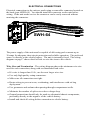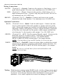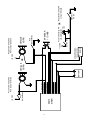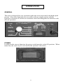
1
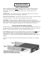
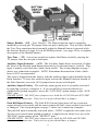
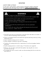
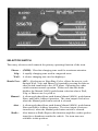
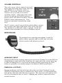
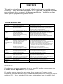
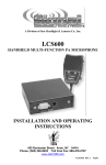
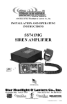
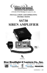
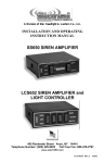
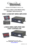
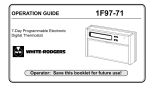
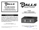
A Division of Star Headlight & Lantern Co., Inc.
SS670
SIREN AMPLIFIER
INSTALLATION AND OPERATING
INSTRUCTIONS
455 Rochester Street Avon, NY 14414
Phone: (585) 226-9025 Toll Free Fax: 888-478-2797
www.star1889.com
PLITSTR332 REV. A
12/9/05
INSTALLATION INFORMATION
SERIAL NO: _________________________
MODEL:
PURCHASE DATE: ___________________
SS670
OPTIONS
DEALER: ___________________________
_____ Two-Tone Enabled
INSTALLATION DATE: ________________
_____ Phaser/Man Auxiliary Override
INSTALLER: ________________________
_____ Phaser Disabled
Model and serial number located on bottom of unit
TABLE OF CONTENTS
GENERAL DESCRIPTION
INSTALLATION
SAFETY PRECAUTIONS
INSTALLER-SELECTABLE OPTIONS
MOUNTING
ELECTRICAL CONNECTIONS
WIRING DIAGRAM
OPERATION
GENERAL
POWER
SELECTOR SWITCH
MANUAL
HORN
VOLUME CONTROLS
MICROPHONE
AUXILIARY INPUT
PARK KILL
SERVICE
TROUBLESHOOTING
RETURNS
PARTS
SPECIFICATIONS
LIMITED WARRANTY
1
2-7
2,4
2-3
4
5-7
7
8-11
8
8
9
10
10
11
11
11
11
12-14
12
12
13
13
14
NOTICE
Due to continuous product improvements, we must reserve the right to change any specifications and information, contained in this manual
at any time without notice. Signal Vehicle Products, Inc. makes no warranty of any kind with regard to this manual, including, but not
limited to, the implied warranties of merchantability and fitness for a particular purpose. Signal Vehicle Products, Inc. shall not be liable for
errors contained herein or for incidental or consequential damages in connection with the furnishing, performance, or use of this manual.
GENERAL DESCRIPTION
The SS670 Siren Amplifier is a premium 100W unit designed for single speaker
use. The primary operating modes are Phaser, Yelp, Wail, Hands Free, Manual,
Alert, and Radio. A Noise Cancelling PA Override and push-button Horn Override
are available in all modes. A manual push-button is provided for push-on/push-off
tone toggle operation in the Phaser, Yelp, and Wail modes. It also allows manual
siren control in the Manual or Alert modes. The Phaser function can be optionally
replaced by Two-Tone or disabled entirely with program jumpers. Another feature
allows cycling through Wail, Yelp, Phaser and Standby by providing a signal to the
horn ring auxiliary wire when the function switch is in the Hands Free (HF)
position. A Park Kill option is provided for connection to a door switch, etc. to
disable the siren when exiting the vehicle. Radio and PA volume controls are
provided on the front panel. The front panel is backlighted with LED's for night
visibility. This compact unit utilizes short circuit, high voltage, low voltage, and
reverse polarity protection systems for maximum service life.
-1-
INSTALLATION
SAFETY PRECAUTIONS
Proper installation of the unit is essential for years of safe, reliable operation.
Please read all instruction before installing the unit. Failure to follow these
instructions can cause serious damage to the unit or vehicle and may void
warranties.
Qualifications - The installer must have a firm knowledge of basic electricity,
vehicle electrical systems and emergency equipment.
Keep These Instructions - Keep these instructions in the vehicle or other safe place
for future reference. Advise the vehicle operator of the location.
Unpacking - Inspect contents for shipping damage. If found, alert carrier
immediately. Contents should include unit with microphone, mounting bracket w/ 2
bolts, microphone bracket with 2 screws, wiring harness with connector and these
instructions. Contact supplier immediately if any components are missing.
INSTALLER SELECTABLE OPTIONS
The SS670 has several options that can be selected during installation. Jumpers on
the printed circuit board, inside the case, allow the installer to select these various
options. These options should be set before installation of the unit.
Cover Removal - Remove the two Philips head screws located on the back of the
unit. Slide the bottom cover back and away from the front face of the unit (see
diagram below). This cover can be removed completely from the siren unit.
CAUTION!!! DO NOT OVER-TIGHTEN THE SCREWS WHEN REPLACING
THEM.
After the cover has been removed, find the location of the jumpers (see diagram
below).
-2--
Phaser Disable – (TD – Tone Disable) The Phaser function can be completely
disabled by moving the TD jumper from one pin to both pins. This will also disable
the Two-Tone sound produced normally when the Manual button is pressed while
the Selector Knob (see page 9) is in the PHSR position. (see page 10 for a complete
description of the Manual button)
Two-Tone – (TT) A two-tone sound can replace the Phaser sound by moving the
TT jumper from the one pin to both pins.
Auxiliary Input Function – (AUX) The Auxiliary Input allows activation of either
the Horn or the Manual push-button functions by an external source (switch). This
input is usually wired into the vehicle horn switch. The wiring diagram on page 7
shows two connection examples. NOTE: Permanent disconnection of the vehicle
horn is NOT recommended.
The siren is shipped from the factory with the auxiliary input option defaulted as the
Horn function. To have the auxiliary input activate the Manual function instead of
the Horn function, move the AUX jumper from one pin to both pins.
Auxiliary Input Polarity - The auxiliary input (green wire) is normally activated
by applying a positive voltage to it. If you would like it activated when it is
connected to ground (negative), move the "AUX-POS" option jumper to the "AUXNEG" pins.
PLEASE NOTE: DO NOT place jumpers over both the AUX-POS and AUX-NEG
jumpers at the same time. Only one set of pins should have a jumper.
Park Kill Input Polarity - The Park Kill (Cutout) Input turns off any siren tone
output when it is activated, and the tones remain off until a siren control is activated
or changed. The wiring diagram on page 7 shows two connection examples.
The park kill input is normally activated when +12VDC is applied to the white wire.
To have it activated when ground (negative) is applied to the white wire, move the
"PK-POS" option jumper to the "PK-NEG” pins.
PLEASE NOTE: DO NOT place jumpers over both the PK-POS and PK-NEG
jumpers at the same time. Only one set of pins should have a jumper.
-3-
MOUNTING
SAFETY PRECAUTIONS
For the safety of the installer, vehicle operator, passengers and the community
please observe the following safety precautions. Failure to follow all safety
precautions and instructions may result in property damage, injury or death.
WARNING
• DO NOT mount in air bag deployment area.
• Devices should be mounted only in locations listed in SAE standard J1849.
• Controls should be placed within convenient reach of the driver.
• Assure clearances before drilling in vehicle.
• To prevent internal damage, mounting bolts must not enter case more
than 1/4".
• Sound levels produced by attached speakers can cause permanent
hearing loss.
• Never operate this unit without adequate hearing protection for you and
others in the area. (OSHA 1910.95)
• The SS670 siren may be mounted above the dash, below the dash, on a tunnel, or
in a rack with the mounting u-bracket provided.
• Choose a mounting location convenient to the operator and away from any air bag
deployment areas.
• Inspect behind mounting area for clearance.
• Assure adequate ventilation to prevent overheating.
• Consider wire routing and access to connections, as well as microphone bracket
placement.
• Install mounting bracket to vehicle using 1/4" hardware (not supplied).
• Drill two 1/8" size holes, and install microphone clip using the two screws
provided with the clip.
• If mounting in a rack or console, make sure that mounting bolts do not enter case
more than 1/4".
-4-
ELECTRICAL CONNECTIONS
Electrical connections to the unit are made using a removable connector located on
the back (part #SWH-64). You should install the connector on the unit before
wiring. If the unit needs service the connector can be easily removed without
unwiring the connector.
3
2
1
8
7
6
12
SWH-64
10
The power supply of the unit must be capable of delivering peak currents up to
30 amps for adequate short circuit protection and reliable operation. The preferred
source is directly at the vehicle battery. The unit is internally fused. The wiring
diagram on page 7 shows detail of how to wire the siren to the vehicle.
Wire Size and Termination - The wiring diagram shows the minimum wire size
used for each connection, along with recommended lead color.
• If a wire is longer than 10 ft., use the next larger wire size.
• Use only high quality crimp connectors.
• Make sure all connections are tight.
• Route wiring to prevent wear, overheating, and interference with air bag
deployment.
• Use grommets and sealant when passing through compartment walls.
• Minimize the number of splices to reduce voltage drop.
• Ground connections should only be made to substantial chassis components,
preferably directly to the negative of the vehicle battery.
• Install and check all wiring before connection to vehicle battery.
-5-
(Electrical Connections CONT’D)
Wiring Connections:
BLACK: (Terminal 2) – Ground: Connect to the negative of the battery, or to a
good chassis ground. Be sure to use minimum size #14 AWG wire.
RED: (Terminal 1) – Power: Connect to the positive of the battery, or to a
high current power buss. A power relay may also be used. Be sure to
use minimum size #14 AWG wire.
BROWN: (Terminals 7 & 12) – Speakers: Connect one brown wire to each
terminal or lead of the speaker. Use minimum size #14 AWG wire.
Optional Connections:
BLUE: (Terminals 3 & 6) – Radio: Used for radio repeat. Connect one blue
wire to each terminal of the radio speaker or output connector of the
radio. Most radio outputs are isolated, in which polarity would not be
important. Radios with polarity sensitive outputs should be connected
w/ the blue wire from pin 6 to the positive radio output, and the blue
wire from pin 3 to the negative radio output. Use #18 AWG wire.
GREEN: (Terminal 10) – AUX: Used for remote Manual control. Connect to the
horn ring circuit or a remote switch. Circuit may be positive or
negative with proper jumper selection. See INSTALLERSELECTABLE OPTION section (page 3) for jumper details.
NOTE: Cut lead short if not used & insulate w/ electrical tape.
WHITE: (Terminal 8) – Park-Kill: Connect to dome light or added door switch.
Circuit may be positive or negative with proper jumper selection. See
INSTALLER-SELECTABLE OPTION section (page 3) for jumper
details.
NOTE: Be sure to cut lead short if not used and insulate with
electrical tape.
3
2
1
8
7
6
12
SWH-64
10
Testing - With the siren running in the WARN mode, test the voltage across pins 1
(red) & 2 (black) of the SWH-64 connector to verify that 12.8-14.0 VDC
is present. Test all siren functions after installation to assure proper
operation. Test vehicle operation to assure no damage to vehicle.
-6-
-7-
SS670
SIREN
5 - No Connection
4 - No Connection
3 - Blue (#18 AWG)
2 - Black (#14 AWG)
1 - Red (#14 AWG)
9 - No Connection
8 - White (#18 AWG)
7 - Brown (#14 AWG)
6 - Blue (#18 AWG)
11 - No Connection
10 - Green (#18 AWG)
12 - Brown (#14 AWG)
Horn
Switch/Relay
+12 VDC
Positive Switching AUX
Horn Jumper Selected
+
BATTERY
VEHICLE
HORN
+
+
RADIO
Door Switch
Dome
Light
Positive Switching PK
Jumper Selected
SPEAKER
11 OHMS
Horn
Switch/Relay
VEHICLE
HORN
+12 VDC
Connect the Blue wires to
the terminals of speaker or
to the output jack of radio
OR
+12 VDC
Negative Switching AUX
Horn Jumper Selected
Added Door
Switch
Jumper Selected
OR Negative Switching PK
OPERATION
GENERAL
This unit is designed for easy operation under the stress associated with high-speed
pursuit. Most siren functions are accessible with one simple motion without
repetitive activation of switches or automatic timed switching that can interfere with
desired operation.
POWER
In order for the siren to function, the power switch must be in the ON position. When
turned on, the siren may be activated at the operator's discretion.
-8-
SELECTOR SWITCH
The rotary selector switch controls the primary operating function of the siren.
Phaser - (PSHR)- Ultra-fast changing tone used for maximum attention.
Yelp - A rapidly changing tone used in congested areas.
Wail - A slower changing tone used on highways.
Hands Free - (HF) - Also known as Horn Ring Cycler, allows the user to cycle
through Wail, Yelp, and Phaser by repeatedly pressing the horn or
other switch connected to the AUX input. Operating any other
switch resumes normal operation. Please note that this mode
disables the Manual (MAN) push-button selection when a Wail,
Yelp, or Phaser tone is cycled to.
Manual - A silent mode that allows push-button Manual (MAN), push-button
Horn, and Public Address operation. The siren output winds down
when the Manual push-button switch is released.
Alert - A silent mode that allows push-button Manual (MAN), push-button
Horn and Public Address operation. The siren output terminates
immediately when the Manual push-button switch is released.
Radio -
Also known as Radio Repeat, this function amplifies a radio speaker
input for re-broadcast outside the vehicle. No siren tones are
available in this position.
-9-
MAN
This momentary push-button switch provides a generally quicker changing tone
when the selector switch is in the Wail, Yelp, or Phaser positions. (See table
below). These quicker tones are used at intersections and very highly congested
areas. Pressing the button once changes to the next faster tone and pressing again
changes the tone back to the original sound. With the selector switch in the Manual,
Alert, or Hands Free position, this switch provides a manually activated Wail siren
tone while the button is being held. This is used to momentarily alert motorists or
in low noise areas.
Optional operation includes replacement of the Phaser tone with Two-Tone or
disabling the Phaser tone entirely. These options are selected during installation
and may be governed by State or Local laws.
With Rotary Switch
in this Position:
PHSR
YELP
WAIL
HF (Hands Free)
MAN (Manual)
ALERT
Pressing the MANUAL Push-button Switch
Does This:
Toggles the Output to TWO-TONE
Toggles the Output to PHASER
Toggles the Output to YELP
Creates a manual WAIL tone while button is being
held that sweeps down when the button is released.
Creates a manual WAIL tone while button is being
held that sweeps down when the button is released.
Creates a manual WAIL tone while button is being
held that stops immediately when the button is
released.
(NOTE: PHASER and TWO-TONE may be optionally swapped or disabled via
program jumpers. See INSTALLER-SELECTABLE OPTIONS on pages 2-3)
HORN (Air Horn)
This momentary push-button switch provides a simulated air-horn tone while
pressed. This can be used to either replace, or to supplement the normal vehicle
horn and is useful at intersections or in high noise areas. This tone will override all
other siren tones.
-10-
VOLUME CONTROLS
The radio repeat volume control is recessed
in the upper left hand corner of the front face.
This should be set when the vehicle is
parked. First set the volume level of the
vehicle's two-way radio to its normal
operating volume. Adjust the siren's rotary
selector switch into the RADIO position.
Insert a small, flat blade screwdriver into the
RADIO volume adjustment port. Turn
clockwise direction to increase the sound
level.
The PA volume control is provided for public address volume.
It is located in the upper right hand corner of the front face.
This should be set when the vehicle is parked. Set the PA
volume to the maximum level with no feedback (squeal).
MICROPHONE
The attached noise-canceling microphone is used for
public address operation and overrides any siren tone
when its push-to-talk button is pressed.
AUXILIARY INPUT
During installation the auxiliary input (green wire from Terminal 10 on the SWH-64
wiring harness on the back of the siren) may be connected to the vehicle horn ring
or other switching device. It provides the same operation as pressing the Horn
button or optionally (via internal jumpers) the Manual (MAN) push-button.
PARK KILL (CUTOUT)
During installation, the Park Kill input (the white wire from Terminal 8 on the
SWH-64 wiring harness) may be connected to a door switch. It will automatically
turn off any siren tone when the door is opened. The siren tone will continue to be
cut off even when the door is closed. Changing any switch or input will restore
normal function.
-11-
SERVICE
This unit is designed to provide years of reliable service under even the worst
conditions. Many times there may appear to be a problem with the unit when the
true problem is in the speaker(s) or improper installation. The following chart
shows typical symptoms and possible causes.
TROUBLESHOOTING
Symptom
No power
Possible Cause
Power switch not turned on
Connector loose
Siren 15A fuse blown
Loose connection at power source
No siren tone - PA High voltage protection
Low voltage protection
works
Microphone button stuck
Park Kill polarity option set wrong
Park Kill activated
No siren tone - No Bad speaker or speaker wiring
sound
No PA
PA volume not set properly
Distorted siren
Speaker assembly loose
sound
Intermittent Aux. Input connection
Low or high vehicle voltage
Intermittent siren High voltage protection
tone
Low voltage protection
Horn function or
Manual or Phaser
stuck on
No Radio
No or Low Radio
Wrong siren tone
Phaser not
working
Microphone button activation
Circuit breaker in supply connection
Shorted speaker or speaker wire
Horn switch stuck
MAN push-button switch stuck
Aux. Input improperly connected
Aux. Input Polarity Option set wrong
Unit not connected to radio
Radio volume too low
Radio outputs not isolated and polarity
hooked up backwards
Two-Tone option jumper installed
Aux. Input set to wrong function
Phaser disabled
Check
Does back-lighting come on?
Do you hear a "pop" when turned on?
Is power hooked up backwards? Positive ground vehicle?
Do mounting bolts protrude too far into siren housing?
Is an external fuse or circuit breaker used?
Are the negative leads connected to a good ground?
The input voltage must be less than 16 volts.
The input must be greater than 10V with the siren turned on.
Does microphone button release properly?
Is the PK jumper option properly configured?
Does the siren work when Park Kill input is disconnected?
Have you tried turning the PA volume control?
Is the speaker bell or tip loose?
Is the Aux. Input used and wired properly?
Input voltage must be between 10 & 16 volts while siren is on.
Is the vehicle voltage regulator working properly?
Is the connector tight on the back of the unit? Is there a loose
connection on a power lead? The input must be greater
than 10V with the siren turned on.
Is something lying on the microphone?
Is a circuit breaker used with at least a 30A rating?
Does the speaker have water damage, or is a wire pinched?
Does the horn switch return fully when released?
Does the MAN push-button switch return fully when released?
Is the Aux. Input used and wired properly?
Is the AUX jumper option properly configured?
Is the radio connected properly to the unit?
Can you hear the radio in the vehicle?
Have you tried turning the Radio volume control?
Are the radio wires connected to the correct polarity from the
radio output?
Is the TT jumper option properly configured?
Is the AUX jumper option configured properly?
Is the PD jumper option configured properly?
RETURNS
If you have any questions concerning this or any other SVP product, please contact our
Customer Service Department at (585) 226-9025.
If a product must be returned for any reason, please contact our Customer Service
Department to obtain a Returned Goods Authorization number (RGA#) before you ship the
product to SVP. Please write the RGA# clearly on the package near the mailing label.
-12-
PARTS
The following parts are available from Signal Vehicle Products:
Part
S30235-15
S30234-15
SWH-64
P30069-38
P30056-16
P30028-6
P30232-1
P30208-10
P30032-8
P30239-1
P30147-44P
P30050-14
Description
Siren Top Cover
Siren Bottom Mounting Plate
Wiring Harness
Microphone Bracket with Screws
1/4-20 x 3/8" Hex Locking Bolt
15 Amp Automotive Fuse
Noise Canceling Microphone
Microphone Strain Relief
TIP36C Power Transistor
Rotary Selector Switch Knob
Mounting Bracket
Case Screws
SPECIFICATIONS
Input Voltage
Input Current
Standby Current
Audio Frequency
Audio Output
Output Power
10 - 16 VDC (negative ground)
8.0 Amps @ 13.6 VDC (100W speaker)
Less than 150 mA
200Hz - 10 kHz + 3db
40 watts @13.6 VDC (100W speaker)
105 WATTS RMS MAX. (15.0 VDC - 100W speaker)
Siren Frequency
High Voltage Protection
Short Circuit Current
Operating Temperature
Controls
675Hz - 1633Hz
16 - 18 VDC will cause siren output to cease, resumes at normal voltage
30 AMPS (supply circuit must be capable of supplying this)
-15° F to +140°F
7-position rotary switch (Radio, Alert, Man, HF, Wail, Yelp, Phsr)
Momentary push-button Horn switch
Momentary push-button Manual/Toggle switch
Auxiliary input (jumper programmable) for positive or negative horn
-Remote Manual or Hands Free operation
Park Kill input (jumper programmable) for positive or negative activation
Phaser (and Two-Tone) disable (jumper programmable)
Two-Tone activation (swaps modes with Phaser) (jumper programmable)
Detachable, 12-pin, positive locking connector with pigtail leads.
(1) Positive, (1) Negative, (2) Speaker, (2) Radio, Auxiliary, Park Kill
6" Wide, 6-1/2" Deep, 2" High
6 lbs.
Connections
(12-Pin Connector)
Size
Shipping Weight
-13-
LIMITED WARRANTY
Signal Vehicle Products warrants this new product to be free from defects in
material and workmanship, under normal use and service, for a period of one (1)
year from the date of delivery to the first user-purchaser.
During this warranty period the obligation of Signal Vehicle Products is limited to
repairing or replacing, as Signal Vehicle Products may elect, any part or parts of
such product which after examination by Signal Vehicle Products is determined to
be defective in material and/or workmanship.
This warranty does not cover labor charges for removal or re-installation of the
product. Fuses and lamps are not covered under this warranty.
This warranty does not extend to any unit that has been subjected to abuse, misuse,
improper installation or which has not been adequately maintained, nor to units
which have problems related to service or modification at any facility other than the
manufacturer.
THERE ARE NO OTHER WARRANTIES, EXPRESSED OR IMPLIED,
INCLUDING BUT NOT LIMITED TO, ANY IMPLIED WARRANTIES OF
MERCHANTABILITY OR FITNESS FOR A PARTICULAR PURPOSE. IN NO
EVENT SHALL SIGNAL VEHICLE PRODUCTS BE LIABLE FOR ANY LOSS OF
PROFITS OR ANY INDIRECT OR CONSEQUENTIAL DAMAGES ARISING OUT
OF ANY SUCH DEFECT IN MATERIALS OR WORKMANSHIP.
A Division of Star Headlight & Lantern Co., Inc.
455 Rochester Street Avon, NY 14414
Phone: (585) 226-9025 Toll Free Fax: 888-478-2797
www.star1889.com
-14-