1
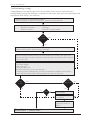
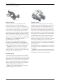
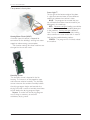
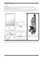
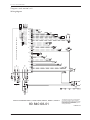
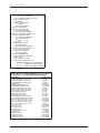
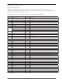
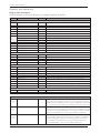
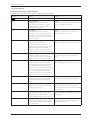
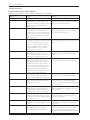
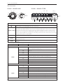
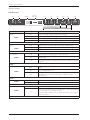
Service manual
Dishwasher - DW90
Service manual DW90
2
Service manual
Contents
Type: DW90
Updates...................................................................................................................................................................................................................................................4
Introduction..........................................................................................................................................................................................................................................5
Troubleshooting strategy .............................................................................................................................................................................................................6
Types.........................................................................................................................................................................................................................................................7
Technical data.......................................................................................................................................................................................................................................8
Component description................................................................................................................................................................................................................9
Components and measurement values..........................................................................................................................................................................9
Components and function description ...................................................................................................................................................................... 10
Programs and control unit........................................................................................................................................................................................................ 18
Wiring diagram ......................................................................................................................................................................................................................... 18
Program flow description.................................................................................................................................................................................................... 20
Troubleshooting............................................................................................................................................................................................................................... 22
Dishwashing results ................................................................................................................................................................................................................ 22
Common faults........................................................................................................................................................................................................................... 22
Water level DW90................................................................................................................................................................................................................... 23
Fault indicators........................................................................................................................................................................................................................... 24
Fault and information codes............................................................................................................................................................................................... 25
DW90.1.................................................................................................................................................................................................................................... 25
DW90.2.................................................................................................................................................................................................................................... 26
DW90.3.................................................................................................................................................................................................................................... 27
Service menu and settings......................................................................................................................................................................................................... 28
Service menu DW90.1.......................................................................................................................................................................................................... 28
Service menu DW90.2.......................................................................................................................................................................................................... 30
Service menu DW90.3.......................................................................................................................................................................................................... 32
Settings............................................................................................................................................................................................................................................ 34
Tools.................................................................................................................................................................................................................................................. 34
Special tools................................................................................................................................................................................................................................. 34
Service and installation................................................................................................................................................................................................................ 36
Increased working space during service...................................................................................................................................................................... 36
Overflow guard wiring........................................................................................................................................................................................................... 37
Service manual DW90
Updates
Rev
Date
Description
Initials
01
2011-04-15
First version
FH
02
2011-05-12
Front display 90.2, service menu 90.1 and 90.2 and also some minor text updates
FH
03
2011-05-27
90.1 OTHER included
FH
04
2011-06-08
Instruction for ”Increased working space during service” updated
FH
05
2011-11-29
Updated wiring diagram and added information about Anti siphon
ISC
06
2012-02-02
Updated service menu for 90.2. Changed description how to set TDE & HWC.
AN
07
2012-03-16
Instructions updated for 90.2. Store program added.
EH
08
2012-04-23
Service menu for 90.2 updated. Description added for Total reset (TDE & HWC).
EH
09
2012-05-21
Information for Region settings updated.
EH
10
2012-09-06
Program flow description for the Daily wash program included.
EH
4
Service manual DW90
Introduction
You are holding the Service manual for the DW90 generation of dishwashers.
The DW90 dishwasher series is available in three different basic models, designated DW90.1,
DW90.2 and DW90.3. In the Types section, we present the various panels found on each type,
making it easy to identify the different machines. The different models are named differently in
different markets. The type designation is most important when identifying a particular machine
model. This information can be found on the serial number plate on the right of the inside of the
door, where the machine’s model designation is specified.
TYPE
Typbeteckning
Modellnamn
Artikelnummer
MODEL
SERIAL NO
Model D5454
The first two digits of the serial number specify the year of manufacture
while the third and fourth digits specify the week of manufacture. The
remaining digits form the sequential number.
Löpnummer
År Vecka
It should be easy to service a dishwasher. It is important that you, as a service
technician,
are
afforded conditions that enable you to work in an efficient and satisfactory way. Our hope is that
this service manual will prove a useful tool in your daily work.
Asko Appliances AB
SE-534 82 Vara
Sweden
OPERATING INSTRUCTIONS
Always have the operating instructions for the machine available during service
5
Service manual DW90
Troubleshooting strategy
Troubleshooting is an important part of the service callout, and as such we have drawn up a
troubleshooting strategy that describes, in broad terms and step by step, what you need to do to find
and diagnose faults arising in our machines.
• Ask the customer to describe the problem.
• Check whether the customer’s description matches the reported fault.
• Check that the machine is correctly installed:
- Electrical connection
- Drainage
- Water connection
- Machine correctly levelled
Fault
found?
No
Yes
Incorrect installation or external factors that affect performance and functionality (for
example, water pressure, electrical supply, drainage).
The machine operates normally. No deviations can be found. The customer probably
needs to be informed about proper use of the machine. If necessary, also inform the
customer about the warranty conditions and the fact that the customer will be charged
for the service call.
Open the service menu:
1. Check the settings
2. Run a test cycle
3. Note any fault codes
If the above actions do not uncover the fault:
• Conduct general troubleshooting. Use the documentation available at ServiceSaver
(service manuals, service memos, wiring diagrams and other documents).
Fault
found?
No
Fault
diagnosed?
Yes
Yes
Yes
OK?
No
Repair and check
function/safety.
Contact technical support
for assistance.
Carry out the actions
suggested by technical
support.
Satisfied customer!
6
No
Service manual DW90
Types
DW90.1 - BRAND ASKO
The machine has 6 set programs and 2, 3 or 5 options that can vary depending on the variant.
The touch buttons and display are found on the front of the panel. The main power switch is on
the top.
START
STOP
PROG
DW90.2
The machine has 9 set programs, but can be specified with up to 16 programs. The touch buttons
and display are usually found on the top. Certain variants are supplied with a display on the front.
Display on the front
DW90.3
The machine has 16 set programs and the touch buttons and display are on the top. The number
of options and settings vary depending on the specification of the machine.
PROG
S TA R T
STOP
DW90.1
- BRAND
OTHER
5454 Variant
6OEM
Auto + Time Saver - DW90.1PanelCylinda5OptionsAutoProgrammeTimeSaver
The machine has 6 set programs and 2, 3 or 5 options that can vary depending on the variant.
The touch buttons and display are found on the front of the panel. The main power switch is on
the top.
7
Service manual DW90
Technical data
Height:
Width:
Depth:
Weight (freestanding):
Weight (integrated):
Water pressure:
Connection:
Max. rated power:
823-870 mm (32-1/4” to 35-1/2”) = for 820 mm machines (XL)
863-910 mm (33-3/4” to 36”) = for 860 mm machines (XXL)
596 mm (23-5/8”)
550 mm (22”)
56 kg/59 kg (124 lbs/130 lbs) with water softener (XL)
57 kg/60 kg (126 lbs/132 lbs) with water softener (XXL)
49 kg/52 kg (108 lbs/115 lbs) with water softener (XL)
50 kg/53 kg (110 lbs/117 lbs) with water softener (XXL)
0.03–1.0 MPa (0.3–10 kp/cm2) (4.2-140 psi)
1-phase, 230 V, 50/60 Hz, (10 A/16 A)**
1-phase, 120 V, 60 Hz, (15 A)**
3-phase, 400 V, 50/60 Hz, (10 A) **
1700 W (230 V)**
1300 W (120 V)**
2200 W (400 V)**
* According to EN 50242 standard.
** See type plate.
8
Service manual DW90
Component description
Components and measurement values
The specified resistance values apply at room temperature (about 20°C/68°F)
Values within ±10% are considered normal.
Article no. Position Component
8073779
8083041
8079504
8079505
8078096
8083094
8083095
8078080
EMC-filter with inductor
Filter with screwplint
Heating element 1600 W 230 V
Heating element 1200 W 120 V
Thermistor
Combi disp. 230 V
Combi disp. 120 V
Circ.pump 220-240 V 50 Hz,
47 L (12.4 gallon)/min
Circ.pump 220-240 V 50 Hz
8078080
Measurement
value
Primary winding
680 kohm
1 Mohm
32 ohm
12 ohm
60 kohm
1,32 kohm
285 ohm
115 ohm
Auxiliary winding
260 ohm
8078082
Circ.pump 120 V 60 Hz,
47 L (12.4 gallon)/min
Primary winding
31,4 ohm
8078082
Circ.pump 120 V 60 Hz
Drain pump 200-240 V 50 Hz,
16 L (4.2 gallon)/min
Drain pump 120V 60 Hz,
16 L (4.2 gallon)/min
Spray arm diverter 230 V 50/60 Hz
Spray arm diverter 120 V 60 Hz
Inlet valve single 200-240 V,
4 L (1 gallon)/min
Inlet valve single 120 V,
4 L (1 gallon)/min
Inlet valve security 220-240 V,
4 L (1 gallon)/min
Inlet valve security 120 V,
4 L (1 gallon)/min
Water softener salt valve 220-240 V
Water softener mix valve 220-240 V
Auxiliary winding
76 ohm
148 ohm
8078087
8078089
8078084
8078085
8079502
8079503
8079500
8079501
8078090*
8078090*
8078302*
8078302*
8073830
8084147
8089578
8089580
2-3
2-3
Water softener salt valve 120 V
Water softener mix valve 120 V
Halogen lamp 5 W/12 V
Thermo Actuator 110-240 V
Fan motor 230 V
Fan motor 120 V
26 ohm
8,5 kohm
2,6 kohm
3,9 kohm
0,95 kohm
2 kohm
0,5 kohm
3 kohm
2,33 kohm
0,65 kohm
0,65 kohm
<10 kohm
0,85-1,2 kohm
0,85 kohm
185 ohm
* The number is for a complete water softener; replacement salt and mixer valves are not available separately.
9
Service manual DW90
Component description
Components and function description
Here we describe the function and
specification of the most important
components. Certain components are found
only in more highly specified machines or in
particular markets. See the Troubleshooting
section for fault and information codes.
CU, Control Unit
The CU, or Control Unit, is a unit that functions
as both a control panel and a logic component.
The control panel is fitted with a display and touch
buttons for selecting programs, options and Start/
Stop. The control panel is an integrated part of
the CU and cannot be replaced separately. The
logic component manages functions needed for
dishwashing programs and diagnosis. The CU
has an internal power supply for the logic. In the
event of a fault, the CU can diagnose a number of
components and functions and display fault codes.
To facilitate troubleshooting the service menu
includes a component diagnostics function, which
activates the outputs in a particular sequence.
Accelerometer
The control unit in DW90.2 contains an accelerometer,
a sensor that senses position and acceleration. It controls
the touch buttons and the brightness of the light. The
accelerometer turns off at a specific angle to avoid causing
a distraction when seen from the worktop. It is calibrated
when the door is closed.
If this symbol appears on the display
the door is not open enough. Open
the door until the display lights up.
Inlet valve
The inlet valve has an electrical connector
that is coded to ensure it is not mixed up. It is
fitted with a filter, which can be removed for
cleaning. Both single and safety valves are used
as inlet valves. The inlet valve contains a filter
to stop particles then a flow limiter to limit
the flow to a maximum of 4 L (1 gallon)/min.
It opens when the water pressure exceeds 0.3
bar (4.3 psi) and provides full flow at about 2
bar (29 psi). It has a pressure range of 0.3 bar
(4.3 psi) to 10 bar (145 psi). The inlet valve is
fitted to the air gap and can be replaced from
the rear of the machine.
Purpose: To ensure that the machine
is supplied with water for the different
dishwashing cycles.
Safety valve
The safety valve has two independent valve seats,
each controlled by a separate electromagnet. The
valve seats are connected in series. This doubles
the safety factor. The electromagnets are also
connected in series (electrically), which means each
magnet’s rated voltage is half the mains voltage (e.g.,
a 230 V valve = 2 x 115 V coils)
Single valve
The single valve comprises an electromagnet
and a valve seat.
10
Service manual DW90
Component description
Flow meter
Flow meter
The flow meter is fitted in the air gap and
cannot be replaced separately. It comprises an
impeller that is rotated by the flow of water
from the inlet valve. The impeller is fitted with
two magnets that affect a sensor, a so-called
reed switch. This is connected to the control
unit via a wire and provides the control unit
with information on the amount of water
entering the machine. In order for the flow
sensor to function normally the incoming
water pressure must be at least 2 bar (29 psi).
Output signal: 220 pulses per liter (0.26 gallon)
of water flowing through.
Circulation pump
The circulation pump comprises an asynchronous
motor with a capacitor and a pump housing with
an impeller. The impeller and seals cannot be
replaced separately, rather the entire pump must
be replaced. The circulation pump can be rated
220-240V, 50/60Hz, as well as 120V, 60Hz.
Purpose: To provide the spray system with the
water pressure necessary for the dishwashing
process.
Spray arm diverter
The spray arm diverter is under the spray arm hub
on the underside of the cleaning compartment.
The water from the circulation pump flows
through the spray arm diverter, which alternates
the flow of water between the upper and lower
spray arms. The spray arm diverter comprises a
synchronous motor that drives a disc valve. The
disc has a smaller opening and a larger opening and
as it rotates it distributes the water to the spray
arms at low or high pressure. Information on the
disc position is sent to the control unit. The spray
arm diverter is calibrated when the main power
switch is turned on.
Purpose: To distribute spray water to the spray
arms in accordance with the program specification.
Heating element
The heating element is of the flow-through
type and is fitted between the bottom drain
and the suction connector of the circulation
pump. It comprises a pipe with a heating coil.
One side of the heating coil is fitted with an
overheating cut-out with a trigger temperature
of 98°C (208°F) and an automatic reset. The
other side is fitted with a safety fuse that blows
at 229°C (444°F). The element is replaced
from the rear of the machine by first moving
the circulation pump out of the way.
Purpose: To heat the dishwater to the correct
temperature during the prewash/main wash and
final rinse.
11
Service manual DW90
Component description
Drain pump
The drain pump is fitted to the bottom drain and
can be replaced from the front of the machine. In
the bottom drain, under the filters, is a cleaning
plug which when removed enables the customer
to clean the pump housing. In the event of a
blockage the pump changes its direction of
rotation to try to clear the blockage.
Purpose: To drain the water from the cleaning
compartment in accordance with the program
specification and in case of overflow.
Detergent and rinse aid dispenser
The dispenser has one container for detergent
and one container for rinse aid. The containers
are opened by activating the electromagnet
found on the lock of each container. When
first activated detergent is dispensed and when
activated a second time rinse aid is dispensed.
A weight (which is activated when the door
is opened for loading and unloading) resets
the mechanism so that the dispenser always
dispenses detergent first when a new program
is started.
12
Fan
The fan is fitted to the top edge of the inner
door and comprises a fan motor, a fan housing,
a venting duct, a double-sided impeller, a
damper and a Wax motor that controls the
damper function. The fan works throughout
most of the dishwashing program in order to
reduce the formation of condensation between
the machine’s inner and outer doors and to
eliminate condensation between the outer door
and the cover door on fully integrated machines.
During the drying program the fan sucks in
cold, dry air from outside via the duct in order
to cool it. The Wax motor opens the damper
slowly allowing the fan to suck in the hot, damp
air from the cleaning compartment. The two air
flows are mixed in the duct where the moisture
condenses into water that is routed into the
cleaning compartment. The air is vented through
a nozzle under the outer door.
Purpose: To vent the hot, damp air from
the cleaning compartment so that the dishes
dry during the drying program and to prevent
condensation forming between the machine’s
inner and outer doors.
Cables
The machine is fitted with coded connectors
to prevent incorrect wiring. The cables comply
with the Rast 2.5 and Rast 5 standards.
Service manual DW90
Component description
Turbo Drying Express (TDE)
Certain machines are equipped with Turbo Drying
Express, which provides more efficient drying,
among other things. Hot air is blown into the cleaning
compartment and used for drying and warming
crockery. The air is vented by the normal fan.
Door switch
A micro switch detects when the door has been
opened. The program is paused and power to
certain components (circulation pump, valves
and more) is cut. The program continues where
it left off when the door is closed. If a program
is running the machine indicates that the door is
open.
Purpose: To prevent the machine from running
while the door is open.
The nozzle that blows the hot air is fitted to the
side wall of the cleaning compartment.
Main power switch
The main power switch has 2 pins and breaks the
phase and the earth. However, power to the filters,
overflow guard, drain pump and inlet valve is not
cut when the main power switch is turned off.
On the DW90.2 the main power switch is
electronic and is integrated with the control unit.
The machine switches to standby when the main
power switch is deactivated and when the door is
closed. Standby is deactivated when the main power
switch is activated and when the door is opened.
EMC filter with inductor
The filter is fitted at the front of the bottom
plate and consists of a number of coils,
condensers and resistors.
Purpose: To eliminate electromagnetic
interference to and from the machine.
Water softener
Certain machines are fitted with a water
softener. The water softener is under the cleaning
compartment and has a cap for topping up the salt in
the bottom of the cleaning compartment. The water
softener has two chambers, one for salt and one for
ion exchange resin. It also has two electromagnetic
valves (a mixer valve and a salt valve) which control
the water flow to the salt chamber and through
the ion exchange resin. When filling with water,
the water flows through the chamber containing
the ion exchange resin where the hard water is
softened. The mixer valve is used to control whether
the incoming water flows through or bypasses the
chamber containing ion exchange resin depending
on the water hardness setting. The salt valve is used
to fill the chamber containing the ion exchange resin
with water saturated with salt from the salt chamber
when the ion exchange resin needs to be recharged.
When the salt valve opens the water pocket in the
air gap is emptied, with the water passing through the
salt chamber and into the chamber containing the ion
exchange resin.
13
Service manual DW90
Component description
Air gap
The air gap is found next to the cleaning
compartment. It comprises channels through
which the incoming water flows into the
cleaning compartment. These channels also
contain an anti-backflow device and the
flow sensor through which the water passes.
Certain models are equipped with a water
pocket that collects water used for the water
softener (only machines with a water softener).
The air gap also works as a channel of air taken
in during the drying phase, as well as a pressure
relief for excess air when opening and closing
the door. On machines with Turbo Drying
Express (TDE) a lid is mounted on the inside
of the air gap. If there is condensation in the
kitchen interiors, make sure the lid is correctly
fitted.
Purpose: To prevent dirty water from the
cleaning compartment being sucked back into
the water supply, and lead air to and from the
container.
14
Thermistor
The thermistor for temperature measurement
is located at the front edge of the bottom
drain. The thermistor measures and controls
the water temperature, which can be up to
70°C (158°F). If the thermistor short-circuits or
loses contact with the CU, or of the thermistor
does not register a temperature increase of
5°C (41°F) within 10 minutes of the element
being activated, the element is switched off and
a fault code is indicated. This is only indicated
in the service menu. The thermistor is of the
NTC type (Negative Temperature Coefficient),
i.e. its resistance decreases as temperature
increases.
Purpose: To control the water temperature during
the dishwashing process.
Light
The light is a 5 W/12 V halogen bulb powered
by the control unit via a micro switch. The
lamp is activated when the door is opened
more than 5° and automatically deactivated
when the door has been open for more
than 30 minutes. The control unit features
protective components that limit the current
to the light in case of a short circuit or if a bulb
with too high a power rating is fitted. The
bulb can be replaced from inside the cleaning
compartment.
Service manual DW90
Component description
Pressure sensor
The pressure sensor is connected to the
pressure chamber in the bottom drain. It
measures the pressure, which corresponds to
the water level in the machine. If the water level
in the machine is too high (for five consecutive
seconds) the drain pump starts and all other
components are switched off. When the correct
level is reached, the program continues where
it left off. If the level sensor generates an output
signal of <1 VDC during the prewash (indicating
a blocked filter), an additional prewash is
activated with an SCS step.
The level sensor also controls the draining
time (can be extended from 20 seconds to a
maximum of 2 min). The sensor also checks the
need to refill (such as if a bowl fills with water).
Purpose: To prevent overflow, to detect
a ‘blocked filter’, to when necessary refill the
machine (such as if a bowl has filled with water)
and to control the draining time.
Turbidity sensor
Machines with an auto program have a turbidity
sensor that measures how cloudy the water is. The
sensor comprises an LED and a phototransistor.
Between these two is the dishwater. The less light
that reaches the phototransistor, the cloudier the
water. The sensor is calibrated during the last rinse
of the auto program. At different points during the
auto program the output signal from the turbidity
sensor provides data used to determine how the
program will continue (number of prewashes,
temperature, program time, number of rinses and
so on). If the turbidity sensor fails, the machine
assumes the water is “very cloudy”, which results in
a longer program time, with prewashes, additional
rinses and so on.
The turbidity sensor is located at the front edge of
the bottom drain and is replaced from the front of
the machine.
Purpose: To sense how dirty the dishes are and
to provide the control unit with information about
which program is best suited to the dishes.
Overflow guard
The overflow guard is integrated with the bottom
drain. This overflow guard consists of a micro switch
activated by a float if water collects on the machine’s
bottom plate. The micro switch is normally closed.
When it is activated, it breaks the circuit to the CU,
the drain pump starts, the program is interrupted
and the machine indicates an overflow.
Purpose: To provide protection from any water
leaks or flooding from the machine.
15
Service manual DW90
Component description
Heating Water Circuit (HWC)
A certain type of machine is adapted for
connection to the building’s existing hot water
supply to reduce energy consumption.
The function settings for these machines are
changed via the service menu.
Humidity sensor
The humidity sensor is located in the fan
housing. The sensor is of the capacitive type
and measures relative humidity. The humidity
sensor measures the ambient humidity before
the drying program begins and controls the
drying time until it senses a humidity level close
to that before the drying program began.
Purpose: To make sure the drying program
runs as long as necessary to ensure a
satisfactory drying result.
16
Status Light™
To the right at the bottom edge of the door
is a light that communicates in three different
colours to indicate the machine’s status.
BLUE - The program has started, but you
can still load more dishes into the machine (no
detergent in the machine).
RED - Constant red light; loading more dishes
into the machine not recommended (detergent
in the machine). Flashing red light indicates a
fault. This can mean a water inlet fault, leaking
valve, overflow or water outlet fault. In case of
fault, see the troubleshooting section.
GREEN - The program has finished, unload
the machine.
Service manual DW90
Component description
Anti siphon
Dishwashers equipped with Anti-Siphon device can be installed in an elevated installation.
The drainage hose can run to a lower level than the bottom of the dishwasher without emptying the
dishwasher of water during the wash cycle.
The Anti-Siphon device acts as a pressure equalizer which ensures that over- or under-pressure never
occurs in the machine. This prevents the machine from either being emptied of water or sucking water
from the drain. As an extra security measure the drain hose is fitted with a check valve.
The anti-siphon device is placed
on the left side of the dishwasher.
The drainage hose may be extended by a maximum of 3m (the total length of the drainage hose
must not exceed 4,5m). Any joins and connecting pipes must have an internal diameter of at least
14mm.
17
18
80 840 68-01
7
MV
HL
GS TS FM SG NTC
7
TS
8 9
PS
CIRCUIT DIAGRAM DW90.1, DW90.1OEM, DW90.2, DW90.C, DW90.3
SS
TH
1/C
2
PS
1 23
IS
FM
SS
TH
HS
UART
This document must not be copied without
our written pemission, and the contents
thereof must not be imparted to a third party
nor be used for any unauthorized purpose.
Contravention will be prosecuted.
Asko Appliances AB
SL
DW90.1, DW90.1OEM, DW90.2, DW90.C, DW90.3
FM
IS
1/C
80 840 68-01
8 9
GS TS FM SG NTC
SL
CIRCUIT DIAGRAM DW90.1, DW90.1OEM, DW90.2, DW90.C, DW90.3
HL
6
BE
UART
HS
C
20V
30V
120V
230V
1 23
L
DIV M
N
DIV M
5
DIV
6
IV
MV
MV
BE
FS
CP
SV
4
5
RAS
SV
DIV
F
DP
CP
3
CP IV
MV
I2C
CP
IV
4
DS
VAX
VAX
VAX
SV
CD
FN 1
FL
3
HE
DS
CP IV
PENSER 120V
PENSER 230V
PUMP 120V 60HZ
PUMP 230V 50HZ
PUMP 220V 60HZ
20V 60HZ
30V 50HZ
30V 60HZ
IVIDER 120V 60HZ
IVIDER 230V 50/60HZ
INGLE INCL. 120V
AFETY INCL. 120V
INGLE INCL. 230V
AFETY INCL. 230V
20V
V
30V
V
P 5W 12V
FS
DR
2
KD
VAX
RESISTANCE
1 MOHM
12 OHM
32 OHM
25 OHM
60 KOHM
0,28 KOHM
1,32 KOHM
32 OHM
110 OHM
56 OHM
25 OHM
150 OHM
85 OHM
2.6 KOHM
8,5 KOHM
0.95 KOHM
0.5 KOHM
3,9 KOHM
2 KOHM
0,65 KOHM
0,65 KOHM
3 KOHM
2,3 KOHM
<10 KOHM
1.1 KOHM
0.18 KOHM
0,85 KOHM
0,22 KOHM
0,90 KOHM
CD
LB
FN 1
VMG
FL
ERENCE SUPPRESSION FILTER
ENT 1200W 120V
ENT 1600W 230V
ENT 2040W 230V
1
HS
2
AP
I2C
KD
HE
10
SL
DW90.1, DW90.1OEM, DW90.2, DW90.C, DW90.3
LB
EL
TB
14
10
HS
S AT ROOM TEMPERATURE (CA. 20°C/68°F)
+/-10% ARE REGARDED AS NORMAL
MS
RAS
3/4
1/C PTC
FAN
VMG
HE (PTC)
FN2
DP
TDE
1
2
HWC
AP
OMBI DISPENSER
IRCULATION PUMP
ATER DIVERTER VALVE
RAIN PUMP
OOR
OOR SWITCH
LTER
OW METER
N DOOR
N BOTTOM
OAT SWITCH
EATING ELEMENT
EATING ELEMENT PTC
ALOGEN LAMP
UMIDITY SENSOR
LUM. SWITCH
LET VALVE
C
AIN SWITCH
IX VALVE
ESSURE SENSOR
INSE AID SENSOR
ATUS LIGHT
LT SENSOR
LT VALVE
ERMISTOR
RBIDITY SENSOR
ART
X ACTUATOR
OT WATER CIRCUIT
WIRES IN ALL MACHINES
INTERNAL CONNECTION
WIRES IN SOME MACHINES
3/4
EL
SL
1/C
C)
3/4
TB
14
2
PTC
3/4
FAN
1/C
1/C
Service manual DW90
Programs and control unit
Wiring diagram
SV
TS
2
This document must not be copied without
our written pemission, and the contents
thereof must not be imparted to a third party
nor be used for any unauthorized purpose.
Contravention will be prosecuted.
Asko Appliances AB
FORMAT A4
Service manual DW90
HWC
KD/CD: COMBI DISPENSER
CP: CIRCULATION PUMP
DIV: WATER DIVERTER VALVE
AP/DP: DRAIN PUMP
DR: DOOR
LB/DS: DOOR SWITCH
F: FILTER
FM: FLOW METER
FL/FN 1: FAN DOOR
FAN/FN 2: FAN BOTTOM
FS: FLOAT SWITCH
EL/HE: HEATING ELEMENT
HE (PTC): HEATING ELEMENT PTC
BE/HL: HALOGEN LAMP
HS: HUMIDITY SENSOR
IS: ILLUM. SWITCH
IV: INLET VALVE
I2C: I2C
TB/MS: MAIN SWITCH
MV: MIX VALVE
TS/PS: PRESSURE SENSOR
VMG/RAS: RINSE AID SENSOR
SL: STATUS LIGHT
SG/SS: SALT SENSOR
SV: SALT VALVE
NTC/TH: THERMISTOR
GS/TS: TURBIDITY SENSOR
UART: UART
VAX: VAX ACTUATOR
HWC: HOT WATER CIRCUIT
WIRES IN ALL MACHINES
INTERNAL CONNECTION
WIRES IN SOME MACHINES
FN2
F
TDE
P
HE (PTC)
T
MS
E
HE
1
V
AP
RESISTANCES AT ROOM TEMPERATURE (CA. 20°C/68°F)
VALUES WITH +/-10% ARE REGARDED AS NORMAL
DR
DP
HE
CP
F
N
3/4
RESISTANCE
1 MOHM
12 OHM
32 OHM
25 OHM
60 KOHM
0,28 KOHM
1,32 KOHM
32 OHM
110 OHM
56 OHM
25 OHM
150 OHM
85 OHM
2.6 KOHM
8,5 KOHM
0.95 KOHM
0.5 KOHM
3,9 KOHM
2 KOHM
0,65 KOHM
0,65 KOHM
3 KOHM
2,3 KOHM
<10 KOHM
1.1 KOHM
0.18 KOHM
0,85 KOHM
0,22 KOHM
0,90 KOHM
1/C
COMPONENT
RADIO INTERFERENCE SUPPRESSION FILTER
HEATING ELEMENT 1200W 120V
HEATING ELEMENT 1600W 230V
HEATING ELEMENT 2040W 230V
THERMISTOR
COMBINED DISPENSER 120V
COMBINED DISPENSER 230V
CIRCULATION PUMP 120V 60HZ
CIRCULATION PUMP 230V 50HZ
CIRCULATION PUMP 220V 60HZ
DRAIN PUMP 120V 60HZ
DRAIN PUMP 230V 50HZ
DRAIN PUMP 230V 60HZ
SPRAY ARM DIVIDER 120V 60HZ
SPRAY ARM DIVIDER 230V 50/60HZ
INLET VALVE SINGLE INCL. 120V
INLET VALVE SAFETY INCL. 120V
INLET VALVE SINGLE INCL. 230V
INLET VALVE SAFETY INCL. 230V
SALT VALVE 120V
MIX VALVE 120V
SALT VALVE 230V
MIX VALVE 230V
HALOGEN LAMP 5W 12V
WAX MOTOR
FAN MOTOR 120V
FAN MOTOR 230V
FAN MOTOR 2 120V
FAN MOTOR 2 230V
FS
L
C
19
Service manual DW90
Programs and control unit
Program flow description
If the component test in the service menu is not sufficient to identify a fault you can run a
program and compare the results with the flow description below. If they are in agreement this
indicates a correctly functioning control unit.
Presented below is the Daily wash program, no options selected (DW90.1).
Step
Component
Prewash
1
Drain process
2
3
4
5
6
If ECO is
set
7
8
9
Inlet process
Circ. pump
Pause
Circ. pump
Pause
Circ.pump
Drain process
Inlet process
Circ.pump
Pause
Circ.pump
Time
Comment
6 sec 12-16 sec when restarting or if an earlier program was interrupted
255 sec
3 sec
30 sec
30 sec
5 sec
120 sec
120 sec
255 sec
360 sec
5 sec
150 sec
Maximum time. Inlet time is controlled by a flow meter**
If water temperature is >30°C ECO program starts (DW90.1)
Maximum time. Time is controlled by level sensor***
Maximum time. Inlet time is controlled by a flow meter**
If the level sensor indicates under IV the drain process will be
interrupted earlier.
90 sec Maximum time 90 sec. Minimum time 76 sec*
120 sec Maximum time. Time is controlled by level sensor***
10
Cleaning cycle for container
11
Drain process
Main wash
12
Inlet process
255 sec Maximum time. Inlet time is controlled by a flow meter**
13
Circ. pump + Combi dispenser
10 sec
14
Circ. pump + Element
60°C
15
Circ. pump
1560 sec
16
Cleaning cycle for container
90 sec Maximum time 90 sec. Minimum time 76 sec*
17
Drain process
120 sec Maximum time. Time is controlled by level sensor***
1:st rinse
18
Inlet process
255 sec Maximum time. Inlet time is controlled by a flow meter**
19
Cleaning cycle for container
90 sec
20
Drain process
120 sec Maximum time. Time is controlled by level sensor***
2:nd rinse
21
Inlet process
255 sec Maximum time. Inlet time is controlled by a flow meter**
22
Circ. pump
240 sec
23
Cleaning cycle for container
90 sec Maximum time 90 sec. Minimum time 76 sec*
24
Drain process
120 sec Maximum time. Time is controlled by level sensor***
3:rd rinse
25
Inlet process
255 sec Maximum time. Inlet time is controlled by a flow meter**
26
Circ. pump + Element
65°C
27
Circ. pump + Combi dispenser
10 sec Pulses (varies depending on the setting of rinse aid)
28
Circ. pump
300 sec
29
Pause
60 sec
30
Drain process
120 sec Maximum time. Time is controlled by level sensor***
Drying
31
Fan
480 sec
32
Signal
4 sec If signal is selected
20
Service manual DW90
Programs and control unit
Program flow description
Presented below is the Quick program, no options selected (DW90.1).
Step
Component
Main wash
1
Drain process
2
3
4
5
6
If ECO is
set
7
8
9
10
11
1:st rinse
12
13
14
15
16
2:nd rinse
17
18
19
20
3:rd rinse
21
22
23
24
25
Drying
26
27
Time
Comment
6 sec 12-16 sec when restarting or if an earlier program was interrupted
Inlet process
Circ. pump
Pause
Circ. pump
Pause
Circ.pump
Drain process
Inlet process
Circ. pump + Combi dispenser
Circ. pump + Element
Circ. pump
Cleaning cycle for container
Drain process
255 sec
3 sec
30 sec
30 sec
5 sec
120 sec
120 sec
255 sec
10 sec
Inlet process
Circ. pump
Pause
Circ. pump
Drain process
255 sec Maximum time. Inlet time is controlled by a flow meter**
3 sec
5 sec
3 sec
120 sec Maximum time. Time is controlled by level sensor***
Inlet process
Circ. pump
Cleaning cycle for container
Drain process
255 sec Maximum time. Inlet time is controlled by a flow meter**
150 sec
90 sec Maximum time 90 sec. Minimum time 76 sec*
120 sec Maximum time. Time is controlled by level sensor***
Inlet process
Circ. pump
Circ. pump + Element
Circ. pump + Combi dispenser
Drain process
255 sec Maximum time. Inlet time is controlled by a flow meter**
60 sec
60°C
10 sec Pulses (varies depending on the setting of rinse aid)
120 sec Maximum time. Time is controlled by level sensor***
Fan
Signal
480 sec
4 sec If signal is selected
Explanations
Cleaning Cleaning cycle for container
process
*
Inlet
Inlet process
process
**
Drain Drain process
process
***
Maximum time. Inlet time is controlled by a flow meter**
If water temperature is >30°C ECO program starts (DW90.1)
Maximum time. Time is controlled by level sensor***
Maximum time. Inlet time is controlled by a flow meter**
60°C If ECO 30°C
30 sec
90 sec Maximum time 90 sec. Minimum time 76 sec*
120 sec Maximum time. Time is controlled by level sensor***
90 sec The circ. pump stops and the drain pump runs for 2 sec. The circ.
pump runs for 3 sec. and then rests for 5 sec. In total this is repeated
eight times, but the fifth time the circ. pump is resting for 8 sec instead
of 5 sec, when spray arm diverter is switching to the upper spray arm.
255 sec A flow meter signals the flow in pulses. The control unit (CU)
determines how many pulses to be calculated for each inlet. If not 80
pulses has been reached within 60 sec or a specific number of pulses
is not reached within 255 sec, the program will be interrupted.
120 sec The drain pump starts and pumps out until the level sensor reaches
a specified value. After that, the drain pump continues for additional
10 sec. The total time depends on how long it takes to reach the
specified value from the level sensor. If the specified value is not
reached within 120 sec, the program will be interrupted.
21
Service manual DW90
Troubleshooting
Dishwashing results
Check the following points if the dishes are not
clean (always begin by checking any fault codes
and the most recent fault indication in the
service menu):
• That the customer is using the right
dishwashing program.
• If heavily soiled dishes are being loaded,
such as pots or oven dishes, choose a
heavier program.
• Check that the customer is using a suitable
dishwashing detergent, preferably one with
proven good results.
• Detergent is a perishable product. Check
that the detergent is not too old and
that the customer is using the right
amount. Most importantly not too much
detergent.
• For machines with a water softener, dose
as for soft water.
• Check that the customer is loading the
machine correctly.
• Check that no dishes are preventing the
spray arms from rotating and that the
holes are not clogged.
• Check that the machine has the right
water level. See the Water level section for
more information.
• Check that the access plug on the left side
of the bottom drain by the drain pump is
in place.
• Check that the machine heats to the right
temperature.
Common faults
If the dishwasher does not work, you should
first check whether this is due to a simple fault,
something that the customer can rectify. Use
the following questions to troubleshoot the
machine.
Film or marks on dishes after washing
• Is the water softener cover properly
tightened?
• Is the rinse aid dispenser correctly
adjusted?
• Is the water softener correctly adjusted?
• Is there any salt in the salt compartment?
• Is the right type of salt being used?
For more information, see the machine’s
operating instructions.
22
The machine will not start
• Has the house breaker/fuse been tripped
or blown?
• Has the machine been turned on?
• Is the door properly closed?
• Is the water supply turned on?
If the answer to any of the above questions is
“YES” and the machine seems to lack power,
first check that there is power at the main
power switch and the control unit. Replace any
faulty component.
Water remaining in the machine
• Is the drain hose blocked? Check the
connection to the household drain.
• Is the drain hose kinked?
• Are the filters blocked?
• Is the drain pump blocked?
• Is the access plug on the left side of
the bottom drain by the drain pump
incorrectly fitted?
If the fault cannot be found with the help
of this chapter, open the service menu and
perform a function test on all components
Service manual DW90
Troubleshooting
Water level DW90
When servicing a DW90 dishwasher it is
important to check the water level in the machine.
This is particularly important when programming
the time-controlled water intake. Too low or
too high water level can cause poor dishwashing
results.
Always allow the machine to take in and drain
the water a few times before checking the
level.
Overflow level = 4.7 L (1.24 gallons)
Without spray arm diverter = 3.2 L (0.8 gallons)
(1.5 mm (1/16”) above the level)
With spray arm diverter = 2.95 L (0.7 gallons)
(in line with the level)
Check the level against the lower spray arm hub
In the event of too low water level, the filter
in the inlet valve must always be checked and
rinsed clean of any sediment.
The inlet hose with a 3/4” connection at
both ends has a filter in the connector outside
the machine that must also be checked and
rinsed clean of any sediment.
In the US the inlet hose has a 3/8”
connection at both ends and no filter in the
connector outside the machine.
23
Service manual DW90
Troubleshooting
Fault indication
DW90.1 - BRAND ASKO
L3
L3
L4
L2
L5
START
L6
L1
T1
PROG
T3
L7
T4
L8
T5
L9
T8
T1
L2
T2
STOP
D1, I5
D2,D3
T6
L10
L11
L6
T1
START
T3
STOP
T5
L9
T4
T2
D1, I5
D2,D3
PROG
T4
L8
D1, I5,
D2, D3
DISPLAY
L5
L1
I1, I2
I3, I4
T7
L4
T5
T7
T6
T7
I1, I2
I3, I4
T2
D1, I3, D2, D3
I1, I2
DISPLAY
S5
M1,1
PROG
I1:1
I1:2
M1,28
DISPLAY
I1:3
I6
I2:1
I2:2
I3
I10
I4
I5
DW90.3
I7
I11
S4
S3
S2
S TA R T
I8
I9
STOP
M2,1
M2,8
IR
5454 Variant 6OEM Auto + Time Saver - DW90.1PanelCylinda5OptionsAutoProgrammeTimeSaver
DW90.1 - BRAND OTHER
L1
L2
L3
L4
IR1
L5
IR2
L6
D1, I5,
D2, D3
I1, I2
I3, I4
T1
L8
T4
L9
T5
L12
T7
L10
T6
L7
T3
T2
L = LED, S / T = Push button, F = Fault code or plain text on display, D = Display, I = Indication
24
Service manual DW90
Troubleshooting
Fault and information codes DW90.1
Audible signal sounds when a fault is indicated on the display.
Display
Cause
Action
The door is open
Close the door
F:41
Temp stop fault
Temperature increase less than
5°C (41°F) in ten minutes. Program
continues with the process. Only
indicated in service menu.
Check
Element, thermistor, water level, circulation
pump, control unit and cables.
F:10
Overfilling
Too much water in the machine
(pressure sensor) or float activated. If
the water has not been emptied within
60 seconds, the program stops (drain
pump activated).
Check
Drain pump (blocked hose), flow meter,
inlet valve, leaks and cables.
F:42
Thermistor fault
Check
Communication between the
Thermistor, plugs, wire harness, and control
thermistor and control unit has
unit.
stopped or the thermistor is reporting
temperatures greater than 80°C
(176°F). Program continues with the
process. Only indicated in service menu.
F:12
Water inlet fault
< 80 pulses within 60 seconds or
correct number of pulses not achieved
within 255 seconds. Program stops.
Check
Water inlet, flow meter, inlet valve and
cables.
F:40
Inlet valve leakage
Water intake detected when inlet
valve deactivated in program sequence
or standby. In this case the machine
attempts to close the valve by opening
it for 2 seconds and then closing it
again. If water flow through the valve
is still detected any current program is
stopped (drain pump activated).
Check
Leak through inlet valve and flow meter.
F:43
Pressure sensor fault
Output signal > 4.8 V. The program
continues. Only indicated in service
menu.
Check
Pressure sensor, control unit and cables.
F:11
Water outlet fault
Water not drained after 120 seconds
draining. Program stops.
Check
Drain pump, hoses, drain hose fittings,
control unit and cables. Also check whether
filter is blocked.
F:44
Turbidity sensor fault
Only indicated in service menu. The
machine assumes high turbidity in case
of “uncertainty” in the auto program.
Check
Water quality, filters, turbidity sensor and
drain system.
F:45
Spray arm diverter fault
Position switch always closed or open.
The program continues. Only indicated
in service menu.
Check
Spray arm diverter (functioning gearbox,
switches and cables).
25
Service manual DW90
Troubleshooting
Fault and information codes DW90.2
Audible signal sounds when a fault is indicated on the display.
Display
Cause
Action
The door is open
Close the door
F:41
Temp stop fault
Temperature increase less than
5°C (41°F) in ten minutes. Program
continues with the process. Only
indicated in service menu.
Check
Element, thermistor, water level, circulation
pump, control unit and cables.
F:10
Overfilling
Too much water in the machine
(pressure sensor) or float activated. If
the water has not been emptied within
60 seconds, the program stops (drain
pump activated).
Check
Drain pump (blocked hose), flow meter,
inlet valve, leaks and cables.
F:42
Thermistor fault
Check
Communication between the
Thermistor, plugs, wire harness, and control
thermistor and control unit has
unit.
stopped or the thermistor is reporting
temperatures greater than 80°C
(176°F). Program continues with the
process. Only indicated in service menu.
F:12
Water inlet fault
< 80 pulses within 60 seconds or
correct number of pulses not achieved
within 255 seconds. Program stops.
Check
Water inlet, flow meter, inlet valve and
cables.
F:40
Inlet valve leakage
Water intake detected when inlet
valve deactivated in program sequence
or standby. In this case the machine
attempts to close the valve by opening
it for 2 seconds and then closing it
again. If water flow through the valve
is still detected any current program is
stopped (drain pump activated).
Check
Leak through inlet valve and flow meter.
F:43
Pressure sensor fault
Output signal > 4.8 V. The program
continues. Only indicated in service
menu.
Check
Pressure sensor, control unit and cables.
F:11
Water outlet fault
Water not drained after 120 seconds
draining. Program stops.
Check
Drain pump, hoses, drain hose fittings,
control unit and cables. Also check whether
filter is blocked.
F:44
Turbidity sensor fault
Only indicated in service menu. The
machine assumes high turbidity in case
of “uncertainty” in the auto program.
Check
Water quality, filters, turbidity sensor and
drain system.
F:45
Spray arm diverter fault
Position switch always closed or open.
The program continues. Only indicated
in service menu.
Check
Spray arm diverter (functioning gearbox,
switches and cables).
26
Service manual DW90
Troubleshooting
Fault and information codes DW90.3
Audible signal sounds when a fault is indicated on the display.
Display
Cause
Action
Close the door
Temp stop fault
The door is open
Temp stop fault
Temperature increase less than 5°C
(41°F) in ten minutes. Program continues
with the process. Only indicated in
service menu.
Overfilling
Too much water in the machine
(pressure sensor) or float activated. If
the water has not been emptied within
60 seconds, the program stops (drain
pump activated).
Thermistor fault
Communication between the thermistor
and control unit has stopped or the
thermistor is reporting temperatures
greater than 80°C (176°F). Program
continues with the process. Only
indicated in service menu.
Water inlet fault
< 80 pulses within 60 seconds or
correct number of pulses not achieved
within 255 seconds. Program stops.
Inlet valve leakage
Water intake detected when inlet
valve deactivated in program sequence
or standby. In this case the machine
attempts to close the valve by opening
it for 2 seconds and then closing it
again. If water flow through the valve
is still detected any current program is
stopped (drain pump activated).
Pressure sensor fault
Output signal > 4.8 V. The program
continues. Only indicated in service menu.
Water outlet fault
Water not drained after 120 seconds
draining. Program stops.
Close the door
Check
Element, thermistor, water level, circulation
pump, control unit and cables.
Overfilling
Thermistor fault
Water inlet fault
Inlet valve leakage
Pressure sensor fault
Water outlet fault
Turbidity sensor fault
Diverter fault
Humidity sensor fault
Clean filter
Turbidity sensor fault
Only indicated in service menu. The
machine assumes high turbidity in case
of “uncertainty” in the auto program.
Spray arm diverter fault
Position switch always closed or open.
The program continues. Only indicated
in service menu.
Humidity sensor fault
“Humidity sensor fault” (only in service
menu)
Clean filter
The display indicates “Clean filter”
automatically after every 300 cycles.
Check
Drain pump (blocked hose), flow meter,
inlet valve, leaks and cables.
Check
Thermistor, plugs, wire harness, and control
unit.
Check
Water inlet, flow meter, inlet valve and
cables.
Check
Leak through inlet valve and flow meter.
Check
Pressure sensor, control unit and cables.
Check
Drain pump, hoses, drain hose fittings,
control unit and cables. Also check whether
filter is blocked.
Check
Water quality, filters, turbidity sensor and
drain system.
Check
Spray arm diverter (functioning gearbox,
switches and cables).
Check
Humidity sensor, cables, fan, damper and
Wax motor.
This message is not a fault code but a
reminder to the customer to check the filters
and clean them if necessary. The message
disappears the next time a button is pressed.
27
Service manual DW90
Service menu
DW90.1 - BRAND ASKO
DW90.1 - BRAND OTHER
OEM - DW90.1PanelCylinda2Options
L3
5454 Variant 6OEM Auto + Time Saver - DW90.1PanelCylinda5OptionsAutoProgrammeTim
L4
L2
L5
L6
L1
T1
L1
START
L2
L3
IR1
L5
L4
IR2
L6
D1, I5,
D2, D3
T2
STOP
D1, I5
D2,D3
PROG
I1, I2
I3, I4
L8
T1
L9
T4
L12
T5
L10
T7
L7
T6
T3
T2
OEM Auto - DW90.1PanelCylinda3OptionsAutoProgramme
Opening the service menu
Check that the machine is switched on. Otherwise switch on the main power switch (1/0).
Wait until the LCD display lights up before next step.
Within 5 seconds, press (T1) and then press (T2), and keep them pressed for 5 seconds. (L1),
(L3) and (L6) indicates that the service menu is activated. When the service menu is opened
the most recent of the error messages (D1), (I5), (D2) and (D3) is shown. In order to keep
PROG + START
the last error message in the display, release (T2) first, otherwise the next step in the service
menu is activated. All error messages are erased by a total reset. The service menu is closed by
turning off the power to the machine.
START
Press the button (T2) to navigate the menu system step by step.
OEM Daily - DW90.1PanelCylinda3OptionsDailyProgramme
PROG
START
Press the button (T1) to scroll between settings. Press (T2) to save the setting and continue to
the next menu step.
Press (T2) at the last step of the menu to close the service menu and save the most recent
settings.
Menu step/Turn/Push
LCD
Comments/instructions
START
Diagnostics
d:01
Mixer valve and inlet valve on (1 second delay between mixer
valve, if available, and inlet valve)
Inlet valve and mixer valve, if available, off for 1 second then inlet
valve on
Salt valve on (if available)
d:02
d:03
d:04
d:05
d:06
Circulation pump on and the spray arm diverter (if available) shall
alternate between positions 1 and 3 every 30 seconds
Circulation pump and heater on - max. 75°C (167°F)
d:07
Fan and Wax motor
d:08
Drain pump on
d:00
No components on
P: 0
Normal water intake, default setting
P: 5
Water intake increases by +5%
P:10
Water intake increases by +10%
P:15
Water intake increases by +15%
L: 0
Time, flow meter switched off, intake time: pulse value x 0.068 [s]
L: 5
Time-controlled water intake increases by +5%
L:10
Time-controlled water intake increases by +10%
L:15
Time-controlled water intake increases by +15%
PROG
START
Water intake
PROG
START
28
Combi dispenser on
Service manual DW90
Service menu
DW90.1 - BRAND ASKO
DW90.1 - BRAND OTHER
M - DW90.1PanelCylinda2Options
L3
5454 Variant 6OEM Auto + Time Saver - DW90.1PanelCylinda5OptionsAutoProgrammeTimeSa
L4
L2
L1
T1
L5
L6
L1
START
L2
L3
L9
T4
L12
T5
L10
T7
L7
T6
T3
T2
LCD
Comments/instructions
Brand
U: 1
Variant 1, default setting (Temperature , Drying )
ASKO
U: 2
Variant 1, default setting (Temperature , Drying )
OTHER
U: 3
Variant 3 (Temperature , Drying , Delayed start )
ASKO
U: 4
Variant 3 (Temperature , Drying , Delayed start )
OTHER
Variant 5 (Temperature , Drying , Delayed start ,
Time saver , Time program )
Variant 5 (Temperature , Drying , Delayed start ,
Time saver , Time program )
Variant 7 (Temperature , Drying , Delayed start ,
Time saver , Time program , Upper/Lower half load )
ASKO
U: 5
U: 6
M Daily - DW90.1PanelCylinda3OptionsDailyProgramme
D1, I5,
D2, D3
I1, I2
I3, I4
L8
PROG
IR2
L6
D1, I5
D2,D3
T1
Variant
IR1
L5
T2
STOP
PROG
M Auto - DW90.1PanelCylinda3OptionsAutoProgramme
Menu step/Turn/Push
L4
U: 7
OTHER
ASKO
OTHER
START
Region
PROG
EU
Region Europe (as well as China and Japan), default setting
US
Region USA (as well as Taiwan)
AU
Region Australia
Y: 0
No fan sequence during program. Dries the load.
START
Fan sequence
PROG
Y: 1
Y: 2
Fan works in sequence during the wash cycle, not in normal
program, default setting
Fan works in sequence during the wash cycle, even during
normal program
START
ECO
PROG
E: 0
ECO off, default setting
E: 1
ECO on, if machine connected to hot water supply
less electricity used to heat water and program time
shortened.
S: 0
Super rinse off, default setting
S: 1
Super rinse on. Adds two extra rinses.
r: 0
No total reset next time T2 is pressed, default setting
r: 1
Total reset next time T2 is pressed. Should be done after
replacing the control unit to reset all the sensors.
START
Super rinse
PROG
START
Total reset
PROG
START
29
Service manual DW90
Service menu
DW90.2
T8
T1
D1, I5,
D2, D3
LCD1
T3
T4
T5
T6
T7
T2
Variant 1
Variant 2
Variant 3
Variant 4
Opening the service menu
Open the door, put the machine in standby mode by pressing the main power switch (T8).
Activate the machine again by pressing the button (T8), press and hold the program selector
PROG + START
START
PROG
START
(T1) and (T2) for 5 sec. LCD shows:
. When the service menu is opened the most recent
error message is shown, F:XX. All error messages are erased by a total reset. It is only possible
to leave the service menu by pressing the button (T2). It is not possible to leave the service
menu by using the main power switch (T8).
Press the button (T2) to navigate the menu system step by step.
Press the button (T1) to scroll between settings. Press (T2) to save the setting and continue to
the next menu step.
Press (T2) at the last step of the menu to close the service menu and save the most recent
settings.
Menu step/Turn/Push
LCD
Comments/instructions
d:01
Mixer valve and inlet valve on (1 second delay between mixer
valve and inlet valve)
d:02
Inlet valve and mixer valve off for 1 second then inlet valve on
d:03
Salt valve on
d:04
Combi dispenser on
d:05
Circulation pump on and the spray arm diverter (if available) shall
alternate between positions 1 and 3 every 30 seconds
d:06
Circulation pump and heater on - max. 75°C (167°F)
d:07
Fan and Wax motor and Turbo Drying Express and Heating
Water Circuit on
d:08
Drain pump on
d:00
No components on
P:0
Normal water intake volume, default setting
P:5
Water intake volume increases by +5%
P:10
Water intake volume increases by +10%
P:15
Water intake volume increases by +15%
L:0
Time, flow meter switched off, intake time:
pulse value x 0.068 [s]
L:5
Time-controlled water intake increases by +5%
L:10
Time-controlled water intake increases by +10%
L:15
Time-controlled water intake increases by +15%
START
Diagnostics
PROG
START
Water intake
PROG
START
30
Service manual DW90
Service menu
DW90.2 cont.
T8
T1
D1, I5,
D2, D3
LCD1
T3
T4
T5
T6
T7
T2
Variant 1
Variant 2
Variant 3
Variant 4
Menu step/Turn/Push
Variant
PROG
LCD
Comments/instructions
U:1
Variant 1, default setting (Temperature, Drying)
U:2
Variant 2 (Temperature, Drying, Delayed start)
U:3
Variant 3 (Temperature, Drying, Delayed start, Time program)
U:4
Variant 4 (Temperature, Drying, Delayed start, Time saver)
EU
Region Europe (as well as China and Japan), default setting
US
Region USA (as well as Taiwan)
AU
Region Australia
Y:0
No fan sequence during program. Dries the load.
Y:1
Fan works in sequence during the wash cycle, not in normal program,
default setting
Y:2
Fan works in sequence during the wash cycle, even during normal
program
A:0
Turbo Drying Express and Heating Water Circuit off, default
setting
A:1
Turbo Drying Express on.
A:2
Heating Water Circuit on. Uses hot water system as far
as possible, aided by electrical energy, to minimize energy
consumption.
S:0
Super rinse off, default setting
S:1
Super rinse on. Adds two extra rinses.
r:0
No total reset next time T2 is pressed, default setting
r:1
Total reset next time T2 is pressed. Should be done after replacing
the control unit to reset all the sensors.
(Setting for TDE or HWC reverts to default off and has to be set again
after a total reset.)
START
Region
PROG
START
Fan sequence
PROG
START
TDE & HWC
PROG
START
Super rinse
PROG
START
Total reset
PROG
START
31
Service manual DW90
Service menu
DW90.3
M1,1
PROG
I1:1
I1:2
LCD
I1:3
I6
I2:1
I2:2
I3
I10
I4
I5
S5
I7
I11
M1,28
S4
S3
S TA R T
I8
I9
M2,1
S2
STOP
M2,8
IR
Opening the service menu
Check that the machine is switched off. Otherwise switch off the main power by pressing the
button (S5).
Press and hold the program selector (S1) while also pressing (S2). Switch on the main power by
PROG + START
pressing the button (S5). LCD1 M 2, 1-8 shall display: ”Next >”. The service menu is closed by
turning off the main power to the machine.
S4
Press the button (S4) to navigate the menu system step by step.
Press the button (S3) to access the machine information and any fault codes. All error messages
are erased by a total reset.
Press (S4) to save the setting and continue to the next menu step.
S3
S4
START
Press (S2) to exit the service menu.
Menu step/Turn/Push
LCD
Comments/instructions
S4
Most recent fault
S3
Date code control unit xxxx
Shows the date code (year/week) of control unit
Software xxx
Shows the software version
3 FAIL. xxxx
Shows most recent fault
2 FAIL. xxxx
Shows second most recent fault (fault other than most
recent)
1 FAIL. xxxx
Shows third most recent fault (fault other than two
most recent)
S4
Diagnostics
Testing
Test Valve A: XXX
Mixer valve and inlet valve on (1 second delay between
mixer valve and inlet valve), a pulse meter shows the
water intake volume as a number of pulses (XXX)
Test Valve B: XXX
Inlet valve on (1 second delay), a pulse meter shows the
water intake volume as a number of pulses (XXX)
Testing Salt
S3
S4
32
No component tested
Salt valve on
Testing Dispenser
Combi dispenser on
Testing Circ: XXV
Circulation pump on and the spray arm diverter (if
available) shall alternate between positions 1 and 3
every 30 seconds, turbidity (XX)in volts
Testing Heat: XX°C
Circulation pump and heater on - max. 75°C (167°F),
temperature shown in °C or °F depending on the
machine setting.
Testing Fan: XXXX
Fan and Wax motor on, humidity (XXXX Hz)
Testing Drain: XXV
Drain pump on, pressure sensor value (XX) i volts
Service manual DW90
Service menu
DW90.3 cont.
M1,1
PROG
I1:1
I1:2
LCD
I1:3
I6
I2:1
I2:2
I3
I10
I4
I5
S5
I7
I11
Menu step/Turn/Push
S3
LCD
Water volume 0
S4
S3
S2
S TA R T
I8
I9
M2,1
Water intake
M1,28
STOP
M2,8
IR
Comments/instructions
Normal water intake, default setting
Water volume +5%
Water intake increases by +5%
Water volume +10%
Water intake increases by +10%
Water volume +15%
Water volume Time 0
Water intake increases by +15%
Time, flow meter switched off, intake time:
pulse value x 0.068 [s]
Water volume Time +5% Time-controlled water intake increases by +5%
Water volume Time +10% Time-controlled water intake increases by +10%
Water volume Time +15% Time-controlled water intake increases by +15%
S4
LCD contrast
S3
Contrast 00
LCD contrast 0, default setting
Contrast +1
LCD contrast +1
Contrast +2
LCD contrast +2
Contrast -1
LCD contrast -1
S4
TDE
S3
Turbo Drying on
Turbo Drying Express on, default setting
Turbo Drying off
Turbo Drying Express off
S4
Fan sequence
S3
Fan 1 on
Fan 2 on
Fan off
Fan works in sequence during the wash cycle, not in normal program,
default setting
Fan works in sequence during the wash cycle, even during normal
program
No fan sequence during program. Dries the load.
S4
DUO
S3
DUO off
DUO off, default setting
DUO on
DUO on, to activate Sani, Pots & Pans
Region EU
Region Europe (as well as China and Japan), default setting
Region US
Region USA (as well as Taiwan)
Region AU
Region Australia
S4
Region
S3
S4
33
Service manual DW90
Settings
User settings are is described in the machine’s
operating instructions.
DW90.3 - Total reset
To reset the machine to its factory settings.
1. Turn off the main power switch (S5).
2. Wait at least 5 seconds.
3. Press and hold the program and menu
buttons (S1 and S4).
4. Switch on the main power switch (S5).
5. Release the program and menu buttons
(S1 and S4).
The LCD display backlight flashes during the
reset process. The machine will reset various
settings, although not water hardness, language,
variant and intake volume. The machine
detects the presence of a turbidity sensor, a
pressure sensor, a humidity sensor and a spray
arm diverter. The machine then automatically
returns to the main menu.
DW90.2 - Store program (in shops, at trade
shows etc.)
Start by power off/on by plug. Press within
3 secounds (T1) and T3).
The status lights (LEDs) change colour every
five seconds, switching between blue, red and
green. The LCD display backlight remains on
constantly.
The store program can be run with the
door open or closed.
Quit the store program by power off/on by plug.
DW90.3 - Store program (in shops, at trade
shows etc.)
Start by pressing and holding (S4) and then
pressing the main power switch (S5).
The status lights (LEDs) change colour every
five seconds, switching between blue, red and
green. The LCD display backlight remains on
constantly.
The store program can be run with the
door open or closed.
Quit the store program by pressing the main
power switch.
34
Tools
The following tools are needed to service the
DW90 dishwasher:
Torx
T20
T25
T30
Ring spanner/wrench
7 mm
16 mm
Fixed open-end wrench, adjustable wrench,
polygrip pliers/slip joint pliers
For cable fasteners, electrical and inlet valve
22 mm
Special tools
8801339 Universal tool, dishwasher
7281370 Hose clamp pliers, Oetiker
8801424 Universal tool, adapter
water softener
Service manual DW90
PERSONAL NOTES
35
Service manual DW90
Service and installation
Increased working space during service
In order to facilitate servicing the machine you can open up the motor compartment by freeing the
cleaning compartment along the rear edge and tipping it forward to create more space to work with.
Remove the three screws on each side of the cleaning compartment.
Take one of the M6 screws (with O ring) and insert it in the rear hole on the inside of the base.
Repeat for both sides of the machine.
Remove the screw for the air gap.
36
Loosen the circulation pump from the rubber
mount.
Service manual DW90
Service and installation
Ensure that both door springs are attached so
that the door does not open and tip the machine.
If the machine has door springs that can be
adjusted from the front and is fitted with a
water softener, the right door spring may need
to be fully tensioned. Otherwise the spring
mount may fasten in the water softener when
the cleaning compartment is lifted.
Put your foot on the base and lift the cleaning compartment up. Hang the cleaning compartment
on the two screws previously placed in the rear holes on either side of the machine.
Overflow guard wiring
For service visits where the micro switch for the overflow guard is disconnected it is important
that the cables are correctly reattached. If reattached incorrectly the machine will not start.
Connect the 2-pin connector (2) to the two upper pins on the micro switch and the single pin
connector (1) to the lowest pin.
1 2
37
Service manual DW90
PERSONAL NOTES
38
Service manual DW90
PERSONAL NOTES
39
We reserve the right to make changes.
www.asko.com