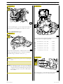
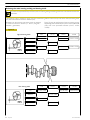
1
CURSOR TIER 3
SERIES
Industrial application
C13 TURBOCOMPOUND
Technical and Repair manual
This publication contains data, features, instructions and
methods for performing repair interventions on the assembly
and its components.
This publication is addressed to qualified, specialised personnel.
Check that you have the publication related to the assembly
on which you are about to work available before you start.
Make sure that you have all the necessary safety apparatuses,
such as, for example, protective eyewear, helmet, gloves, footwear, etc. Check that the working, lifting and transport equipment etc. is available and in working order. Make sure that the
vehicle is prepared and secured.
Proceed by carefully observing the instructions contained
herein and use the indicated specific tools to ensure correct
repair procedures, observance of time schedules and safety of
operators.
All repair interventions are aimed at restoring the conditions
of operation, efficiency and safety contemplated by FPT.
All on-vehicle interventions, aimed at implementing changes,
alterations or other not authorised by FPT will relieve FPT
from responsibility. Specifically, the warranty (where applicable) will be immediately cancelled.
FPT cannot be held responsible for repair interventions.
FPT is available to provide any additional information needed
for performing the inventions and indications in the cases and
situations not contemplated in this publication.
The data contained in this publication may not be up-to-date
if changes are made by the manufacturer at any time for technical or commercial reasons or if required to meet legal requirements of countries worldwide.
Contact a FPT dealership before proceeding in the event of differences between the contents of this publication and the
actual assembly.
Reproduction, even partial, of this text and the illustrations
contained herein is prohibited.
Produced by:
Publication edited by
FIAT Powertrain Technologies
Mkt. Advertising & Promotion
Viale dell’Industria, 15/17
20010 Pregnana Milanese
Milano (Italy)
Print P2D32C005 E - 1st Ed. 05.2006
B.U. TECHNICAL PUBLISHING
Iveco Technical Publications
Lungo Stura Lazio, 15
10156 Turin - Italy
1
F3C CURSOR ENGINES
13 CURSOR ENGINES
TURBOCOMPOUND (F3C)
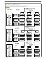
Section
Introduction
General specifications
1
Fuel
2
Industrial application
3
Overhaul and technical specifications
4
Tools
5
Safety prescriptions
Print P2D32C005 E
Appendix
Base - May 2007
2
Base - May 2007
F3C CURSOR ENGINES
Print P2D32C005 E
F3C CURSOR ENGINES
1
INTRODUCTION
Introduction
Page
Print P2D32C005 E
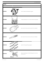
PREFACE TO USER’S GUIDELINE MANUAL . .
3
SYMBOLS
5
.............................
- Warnings . . . . . . . . . . . . . . . . . . . . . . . . . . . . .
3
- Service operations . . . . . . . . . . . . . . . . . . . . . .
3
GENERAL WARNINGS . . . . . . . . . . . . . . . . . . .
5
GENERAL WARNINGS
ON THE ELECTRIC SYSTEM . . . . . . . . . . . . .
7
- Bonding and screening . . . . . . . . . . . . . . . . . . .
8
OPTIONAL ELECTRICAL AND MECHANICAL PARTS
INSTALLATIONS . . . . . . . . . . . . . . . . . . . . . .
9
CONVERSIONS BETWEEN THE MAIN UNITS
OF MEASUREMENT OF THE INTERNATIONAL
SYSTEM AND MOST USED DERIVED
QUANTITIES . . . . . . . . . . . . . . . . . . . . . . . . .
9
KEY OF LECTURE OF THE HEADINGS
AND FOOTNOTES . . . . . . . . . . . . . . . . . . .
10
UPDATING . . . . . . . . . . . . . . . . . . . . . . . . . . . . .
11
Base - May 2007
2
INTRODUCTION
Base - May 2007
F3C CURSOR ENGINES
Print P2D32C005 E
F3C CURSOR ENGINES
INTRODUCTION
3
PREFACE TO USER’S GUIDELINE MANUAL
Manuals for repairs are split into Parts and Sections, each one of which is marked by a numeral; the contents of these sections are
indicated in the general table of contents.
The sections dealing with things mechanic introduce the specifications, tightening torque values, tool lists, assembly
detaching/reattaching operations, bench overhauling operations, diagnosis procedures and maintenance schedules.
The sections (or parts) of the electric/electronic system include the descriptions of the electric network and the assembly’s
electronic systems, wiring diagrams, electric features of components, component coding and the diagnosis procedures for the
control units peculiar to the electric system.
Section 1 describes the engines illustrating its features and working in general.
Section 2 describes the type of fuel feed.
Section 3 relates to the specific duty and is divided in four separate parts:
1. Mechanical part, related to the engine overhaul, limited to those components with different characteristics based on the relating
specific duty.
2. Electrical part, concerning wiring harness, electrical and electronic equipment with different characteristics based on the relating
specific duty.
3. Maintenance planning and specific overhaul.
4. Troubleshooting part dedicated to the operators who, being entitled to provide technical assistance, shall have simple and direct
instructions to identify the cause of the major inconveniences.
Sections 4 and 5 illustrate the overhaul operations of the engine overhaul on stand and the necessary equipment to execute such
operations.
The appendix contains a list of the general safety regulations to be respected by all installation and maintenance engineers in order
to prevent serious accidents taking place.
The manual uses proper symbols in its descriptions; the purpose of these symbols is to classify contained information. In particular,
there have been defined a set of symbols to classify warnings and a set for assistance operations.
SYMBOLS - Warnings
Danger for persons
Missing or incomplete observance of these prescriptions can cause serious danger for persons’ safety.
Danger of serious damage for the assembly
Failure to comply, both fully or in part, with such prescriptions will involve serious damage to the assembly and may
sometimes cause the warranty to become null and void.
!
General danger
It includes the dangers of above described signals.
Environment protection
Moreover, it describes the correct actions to be taken to ensure that the assembly is used in such a way so as to protect
the environment as much as possible.
NOTE
It indicates an additional explanation for a piece of information.
Service operations
Example
∅1
Ø 1 = housing for connecting rod small end bush
α
Tighten to torque
Tighten to torque + angular value
∅ 2 Ø 2 = housing for connecting rod bearings
Print P2D32C005 E
Base - May 2007
4
INTRODUCTION
Removal
Disconnection
Intake
Refitting
Connection
Exhaust
Removal
Disassembly
Operation
Fitting in place
Assembly
α
!
F3C CURSOR ENGINES
ρ
Compression ratio
Tighten to torque
Tolerance
Weight difference
Tighten to torque + angle value
Rolling torque
Press or caulk
Rotation
Regulation
Adjustment
Angle
Angular value
Warning
Note
Preload
Visual inspection
Fitting position check
Number of revolutions
Measurement
Value to find
Check
Temperature
Equipment
bar
Pressure
Surface for machining
Machine finish
Oversized
Higher than….
Maximum, peak
Interference
Strained assembly
Undersized
Less than….
Minimum
Thickness
Clearance
Selection
Classes
Oversizing
Lubrication
Damp
Grease
Temperature < 0 °C
Cold
Winter
Sealant
Adhesive
Temperature > 0 °C
Hot
Summer
Air bleeding
Base - May 2007
Print P2D32C005 E
F3C CURSOR ENGINES
INTRODUCTION
5
GENERAL WARNINGS
!
Warnings shown cannot be representative of all danger situations possibly occurring. Therefore, it is suggested to contact
immediate superiors where a danger situation occurs which is not described.
Use both specific and general-purpose toolings according to the prescriptions contained in respective use and
maintenance handbooks. Check use state and suitability of tools not subjected to regular check.
The manual handling of loads must be assessed in advance because it also depends, besides weight, on its size and on
the path.
Handling by mechanical means must be with hoisters proper as for weight as well as for shape and volume. Hoisters,
ropes and hooks used must contain clear indications on maximum carrying capacity acceptable. The use of said means
is compulsorily permitted to authorised personnel only. Stay duly clear of the load, and, anyhow, never under it.
In disassembling operations, always observe provided prescriptions; prevent mechanical parts being taken out from
accidentally striking workshop personnel.
Workshop jobs performed in pairs must always be performed in maximum safety; avoid operations which could be
dangerous for the co-operator because of lack of visibility or of his/her not correct position.
Keep personnel not authorised to operations clear of working area.
You shall get familiar with the operating and safety instructions for the assembly prior to operating on the latter. Strictly
follow all the safety indications found on the assembly.
Do not leave the running assembly unattended when making repairs.
When carrying out work on the assembly lifted off the ground, verify that the assembly is firmly placed on its supporting
stands, and that the manual/automatic safety devices have been actuated in the event that the assembly is to be lifted
by means of a hoist.
When you have to operate on assemblies powered by natural gas, follow the instructions contained in the document,
as well as all the specific safety standards provided for.
Only remove radiator cap when the engine is cold by cautiously unscrewing it in order to let system residual pressure
out.
Inflammable fuel and all inflammable fluids and liquids must be handled with care, according to what contained on harmful
materials 12-point cards. Refuelling must be performed outdoors with the engine off, avoiding lit cigarettes, free flames
or sparks in order to prevent sudden fires/bursts. Adequately store inflammable, corrosive and polluting fluids and liquids
according to what provided by regulations in force. Compulsorily avoid to use food containers to store harmful liquids.
Avoid to drill or bore pressurised containers, and throw cloths impregnated with inflammable substances into suitable
containers.
Worn out, damaged or consumable parts must be replaced by original spares.
During workshop activity, always keep the work place clean; timely clear or clean floors from accidental liquid or oil spots.
Electric sockets and electric equipment necessary to perform repair interventions must meet safety rules.
Print P2D32C005 E
Base - May 2007
6
INTRODUCTION
F3C CURSOR ENGINES
Put on, where required by the intervention, garments and protections provided in accident prevention rules; contact
with moving parts can cause serious injuries. Use suitable, preferably tight-fitted garments, and avoid to use jewels,
scarves, etc.
Do not leave the engine in motion at workshop locations not provided with a pipe to scavenge exhaust gas outside.
Avoid to breathe fumes coming from heating or from paint welding because they can cause damages to health; operate
outdoors or in suitably ventilated areas. Put on proper inspirator if paint powder is present.
Avoid contact with hot water or steam coming from the engine, radiator and pipings because they could cause serious
burns. Avoid direct contact with liquids and fluids present in vehicle systems; where an accidental contact has occurred,
refer to 12-point cards for provisions to make.
Clean the assemblies and carefully verify that they are intact prior to overhauling. Tidy up detached or disassembled
parts with their securing elements (screws, nuts, etc.) into special containers.
Check for the integrity of the parts which prevent screws from being unscrewed: broken washers, dowels, clips, etc.
Self-locking nuts with an insert made of nylon must always be replaced.
Avoid contact of rubber parts with diesel oil, petrol or other not compatible substances.
Before washing under pressure mechanical parts, protect electric connectors, and central units, if present.
Tightening screws and nuts must always be according to prescriptions; IVECO Motors commercial and assistance
network is available to give all clarifications necessary to perform repair interventions not provided in this document.
Before welding:
- Disconnect all electronic central units, take power cable off battery positive terminal (connect it to chassis bonding)
and detach connectors.
- Remove paint by using proper solvents or paint removers and clean relevant surfices with soap and water.
- Await about 15 minutes before welding.
- Equip with suitable fire resistant protections to protect hoses or other components where fluids or other materials
flow which may catch fire easily on welding.
Should the vehicle be subjected to temperatures exceeding 80°C (dryer ovens), disassemble drive electronic central
units.
The disposal of all liquids and fluids must be performed with full observance of specific rules in force.
Base - May 2007
Print P2D32C005 E
F3C CURSOR ENGINES
INTRODUCTION
7
GENERAL WARNINGS ON THE ELECTRIC SYSTEM
!
If an intervention has to be made on the electric/electronic system, disconnect batteries from the system; in this case,
always disconnect, as a first one, the chassis bonding cable from batteries negative terminal.
Before connecting the batteries to the system, make sure that the system is well isolated.
Disconnect the external recharging apparatus from the public utility network before taking apparatus pins off battery
terminals.
Do not cause sparks to be generated in checking if the circuit is energised.
Do not use a test lamp in checking circuit continuity, but only use proper control apparatuses.
Make sure that the electronic devices wiring harnesses (length, lead type, location, strapping, connection to screening
braiding, bonding, etc.) comply with IVECO Motors system and are carefully recovered after repair or maintenance
interventions.
Measurements in drive electronic central units, plugged connections and electric connections to components can only
be made on proper testing lines with special plugs and plug bushes. Never use improper means like wires, screwdrivers,
clips and the like in order to avoid the danger of causing a short circuit, as well as of damaging plugged connections, which
would later cause contact problems.
To start up the engine, do not use fast chargers. Start up must only be performed with either separate batteries or special
truck.
A wrong polarisation of supply voltage in drive electronic central units (for instance, a wrong polarisation of batteries)
can cause them to be destroyed.
Disconnect the batteries from the system during their recharging with an external apparatus.
On connecting, only screw up connector (temperature sensors, pressure sensors etc.) nuts at prescribed tightening
torque.
Before disconnecting the junction connector from an electronic central unit, isolate the system.
Do not directly supply electronic central units servo components at nominal vehicle voltage.
Cables must be arranged such as to result to be parallel to reference plane, i.e. as close as possible to chassis/body
structure.
Once the intervention on the electric system has been completed, recover connectors and wiring harnesses according
to original arrangement.
NOTE
Connectors present must be seen from cable side. Connectors views contained in the manual are representative of cable
side.
Print P2D32C005 E
Base - May 2007
8
INTRODUCTION
F3C CURSOR ENGINES
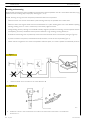
Bonding and screening
Negative leads connected to a system bonded point must be both as short and possible and “star“-connected to each other, trying
then to have their centering tidily and properly made (Figure 1, re. M).
Further, following warnings are to be compulsorily observed for electronic components:
-
Electronic central units must be connected to system bonding when they are provided with a metallic shell.
-
Electronic central units negative cables must be connected both to a system bonding point such as the dashboard opening
bonding (avoiding “serial“ or “chain“ connections), and to battery negative terminal.
-
Analog bonding (sensors), although not connected to battery negative system/terminal bonding, must have optimal isolation.
Consequently, particularly considered must be parasitic resistances in lugs: oxidising, clinching defects, etc.
-
Screened circuits braiding must only electrically contact the end towards the central unit entered by the signal (Figure 2).
-
If junction connectors are present, unscreened section d, near them, must be as short as possible (Figure 2).
-
Cables must be arranged such as to result to be parallel to reference plane, i.e. as close as possible to chassis/body structure.
Figure 1
1.
NEGATIVE CABLES “STAR“ CONNECTION TO SYSTEM BONDING M
Figure 2
88039
2.
SCREENING THROUGH METALLIC BRAIDING OF A CABLE TO AN ELECTRONIC COMPONENT — C. CONNECTOR
d. DISTANCE ! 0
Base - May 2007
Print P2D32C005 E
F3C CURSOR ENGINES
INTRODUCTION
9
OPTIONAL ELECTRICAL AND MECHANICAL PARTS INSTALLATIONS
Assemblies shall be modified and equipped with additions - and their accessories shall be fitted - in accordance with the assembling
directives issued.
It is reminded that, especially about the electric system, several electric sockets are provided for as series (or optional) sockets in
order to simplify and normalise the electrical intervention that is care of preparation personnel.
It is absolutely forbidden to make modifications or connections to electric central units wiring harnesses; in particular,
the data interconnection line between central units (CAN line) is to be considered inviolable.
CONVERSIONS BETWEEN THE MAIN UNITS OF MEASUREMENT
INTERNATIONAL SYSTEM AND MOST USED DERIVED QUANTITIES
Power
1 kW
1 kW
1 metric HP
1 metric HP
1 HP
1 HP
=
=
=
=
=
=
1.36 metric HP
1.34 HP
0.736 kW
0.986 HP
0.746 kW
1.014 metric HP
Torque
1 Nm
1 kgm
=
=
0.1019 kgm
9.81 Nm
OF
THE
Revolutions per time unit
1 rad/s
= 1 rpm x 0.1046
1 rpm
= 1 rad/s x 9.5602
Pressure
1 bar
1 kg/cm2
1 bar
=
=
=
1.02 kg/cm2
0.981 bar
105 Pa
Where accuracy is not particularly needed:
- Nm unit is for the sake of simplicity converted into kgm according to ratio 10:1
1 kgm
=
10 Nm;
- bar unit is for the sake of simplicity converted into kg/cm2 according to ratio 1:1
1 kg/cm2
=
1 bar.
Temperature
0° C = 32° F
1° C = (1 x 1.8 + 32) ° F
Print P2D32C005 E
Base - May 2007
10
INTRODUCTION
F3C CURSOR ENGINES
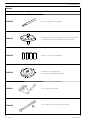
KEY OF LECTURE OF THE HEADINGS AND FOOTNOTES
Type of
vehicle
Printout
number
Base - May 2007
Section
title
Language
Publication
Basic edition referred to
month - year editorial
phase closing
Page
number
When month - year update
is present (revi) to the
basic edition
Print P2D32C005 E
F3C CURSOR ENGINES
INTRODUCTION
11
UPDATING
Section
Print P2D32C005 E
Description
Page
Date of revision
Base - May 2007
12
INTRODUCTION
Base - May 2007
F3C CURSOR ENGINES
Print P2D32C005 E
F3C CURSOR ENGINES
1
SECTION 1 - GENERAL SPECIFICATIONS
SECTION 1
General specifications
Page
Print P2D32C005 E
CORRESPONDENCE BETWEEN TECHNICAL CODE
AND COMMERCIAL CODE . . . . . . . . . . . . .
3
VIEWS OF ENGINE F3CE0684A*E001 . . . . . . .
5
VIEWS OF ENGINE F3CE0684B*E003 . . . . . . . .
8
LUBRICATION DIAGRAM . . . . . . . . . . . . . . . . .
11
- Engine F3CE0684A*E001 . . . . . . . . . . . . . . . .
11
- Engine F3CE0684B*E003 . . . . . . . . . . . . . . . .
12
- Oil pump . . . . . . . . . . . . . . . . . . . . . . . . . . . . .
13
- Overpressure valve . . . . . . . . . . . . . . . . . . . . .
13
- Oil pressure control valve . . . . . . . . . . . . . . . .
14
- Heat exchanger . . . . . . . . . . . . . . . . . . . . . . . .
14
- By-pass valve . . . . . . . . . . . . . . . . . . . . . . . . . .
15
- Thermostatic valve . . . . . . . . . . . . . . . . . . . . . .
15
- Engine oil filters . . . . . . . . . . . . . . . . . . . . . . . .
15
COOLING . . . . . . . . . . . . . . . . . . . . . . . . . . . . .
16
- Water pump . . . . . . . . . . . . . . . . . . . . . . . . . .
17
- Thermostat . . . . . . . . . . . . . . . . . . . . . . . . . . .
17
TURBOCHARGING . . . . . . . . . . . . . . . . . . . . . .
18
TURBOCOMPOUND SYSTEM . . . . . . . . . . . . .
19
Base - May 2007
2
SECTION 1 - GENERAL SPECIFICATIONS
Base - May 2007
F3C CURSOR ENGINES
Print P2D32C005 E
F3C CURSOR ENGINES
SECTION 1 - GENERAL SPECIFICATIONS
3
CORRESPONDENCE BETWEEN TECHNICAL CODE AND COMMERCIAL CODE
Print P2D32C005 E
Technical Code
Commercial Code
F3CE0684A*E001
F3CE0684B*E003
-
Base - May 2007
4
SECTION 1 - GENERAL SPECIFICATIONS
Base - May 2007
F3C CURSOR ENGINES
Print P2D32C005 E
F3C CURSOR ENGINES
SECTION 1 - GENERAL SPECIFICATIONS
5
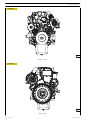
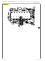
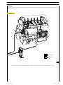
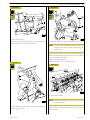
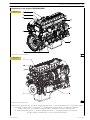
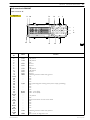
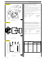
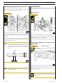
VIEWS OF ENGINE F3CE0684A*E001
Figure 1
110587
LEFT-HAND SIDE VIEW
Figure 2
110588
RIGHT-HAND SIDE VIEW
Print P2D32C005 E
Base - May 2007
6
SECTION 1 - GENERAL SPECIFICATIONS
F3C CURSOR ENGINES
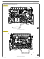
Figure 3
110589
FRONT VIEW
Figure 4
110590
REAR VIEW
Base - May 2007
Print P2D32C005 E
F3C CURSOR ENGINES
SECTION 1 - GENERAL SPECIFICATIONS
7
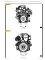
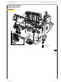
Figure 5
110591
TOP VIEW
Print P2D32C005 E
Base - May 2007
8
SECTION 1 - GENERAL SPECIFICATIONS
F3C CURSOR ENGINES
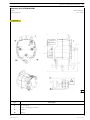
VIEWS OF ENGINE F3CE0684B*E003
Figure 6
110594
LEFT-HAND SIDE VIEW
Figure 7
110595
RIGHT-HAND SIDE VIEW
Base - May 2007
Print P2D32C005 E
F3C CURSOR ENGINES
SECTION 1 - GENERAL SPECIFICATIONS
9
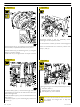
Figure 8
110596
FRONT VIEW
Figure 9
110598
REAR VIEW
Print P2D32C005 E
Base - May 2007
10
SECTION 1 - GENERAL SPECIFICATIONS
F3C CURSOR ENGINES
Figure 10
110597
TOP VIEW
Base - May 2007
Print P2D32C005 E
F3C CURSOR ENGINES
SECTION 1 - GENERAL SPECIFICATIONS
11
LUBRICATION DIAGRAM
F3CE0684A*E001 Engine
Figure 11
Dropping oil
Pressure oil
110604
Print P2D32C005 E
Base - May 2007
12
SECTION 1 - GENERAL SPECIFICATIONS
F3C CURSOR ENGINES
F3CE0684B*E003 Engine
Figure 12
Dropping oil
Pressure oil
110599
Base - May 2007
Print P2D32C005 E
F3C CURSOR ENGINES
SECTION 1 - GENERAL SPECIFICATIONS
13
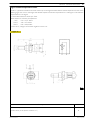
Overpressure valve
Oil pump
Figure 13
Figure 15
60560
73540
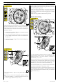
The oil pump (1) cannot be overhauled. On finding any
damage, replace the oil pump assembly.
MAIN DATA TO CHECK THE OVERPRESSURE
VALVE SPRING
See under the relevant heading for replacing the gear (2) of
the crankshaft.
Figure 14
1
73541
OIL PUMP CROSS-SECTION
1. Overpressure valve — Start of opening pressure 10 ± 1 bars.
Print P2D32C005 E
Base - May 2007
14
SECTION 1 - GENERAL SPECIFICATIONS
F3C CURSOR ENGINES
Oil pressure control valve
Figure 17
Figure 16
73542
The oil pressure control valve is located on the left-hand side
of the crankcase.
Start of opening pressure 5 bars.
73543
MAIN DATA TO CHECK THE OIL PRESSURE
CONTROL VALVE SPRING
Heat exchanger
Figure 18
104236
HEAT EXCHANGER
The heat exchanger is fitted with: 1. Oil pressure/temperature sensor - 2. By-pass valve - 3. Heat valve.
Base - May 2007
Print P2D32C005 E
F3C CURSOR ENGINES
SECTION 1 - GENERAL SPECIFICATIONS
15
This is a new generation of filters that permit much more
thorough filtration as they are able to holder back a greater
amount of particles of smaller dimensions than those held
back by conventional filters with a paper filtering element.
By-pass valve
Figure 19
These high-filtration devices, to date used only in industrial
processes, make it possible to:
- reduce the wear of engine components over time;
- maintain the performance/specifications of the oil and
thereby lengthen the time intervals between changes.
73545
The valve quickly opens at a pressure of: 3 bars.
Thermostatic valve
Figure 20
External spiral winding
The filtering elements are closely wound by a spiral so that
each fold is firmly anchored to the spiral with respect to the
others. This produces a uniform use of the element even in
the worst conditions such as cold starting with fluids with a
high viscosity and peaks of flow. In addition, it ensures uniform distribution of the flow over the entire length of the
filtering element, with consequent optimization of the loss of
load and of its working life.
Mount upstream
To optimize flow distribution and the rigidity of the filtering element, this has an exclusive mount composed of a strong mesh
made of nylon and an extremely strong synthetic material.
73546
Start of opening:
- travel 0.1 mm at a temperature of 82 ±2°C.
End of opening:
- travel 8 mm at a temperature of 97°C.
Filtering element
Composed of inert inorganic fibres bound with an exclusive
resin to a structure with graded holes, the element is manufactured exclusively to precise procedures and strict quality
control.
Mount downstream
A mount for the filtering element and a strong nylon mesh
make it even stronger, which is especially helpful during cold
starts and long periods of use. The performance of the filter
remains constant and reliable throughout its working life and
from one element to another, irrespective of the changes in
working conditions.
Engine oil filters
Figure 21
Structural parts
The o-rings equipping the filtering element ensure a perfect
seal between it and the container, eliminating by-pass risks
and keeping filter performance constant. Strong corrosionproof bottoms and a sturdy internal metal core complete the
structure of the filtering element.
When mounting the filters, keep to the following rules:
- Oil and fit new seals.
- Screw down the filters to bring the seals into contact
with the supporting bases.
- Tighten the filter to a torque of 35-40 Nm.
47447
Print P2D32C005 E
Base - May 2007
16
SECTION 1 - GENERAL SPECIFICATIONS
F3C CURSOR ENGINES
COOLING
Figure 22
Water flowing out of the thermostat
Water circulating in the engine
Water flowing into the pump
104278
ILLUSTRATIVE DIAGRAM
Base - May 2007
Print P2D32C005 E
F3C CURSOR ENGINES
SECTION 1 - GENERAL SPECIFICATIONS
Water pump
17
Figure 25
Figure 23
TO THE
RADIATOR
TO THE
EXPANSION
TUB
FROM
THE ENGINE
TO THE
BY PASS
60748
104239
Water leaving the thermostat
Check the thermostat works properly; replace it if in doubt.
CROSS-SECTION OF THE WATER PUMP
The water pump comprises: rotor, shaft with bearing.
T-gasket and drive pulley.
Temperature of start of travel 84°C ±2°C.
Minimum travel 15 mm at 94°C ±2°C.
Check that the pump body has no cracks or water
leakage; if it does, replace the entire water pump.
Thermostat
View of thermostat operation
Figure 24
TO THE
RADIATOR
TO THE
EXPANSION
TUB
FROM
THE ENGINE
TO THE
BY PASS
60747
Water circulating in the engine
Print P2D32C005 E
Base - May 2007
18
SECTION 1 - GENERAL SPECIFICATIONS
F3C CURSOR ENGINES
TURBOCHARGER
The turbocharger increases the air flow rate during the suction stroke of the combustion cycle. The contribution of extra air
improves combustion and increases engine efficiency.
The exhaust gases are conveyed towards the turbocharger turbine where they give part of their energy and turn the turbine
itself. During this step, the exhaust gas temperature drops to approximately 600˚C.
A centrifuge compressor is mounted coaxially to the turbine with the task of aspirating and comprising the previous cleaned
air from the external environment.
During compression, the air temperature increases and is thus cooled by a heat exchanger (intercooler) before being conveyed
to the intake manifold.
Figure 26
Exhaust gas
Intake air
Compressed hot air
Compressed intake air
119991
Base - May 2007
Print P2D32C005 E
F3C CURSOR ENGINES
SECTION 1 - GENERAL SPECIFICATIONS
19
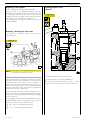
TURBOCOMPOUND SYSTEM
In a turbocompound system, a second ”power” turbine is mounted in series to the normal engine turbocharger and coupled
to a Voith hydraulic coupling.
The ”power” turbine, via a gear set, transmits energy to the crankshaft obtaining a power increase of approximately 8% without
increasing fuel consumption.
The Voith hydraulic coupling uses engine oil and is required balance and adjust the engine rate variation between power turbine
and crankshaft.
The exhaust gases produced by the combustion are conveyed to the turbocharger turbine; here, they expand and give part of
their energy by operating the turbocharger and compressing the engine intake air: this increases both engine power and torque.
At first turbo outlet, the exhaust gases reach a temperature of approximately 600˚C.
At this point, the exhaust gases are directed to the second ”power” turbine which is capable of reaching a revolution speed of
approximately 52.000 rpm at the maximum output power (70 kW).
Also in this case, the exhaust gases give part of their energy and by expanding their temperature drops to about 500˚C. After
the power turbine, the exhaust gases return to the normal exhaust system.
In addition to further abating the temperature of the exhaust gases, this system allows to contain emissions to level Tier 3, without
using other technologies.
Figure 27
Engine intake air
Exhaust gas
110601
TURBOCOMPOUND PRINCIPLE DIAGRAM
1. Turbocharger - 2. Lubrication delivery to Voith coupling - 3 Voith hydraulic coupling - 4. Lubrication return circuit from
Voith coupling - 5. Motion output gear from Voith coupling - 6. Power turbine.
Print P2D32C005 E
Base - May 2007
20
SECTION 1 - GENERAL SPECIFICATIONS
F3C CURSOR ENGINES
Figure 28
TCD turbocharger rate (krpm)
TCD turbocharger power (kW)
Engine rate (rpm)
110602
The graph shows the power curve pattern and ”power” turbine rate according to engine rpm.
Base - May 2007
Print P2D32C005 E
F3C CURSOR ENGINES
SECTION 2 - FUEL
1
SECTION 2
Fuel
Page
Print P2D32C005 E
FEEDING . . . . . . . . . . . . . . . . . . . . . . . . . . . . . . .
3
FUEL SUPPLY DIAGRAM . . . . . . . . . . . . . . . . . .
4
- Injector-pump . . . . . . . . . . . . . . . . . . . . . . . . .
5
- Fuel pump . . . . . . . . . . . . . . . . . . . . . . . . . . . .
5
Base - May 2007
2
SECTION 2 - FUEL
Base - May 2007
F3C CURSOR ENGINES
Print P2D32C005 E
F3C CURSOR ENGINES
SECTION 2 - FUEL
3
FEEDING
Fuel is supplied via a fuel pump, filter and pre-filter, 6 pump-injectors governed by the camshaft via rocker arms and by the
electronic control unit.
Figure 1
Return circuit
Supply circuit
104280
1. Valve for return circuit, starts opening at 3.5 bars - 2. Valve for return circuit, starts opening at 0.2 bars.
Print P2D32C005 E
Base - May 2007
4
SECTION 2 - FUEL
F3C CURSOR ENGINES
FUEL SUPPLY DIAGRAM
Figure 2
104242
1. Temperature sensor - 2. Bleed valve - 3. Secondary fuel filter - 4. By-pass valve (0.3 ÷ 0.4 bar) - 5. Fuel supply pump 6. Integrated valve (3.5 bar) - 7. Pressure relief valve (5 bar) - 8. Fuel tank - 9. Priming pump - 10. Primary fuel filter 11. Check valve (opening 0.1 bar) - 12. Heater - 13. Electronic control unit - 14. Fuel return union with valve built in
(0.2 bar) - 15. Pump-injectors.
Base - May 2007
Print P2D32C005 E
F3C CURSOR ENGINES
SECTION 2 - FUEL
5
Pumping element
The pumping element is operated by a rocker arm governed
directly by the cam of the camshaft.
The pumping element is able to ensure a high delivery
pressure. The return stroke is made by means of a return
spring.
Fuel pump
Figure 3
73547
A. Fuel inlet — B. Fuel delivery — C. By-pass nut —
D. Fuel return from the pump-injectors —
E. Pressure relief valve — Opening pressure: 5 - 5.8 bars.
Figure 4
73548
CROSS-SECTION OF THE FUEL PUMP
1. Oil and fuel leakage indicator.
Injector-pump
Nozzle
Garages are authorized to perform fault diagnosis solely on
the entire injection system and may not work inside the
injector-pump, which must only be replaced.
A specific fault-diagnosis program, included in the control
unit, is able to check the operation of each injector (it
deactivates one at a time and checks the delivery of the other
five).
Fault diagnosis makes it possible to distinguish errors of an
electrical origin from ones of a mechanical/hydraulic origin.
It indicates broken pump-injectors.
It is therefore necessary to interpret all the control unit error
messages correctly.
Any defects in the injectors are to be resolved by replacing
them.
Solenoid valve
The solenoid, which is energized at each active phase of the
cycle, via a signal from the control unit, controls a slide valve
that shuts off the pumping element delivery pipe.
When the solenoid is not energized, the valve is open, the
fuel is pumped but it flows back into the return pipe with the
normal transfer pressure of approximately 5 bars.
When the solenoid is energized, the valve shuts and the fuel,
not being able to flow back into the return pipe, is pumped
into the nozzle at high pressure, causing the needle to lift.
The amount of fuel injected depends on the length of time
the slide valve is closed and therefore on the time for which
the solenoid is energized.
The solenoid valve is joined to the injector body and cannot
be removed.
On the top there are two screws securing the electrical
wiring from the control unit.
To ensure signal transmission, tighten the screws with a torque
wrench to a torque of 1.36 — 1.92 Nm (0.136 — 0.192 kgm).
Figure 5
104243
1. Fuel/oil seal — 2. Fuel/diesel seal — 3. Fuel/exhaust gas seal.
The injector-pump is composed of: pumping element, nozzle,
solenoid valve.
Print P2D32C005 E
Base - May 2007
6
SECTION 2 - FUEL
F3C CURSOR ENGINES
Figure 6
104245
For each injector replaced, hook up to the diagnostic station
and, when asked by the program, enter the code punched on
the injector (→) to reprogram the control unit.
Base - May 2007
Print P2D32C005 E
F3C CURSOR ENGINES
SECTION 3 - INDUSTRIAL APPLICATION
1
SECTION 3
Industrial application
Page
Print P2D32C005 E
CLEARANCE DATA . . . . . . . . . . . . . . . . . . . . .
3
PART ONE MECHANICAL COMPONENTS . . . . . . . . .
5
ENGINE OVERHAUL PROCEDURE . . . . . . . .
7
- Disassembling . . . . . . . . . . . . . . . . . . . . . . . . .
7
- Assembly . . . . . . . . . . . . . . . . . . . . . . . . . . . . .
15
ENGINE FLYWHEEL . . . . . . . . . . . . . . . . . . . . .
19
- Fitting engine flywheel
(For engine F3CE0684B*E003) . . . . . . . . . . . .
19
- Fitting engine flywheel
(For engine F3CE0684A*E001) . . . . . . . . . . .
19
- Fitting camshaft . . . . . . . . . . . . . . . . . . . . . . . .
20
- Fitting pump-injectors . . . . . . . . . . . . . . . . . . .
21
- Fitting rocker-arm shaft assembly . . . . . . . . . .
21
- Camshaft timing . . . . . . . . . . . . . . . . . . . . . . .
22
- Phonic wheel timing . . . . . . . . . . . . . . . . . . . .
24
- Intake and exhaust rocker play adjustment and
pre-loading of rockers controlling pump injectors
25
ENGINE COMPLETION . . . . . . . . . . . . . . . . . .
27
PART TWO ELECTRICAL EQUIPMENT . . . . . . . . . . . . .
35
- Components on the engine . . . . . . . . . . . . . .
37
- Components on the engine . . . . . . . . . . . . . .
38
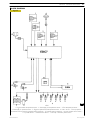
BLOCK DIAGRAM . . . . . . . . . . . . . . . . . . . . . . .
39
- EDC 7 UC31 electronic control unit . . . . . . .
40
- EDC control unit PIN-OUT . . . . . . . . . . . . . .
41
Base - May 2007
2
SECTION 3 - INDUSTRIAL APPLICATION
F3C CURSOR ENGINES
Page
INJECTOR PUMP . . . . . . . . . . . . . . . . . . . . . . . .
44
- Engine coolant temperature sensor . . . . . . . . .
45
- Fuel temperature sensor . . . . . . . . . . . . . . . . .
46
- Flywheel pulse transmitter . . . . . . . . . . . . . . . .
47
- Distribution pulse transmitter . . . . . . . . . . . . .
48
- Alternator (For F3CE0684B*E003) . . . . . . . . .
49
- Alternator (For F3CE0684A*E001) . . . . . . . . .
50
- Starting motor . . . . . . . . . . . . . . . . . . . . . . . . .
52
PRE/POST-HEATING RESISTANCE . . . . . . . . . .
53
EDC SYSTEM FUNCTIONS . . . . . . . . . . . . . . . .
54
PART THREE TROUBLESHOOTING . . . . . . . . . . . . . . . . .
57
PREFACE . . . . . . . . . . . . . . . . . . . . . . . . . . . . . . .
59
FAULT CODE . . . . . . . . . . . . . . . . . . . . . . . . . . .
60
Base - May 2007
Print P2D32C005 E
F3C CURSOR ENGINES
SECTION 3 - INDUSTRIAL APPLICATION
3
CLEARANCE DATA
Type
ρ
F3CE0684A*E001
16.5 ± 0.8
Compression ratio
Max. output
Max. torque
kW
(HP)
rpm
425
(578)
402
(547)
1800
1800
Nm
(kgm)
rpm
2450
(245)
1500
2442
(244)
1400
rpm
600
875
rpm
mm
cm3
2110
2350
Loadless
engine
idling
Loadless
engine
peak
Bore x stroke
Displacement
135 x 150
12880
SUPERCHARGING
Intercooler
Direct injection
Turbocharger type
HOLSET HE551
Forced by gear pump, relief valve single action
oil filter
LUBRICATION
bar
F3CE0684B*E003
Oil pressure
(warm engine)
- idling
- peak rpm
bar
bar
COOLING
Water pump control
Thermostat
- start of opening
ºC
3
4.5
Liquid
Through belt
81
NOTE Data, features and performances are valid only if the setter fully complies with all the installation prescriptions provided
by Iveco Motors.
Furthermore, the users assembled by the setter shall always be in conformance to couple, power and number of turns
based on which the engine has been designed.
Print P2D32C005 E
Base - May 2007
4
SECTION 3 - INDUSTRIAL APPLICATION
Base - May 2007
F3C CURSOR ENGINES
Print P2D32C005 E
F3C CURSOR ENGINES
SECTION 3 - INDUSTRIAL APPLICATION
5
PART ONE MECHANICAL COMPONENTS
Print P2D32C005 E
Base - May 2007
6
SECTION 3 - INDUSTRIAL APPLICATION
Base - May 2007
F3C CURSOR ENGINES
Print P2D32C005 E
F3C CURSOR ENGINES
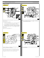
7
SECTION 3 - INDUSTRIAL APPLICATION
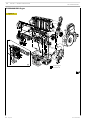
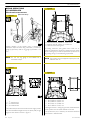
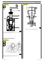
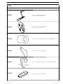
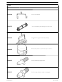
ENGINE OVERHAUL PROCEDURE
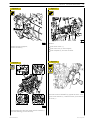
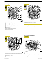
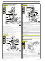
Disassembling
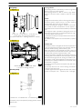
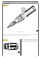
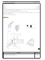
Figure 9
Handle all parts with great care. Never put your
hands or fingers between one part and another.
Wear suitable personal protective equipment such
as a visor, gloves and safety shoes.
Cover all electrical components before washing with
high-pressure water jets.
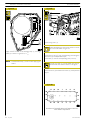
Figure 7
104781
Loosen the locking screws and remove the compressor (1)
complete with its support (2) from the engine.
Loosen the locking screws and remove the alternator (3).
Loosen the locking screws and remove the alternator support
(4) from the engine.
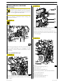
Figure 10
119479
Before securing the engine to the rotary stand, remove: the
electrical cable of the engine (2) by unplugging it from the
control unit (1) and from all sensors transmitters to which it
is connected.
Only for F3CE0684B*E003 engine
Figure 8
Remove:
104780
Using an appropriate tool, regulate the belt tightener (2) to
release the pressure and remove the belt (1) for controlling
various parts.
Print P2D32C005 E
-
104782
the fixed belt tightening roller (1);
the support (2);
the automatic belt tightener (3);
the damping flywheel (4) and the pulley beneath it;
all the coolant pipes (5);
the water pump (6);
the fixed belt tightening roller (7);
the thermostat assembly (8).
Base - May 2007
8
SECTION 3 - INDUSTRIAL APPLICATION
F3C CURSOR ENGINES
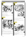
Only for F3CE0684A*E001 engine
Figure 13
Figure 11
104251
104249
Using a suitable tool (3), work in the direction of the arrow on
the tightener (2) and remove the belt (1).
Remove:
-
thermostat assembly (8);
pipes complete with coolant (6);
pulley (4);
water pump (7);
automatic tightener support (1);
fixed tightener (5);
damper flywheel (3) and pulley beneath;
automatic tightener (2);
Figure 14
Figure 12
119487
119478
Loosen and remove the screws (3) and (4) fastening the
alternator (1) to the supporting brackets (2) and (5).
Remove the supporting brackets (2) and (5) from the
crankcase.
Base - May 2007
Remove the oil pressure adjustment valve (1).
Loosen and remove the screw (2) fastening the hydraulic
coupling to the flywheel casing.
Print P2D32C005 E
F3C CURSOR ENGINES
SECTION 3 - INDUSTRIAL APPLICATION
Figure 15
9
Figure 17
119480
104247
Remove:
- the starter motor (1);
- the control unit (2) and its support;
- the oil dipstick (3) from the crankcase.
Remove the engine supports;
Remove the drive (1).
Figure 18
Figure 16
99361
With the extractor 99340053 (2) applied as shown in the
figure, extract the seal (4). Undo the screws (3) and take off
the cover (1).
104248
Secure the engine to the rotary stand with the brackets (1).
Drain the lubricating oil from the sump.
Print P2D32C005 E
Base - May 2007
10
SECTION 3 - INDUSTRIAL APPLICATION
F3C CURSOR ENGINES
Figure 19
Figure 21
119481
On exhaust side of the engine:
- loosen the clamps (1 and 2);
- remove the connection manifold
turbocharger and power turbine.
(3)
between
119484
Figure 20
In order to remove the turbocharger (2):
- remove the screws (1) and recover the shims (3);
- remove the two nuts (5);
Recover the seal (4) after removing the turbocharger (2)
Figure 22
119483
In order to remove the oil delivery pipe (1) from the
turbocharger:
- loosen the fitting (2) on the oil filter assembly;
- loosen and remove the turbocharger fastening screws (6).
Remove the oil return tube (4) from the turbocharger:
- - loosen the screws (3 and 5) fastening the pipe to the
crankcase and to the turbocharger itself.
Base - May 2007
119485
Loosen and remove the screws (1) fastening the exhaust
manifold (3) to the crankcase.
Remove the shims (2).
Detach the exhaust manifold (2) from the crankcase and
recover the seals.
Print P2D32C005 E
F3C CURSOR ENGINES
SECTION 3 - INDUSTRIAL APPLICATION
Figure 23
11
Figure 25
119489
Loosen and remove the screws (1) fastening the oil return
pipe (2) to the hydraulic coupling.
119486
Loosen and remove the screws (1) fastening the power
turbine (2) to the hydraulic coupling.
Figure 26
Detach the power turbine (2) from the hydraulic
coupling.
Figure 24
119490
Loosen and remove the screws (1) fastening the hydraulic
coupling (2) to the flywheel casing.
Detach the hydraulic coupling (2) from the flywheel casing.
119488
Loosen the unions (1 and 2) and remove the oil delivery pipe
from the hydraulic coupling.
Print P2D32C005 E
Base - May 2007
12
SECTION 3 - INDUSTRIAL APPLICATION
F3C CURSOR ENGINES
Figure 27
Figure 29
104783
Loosen the screws (1) and remove the intake manifold (2)
from the engine.
119491
Remove the plate (1) and remove traces of sealant from the
part in contact with the flywheel casing.
NOTE The air intake joint (3) may have different positions
depending on the type of engine.
Figure 30
Figure 28
60496
-
Unscrew the screws (2) and remove the gear (1) fitted
with phonic wheel.
Figure 31
85480
Remove the rocker arm cover (1), take off the screws (2) and
remove: the cover (3), the filter (5) and the gaskets (4 and 6).
Take off the screws (8) and remove the blow-by case (7).
60497
-
Base - May 2007
Unscrew the screws (1); tighten one screw in a reaction
hole and remove the shoulder plate (2), remove the sheet
gasket.
Print P2D32C005 E
F3C CURSOR ENGINES
13
SECTION 3 - INDUSTRIAL APPLICATION
Figure 32
Figure 35
60498
60501
Unscrew the screws (2) and remove the transmission gear (1).
Unscrew the screws (1) and take down the gearbox (2).
Figure 36
Figure 33
119492
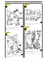
In sequence, take out the:
60499
Stop the engine flywheel (3) rotation by means of tool
99360351 (1), unscrew the fixing screws (2) and remove the
engine flywheel (3).
- idle gear (1);
- oil pump gear (2)
- transmission gear (3);.
Figure 37
Figure 34
119493
60500
Apply the extractor 99340054 (2) and pull out the seal
gasket (1).
Print P2D32C005 E
Loosen and remove the screws (1).
Remove the intermediate gear support shaft. .
Base - May 2007
14
SECTION 3 - INDUSTRIAL APPLICATION
F3C CURSOR ENGINES
Figure 38
Figure 41
60514
104257
- Disconnect the electrical connections from the pump
injectors.
- Unscrew the screws (1) fixing the rocker arm shaft.
- Fit the plugs 99360180 (1) instead of injectors.
- Remove the camshaft (2).
- Unscrew the fixing screws on the cylinder head (3).
Figure 39
Figure 42
116814
Apply tool 99360553 (1) to the rocker holder shaft (5) and
remove the shaft (5) from the cylinder head.
60515
- By means of metal ropes, lift the cylinder head (1).
Figure 40
- Remove the seal (2)
Only for F3BC0684A*E001 engine
Figure 43
102935
To extract the pump injector from the engine block, using the
tool proceed as follows:
- Hook up the detail (3) of the tool illustrated in the figure
to the injector pump (4);
- fit part (2) on part (3), resting the former on the cylinder
head;
- tighten the nut (1) and extract the pump injector (4) from
the engine block
Base - May 2007
101606
Loosen screws (3), then remove sump (1) complete with
spacer (2) and seal gasket (4).
Print P2D32C005 E
F3C CURSOR ENGINES
SECTION 3 - INDUSTRIAL APPLICATION
Only for F3BC0684A*E001 engine
Figure 44
15
Engine assembly
Figure 46
60563
104784
Using the centring ring 99396035 (2), check the exact position
of the cover (1). If it is wrong, proceed accordingly and lock
the screws (3).
Figure 47
Loosen screws (3), then remove sump (1) complete with
spacer (2) and seal gasket (4).
Figure 45
60564
Key on the gasket (1), mount the key 99346250 (2) and,
screwing down the nut (3), drive in the gasket (1).
Figure 48
101607
Loosen the screws, then remove suction strainer (1).
60515
Check that the pistons 1-6 are exactly at the T.D.C.
Put the gasket (2) on the crankcase.
Mount the cylinder head (1) and tighten the screws as shown
in Figs. 43 - 44 - 45.
!
Print P2D32C005 E
Lubricate the thread of the screws with engine oil
before assembly.
Base - May 2007
16
SECTION 3 - INDUSTRIAL APPLICATION
F3C CURSOR ENGINES
Figure 49
Figure 52
α
61270
Diagram of the tightening sequence of the screws fixing the
cylinder head.
60567
Mount the oil pump (4), the intermediate gears (2) together
with the link rod (1) and lock the screws (3) in two phases:
- pre-tightening 30 Nm.
- closing to angle 90°.
Figure 50
Figure 53
60565
- Pre-tightening with the torque wrench (1):
1st phase: 60 Nm (6 kgm).
2nd phase: 120 Nm (12 kgm).
119495
Replace the o-ring (1) if the support shaft of the intermediate
gear was removed.
Figure 51
Figure 54
α
60566
- Closing to angle with tool 99395216 (1):
3rd phase: angle of 120°.
4th phase: angle of 60°.
Base - May 2007
119493
Fit the support shaft (2) of the intermediate gear in its seat.
Fasten the fastening screws (1) and tighten at a torque of 115
Nm.
Print P2D32C005 E
F3C CURSOR ENGINES
SECTION 3 - INDUSTRIAL APPLICATION
Figure 55
17
Figure 57
119496
Fit the intermediate gear (1) on the support shaft. Fasten the
fastening screws (2) and tighten at a torque of 115 Nm.
Only for F3BC0684B*E003 engine
Figure 56
119497
Using a torque wrench, tighten the highlighted screws with the
following sequence and tightening torques:
104311
:
8 screws M12 x 1.75 x 100
63 Nm
2 screws M12 x 1.75 x 160
63 Nm
6 screws M12 x 1.75 x 35
63 Nm
2 screws M12 x 1.75 x 120
63 Nm
1 screw M12 x 1.75 x 130
63 Nm
Apply LOCTITE 5970 IVECO n˚ 2992644 silicone on the gear
housing, using appropriate tools (1), as shown in the figure.
The sealer string (1) diameter is to be 1,5 ± 0.5
0.2
Figure 58
NOTE Mount the gear housing within 10 min. of applying the
sealant.
NOTE The assembly of the gear casing may be hindered by
the intermediate gear. In this case, move the gear
casing beyond the intermediate gear being careful not
to damage the sealant on the part already fitted on
the crankcase.
104282
Key on the gasket (1), mount the keying device 99346251 (2)
and, screwing down the nut (3), drive in the gasket.
Print P2D32C005 E
Base - May 2007
18
SECTION 3 - INDUSTRIAL APPLICATION
F3C CURSOR ENGINES
Only for F3BC0684A*E001 engine
Figure 59
Figure 60
104785
Apply LOCTITE 5970 IVECO n˚ 2992644 silicone on the gear
housing, using appropriate tools (1), as shown in the figure.
The sealer string (1) diameter is to be 1,5 ± 0.5
0.2
NOTE Mount the gear housing within 10 min. of applying the
sealant.
119498
Using a torque wrench, tighten the highlighted screws with the
following sequence and tightening torques:
NOTE The assembly of the gear casing may be hindered by
the intermediate gear. In this case, move the gear
casing beyond the intermediate gear being careful not
to damage the sealant on the part already fitted on
the crankcase.
:
8 screws M12 x 1.75 x 100
63 Nm
2 screws M12 x 1.75 x 160
63 Nm
6 screws M12 x 1.75 x 35
63 Nm
2 screws M12 x 1.75 x 120
63 Nm
1 screw M12 x 1.75 x 130
63 Nm
Figure 61
104787
Key on the gasket (1), mount the keying device 99346251 (2)
and, screwing down the nut (3), drive in the gasket.
Base - May 2007
Print P2D32C005 E
F3C CURSOR ENGINES
SECTION 3 - INDUSTRIAL APPLICATION
19
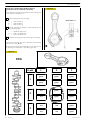
ENGINE FLYWHEEL
Fitting engine flywheel (For F3CE0684B*E003 engines)
Figure 62
b
d
a
c
104283
A
B
VIEW OF HOLES:
VIEW OF
A—B—C
HOLE: D
DETAIL OF PUNCH MARKS ON ENGINE FLYWHEEL FOR PISTON POSITIONS
= Hole on flywheel with one reference mark,
C = Hole on flywheel with one reference mark,
corresponding to the TDC of pistons 3-4.
corresponding to the TDC of pistons 2-5.
= Hole on flywheel with one reference mark,
corresponding to the TDC of pistons 1-6.
D = Hole on flywheel with two reference marks, position
corresponding to 54°.
Fitting engine flywheel (For F3CE0684A*E001 engines)
Figure 63
119482
A
B
DETAIL OF PUNCH MARKS ON ENGINE FLYWHEEL FOR PISTON POSITIONS
= Hole on flywheel with one reference mark,
C = Hole on flywheel with one reference mark,
corresponding to the TDC of pistons 3-4.
corresponding to the TDC of pistons 2-5.
= Hole on flywheel with one reference mark,
corresponding to the TDC of pistons 1-6.
Print P2D32C005 E
D = Hole on flywheel with two reference marks, position
corresponding to 54°.
Base - May 2007
20
SECTION 3 - INDUSTRIAL APPLICATION
F3C CURSOR ENGINES
Fitting camshaft
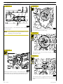
Figure 64
Figure 66
104286
60570
Position the crankshaft with the pistons 1 and 6 at the top dead
centre (T.D.C.).
This situation occurs when:
1. The hole with reference mark (5) of the engine flywheel
(4) can be seen through the inspection window.
2. The tool 99360612 (1), through the seat (2) of the engine
speed sensor, enters the hole (3) in the engine flywheel (4).
If this condition does not occur, turn the engine flywheel (4)
appropriately.
Remove the tool 99360612 (1).
- Apply the gauge 99395219 (1). Check and adjust the
position of the link rod (3) for the idle gear. Lock the screw
(2) to the required torque.
Figure 65
Figure 67
73843
60571
Fit the camshaft (4), positioning it observing the reference
marks (→) as shown in the figure.
- Fit the idle gear (1) back on and lock the screws (2) to the
required torque.
Lubricate the seal (3) and fit it on the shoulder plate (2).
Mount the shoulder plate (2) with the sheet metal gasket (1)
and tighten the screws (5) to the required torque.
Base - May 2007
Print P2D32C005 E
F3C CURSOR ENGINES
SECTION 3 - INDUSTRIAL APPLICATION
Figure 68
21
Figure 70
5
60572
Position the gear (2) on the camshaft so that the 4 slots are
centred with the holes for fixing the camshaft, without fully
locking the screws (5).
Using the dial gauge with a magnetic base (1), check that the
clearance between the gears (2 and 3) is 0.073 — 0.195 mm;
if this is not so, adjust the clearance as follows:
104260
Mount:
- The injectors (1) and, using a torque wrench, lock the
bracket fixing screws to a torque of 26 Nm.
- The crosspieces (2) on the valve stem, all with the largest
hole on the same side.
- Loosen the screws (4) fixing the idle gear (3).
- Loosen the screw (2, Figure 65) fixing the link rod. Shift
the link rod (3, Figure 65) to obtain the required
clearance.
- Lock the screw (2, Figure 65) fixing the link rod and
screws (4, Figure 68) fixing the idle gear to the required
torque.
Fitting rocker-arm shaft assembly
Fitting pump-injectors
Figure 71
Figure 69
NOTE Before refitting the rocker-arm shaft assembly, make
sure that all the adjustment screws have been fully
unscrewed.
104243
Fit the seals (1) (2) (3) on the injectors.
Print P2D32C005 E
116814
Apply the tool 99360553 (1) to the rocker arm shaft (2) and
mount the shaft on the cylinder head.
Base - May 2007
22
SECTION 3 - INDUSTRIAL APPLICATION
F3C CURSOR ENGINES
Camshaft timing
Figure 72
(For F3CE0684B*E003)
Figure 74
70567A
SCHEME OF SCREW TIGHTENING SEQUENCE
SECURING ROCKER ARMS
104316
Screw screws (1 - 2 - 3) until rocker arms are brought to
contact relating seats on cylinder head, tighten the screws
according to sequence indicated in figure operating in two
steps as indicated in successive figure.
Using the tool, turn the engine flywheel (1) in the direction of
rotation of the engine so as to take the piston of cylinder no.1
to approximately the T.D.C. in the phase of combustion.
This condition occurs when the hole with one reference mark
(4), after the hole with two reference marks (5) on the engine
flywheel (1), can be seen.
Camshaft timing
(For F3CE0684A*E001)
Figure 75
Figure 73
α
104261
Lock the screws (2) fixing the rocker-arm shaft as follows:
- 1st phase: tightening to a torque of 80 Nm (8 kgm) with
the torque wrench (1);
- 2nd phase: closing with an angle of 60° using the tool
99395216 (3).
Mount the electric wiring on the electro-injectors.
Base - May 2007
104789
Using the tool, turn the engine flywheel (1) in the direction of
rotation of the engine so as to take the piston of cylinder no.1
to approximately the T.D.C. in the phase of combustion.
This condition occurs when the hole with one reference mark
(4), after the hole with two reference marks (5) on the engine
flywheel (1), can be seen.
Print P2D32C005 E
F3C CURSOR ENGINES
SECTION 3 - INDUSTRIAL APPLICATION
23
Figure 78
Figure 76
104286
104288
The exact position of piston no.1 at the T.D.C. is obtained
when in the above-described conditions the tool 99360612
(1) goes through the seat (2) of the engine speed sensor into
the hole (3) in the engine flywheel (4).
If this is not the case, turn and adjust the engine flywheel (4)
appropriately.
Remove the tool 99360612 (1).
Figure 77
The camshaft is in step if at the cam lift values of 5.31 ±0.05 mm
there are the following conditions:
1) the hole marked with a notch (5) can be seen through the
inspection window;
2) the tool 99360612 (1) through the seat (2) of the engine
speed sensor goes into the hole (3) in the engine
flywheel (4).
Figure 79
60573
Set the dial gauge with the magnetic base (1) with the rod on
the roller (2) of the rocker arm that governs the injector of
cylinder no.1 and pre-load it by 6 mm.
With tool 99360321, turn the crankshaft clockwise until the
pointer of the dial gauge reaches the minimum value beyond
which it can no longer fall.
60575
If you do not obtain the conditions illustrated in Figure 78 and
described in points 1 and 2, proceed as follows:
1) loosen the screws (2) securing the gear (1) to the camshaft
and utilize the slots (see Figure 80) on the gear (1);
Reset the dial gauge.
2) turn the engine flywheel appropriately so as to bring about
the conditions described in points 1 and 2 Figure 78, it
being understood that the cam lift must not change at all;
Turn the engine flywheel anticlockwise until the dial gauge gives
a reading for the lift of the cam of the camshaft of 5.31 ±0.05 mm.
3) lock the screws (2) and repeat the check as described
above.
Tighten the screws (2) to the required torque.
Print P2D32C005 E
Base - May 2007
24
SECTION 3 - INDUSTRIAL APPLICATION
F3C CURSOR ENGINES
Mount the gear (2) Figure 80 with the 4 slots (1) centred with
the fixing holes of the camshaft, locking the relevant screws to
the required tightening torque.
Check the timing of the shaft by first turning the flywheel
clockwise to discharge the cylinder completely and then turn
the flywheel anticlockwise until the dial gauge gives a reading
of 5.31 ± 0.05.
Check the timing conditions described in Figure 78.
Figure 80
Phonic wheel timing
Figure 82
71778
When the adjustment with the slots (1) is not enough to make
up the phase difference and the camshaft turns because it
becomes integral with the gear (2); as a result, the reference
value of the cam lift varies, in this situation it is necessary to
proceed as follows:
1) lock the screws (2, Figure 79) and turn the engine flywheel
clockwise by approx. 1/2 turn;
2) turn the engine flywheel anticlockwise until the dial gauge
gives a reading of the lift of the cam of the camshaft of 5.31
± 0.05 mm;
3) take out the screws (2, Figure 79) and remove the gear (1)
from the camshaft.
Figure 81
104289
Turn the crankshaft by taking the piston of cylinder no. 1 into
the compression phase at T.D.C.; turn the flywheel in the
opposite direction to the normal direction of rotation by
approximately 1/4 of a turn.
Again turn the flywheel in its normal direction of rotation until
you see the hole marked with the double notch (4) through
the inspection hole under the flywheel housing. Insert tool
99360612 (5) into the seat of the flywheel sensor (6).
Insert the tool 99360613 (2), via the seat of the phase sensor,
onto the tooth obtained on the phonic wheel.
104286
Should inserting the tool (2) prove difficult, loosen the screws
(3) and adjust the phonic wheel (1) appropriately so that the
tool (2) gets positioned on the tooth correctly. Go ahead and
tighten the screws (3).
Turn the flywheel (4) again to bring about the following
conditions:
- a notch (5) can be seen through the inspection window;
- the tool 99360612 (1) inserted to the bottom of the seat
of the engine speed sensor (2) and (3).
Base - May 2007
Print P2D32C005 E
F3C CURSOR ENGINES
SECTION 3 - INDUSTRIAL APPLICATION
25
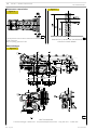
Intake and exhaust rocker play adjustment and pre-loading of rockers controlling pump injectors
Figure 83
119499
ADJUSTING INTAKE/EXHAUST ROCKERS AND INJECTION
Adjustment of clearances between rockers and valve studs
and preloading of pump injector rockers should be carried out
with extreme care.
Bring the cylinder under examination to the firing stage, the
valves of this cylinder remain closed while the valves of the
other cylinder in the pair can be adjusted.
The cylinder pairs are 1-6,2-5,3-4.
Strictly adhere to directions and data given on the table below.
and
Adjusting
clearances
between
rockers
intake/exhaust/valve studs:
- Use a box wrench to loosen the adjusting screw locking
nut (1).
- Insert the feeler gauge blade (3).
- Use a suitable wrench to screw the adjusting screw in or
out as required.
- Ensure the feeler gauge blade (3) can slide between the
parts concerned with a slight friction.
- Hold the screw still while tightening the nut (1).
Setting pump-injector rocker preloading:
- Use a box wrench to loosen the nut fastening the
adjusting screw for rocker arm (5) controlling
pump-injector (6).
- With a suitable wrench (4) tighten the adjusting screw
until the pumping element reaches its-end-of-stroke
point.
Print P2D32C005 E
- Lock the adjusting screw to a torque of 5 Nm (0.5 kgm)
by means of a torque wrench.
- Back off the adjusting screw 1/2 to 3/4 turn.
- Tighten the lock nut.
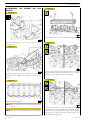
FIRING ORDER 1-4-2-6-3-5
Clockwise
start-up
and rotation
Adjusting
cylinder
valve no.
6
Adjusting
clearance
of cylinder
valve no.
1
Adjusting
pre-loading
of cylinder
injector no.
5
1 and 6 at TDC
120º
120º
120º
120º
120º
3
5
1
4
2
4
2
6
3
5
1
4
2
6
3
In order to properly carry out the above-mentioned
adjustments, follow the sequence specified in the table,
checking the exact position in each rotation phase by
means of pin 99360612, to be inserted in the 11th hole
in each of the three sectors with 18 holes each.
Base - May 2007
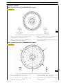
26
SECTION 3 - INDUSTRIAL APPLICATION
F3C CURSOR ENGINES
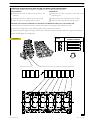
Figure 84
Figure 85
85480
Fit the timing cover (1).
85481
Apply LOCTITE 5970 on the breather body (1) forming a
bead (2) as shown in figure ∅ 1,5 + 0,5
0,2
Tighten the fastening screws on the rocker arm cover
(1) in the order shown in figure 79.
!
Fit the blow-by casing (7) with corresponding seal and tighten
the screws (8) at the specified torque.
Fit the filter (5) with the corresponding seals (4 and 6).
NOTE Fit the breather body (1) within 10 after applying the
sealant.
The one-way filter (5) must be fitted with the two
reinforcement bars visible as shown in the figure.
Fasten the cover (3) and fasten the screws (2) at the specified
torque.
Figure 86
17
14
13
1
4
5
8
18
9
19
10
20
11
16
15
12
2
3
6
7
45363
DIAGRAM OF ROCKER ARM CAP FIXING SCREWS
TIGHTENING SEQUENCE
Base - May 2007
Print P2D32C005 E
F3C CURSOR ENGINES
27
SECTION 3 - INDUSTRIAL APPLICATION
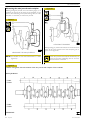
ENGINE COMPLETION
Figure 90
Figure 87
101607
Fit the suction rose (1) and tighten the fastening screws at the
specified torque.
119500
DIAGRAM OF ENGINE OIL SUMP FIXING SCREWS
TIGHTENING SEQUENCE
Only for engine F3CE0684A*E001
Figure 88
101606
Figure 91
Arrange the seal (4) on the oil sump (1), arrange the shim (2),
fit the sump on the crankcase and tighten the screws (3) at the
specified torque.
Only for engine F3CE0684B*E003
Figure 89
116817
Fasten the intake manifold (1) and tighten the screws (2) at the
specified torque.
104784
Arrange the seal (4) on the oil sump (1), arrange the shim (2),
fit the sump on the crankcase and tighten the screws (3) at the
specified torque.
Print P2D32C005 E
NOTE The inlet fitting may have different positions
according to the engine type.
Base - May 2007
28
SECTION 3 - INDUSTRIAL APPLICATION
F3C CURSOR ENGINES
Figure 92
Figure 94
101605
104254
Fit heat exchanger (2) with its respective gasket, then tighten
fastening screws (1) to the torque specified and according to
the sequence indicated in Figure 92.
Fit the oil filters (1) on the relevant supports as follows:
-
oil the seals;
screw the filters down for the seals to make contact with
the supporting bases;
tighten the filters to a torque of 35 to 40 Nm.
Fit, with the respective gaskets.
-
the fuel pump (2);
fuel filter unit (3) with its respective pipes (1);
connect the pipes (1) to the fuel pump (2).
Figure 95
Figure 93
119490
45361
DIAGRAM OF HEAT EXCHANGER FIXING SCREWS
TIGHTENING SEQUENCE
Base - May 2007
Fit the hydraulic coupling (2) onto the flywheel casing.
Tighten the fastening screws (1).
Tighten the screws (1) at a torque of 45 Nm.
Print P2D32C005 E
F3C CURSOR ENGINES
SECTION 3 - INDUSTRIAL APPLICATION
Figure 96
29
Figure 98
119489
Fit the oil return pipe (1).
119486
Fasten the screws (2) fastening the pipe (1) to the crankcase.
Tighten the screws (2) at a torque of 23 Nm.
Fit the power turbine (2) onto the hydraulic coupling.
NOTE Lubricate the accommodation seat on the hydraulic
coupling with Loctite AS600 before fitting the
power turbine.
When fitting the power turbine on the hydraulic coupling, pay
attention to the meshing of the gears which transmit motion
from one element to the other.
Tighten the fastening screws (1).
Tighten the screws (1) at a torque of 40 Nm.
Figure 97
Figure 99
119485
Fit the exhaust manifold.
119488
Fit the oil delivery pipe (2) to the hydraulic coupling fastening
it with fittings (1) and (3).
Print P2D32C005 E
NOTE Remove the seals between the exhaust manifold
and the crankcase
Insert the seals (2) between the fastening screws (1) and the
intake manifold.
Base - May 2007
30
SECTION 3 - INDUSTRIAL APPLICATION
F3C CURSOR ENGINES
Figure 100
Figure 102
119481
Position the clamps (1) and (2) respectively on the
turbocharger and on the power turbine.
119484
Fit the turbocharger (2) on the exhaust manifold making sure
that the seal (4) is positioned between the two parts.
Fit the connection manifold (3) between turbocharger and
power turbine.
Fasten the manifold to the two turbines by means of the
clamps (1) and (2).
Position the shims (3) on the fastening screws (1) and tighten
them at a torque of 70 Nm
Fasten the nuts (5) and tighten them at a torque of 45 Nm.
Figure 101
Figure 103
119480
119483
Fit the oil delivery pipe (1) onto the turbocharger and fasten
with the fitting (2) on the filter unit and with the screws (6) to
the turbocharger itself.
Insert the oil return pipe (4) in the crankcase and fasten it with
the screws (3).
The fasten the pipe (4) to the turbocharger by means of the
screws (5).
Base - May 2007
Tightening the fixing screws to the prescribed torque, mount:
- the starter motor (1);
- the control unit (2) and its support;
- the oil dipstick (3) in the crankcase.
Check the state of the flexible elements of the control
unit support and change them if they have
deteriorated.
Print P2D32C005 E
F3C CURSOR ENGINES
SECTION 3 - INDUSTRIAL APPLICATION
Only for engine: F3CE0684A*E001
Figure 104
Figure 106
104249
104251
Fit, with the following parts:
-
31
Using a suitable tool (3), work in the direction of the arrow on
the tightener (2) and mount the belt (1).
automatic tightener support (1);
automatic tightener (2);
damper flywheel (3) and pulley beneath;
fixed tightener (5);
water pump (7);
the pulley (4);
pipe comprehensive of coolant (6);
thermostat assembly (8).
NOTE The tighteners are automatic, so there are no other
adjustments after assembly.
Only for engine: F3CE0684B*E003
Figure 105
Figure 107
106223
99360
Mount the following, tightening the screws to the prescribed
torque:
- the supports (1 and 3);
- alternator (2).
Print P2D32C005 E
- driving belt.
To mount belt (1), belt tensioner (2) has to be operated by
proper tooling (3) according to the direction indicated by the
arrow in Figure.
Base - May 2007
32
SECTION 3 - INDUSTRIAL APPLICATION
F3C CURSOR ENGINES
For all types
Figure 108
Only for F3CE0684B*E003
Figure 110
104247
Fit the arm 99360585 onto the engine lifting hooks and hook
the arm onto the hoist.
Take out the screws fixing the brackets 99361036 to the
rotary stand. Lift the engine and remove the above-mentioned
brackets from it.
Complete engine assembly with the following parts, tightening
the fixing screws or nuts to the prescribed torque:
- mount the drive (1);
- mount the engine supports;
104782
Assemble the following components and tighten their fixtures
to the specified torque:
-
Figure 109
the fixed belt tightening roller (1);
the support (2);
the automatic belt tightener (3);
the damping flywheel (4) and the pulley beneath it;
all the coolant pipes (5);
the water pump (6);
the fixed belt tightening roller (7);
the thermostat assembly (8).
119487
Mount the oil pressure adjuster valve (1).
Fasten and tighten the screw (2) fastening the hydraulic
coupling to the flywheel casing.
Base - May 2007
Print P2D32C005 E
F3C CURSOR ENGINES
SECTION 3 - INDUSTRIAL APPLICATION
33
Figure 112
Figure 111
104780
104781
Assemble the belt on the pulleys and tightening rollers, making
sure that it is correctly inserted in its seats.
Assemble the alternator support (3) on the engine and tighten
the locking screws to the specified torque.
Assemble the alternator (4) and tighten the locking screws to
the specified torque value.
Assemble the compressor (1) complete with its support (2)
on the engine and tighten the locking screws to the specified
torque.
Print P2D32C005 E
!
The belt tighteners are of the automatic type and so
no further adjustment is required after assembly.
Base - May 2007
34
SECTION 3 - INDUSTRIAL APPLICATION
Base - May 2007
F3C CURSOR ENGINES
Print P2D32C005 E
F3C CURSOR ENGINES
SECTION 3 - INDUSTRIAL APPLICATION
35
PART TWO ELECTRICAL EQUIPMENT
Print P2D32C005 E
Base - May 2007
36
SECTION 3 - INDUSTRIAL APPLICATION
Base - May 2007
F3C CURSOR ENGINES
Print P2D32C005 E
F3C CURSOR ENGINES
SECTION 3 - INDUSTRIAL APPLICATION
37
Components on the engine F3CE0684A*E001
Figure 1
ENGINE RIGHT-HAND SIDE VIEW
110586
Figure 2
110585
ENGINE LEFT-HAND SIDE VIEW
A. Resistance for engine warming - B. Fuel filter clogged signalling switch - C. Fuel temperature sensor - D. Engine rpm sensor
on camshaft - E. Starter motor - G. Alternator - H. Temperature/air pressure sensor - I. Conditioner compressor L. EDC 7 control unit - M. Connector on engine head for connection with injector solenoid valves N. Water temperature for EDC 7 - O. Water temperature sensor - P. Oil pressure/temperature transmitter Q. Engine speed on flywheel sensor - R. Low oil pressure transmitter.
Print P2D32C005 E
Base - May 2007
38
SECTION 3 - INDUSTRIAL APPLICATION
F3C CURSOR ENGINES
Components on the engine F3CE0684B*E003
Figure 3
ENGINE RIGHT-HAND SIDE VIEW
110593
Figure 4
ENGINE LEFT-HAND SIDE VIEW
110592
A. Resistance for engine warming - B. Fuel filter clogged signalling switch - C. Fuel temperature sensor - D. Engine rpm sensor
on camshaft - E. Starter motor - G. Alternator - H. Temperature/air pressure sensor - I. Conditioner compressor L. EDC 7 control unit - M. Connector on engine head for connection with injector solenoid valves N. Water temperature for EDC 7 - O. Water temperature sensor - P. Oil pressure/temperature transmitter Q. Engine speed on flywheel sensor - R. Low oil pressure transmitter.
Base - May 2007
Print P2D32C005 E
F3C CURSOR ENGINES
SECTION 3 - INDUSTRIAL APPLICATION
39
BLOCK DIAGRAM
Figure 5
116816
KEYS
1. Engine coolant temperature sensor — 2. Oversupply air temperature sensor — 3. Fuel temperature sensor —
4. Oversupply air pressure sensor — 5. Engine oil pressure and temperature sensor - 6. CAL L-H line — 7. Pump-injectors —
8. Remote control switch for pre/post-heating activation — 9. Pre/post-heating resistance — 10. Main remote control switch —
11. Flywheel sensor — 12. Distribution sensor — 13. Primary / secondary brake switch.
Print P2D32C005 E
Base - May 2007
40
SECTION 3 - INDUSTRIAL APPLICATION
F3C CURSOR ENGINES
EDC 7 UC31 electronic control unit
Figure 6
C
A
B
102373
A. Electro-injector connector - B. Chassis connector - C. Sensor connector.
Base - May 2007
Print P2D32C005 E
F3C CURSOR ENGINES
SECTION 3 - INDUSTRIAL APPLICATION
41
EDC control unit PIN-OUT
Electric injector connector ”A”
Figure 7
12
16
11
6
Colour legend
B
black
R
red
U
blue
W
white
P
purple
G
green
N
brown
Y
yellow
O
orange
E
grey
K
pink
ECU
Pin
1
2
3
4
5
6
7
8
9
10
11
12
13
14
15
16
Print P2D32C005 E
102374
1
Colour legend
Black
Black
Black
White
Green
Red
Yellow
Red
Red
Bleu
Green
Purple
5
Function
Solenoid valve for electronic cylinder 5 injection
Solenoid valve for electronic cylinder 6 injection
Solenoid valve for electronic cylinder 4 injection
Solenoid valve for electronic cylinder 1 injection
Solenoid valve for electronic cylinder 3 injection
Solenoid valve for electronic cylinder 2 injection
Free
Free
Free
Free
Solenoid valve for electronic cylinder 2 injection
Solenoid valve for electronic cylinder 3 injection
Solenoid valve for electronic cylinder 1 injection
Solenoid valve for electronic cylinder 4 injection
Solenoid valve for electronic cylinder 6 injection
Solenoid valve for electronic cylinder 5 injection
Base - May 2007
42
SECTION 3 - INDUSTRIAL APPLICATION
F3C CURSOR ENGINES
EDC control unit PIN-OUT
Sensor connector ”C”
Figure 8
Base - May 2007
8
16
9
15
22
1
3
23 30
36
29
4
5
Colour legend
B
black
R
red
U
blue
W
white
P
purple
G
green
N
brown
Y
yellow
O
orange
E
grey
K
pink
ECU
Pin
1÷8
9
10
11÷14
15
16 ÷17
18
19
20÷22
23
24
25
26
27
28
29÷31
32
33
34
35
36
6
102375
Cable colour
W
R
K
O/B
B
W
N
W
Y
O/B
U
O
R
G
W/R
O
Function
Free
Valve gear camshaft sensor
Valve gear camshaft sensor
Free
Coolant temperature sensor
Free
Fuel temperature sensor
Flywheel sensor
Free
Flywheel sensor
Pressure sensor mass / Engine oil temperature
Air temperature/pressure sensor power supply
Coolant temperature sensor
Oil temperature signal from the engine oil temperature/pressure sensor
Oil pressure signal from the engine oil temperature/pressure sensor
Free
Engine oil temperature/pressure sensor power supply
Air temperature/pressure sensor power supply
Air pressure signal from the air temperature/ pressure sensor
Fuel temperature sensor
Air temperature signal from the air temperature / pressure sensor
Print P2D32C005 E
F3C CURSOR ENGINES
SECTION 3 - INDUSTRIAL APPLICATION
43
EDC control unit PIN-OUT
Chassis connector ”B”
Figure 9
71
89
72
54
6
11
1
7
12
53
ECU
Pin
1
2
3
4
5
6
7
8
9
10
11
12
13÷25
26
27
28
29
30
31
32
33
34
35
36÷39
40
41
42
43÷55
56
57
58÷67
68
69÷74
75
76÷88
89
Print P2D32C005 E
Cable
7151
7153
0151
0151
7151
7151
0151
0151
0094
5163
Green
White
9164
2298
35
18
36
17
102376
Function
Free
+30 positive
+30 positive
Free
Ground
Ground
Free
+30 positive
+30 positive
Ground
Ground
Preheating actuation enable relay ground
Free
Free
Free
Free
EDC system diagnosis inducing switch power supply (presetting)
Free
Free
Free
Free
CAN - L line (ECB)
CAN - H line (ECB)
+15 positive
Free
Signal for the sensor of water in the diesel
Free
Free
Free
Free
Free
Preheating actuation enable relay positive
Free
EDC control unit diagnosis K line
Base - May 2007
44
SECTION 3 - INDUSTRIAL APPLICATION
F3C CURSOR ENGINES
INJECTOR PUMP
Figure 10
102405
INJECTOR SECTION
The new pump injectors are capable, thanks to the higher injection pressure, of atomizing the fuel in the combustion chamber to
a greater extent, thus improving combustion and therefore reducing the polluting exhaust emissions.
The fuel pressure damper situated on the discharge line
between the fuel filter and the cylinder head, has the function
of buffering against the return pressure on the discharge line
and on the filter due to the increase of the injection pressure.
Figure 11
102606
FUEL PRESSURE DAMPER
Base - May 2007
Print P2D32C005 E
F3C CURSOR ENGINES
SECTION 3 - INDUSTRIAL APPLICATION
45
Engine coolant temperature sensor
This N.T.C. type sensor located on the water outlet sump on the engine head left measures coolant temperature for the various
operating logics with a hot or cold engine and identifies injection enrichment requirements for a cold engine or fuel reduction
requirements for a hot engine.
It is connected to electronic center pins 15/26.
Sensor behavior as a function of temperature:
- 10 °C
8.10 ÷ 10.77 kOhm
+ 20 °C
2.28 ÷ 2.72 kOhm
+ 80 °C
0.29 ÷ 0.364 kOhm
At 60 to 90 _C, voltage at A5 and A22 ranges from 0.6 to 2.4V.
Figure 12
104266
Description
Cable colour
To EDC center pin 15 (Sensor connector ”C”)
K
To EDC center pin 26 (Sensor connector ”C”)
Y
Print P2D32C005 E
Base - May 2007
46
SECTION 3 - INDUSTRIAL APPLICATION
F3C CURSOR ENGINES
Fuel temperature sensor
Specifications
Supplier
Max. tightening torque
BOSCH
35 Nm
Figure 13
104267
Description
Cable colour
To pin 18 of EDC control unit (Sensor connector ”C”)
O/B
To pin 35 of EDC control unit (Sensor connector ”C”)
W/R
Base - May 2007
Print P2D32C005 E
F3C CURSOR ENGINES
SECTION 3 - INDUSTRIAL APPLICATION
47
.
Flywheel pulse transmitter
Specifications
Supplier
Max. tightening torque
BOSCH
8 ± 2 Nm
Figure 14
104269
Description
Cable colour
To pin 19 of EDC control unit (Sensor connector ”C”)
B
To pin 23 of EDC control unit (Sensor connector ”C”)
W
Print P2D32C005 E
Base - May 2007
48
SECTION 3 - INDUSTRIAL APPLICATION
F3C CURSOR ENGINES
Distribution pulse transmitter
Features
Vendor
Torque
Resistance
BOSCH
8 ± 2 Nm
880 ÷ 920 Ω
This induction type sensor located on the camshaft generates signals obtained from the magnetic flow lines that close through the
6 plus 1 phase teeth of a sound wheel mounted on the shaft.
The electronic center uses the signal generated by this sensor as an injection step signal.
Though electrically identical to engine rpm sensor mounted in the camshaft in is NOT interchangeable with it as it cable is shorter
and it features a larger diameter.
This sensor’s air gap is NOT ADJUSTABLE.
Figure 15
104269
Description
Cable colour
To EDC center pin 9 (Sensor connector ”C”)
W
To EDC center pin 10 (Sensor connector ”C”)
R
Base - May 2007
Print P2D32C005 E
F3C CURSOR ENGINES
SECTION 3 - INDUSTRIAL APPLICATION
49
Air pressure/temperature sensor (85156).
This component incorporates a temperature sensor and a
pressure sensor.
Figure 16
IIt replaces the temperature sensors (85155) and pressure
sensors (85154) available in the preceding systems.
It is fitted onto the intake manifold and measures the
maximum supplied air flow rate used to accurately calculate
the amount of fuel to be injected at every cycle.
The sensor is powered with 5 V.
The output voltage is proportional to the pressure or
temperature measured by the sensor.
Pin (EDC)
Pin (EDC)
Pin (EDC)
25/C - 33/C
36/C
34/C
Power supply
Temperature
Pressure
50324
Sensor external view
Oil temperature/pressure sensor (42030 / 47032)
This component is identical to the air pressure/temperature
sensor and replaced single sensors 47032 / 42030.
Figure 17
It is fitted onto the engine oil filter, in a horizontal position.
It measures the engine oil temperature and pressure.
The measured signal is sent to the EDC control unit which
controls, in turn, the indicator instrument on the dashboard
(low pressure warning lights / gauge).
Pin (EDC)
Pin (EDC)
Pin (EDC)
24/C - 32/C
27/C
28/C
Power supply
Temperature
Pressure
The engine oil temperature is used only by the EDC control
unit.
50323
Linking connector
Figure 18
Ref
Ref.
Description
1
Control unit pin
Oil
Air
Ground
24C
25C
2
Temp. Sign.
27C
36C
3
+5
32C
33C
4
Press. Sign.
28C
34C
50344
Wiring diagram
Print P2D32C005 E
Base - May 2007
50
SECTION 3 - INDUSTRIAL APPLICATION
F3C CURSOR ENGINES
Alternator for F3CE0684B*E003
Supplier
Technical features
ISKRA
14V - 175A
Figure 19
104313
Base - May 2007
Print P2D32C005 E
F3C CURSOR ENGINES
SECTION 3 - INDUSTRIAL APPLICATION
51
Alternator for F3CE0684A*E001
Supplier
Technical features
LEECE NEVILLE
12V - 185A
Figure 20
104314
Pin
Description
R
AC Connector
L
Driver warning light connector
B-
Negative
B+
Positive
Print P2D32C005 E
Base - May 2007
52
SECTION 3 - INDUSTRIAL APPLICATION
F3C CURSOR ENGINES
Starting motor
Figure 21
104315
F3CE0684A*E001
Supplier
Type
DENSO
428000 - 4250
Voltage
Nominal output
Base - May 2007
F3CE0684B*E003
228000 - 7550
24 V
5.5 kW
7.8 kW
Print P2D32C005 E
F3C CURSOR ENGINES
SECTION 3 - INDUSTRIAL APPLICATION
53
PRE/POST-HEATING RESISTANCE
The resistance is ~ 0,7 Ohm.
Such resistance is placed between the cylinder head and the suction manifold. It is used to heat up air during pre/post-heating
operations.
When the ignition key is inserted, should any one of the temperature sensors — water, air, gas oil — detect a value below 10°C,
the electronic control unit will activate pre/post-heating and turn on the relevant dashboard warning light for a variable time
depending on the temperature.
After that time, the warning light starts blinking thus informing the driver that the engine can be started.
When the engine is running the warning light goes off, while the resistance is being fed for a certain time as a result of post-heating.
If the engine is not started, with the warning light flashing, in 20 / 25 seconds, the operation is cancelled to prevent draining the
battery.
On the contrary, if reference temperatures are over 10°C, when the ignition key is inserted the warning light comes on for about
2 seconds and carries out the test and then goes out to signal that the engine can be started.
Figure 22
(F3CE0684A*E001)
119966
(F3CE0684AB*E003)
119967
Print P2D32C005 E
Base - May 2007
54
SECTION 3 - INDUSTRIAL APPLICATION
F3C CURSOR ENGINES
EDC SYSTEM FUNCTIONS
The EDC 7 UC31 electronic center manages the following main functions:
Fuel injection
Accessory functions such as cruise control, speed limiter, PTO and the like
Self-diagnosis
Recovery
It also enables:
Interfacing with other electronic systems (if any) available on the vehicle
Diagnosis
Fuel dosing
Fuel dosing is calculated based on:
- accelerator pedal position
- engine rpm
- quantity of air admitted.
The result can be corrected based on:
- water temperature
or to prevent:
- noise
- fumes
- overloads
- overheating
Pressure can be adjusted in case of:
- engine brake actuation
- external device actuation (e.g. speed reducer, cruise control)
- serious defects involving load reduction or engine stop.
After determining the mass of air introduced by measuring its volume and temperature, the center calculates the corresponding
mass of fuel to be injected into the cylinder involved, with account also taken of gas oil temperature.
Delivery correction based on water temperature
When cold, the engine encounters greater operating resistance, mechanical friction is high, oil is till very viscous and operating plays
are not optimized yet.
Fuel injected also tends to condense on cold metal surfaces.
Fuel dosing with a cold engine is therefore greater than when hot.
Delivery correction to prevent noise, fumes or overloads
Behaviors that could lead to the defects under review are well known, so the designer has added specific instructions to the center
to prevent them.
De-rating
In the event of engine overheating, decreasing delivery proportionally to the temperature reached by the coolant changes injection.
Base - May 2007
Print P2D32C005 E
F3C CURSOR ENGINES
SECTION 3 - INDUSTRIAL APPLICATION
55
Injection lead electronic control
Injection lead, or the start of fuel delivery expressed in degrees, can differ from one injection to the next, even from one cylinder
to another and is calculated similarly to delivery according to engine load, namely, accelerator position, engine rpm and air admitted.
Lead is corrected as required:
- during acceleration
- according to water temperature
and to obtain:
- reduced emissions, noise abatement and no overload
- better vehicle acceleration
High injection lead is set at start, based on water temperature.
Delivery start feedback is given by injection electro valve impedance variation.
Engine start
Cylinder 1 step and recognition signal synchronization (flywheel and drive shaft sensors) takes place at first engine turns. Accelerator
pedal signal is ignored at start. Star delivery is set exclusively based on water temperature, via a specific map. The center enables
the accelerator pedal, when it detects flywheel acceleration and rpm such as to consider the engine as started and no longer drawn
by the starter motor.
Cold start
Pre-post reheating is activated when even only one of the three water, air or gas oil temperature sensors records a temperature
of below 10 _C. The pre-heat warning light goes on when the ignition key is inserted and stays on for a variable period of time
according to temperature, while the intake duct input resistor heats the air, then starts blinking, at which point the engine can be
started.
The warning light switches off with the engine revving, while the resistor continues being fed for a variable period of time to
complete post-heating. The operation is cancelled to avoid uselessly discharging the batteries if the engine is not started within 20
÷ 25 seconds with the warning light blinking. The pre-heat curve is also variable based on battery voltage.
Hot start
On inserting the ignition key the warning light goes on for some 2 seconds for a short test and then switches off when all reference
temperatures are above 10 _C. The engine can be started at this point.
Run Up
When the ignition key is inserted, the center transfers data stored at previous engine stop to the main memory (Cf. After run),
and diagnoses the system.
After Run
At each engine stop with the ignition key, the center still remains fed by the main relay for a few seconds, to enable the
microprocessor to transfer some data from the main volatile memory to an non-volatile, cancelable and rewritable (Eeprom)
memory to make tem available for the next start (Cf. Run Up).
These data essentially consists of:
- miscellaneous settings, such as engine idling and the like
- settings of some components
- breakdown memory
The process lasts for some seconds, typically from 2 to 7 according to the amount of data to be stored, after which the ECU sends
a command to the main relay and makes it disconnect from the battery.
Print P2D32C005 E
Base - May 2007
56
SECTION 3 - INDUSTRIAL APPLICATION
F3C CURSOR ENGINES
This procedure must never be interrupted, by cutting the engine off from the battery cutout or disconnecting the latter before
10 seconds at least after engine cutout.
In this case, system operation is guaranteed until the fifth improper engine cutout, after which an error is stored in the breakdown
memory and the engine operates at lower performance at next start while the EDC warning light stays on.
Repeated procedure interruptions could in fact lead to center damage.
Cut-off
It refers to the supply cut-off function during deceleration.
Cylinder Balancing
Individual cylinder balancing contributes to increasing comfort and operability.
This function enables individual personalized fuel delivery control and delivery start for each cylinder, even differently between each
cylinder, to compensate for injector hydraulic tolerances.
The flow (rating feature) differences between the various injectors cannot be evaluated directly by the control unit. This information
is provided by the entry of the codes for every single injector, by means of the diagnosis instrument.
Synchronization search
The center can anyhow recognize the cylinder to inject fuel into even in the absence of a signal from the camshaft sensor.
If this occurs when the engine is already started, combustion sequence is already acquired, so the center continues with the
sequence it is already synchronized on; if it occurs with the engine stopped, the center only actuates one electro valve. Injection
occurs onside that cylinder within 2 shaft revs at the utmost so the center is only required to synchronize on the firing sequence
and start the engine.
Base - May 2007
Print P2D32C005 E
F3C CURSOR ENGINES
SECTION 3 - INDUSTRIAL APPLICATION
57
PART THREE - TROUBLESHOOTING
Print P2D32C005 E
Base - May 2007
58
SECTION 3 - INDUSTRIAL APPLICATION
Base - May 2007
F3C CURSOR ENGINES
Print P2D32C005 E
F3C CURSOR ENGINES
PREFACE
A successful troubleshooting is carried out with the
competence acquired by years of experience and attending
training courses.
When the user complains for bad efficiency or working
anomaly, his indications must be kept into proper
consideration using them to acquire any useful information to
focus the intervention.
After the detection of the existing anomaly, it is
recommended to proceed with the operations of
troubleshooting by decoding the auto-troubleshooting data
provided by the EDC system electronic central unit.
SECTION 3 - INDUSTRIAL APPLICATION
59
Every time there is a breakdown claim and this breakdown is
actually detected, it is necessary to proceed inquiring the
electronic unit in one of the ways indicated and then proceed
with the diagnostic research making trials and tests in order to
have a picture of the working conditions and identify the root
causes of the anomaly.
In case the electronic device is not providing any indication, it
will be necessary to proceed relying on the experience,
adopting traditional diagnosis procedures.
In order to compensate the operators’ lack of experience in
this new system, we are hereby providing the USER’s
GUIDELINE FOR TROUBLESHOOTING in the following
pages.
The continuous efficiency tests of the components connected
to, and the check of working conditions of the entire system
carried out during working, can offer an important diagnosis
indication, available through the decoding of the
”failure/anomaly” codes issued by blinking of the failure led:
the ”blink-code” (whether programmed).
Please consider that the interpretation of the indications
provided by the blink-code is not sufficient to guarantee the
solution to the existing anomalies.
Use of appropriate diagnostic tools allows to decode the error
codes, to exploit the internal database and to obtain other
information for identifying the origin of the fault.
Print P2D32C005 E
Any kind of operation on the electronic center unit
must be executed by qualified personnel, duly
authorized.
Any unauthorized tamper will involve decay of
after-sales service in warranty.
Base - May 2007
60
SECTION 3 - INDUSTRIAL APPLICATION
F3C CURSOR ENGINES
FAULT CODE
DTC
Faulty component
Vehicle 1 (Sensors/Plausibility checks)
1.1.9
PLAUSIBILITY +15
1.1.A
PLAUSIBILITY +50
Vehicle 2 (Warning lights/Relays/Actuators)
1.2.5
MAIN RELAY
1.2.6
BATTERY VOLTAGE
1.2.8
MAIN RELAY - SHORT CIRCUIT TO BATTERY
1.2.9
CONDITIONER COMPRESSOR RELAY
1.2.B
THERMO STARTER RELAY 1 (HEATER)
1.2.E
PRE/POST-HEATER CONTROL SYSTEM (ACTIVE)
2.2.5
INTERRUPTED AFTER-RUN
2.2.8
MAIN RELAY - SHORT CIRCUIT TO EARTH
Engine 1 (temperature and pressure sensors)
1.3.1
COOLANT TEMPERATURE SENSOR
1.3.2
COOLANT TEMPERATURE SENSOR (TEST)
1.3.3
TURBOCHARGER AIR TEMPERATURE SENSOR
1.3.4
SUPERCHARGER AIR PRESSURE SENSOR
1.3.5
FUEL TEMPERATURE
1.3.8
OIL PRESSURE SENSOR
1.3.A
OIL TEMPERATURE SENSOR
2.3.2
COOLANT TEMPERATURE SENSOR ABSOLUTE TEST
2.3.8
LOW OIL PRESSURE
2.3.A
HIGH OIL TEMPERATURE
Engine 2 (speed sensors/actuators)
1.4.1
CRANKSHAFT SPEED SENSOR
1.4.2
ENGINE OPERATION WITH CAMSHAFT SENSOR ONLY
1.4.3
CAMSHAFT SENSOR
1.4.4
PLAUSIBILITY BETWEEN FLYWHEEL SENSOR AND CAMSHAFT
Damage information
1.4.D
ENGINE OVERSPEED
3.9.E
TURBO PROTECTION TORQUE LIMITER
4.9.E
ENGINE PROTECTION TORQUE LIMITER
6.9.E
TORQUE LIMITER DUE TO LIMITED INJECTED QUANTITY
Fuel metering
1.5.1
INJECTOR CYLINDER 1
1.5.2
INJECTOR CYLINDER 2
1.5.3
INJECTOR CYLINDER 3
1.5.4
INJECTOR CYLINDER 4
1.5.5
INJECTOR CYLINDER 5
1.5.6
INJECTOR CYLINDER 6
Base - May 2007
Print P2D32C005 E
F3C CURSOR ENGINES
SECTION 3 - INDUSTRIAL APPLICATION
DTC
61
Faulty component
Injectors 1
1.6.1
INJECTOR CYLINDER 1 / SHORT CIRCUIT
1.6.2
INJECTOR CYLINDER 2 / SHORT CIRCUIT
1.6.3
INJECTOR CYLINDER 3 / SHORT CIRCUIT
1.6.4
INJECTOR CYLINDER 4 / SHORT CIRCUIT
1.6.5
INJECTOR CYLINDER 5 / SHORT CIRCUIT
1.6.6
INJECTOR CYLINDER 6 / SHORT CIRCUIT
1.6.7
INJECTOR CYLINDER 1 / SHORT CIRCUIT
1.6.8
INJECTOR CYLINDER 2 / SHORT CIRCUIT
1.6.9
INJECTOR CYLINDER 3 / SHORT CIRCUIT
1.6.A
INJECTOR CYLINDER 4 / SHORT CIRCUIT
1.6.B
INJECTOR CYLINDER 5 / SHORT CIRCUIT
1.6.C
INJECTOR CYLINDER 6 / SHORT CIRCUIT
1.6.E
MINIMUM NUMBER OF INJECTIONS NOT REACHED: SWITCHING THE ENGINE OFF
Injectors 2
1.7.1
ROW 1 SC
1.7.3
ROW 2 SC
1.7.C
ROW 1 INJECTOR CONTROL (IN ECU)
1.7.F
ESTIMATED INJECTED QUANTITY ERROR (NIMA PROGRAM)
2.7.C
ROW 2 INJECTOR CONTROL (IN ECU)
Turbocharger and turbine speed system
1.9.E
TORQUE LIMITER FOR LIMITING SMOKINESS
Interfaces 1 (CAN-Bus)
1.B.1
ERROR ON CAN CONTROLLER A
1.B.3
ERROR ON CAN CONTROLLER C
1.B.5
CAN TIMEOUT MESSAGE VM2EDC
2.B.4
CAN TIMEOUT MESSAGE BC2EDC2
Interfaces 2 (CAN line timeout messages)
1.C.6
CAN MESSAGE ERROR TSC1-PE
1.C.8
CAN MESSAGE ERROR TSC1-VE
2.C.6
CAN MESSAGE ERROR TSC1-VE
3.C.8
CAN MESSAGE ERROR TSC1-VE (passive)
ECU 1 (internal controls)
1.D.1
ERROR IN ECU
1.D.2
ERROR IN ECU
1.D.3
ERROR IN ECU
1.D.4
ERROR IN ECU
1.D.5
ERROR IN ECU
1.D.6
ERROR IN ECU (TPU)
1.D.7
ERROR IN ECU (VARIANT AREA)
1.D.8
ERROR IN ECU
1.D.9
ERROR IN ECU
2.D.3
ERROR IN ECU
3.D.3
ERROR IN ECU
Print P2D32C005 E
Base - May 2007
62
SECTION 3 - INDUSTRIAL APPLICATION
DTC
F3C CURSOR ENGINES
Faulty component
ECU 2 (power unit/Immobilizer/overspeed/sensor power)
1.E.3
MONITORING ERROR IN ECU
1.E.4
MONITORING ERROR IN ECU
1.E.5
SENSOR POWER ERROR (12V)
1.E.6
POWER SUPPLY SENSORS 1
1.E.7
POWER SUPPLY SENSORS 2
1.E.8
POWER SUPPLY SENSORS 3
1.E.9
ERROR IN ECU
1.E.A
ERROR IN ECU
1.E.B
ATMOSPHERIC PRESSURE SENSOR
Base - May 2007
Print P2D32C005 E
F3C CURSOR ENGINES
SECTION 4 - OVERHAUL AND TECHNICAL SPECIFICATIONS
1
SECTION 4
Overhaul and technical specifications
Page
Print P2D32C005 E
GENERAL CHARACTERISTICS . . . . . . . . . . . . .
3
ASSEMBLY CLEARANCE DATA . . . . . . . . . . . .
5
ENGINE OVERHAUL . . . . . . . . . . . . . . . . . . . . .
11
ENGINE REMOVAL AT THE BENCH . . . . . . . .
11
REPAIR OPERATIONS . . . . . . . . . . . . . . . . . . . .
12
CYLINDER BLOCK . . . . . . . . . . . . . . . . . . . . . . .
12
- Checks and measurements . . . . . . . . . . . . . . .
12
- Cylinder liners . . . . . . . . . . . . . . . . . . . . . . . . .
13
- Replacing cylinder liners . . . . . . . . . . . . . . . . .
14
- Removal . . . . . . . . . . . . . . . . . . . . . . . . . . . . .
14
- Assembly and checking protrusion . . . . . . . . .
14
- Crankshaft . . . . . . . . . . . . . . . . . . . . . . . . . . . .
15
- Measuring the main journals and crankpins . . .
16
- Preliminary measurement of main and big
end bearing shell selection data . . . . . . . . . . . .
17
- Selecting the main bearing and big end
bearing shells . . . . . . . . . . . . . . . . . . . . . . . . . .
18
- Replacing the timing control gear and
the oil pump . . . . . . . . . . . . . . . . . . . . . . . . . .
24
- Checking main journal installation clearance . .
24
- Checking crankshaft end float . . . . . . . . . . . . .
25
ASSEMBLING THE ENGINE ON THE BENCH .
26
DIAGRAM SHOWING THE UNDERBLOCK FIXING
SCREWS TIGHTENING ORDER . . . . . . . . .
27
PISTON CONNECTING ROD ASSEMBLY . . . .
28
- Removal . . . . . . . . . . . . . . . . . . . . . . . . . . . . .
28
- Measuring the diameter of the pistons . . . . . .
29
- Conditions for correct gudgeon
pin-piston coupling . . . . . . . . . . . . . . . . . . . . .
29
Base - May 2007
2
SECTION 4 - OVERHAUL AND TECHNICAL SPECIFICATIONS
F3C CURSOR ENGINES
Page
Page
- Piston rings . . . . . . . . . . . . . . . . . . . . . . . . . . . .
30
- Checking injector protrusion . . . . . . . . . . . . . .
38
- Connecting rod . . . . . . . . . . . . . . . . . . . . . . . .
31
- Camshaft . . . . . . . . . . . . . . . . . . . . . . . . . . . . .
39
- Checking connecting rod alignment . . . . . . . . .
32
- Checking cam lift and pin alignment . . . . . . . . .
39
- Mounting the connecting rod - piston assembly
32
- Bushings . . . . . . . . . . . . . . . . . . . . . . . . . . . . . .
40
- Mounting the piston rings . . . . . . . . . . . . . . . .
32
- Replacing camshaft bushes using
beater 99360499 . . . . . . . . . . . . . . . . . . . . . . .
41
- Fitting the connecting rod-piston assembly into
the piston liners . . . . . . . . . . . . . . . . . . . . . . . .
33
- Removal . . . . . . . . . . . . . . . . . . . . . . . . . . . . . .
41
- Piston protrusion check . . . . . . . . . . . . . . . . . .
33
- Assembly . . . . . . . . . . . . . . . . . . . . . . . . . . . . .
41
- Checking assembly clearance of big end pins . .
34
VALVE SPRINGS . . . . . . . . . . . . . . . . . . . . . . . . .
42
CYLINDER HEAD . . . . . . . . . . . . . . . . . . . . . . . .
34
- Fitting the valves and oil seal ring . . . . . . . . . . .
42
- Valve removal . . . . . . . . . . . . . . . . . . . . . . . . .
34
ROCKER SHAFT . . . . . . . . . . . . . . . . . . . . . . . . .
43
- Shaft . . . . . . . . . . . . . . . . . . . . . . . . . . . . . . . . .
43
- Rocker . . . . . . . . . . . . . . . . . . . . . . . . . . . . . . .
43
TIMING GEAR . . . . . . . . . . . . . . . . . . . . . . . . . .
44
- Camshaft drive . . . . . . . . . . . . . . . . . . . . . . . . .
44
- Checking the planarity of the head on
the cylinder block . . . . . . . . . . . . . . . . . . . . . . .
34
- Removing deposits and checking the valves . . .
34
- Valve . . . . . . . . . . . . . . . . . . . . . . . . . . . . . . . .
35
- Valve guides . . . . . . . . . . . . . . . . . . . . . . . . . . .
35
- Idler gear pin . . . . . . . . . . . . . . . . . . . . . . . . . .
44
- Replacing of valve guides . . . . . . . . . . . . . . . . .
36
- Idler gear . . . . . . . . . . . . . . . . . . . . . . . . . . . . .
44
- Replacing - Reaming the valve seats . . . . . . . . .
36
- Twin intermediate gear pin . . . . . . . . . . . . . . .
44
- Replacing injector holder cases . . . . . . . . . . . .
36
- Twin idler gear . . . . . . . . . . . . . . . . . . . . . . . . .
44
- Removal . . . . . . . . . . . . . . . . . . . . . . . . . . . . . .
36
- Replacing the bushings . . . . . . . . . . . . . . . . . . .
44
- Assembly . . . . . . . . . . . . . . . . . . . . . . . . . . . . .
37
TIGHTENING TORQUE . . . . . . . . . . . . . . . . . .
45
Base - May 2007
Print P2D32C005 E
F3C CURSOR ENGINES
SECTION 4 - OVERHAUL AND TECHNICAL SPECIFICATIONS
3
GENERAL CHARACTERISTICS
Type
F3C
Cycle
4-stroke Diesel engine
Fuel feed
Turbocharged
Injection
Direct
No. of cylinders
6 in line
∅
+
Print P2D32C005 E
+
Bore
mm
135
Stroke
mm
150
cm3
12880
+.. = Total displacement
Base - May 2007
4
SECTION 4 - OVERHAUL AND TECHNICAL SPECIFICATIONS
F3C CURSOR ENGINES
F3C
Type
A
VALVE TIMING
opens before T.D.C.
A
closes after B.D.C.
B
17°
B
30°
C
opens before B.D.C.
D
closes after T.D.C.
C
50°
9°
D
For timing check
mm
0.4
mm
0.6
mm
-
mm
-
X
X
Running
X
Through fuel pump - filters
FEED
Injection
type: Bosch
With electronically regulated injectors UIN3
pump injectors controlled by overhead camshaft
Nozzle type
_
Injection order
bar
Base - May 2007
1-4-2-6-3-5
Injection pressure
bar
2000
Injector calibration
bar
296 ± 6
Print P2D32C005 E
F3C CURSOR ENGINES
SECTION 4 - OVERHAUL AND TECHNICAL SPECIFICATIONS
5
ASSEMBLY CLEARANCE DATA
F3C
Type
CYLINDER BLOCK AND
CRANKMECHANISM COMPONENTS
∅1
Bores for cylinder liners:
mm
upper
153.500 to 153.525
lower
152.000 to 152.025
upper
153.461 to 153.486
lower
L
151.890 to 151.915
-
upper
lower
0.014 to 0.039
0.085 to 0.135
∅1
Cylinder liners:
external diameter:
L
∅2
∅2
length
Cylinder liners crankcase bores
External diameter
∅2
-
Cylinder sleeve
∅3
X
inside diameter
∅3A*
135.000 to 135.013
inside diameter
∅3B*
135.011 to 135.024
Protrusion
*
*
X
0.045 to 0.075
Selection class
Under a load of 800 N
Pistons:
∅
∅1
measuring dimension
X
external diameter
external diameter
∅2
pin bore
Piston - cylinder sleeve
X
∅1AF
∅1BFF
∅2
18
134.861 to 134.873
134.872 to 134.884
54.010 to 54.018
A*
B*
0.127 to 0.151
0.127 to 0.151
∅1
-
* Selection class
Piston diameter
X
Pistons protrusion
∅3
Gudgeon pin
X
∅3
Gudgeon pin - pin housing
F
FF
0.12 to 0.42
53.994 to 54.000
0.010 to 0.024
Class A pistons supplied as spares.
Class B pistons are fitted in production only and are not supplied as spares.
Print P2D32C005 E
Base - May 2007
6
SECTION 4 - OVERHAUL AND TECHNICAL SPECIFICATIONS
F3C CURSOR ENGINES
F3C
Type
mm
X1
X2
X3
Piston rings:
trapezoidal
seal
p
S1
S2
S3
X1
X2
X3
3.100 to 3.120
1.550 to 1.570
5.020 to 5.040
S1*
Piston ring grooves
lune seal
S2
3.000
1.470 to 1.500
milled
ill d scraper ring
i
with slits and internal
spring
S3
4.970 to 4.990
1
2
3
0.100 to 0.120
0.050 to 0.100
0.030 to 0.070
* measured on ∅ of 130 mm
Piston rings - grooves
Piston rings
X1
X2
-
Piston ring end gap
in cylinder liners
X1
X2
X3
0.40 to 0.50
0.65 to 0.80
0.40 to 0.75
Small end bush housing
nominal
Ø1
59.000 to 59.030
Big end bearing housing
nominal
Ø2
94.000 to 94.030
1
2
3
94.000 to 94.010
94.011 to 94.020
94.021 to 94.030
∅4
59.085 to 59.110
∅3
S
54.019 to 54.035
X3
∅1
∅2
∅4
∅3
S
- Class
- Class
- Class
Small end bush diameter
outside
inside
Big end bearing shell
Red
Green
Yellow
{
1.965 to 1.975
1.976 to 1.985
1.986 to 1.995
Small end bush - housing
0.055 to 0.110
Piston pin - bush
0.019 to 0.041
Big end bearing
0.127 - 0.254 - 0.508
Connecting rod weight
Class
Base - May 2007
g.
A
4756 to 4795
B
4796 to 4835
C
4836 to 4875
Print P2D32C005 E
F3C CURSOR ENGINES
SECTION 4 - OVERHAUL AND TECHNICAL SPECIFICATIONS
7
F3C
Type
mm
X
Measuring dimension
X
Max. connecting rod
axis misalignment
tolerance
∅1
∅2
S1
S 2
∅3
125
0.08
Main journals
- rated value
- class
- class
- class
∅1
Crankpins
- rated value
- class
- class
- class
Main bearing shells
Red
Green
Yellow*
Big end bearing shells
Red
Green
Yellow*
Main bearing housings
- rated value
- class
- class
- class
Bearing shells main journals
Bearing shells big ends
Main bearing shells
∅2
1
2
3
1
2
3
S1
99.970 to 100.000
99.970 to 99.979
99.980 to 99.989
99.990 to 100.000
89.970 to 90.000
89.970 to 89.979
89.980 to 89.989
89.990 to 90.000
3.110 to 3.120
3.121 to 3.130
3.131 to 3.140
S2
1.965 to 1.975
1.976 to 1.985
1.986 to 1.995
∅3
1
2
3
106.300 to 106.330
106.300 to 106.309
106.310 to 106.319
106.320 to 106.330
0.060 to 0.100
0.050 to 0.090
0.127 - 2.254 - 0.508
Big end bearing shells
0.127 - 2.254 - 0.508
Main journal,
thrust bearing
X1
47.95 to 48.00
Main bearing housing,
thrust bearing
X2
40.94 to 40.99
Thrust washer
halves
X3
3.38 to 3.43
X1
X2
X3
Crankshaft end float
1
*
2
0.10 to 0.30
Alignment
1-2
≤ 0.025
Ovalization
1-2
0.010
Taper
1-2
Fitted in production only and not supplied as spares
Print P2D32C005 E
0.010
Base - May 2007
8
SECTION 4 - OVERHAUL AND TECHNICAL SPECIFICATIONS
F3C CURSOR ENGINES
F3C
Type
CYLINDER HEAD - VALVE TRAIN
∅ 1
mm
Valve guide housings
in cylinder head
∅1
15.980 to 15.997
∅2
∅3
10.015 to 10.030
16.012 to 16.025
∅ 2
Valve guide
∅ 3
Valve guides - housings
in the cylinder heads
0.015 to 0.045
Valve guide
∅ 4
-
Valves:
∅4
α
∅4
α
α
Valve stem and its guide
9.960 to 9.975
60° 30′ ± 7′ 30″
9.960 to 9.975
45° 30’ ± 7′ 30″
0.040 to 0.070
Valve seat in
head
∅ 1
∅1
49.185 to 49.220
∅1
46.985 to 47.020
Outside diameter of valve
seat; angle of valve seat
in cylinder head:
∅ 2
∅2
α
α
∅2
α
X
Recessing of valve
X
X
Between valve
seat and head
Base - May 2007
49.260 to 49.275
60° - 30’
47.060 to 47.075
45° - 30′
0.54 to 0.85
1.75 to 2.05
0.040 to 0.090
Print P2D32C005 E
F3C CURSOR ENGINES
SECTION 4 - OVERHAUL AND TECHNICAL SPECIFICATIONS
9
Table 1
F3C
Type
mm
Valve spring height:
H
free height
under a load of:
H 2 575 ± 28 N
1095 ± 54 N
H1
H
H1
H2
73.40
59
45
Injector protrusion
X
0.53 to 1.34
Camshaft bushing housing
in the cylinder head:
1⇒7
Ø
88.000 to 88.030
Camshaft bearing
journals:
1⇒7
Ø
82.950 to 82.968
∅
Outer diameter of
camshaft bushings:
∅
88.153 to 88.183
∅
Inner diameter of
camshaft bushings:
∅
83.018 to 83.085
X
∅
∅
∅
∅ 2
∅ 3
∅ 1
Bushings and housings
in the cylinder head
Bushings and bearing
journals
Cam lift:
0.123 to 0.183
0.050 to 0.135
9.30
H
9.30
11.216
∅ 1
Rocker shaft
Print P2D32C005 E
∅1
41.984 to 42.000
Base - May 2007
10
SECTION 4 - OVERHAUL AND TECHNICAL SPECIFICATIONS
F3C CURSOR ENGINES
F3C
Type
mm
Bushing housing in
rocker arms
45.000 to 45.016
59.000 to 59.019
∅
46.000 to 46.016
Bushing outer diameter
for rocker arms
45.090 to 45.130
59.100 to 59.140
∅
46.066 to 46.091
Bushing inner diameter
for rocker arms
42.025 to 42.041
56.030 to 56.049
∅
42.015 to 42.071
Between bushings and
housings
0.074 to 0.130
0.081 to 0.140
0.050 to 0.091
Between bushings of
rocker arms and shaft
0.025 to 0.057
0.025 to 0.057
0.015 to 0.087
TURBOCHARGER
Type
HOLSET HE551
End float
-
Radial play
-
Base - May 2007
Print P2D32C005 E
F3C CURSOR ENGINES
SECTION 4 - OVERHAUL AND TECHNICAL SPECIFICATIONS
ENGINE OVERHAUL
ENGINE REMOVAL AT THE BENCH
11
Figure 3
The following instructions are prescribed on the
understanding that the engine has previously been placed on
the rotating bench and that removal of all specific
components of the equipment have been already removed
as well. (See Section 3 of the manual herein).
The section illustrates therefore all the most important
engine overhaul procedures.
Figure 1
47576
By means of proper and splined wrenches, untighten the
screws (1) and (2) and remove the under-block (3).
Figure 4
47574
Rotate the block (1) to the vertical position.
Figure 2
47570
Remove the crankshaft (2) with tool 99360500 (1).
Figure 5
47575
Untighten screws (2) fixing the connecting rod cap (3) and
remove it. Remove the connecting rod-piston assembly from
the upper side. Repeat these operations for the other pistons.
NOTE Keep the connecting rod half bearings in the
corresponding housings and/or take note of their
assembly position because they must need to be
refitted in the original position if they are reused.
Print P2D32C005 E
47571
Remove the crankshaft half-bearings (1), untighten the
screws and remove oil spray nozzles (2).
Take down cylinder liners as specified in the relative
paragraph on page 14.
After disassembling the engine, thoroughly clean
disassembled parts and check their integrity.
Instructions for main checks and measures are given
in the following pages, in order to determine
whether the parts can be re-used.
Base - May 2007
12
SECTION 4 - OVERHAUL AND TECHNICAL SPECIFICATIONS
F3C CURSOR ENGINES
REPAIR OPERATIONS
CYLINDER BLOCK
Checks and measurements
Figure 6
Figure 8
x
(Demonstration)
60595
34994
Internal diameter of the cylinder liners is checked for
ovalization, taper and wear, using a bore dial (1) centesimal
gauge (2) previously reset to ring gauge (3), diameter 135
mm.
NOTE If a 135 mm ring gauge is not available use a
micrometer caliper.
A = Selection class Ø 135.000 to 135.012 mm
B = Selection class Ø 135.011 to 135.023 mm
X = Selection class marking area
On finding maximum wear greater than 0.150 mm or
maximum ovalization of 0.100 mm compared to the values
shown in the figure, you need to replace the cylinder liner as
no grinding, facing or reconditioning is permitted.
NOTE The cylinder liners are supplied as spare parts with
selection class ”A”.
Figure 7
Figure 9
60596
60597
1 = 1st measurement
2 = 2nd measurement
3 = 3rd measurement
The measurements have to be made on each single cylinder
liner at three different heights and on two levels (A-B) at right
angles to each other as shown in Figure 7.
Base - May 2007
A
B
C
D
=
=
=
=
Ø 153.500 to 153.525 mm
Ø 152.000 to 152.025 mm
Ø 153.461 to 153.486 mm
Ø 151.890 to 151.915 mm
The diagram shown in the figure gives the outside diameter
of the cylinder liner and inside diameter of its seat.
The cylinder liners can, if necessary, be extracted and fitted
several times in different seats.
Print P2D32C005 E
F3C CURSOR ENGINES
SECTION 4 - OVERHAUL AND TECHNICAL SPECIFICATIONS
13
Cylinder liners
Figure 10
60598
CRANKCASE ASSEMBLY WITH CYLINDER LINERS
Figure 11
Selection class
A 135.000 to 135.013 mm
B 135.011 to 135.024 mm
MAIN CYLINDER LINER DATA
101503
Figure 12
DETAIL “X”
“Y“ - Selection class marking area
Print P2D32C005 E
101502
Base - May 2007
14
SECTION 4 - OVERHAUL AND TECHNICAL SPECIFICATIONS
Replacing cylinder liners
Removal
F3C CURSOR ENGINES
Figure 15
Figure 13
60520
47577
Position the parts 99360706 (2) and the plate 99360728 (4)
as shown in the figure, checking that the plate (4) rests on the
cylinder liner correctly.
Screw down the nut of screw (1) and extract the cylinder
liner (3) from the crankcase.
Assembly and checking protrusion
Figure 14
Check the protrusion of the cylinder liners with tool 99360334
(2) and tightening the screw (1) to a torque of 225 Nm.
Using the dial gauge 99395603 supplied as standard with the
dial gauge base 99370415 (3), check that the protrusion of
the cylinder liner over the supporting face of the cylinder
head is 0.045 - 0.075 mm (Figure 16); if this is not so, replace
the adjustment ring (1) (Figure 14), supplied as a spare part
with several thicknesses.
Figure 16
0.045 to 0.075
49017
CYLINDER LINER PROTRUSION
Figure 17
16798
Always replace the water seals (3, 4 and 5).
Fit the adjustment ring (1) on the cylinder liner (2). Lubricate
the bottom of it and mount it in the cylinder assembly using
the appropriate tool.
NOTE The adjustment ring (1) is supplied as a spare part
with the following thicknesses: 0.08 mm - 0.10 mm
- 0.12 mm - 0.14 mm.
60521
On completing assembly, lock the cylinder liners (1) to the
crankcase (2) with the pins 99360703 (3).
Base - May 2007
Print P2D32C005 E
F3C CURSOR ENGINES
SECTION 4 - OVERHAUL AND TECHNICAL SPECIFICATIONS
15
Crankshaft
Figure 18
Top main bearing shells
Bottom main bearing shells
101504
MAIN DATA OF CRANKSHAFT AND MAIN BEARING SHELLS
Check the state of the main journals and crankpins of the crankshaft. They must not be scored or be too ovalized or worn.
The data given refer to the normal diameter of the journals.
Figure 19
Figure 20
POLISHED
BUFF
GROUND
GROUND
GROUND
101505
X. Detail of the main journal unions
Print P2D32C005 E
101506
Y. Detail of the crankpin unions
Base - May 2007
16
SECTION 4 - OVERHAUL AND TECHNICAL SPECIFICATIONS
Measuring the main journals and crankpins
F3C CURSOR ENGINES
Figure 22
Before grinding the journals, use a micrometric gauge (1) to
measure the journals of the shaft (2) and establish, on the
basis of the undersizing of the spare bearing shells, to what
diameter it is necessary to reduce the journals.
Figure 21
47536
MEASURING CRANKPINS
47535
MEASURING THE MAIN JOURNALS
NOTE It is advisable to note the measurements in a table
(Figure 22).
When grinding, pay the utmost attention to the values of the
unions of the main journals and of the crankpins given in
Figure 19 and Figure 20.
All the main journals and crankpins should always be
ground to the same undersizing class so as not to
alter the balance of the shaft.
Figure 23
Table for noting down the measurements of the main journals and crankpins of the crankshaft.
MAIN JOURNALS
∅ MIN.
∅ MAX.
∅ MIN.
∅ MAX.
CRANKPINS
Base - May 2007
36061
Print P2D32C005 E
F3C CURSOR ENGINES
SECTION 4 - OVERHAUL AND TECHNICAL SPECIFICATIONS
17
Preliminary measurement of main and big end bearing shell selection data
For each of the journals of the crankshaft, it is necessary to carry out the following operations:
MAIN JOURNALS:
CRANKPINS:
- Determine the class of diameter of the seat in the
- Determine the class of diameter of the seat in the
crankcase.
connecting rod.
- Determine the class of diameter of the main journal.
- Determine the class of diameter of the crankpin.
- Select the class of the bearing shells to mount.
- Select the class of the bearing shells to mount.
DEFINING THE CLASS OF DIAMETER OF THE SEATS FOR BEARING SHELLS ON THE CRANKCASE
On the front of the crankcase, two sets of numbers are marked in the position shown (Figure 24 at top).
- The first set of digits (four) is the coupling number of the crankcase with its base.
- The following seven digits, taken singly, are the class of diameter of each of the seats referred to (Figure 24 at bottom).
- Each of these digits may be 1, 2 or 3.
Figure 24
CLASS
MAIN BEARING HOUSING
NOMINAL DIAMETER
106.300 to 106.309
106.310 to 106.319
106.320 to 106.330
47535
Print P2D32C005 E
Base - May 2007
18
SECTION 4 - OVERHAUL AND TECHNICAL SPECIFICATIONS
F3C CURSOR ENGINES
Selecting the main bearing and big end bearing shells
To obtain the required assembly clearances, the main bearing and big end bearing shells have to be selected as described
hereunder.
This operation makes it possible to identify the most suited bearing shells for each of the journals of the shaft (the bearing shells
may even have different classes for different pins).
Depending on the thickness, the bearing shells are selected
in classes of tolerance marked by a colour (red-green red/black - green/black).
Figure 25 gives the specifications of the main bearing and big
end bearing shells available as spare parts in the standard sizes
(STD) and in the permissible oversizes (+0.127, +0.254,
+0.508).
Figure 25
Big end bearing shells
red
STD
1.965 to 1.975
red/black
green
red
1.976 to 1.985
green/black
Base - May 2007
+0.508
2.092 to 2.102
2.219 to 2.229
2.103 to 2.112
2.230 to 2.239
+0.254
+0.508
3.237 to 3.247
3.364 to 3.374
2.039 to 2.048
STD
+0.127
3.110 to 3.120
red/black
green
+0.254
2.028 to 2.038
green/black
Main bearing shells
+0.127
3.173 to 3.183
3.121 to 3.130
3.184 to 3.193
Print P2D32C005 E
F3C CURSOR ENGINES
SECTION 4 - OVERHAUL AND TECHNICAL SPECIFICATIONS
19
DEFINING THE CLASS OF DIAMETER OF THE MAIN JOURNALS AND CRANKPINS (Journals with nominal diameter)
Main journals and crankpins: determining the class of diameter of the journals.
Three sets of numbers are marked on the crankshaft in the position shown by the arrow (Figure 26 at top):
- The first number, of five digits, is the part number of the shaft.
- Under this number, on the left, a set of six digits refers to the crankpins and is preceded by a single digit showing the status
of the journals (1 = STD, 2 = -0.127), the other six digits, taken singly, give the class of diameter of each of the crankpins
they refer to (Figure 26 at top).
- The set of seven digits, on the right, refers to the main journals and is preceded by a single digit: the single digit shows the
status of the journals (1 = STD, 2 = -0.127), the other seven digits, taken singly, give the class of diameter of each of the
main journals they refer to (Figure 26 at bottom).
Figure 26
CLASS
CRANKPIN
NOMINAL DIAMETER
89.970 to 89.979
89.980 to 89.989
89.990 to 90.000
CLASS
MAIN JOURNALS
NOMINAL DIAMETER
99.970 to 99.979
99.980 to 99.989
99.990 to 100.000
Print P2D32C005 E
Base - May 2007
20
SECTION 4 - OVERHAUL AND TECHNICAL SPECIFICATIONS
F3C CURSOR ENGINES
Selecting the main bearing shells (Journals with nominal diameter)
After reading off the data, for each of the main journals, on the crankcase and crankshaft, you choose the type of bearing shells
to use according to the following table:
Figure 27
STD.
1
2
3
green
green
green
green
green
green
red
green
green
red
green
green
red
red
green
red
red
green
1
2
3
Base - May 2007
Print P2D32C005 E
F3C CURSOR ENGINES
SECTION 4 - OVERHAUL AND TECHNICAL SPECIFICATIONS
21
SELECTING THE MAIN BEARING SHELLS (GROUND JOURNALS)
If the journals have been ground, the procedure described so far cannot be applied.
In this case, it is necessary to check that the new diameter of the journals is as shown in the table and to mount the only type
of bearing shell envisaged for the relevant undersizing.
Figure 28
red/black =
3.173 to 3183 mm
-0.127
green/black =
3.184 to 3.193 mm
1
2
3
99.843
1
99.852
green/black
green/black
green/black
green/black
green/black
green/black
99.853
2
99.862
red/black
green/black
green/black
red/black
green/black
green/black
99.863
3
99.873
red/black
red/black
green/black
red/black
red/black
green/black
-0.254
red =
3.237 to 3.247 mm
1
99.726
99.746
2
3
red
red
red
red
red
red
-0.508
red =
3.364 to 3.374 mm
1
99.468
99.508
Print P2D32C005 E
2
3
red
red
red
red
red
red
Base - May 2007
22
SECTION 4 - OVERHAUL AND TECHNICAL SPECIFICATIONS
F3C CURSOR ENGINES
SELECTING THE BIG END BEARING SHELLS
(JOURNALS WITH NOMINAL DIAMETER)
There are three markings on the body of the connecting rod
in the position indicated as ”A”:
1
Letter indicating the class of weight:
A
B
C
2
=
=
=
VIEW FROM “A”
4756 to 4795 g.
4796 to 4835 g.
4830 to 4875 g.
Number indicating the selection of the diameter of the
big end bearing seat:
1
2
3
3
Figure 29
=
=
=
94.000 to 94.010 mm
94.011 to 94.020 mm
94.021 to 94.030 mm
Numbers identifying the cap-connecting rod coupling.
The number, indicating the class of diameter of the bearing
shell seat may be 1, 2 o 3.
Determine the type of big end bearing to fit on each journal
by following the indications in the table (Figure 30).
47557
Figure 30
STD.
CLASS
1
2
3
green
green
green
green
green
green
red
green
green
red
green
green
red
red
green
red
red
green
1
2
3
Base - May 2007
Print P2D32C005 E
F3C CURSOR ENGINES
SECTION 4 - OVERHAUL AND TECHNICAL SPECIFICATIONS
23
Selecting big end bearing shells (ground journals)
If the journals have been ground, the procedure described so far cannot be applied.
In this case, it is necessary to check (for each of the undersizings) which field of tolerance includes the new diameter of the
crankpins and to mount the bearing shells identified with the relevant table.
Figure 31
red/black =
2.028 to 2.038 mm
-0.127
green/black =
2.039 to 2.048 mm
1
2
3
89.843
1
89.852
green/black
green/black
green/black
green/black
green/black
green/black
89.853
2
89.862
red/black
green/black
green/black
red/black
green/black
green/black
89.863
3
89.873
red/black
red/black
red/black
red/black
green/black
green/black
-0.254
red =
2.092 to 2.102 mm
green =
2.103 to 2.112 mm
1
2
3
89.726
89.735
red
green
green
red
green
green
89.736
89.746
red
red
green
red
red
green
-0.508
red =
2.219 to 2.229 mm
green =
2.230 to 2.239 mm
Print P2D32C005 E
1
2
3
89.472
89.481
red
green
green
red
green
green
89.482
89.492
red
red
green
red
red
green
Base - May 2007
24
SECTION 4 - OVERHAUL AND TECHNICAL SPECIFICATIONS
Replacing the timing gear and oil pump
F3C CURSOR ENGINES
Figure 34
Check that the teeth of the gears are not damaged or worn,
otherwise remove them using the appropriate extractor.
Figure 32
1
2
47578
Using the hoist and hook 99360500 (1) mount the driving
shaft (2).
Figure 35
49020
When fitting gear (1) onto drive shaft (2), the gear must be
heated for 2 hours max. in a furnace, at a temperature not
higher than 180˚C.
Let them cool down after the installation.
If changing the pin (3), after fitting it on, check it protrudes
from the crankshaft as shown in the figure.
49021
Checking main journal installation clearance
Figure 33
Install the half-bearings (1) on the main bearings in the
underblock (2).
Check the installation clearance between the main journals
and the relative bearings as follows:
47579
Install the oil spray nozzles (2) and have the dowel coincide
with the block hole (3).
Install the half-bearings (1) on the main bearings.
Base - May 2007
Print P2D32C005 E
F3C CURSOR ENGINES
SECTION 4 - OVERHAUL AND TECHNICAL SPECIFICATIONS
Figure 36
25
Figure 37
α
60559
47578
Set two journals of the crankshaft (2) parallel to the
longitudinal axis, a section of calibrated wire. Using
appropriate hooks and tackle, mount the crankcase base (1).
- Lubricate the internal screws (1) with UTDM oil and
tighten them with a torque wrench (3) to a torque of
120 Nm, using tool 99395216 (4), to an angle of 60°,
following the diagram below.
Figure 38
FRONT SIDE
60593
DIAGRAM OF SEQUENCE FOR TIGHTENING THE SCREWS FIXING
THE BOTTOM CRANKCASE BASE TO THE CRANKCASE
Figure 39
Checking crankshaft end float
Figure 40
47579
- Remove the crankcase base.
The clearance between the main bearings and their journals
is measured by comparing the width taken on by the
calibrated wire (2) at the point of greatest crushing with the
graduated scale on the case (1) containing the calibrated
wire.
The numbers on the scale give the clearance of the coupling
in millimetres. If you find the clearance is not as required,
replace the bearing shells and repeat the check.
Print P2D32C005 E
47588
The end float is checked by setting a dial gauge (1) 99395603
with a magnetic base on the crankshaft (2) as shown in the
figure. If you find the clearance to be greater than as required,
replace the rear main bearing shells carrying the thrust
bearings and repeat the clearance check.
Base - May 2007
26
SECTION 4 - OVERHAUL AND TECHNICAL SPECIFICATIONS
ASSEMBLING
BENCH
THE
ENGINE
ON
THE
F3C CURSOR ENGINES
Figure 44
Figure 41
49022
Fit the underblock by means of a suitable hoist and hooks (1).
49021
Place the half-bearings (1) on the main bearings in the
underblock (2).
Figure 45
Figure 42
α
47581
47595
By means of suitable equipment (1) apply silicone LOCTITE
5970 IVECO No. 2992644 to the block, as shown in the
figure.
Fit the sub-engine block and use a dynamometric wrench (2)
to tighten the outer hexagonal-grooved screws (1) to 30 Nm
according to the diagrams on the following page.
Figure 46
Figure 43
α
Sealant application diagram
47596
NOTE Fit the underblock within 10’ of the application of the
sealant.
47579
NOTE Use new screws whenever the crankcase is refitted.
Close the inner screws (1) to 120 Nm torque by means of
a dynamometric wrench (3), then with two further angular
phases 60° + 55°, using tool 99395216 (4). Tighten again the
outer screws (1, Figure 45) with 60° angular closing, using
tool 99395216 (3, Figure 45).
Base - May 2007
Print P2D32C005 E
F3C CURSOR ENGINES
SECTION 4 - OVERHAUL AND TECHNICAL SPECIFICATIONS
27
DIAGRAM SHOWING THE UNDERBLOCK FIXING SCREWS TIGHTENING ORDER
Figure 47
stage 1:
pretightening
outer screws
FRONT SIDE
(30 Nm)
60592
stage 2:
pretightenig
inner screws
FRONT SIDE
(120 Nm)
60593
stage 3:
angle
inner
screws
FRONT SIDE
(60º)
60593
stage 4:
angle
inner
screws
FRONT SIDE
(55º)
60593
stage 5:
angle
outer
screws
FRONT SIDE
(60º)
60594
Print P2D32C005 E
Base - May 2007
28
SECTION 4 - OVERHAUL AND TECHNICAL SPECIFICATIONS
F3C CURSOR ENGINES
PISTON CONNECTING ROD ASSEMBLY
Figure 48
60607
PISTON CONNECTING ROD ASSEMBLY
1. Connecting rod body - 2. Half bearings - 3. Connecting rod cap - 4. Cap fastening screws - 5. Split ring 6. Scraper ring with spiral spring - 7. Bevel cut sealing ring - 8. Trapezoidal sealing ring - 9. Piston pin - 10. Piston.
Make sure the piston does show any trace of seizing, scoring,
cracking; replace as necessary.
Pistons are equipped with three elastic rings: a sealing ring, a
trapezoidal ring and a scraper ring.
Pistons are grouped into classes A and B for diameter.
Removal
Figure 49
Figure 50
60608
49024
Removal of the piston split rings (2) using the pliers 99360184
(1).
Remove the piston pin split rings (2) using the round tipped
pliers (1).
Base - May 2007
Print P2D32C005 E
F3C CURSOR ENGINES
SECTION 4 - OVERHAUL AND TECHNICAL SPECIFICATIONS
Figure 51
29
Figure 53
1
2
49025
Remove the piston pin (1).
If removal is difficult use the appropriate beater.
32618
Measuring the gudgeon pin diameter (1) with a micrometer (2).
Measuring the diameter of the pistons
Figure 52
Conditions for correct gudgeon pin-piston
coupling
71714
Using a micrometer (2), measure the diameter of the piston
(1) to determine the assembly clearance; the diameter has to
be measured at the value X shown:
Figure 54
49026
Lubricate the pin (1) and the relevant housing on the piston
hubs with engine oil; piston must be inserted with a slight
finger pressure and it should not come out by gravity.
Print P2D32C005 E
Base - May 2007
30
SECTION 4 - OVERHAUL AND TECHNICAL SPECIFICATIONS
F3C CURSOR ENGINES
Figure 55
104292
MAIN DATA OF THE PISTON, PISTON RINGS AND PIN
Figure 58
Piston rings
Figure 56
3513
16552
Check the thickness of the piston ring (2) with a micrometer
(1).
The seal (2) of the 1st slot has a V shape. The clearance ”X”
between the seal and its seat is measured by setting the
piston (1) with the ring in the cylinder liner (3) so that the
seal comes half out of the cylinder liner.
Figure 59
Figure 57
36134
60610
Check the clearance between the seals (2) and their seats on
the piston (1) with a feeler gauge (3).
Base - May 2007
Using a feeler gauge (2), check the opening between the ends
of the seals (1) inserted in the cylinder liner (3).
If you find the distance between the ends is less than or
greater than as required, replace the piston rings.
Print P2D32C005 E
F3C CURSOR ENGINES
SECTION 4 - OVERHAUL AND TECHNICAL SPECIFICATIONS
31
Connecting rod
Figure 60
Punched on the big end of the connecting rod are the data
relating to the section in classes relating to the connecting
rod seats and the weights.
VIEW FROM “A”
NOTE On assembling the connecting rods, check
they are all of the same class of weight.
Connecting rod punch markings
1 Letter indicating the class of weight:
A
B
C
=
=
=
4661 to 4694 g.
4695 to 4728 g.
4729 to 4762 g.
2 Number indicating the selection of the diameter
of the big end bearing seat:
1
2
3
=
=
=
94.000 to 94.010 mm
94.011 to 94.020 mm
94.021 to 94.030 mm
3 Number indicating the selection of diameter
for the big end bearing housing:
47957
Figure 61
54.000
54.030
54.085
54.110
50.019*
50.035*
49.994
50.000
1.970
2.000
87.000
87.030
71716
MAIN DATA OF THE BUSHING, CONNECTING ROD, PIN AND BEARING SHELLS
* Measurement to be made after driving in the bushing.
Print P2D32C005 E
Base - May 2007
32
SECTION 4 - OVERHAUL AND TECHNICAL SPECIFICATIONS
Checking connecting rod alignment
Figure 62
F3C CURSOR ENGINES
Checking bending
(Demonstration)
Figure 64
(Demonstration)
61695
61696
Checking axis alignment
Check the parallelism of the rod axes (1) by using a suitable
device (5) and operating as follows:
- Fit the connecting rod (1) on the spindle of the tool (5)
and lock it with the screw (4).
- Set the spindle (3) on the V-prisms, resting the
connecting rod (1) on the stop bar (2).
Mounting the connecting rod - piston assembly
Carry out the steps for removal described on pages 28 and
29 in reverse order.
Checking torsion
Figure 63
Check the bending of the connecting rod (5) by comparing
two points C and D of the pin (3) on the vertical plane of the
axis of the connecting rod.
Position the vertical mount (1) of the dial gauge (2) so that
this rests on the pin (3) at point C.
Swing the connecting rod backwards and forwards seeking
the highest position of the pin and in this condition zero the
dial gauge (2).
Shift the spindle (4) with the connecting rod (5) and repeat
the check on the highest point on the opposite side D of the
pin (3). The difference between point C and point D must be
no greater than 0.08 mm.
(Demonstration)
NOTE The connecting rod screws can be reused as long as
the diameter of the thread is not less than 13.4 mm.
Mounting the piston rings
Figure 65
61694
Check the torsion of the connecting rod (5) by comparing
two points (A and B) of the pin (3) on the horizontal plane
of the axis of the connecting rod.
Position the mount (1) of the dial gauge (2) so that this
pre-loads by approx. 0.5 mm on the pin (3) at point A and
zero the dial gauge (2). Shift the spindle (4) with the
connecting rod (5) and compare any deviation on the
opposite side B of the pin (3): the difference between A and
B must be no greater than 0.08 mm.
Base - May 2007
49029
To fit the piston rings (1) on the piston (2) use the pliers
99360184 (3).
The rings need to be mounted with the word ”TOP” (4)
facing upwards. Direct the ring openings so they are
staggered 120° apart.
Print P2D32C005 E
F3C CURSOR ENGINES
SECTION 4 - OVERHAUL AND TECHNICAL SPECIFICATIONS
Fitting the connecting rod-piston assembly
into the piston liners
33
Figure 68
Figure 66
49030
47593
Fit the half-bearings (1), selected as described on pages 22 to
23, both on the connecting rod and on the stand.
NOTE As spares, class A pistons are provided and can be
fitted also to cylinder barrels belonging to class B.
Fit the connecting rod-piston assemblies (1) into the piston
liners (2) using band 99360605 (1, Figure 68). Check the
following:
- all pistons belong to the same class, A or B;
- ideogram stamped on the piston crown is placed toward
the engine flywheel, or the cavity, on the piston cover,
corresponds to the position of the oil spray nozzles.
Piston protrusion check
Once assembly is complete, check piston protrusion from
cylinder barrels: it must be 0.12-0.42 mm.
- the openings of the split rings are offset by 120°;
Figure 67
1 Connecting rod-piston assembly
2 Marking area on the piston crown of ideogram
specifying the assembly position and the
selection class
3 Connecting rod marking area (see Figure 60).
61831
Print P2D32C005 E
Base - May 2007
34
SECTION 4 - OVERHAUL AND TECHNICAL SPECIFICATIONS
F3C CURSOR ENGINES
Checking assembly clearance of big end pins
CYLINDER HEAD
To check the clearance proceed as follows:
Before taking down the cylinder head, check the seal using
the appropriate tool; in case of leakage replace the cylinder
head.
Connect the connecting rods to the relative main journals,
place a length of calibrated wire on the latter.
Valve removal
Figure 71
Figure 69
α
47594
Install the connecting rod caps (1) with half-bearings; tighten
the connecting rod cap fixing screws (2) to 60 Nm (6 kgm)
torque. By tool 99395216 (3), tighten the screws further at
60° angle.
Remove the caps and check the clearance by comparing the
width of the calibrated wire with the scale calibration on the
envelope containing the wire.
NOTE The connecting rod cap screws may be reused
providing the thread diameter (d) measured in the
(L) zone is at least 13.4 mm. Otherwise, replace the
screw. Lubricate the screws with engine oil before
refitting.
47583
Install and fix tool 99360263 (2) with bracket (4); tighten by
lever (1) until cotters are removed (3); remove the tool (2)
and the upper plate (5), the spring (6) and the lower plate (7).
Repeat the operation on all the valves.
Turn the cylinder head upside down and remove the valves
(8).
Checking the planarity of the head on the
cylinder block
Figure 70
(Demonstration)
117694
36159
NOTE Lubricate the threads of the screws (2) with engine
oil before assembly.
The planarity (1) is checked using a ruler (2) and a thikness
gauge (3). If deformations exist, surface the head using
proper surface grinder; the maximum amount of material to
be removed is 0.2 mm.
!
Base - May 2007
After leveling, make sure that valve sinking and
injector protrusion are as described in the relative
paragraph.
Print P2D32C005 E
F3C CURSOR ENGINES
35
SECTION 4 - OVERHAUL AND TECHNICAL SPECIFICATIONS
Removing deposits and checking the valves
Figure 72
Valves
Figure 73
INTAKE
EXHAUST
71718
48625
MAIN DATA - VALVES AND VALVE GUIDES
Remove carbon deposits using the metal brush supplied.
Check that the valves show no signs of seizure or cracking.
Check the diameter of the valve stem using a micrometer
(see Figure 73) and replace if necessary.
* Values to be obtained after installing the valve guides
Check, by means of a micrometer, that valve stem diameters
are as specified; if necessary, grind the valves seat with a
grinder, removing the minimum quantity of material.
Valve guides
Figure 74
101508
INSTALLATION DIAGRAM FOR VALVE GUIDES AND VALVES
* Values to be obtained after installing the guide valves
Print P2D32C005 E
Base - May 2007
36
SECTION 4 - OVERHAUL AND TECHNICAL SPECIFICATIONS
Replacing of valve guides
Remove valve guides by means of tool 99360143.
Install by means of tool 99360143 equipped with part
99360296, which determines the exact installation position
of valve guides into the cylinder heads; if they are not
available, install the valve guides in the cylinder head so that
they project out by mm 30.8 to 31.2 (Figure 74).
After installing the valve guides, smooth their holes with
sleeker 99390330.
F3C CURSOR ENGINES
Replacing injector cases
Removal
Figure 76
Replacing - Reaming the valve seats
To replace the valve seats, remove them using the
appropriate tool.
Figure 75
41032
NOTE Valve seats must be reamed whenever valves or
valve guides are replaced or ground.
60619
To replace the injector case (2), act as follows:
Check the valve seats (2). Should slight scratches or burns be
found, go over them with a suitable tool (1) according to the
inclination values shown in Figure 74. If it is necessary to
replace them, using the same tool and taking care not to
affect the cylinder head, remove as much material as possible
from the valve seats so that, with a punch, it is possible to
extract them from the cylinder head.
- thread the case (2) with tool 99390804 (1).
Carry out operations described in figs. 77 - 80 - 81 - 82 by
fixing tools to the cylinder head by means of braket A.
Heat the cylinder head to 80 — 100°C and, using a drift, fit in
the new valve seats (2), chilled beforehand in liquid nitrogen.
Using tool (1), regrind the valve seats according to the angles
shown in Figure 73.
After regrinding the valve seats, using tool 99370415 and dial
gauge 99395603, check that the position of the valves in
relation to the plane of the cylinder head is:65
- -0.65 - -0.95 mm (recessing) intake valves
- -18 - -2.1 mm (recessing) exhaust valves.
Base - May 2007
Print P2D32C005 E
F3C CURSOR ENGINES
SECTION 4 - OVERHAUL AND TECHNICAL SPECIFICATIONS
37
Assembly
Figure 77
Figure 79
60622
60620
- Screw the extractor 99342149 (2) into the case (3).
Screw down the nut (1) and take the case out of the
cylinder head.
- Lubricate the seals (3) and fit them on the case (4). Using
tool 99365056 (2) secured to the cylinder head with
bracket A, drive in the new case, screwing down the
screw (1) upsetting the bottom portion of the case.
Figure 80
Figure 78
60621
- Using the tool 99390772 (2) remove any residues (1) left
in the groove of the cylinder head.
60623
- Using the reamer 99394041 (1-2), rebore the hole in the
case (3).
Print P2D32C005 E
Base - May 2007
38
SECTION 4 - OVERHAUL AND TECHNICAL SPECIFICATIONS
Figure 81
F3C CURSOR ENGINES
Figure 83
71720
INJECTOR CASE ASSEMBLY DIAGRAM
60624
- Using the milling cutter 99394043 (1-2), regrind the
injector seat in the case (3).
Checking injector protrusion
Figure 82
47585
Check injector protrusion (2) with the dial gauge (1).
The protrusion must be 0.52 - 1.34 mm.
Base - May 2007
Print P2D32C005 E
F3C CURSOR ENGINES
SECTION 4 - OVERHAUL AND TECHNICAL SPECIFICATIONS
39
Camshaft
Checking cam lift and pin alignment
Figure 84
47506
Place the camshaft (4) on the tailstock (1) and check cam lift (3) using a centesimal gauge (2).
Figure 85
47507
When the camshaft (4) is on the tailstock (1), check alignment of supporting pin (3) using a centesimal gauge (2); it must not
exceed 0.030 mm. If misalignment exceeds this value, replace the shaft.
Figure 86
1
47505
In order to check installation clearance, measure bush inner diameter and camshaft pin (1) diameter; the real clearance is obtained
by their difference.
If clearance exceeds 0.135 mm, replace bushes and, if necessary, the camshaft.
Print P2D32C005 E
Base - May 2007
40
SECTION 4 - OVERHAUL AND TECHNICAL SPECIFICATIONS
F3C CURSOR ENGINES
Figure 87
60626
MAIN DATA OF THE CAMSHAFT AND TOLERANCES
The surfaces of the supporting pins of the shaft and those of the cams need to be extra smooth.
Whereas, if they show any signs of seizing or scoring, you should replace the shaft and the relevant bushings.
TOLERANCES
DIRECTION
POSITION
SWING
FEATURE SUBJECT OF TOLERANCE
SYMBOL
⊥
Perpendicularity
Concentricity or coaxiality
Circular oscillation
↗
CLASS OF IMPORTANT ASCRIBED TO PRODUCT CHARACTERISTICS
CRITICAL
SYMBOL
©
IMPORTANT
⊕
SECONDARY
⊝
Bushings
Figure 88
60627
MAIN DATA OF THE BUSHINGS FOR THE CAMSHAFT AND SEATS ON THE CYLINDER HEAD
* Bushing inside diameter after driving in
The surface of the bushings must show no sign of seizing or
scoring; replace them if they do.
Measure the inside diameter of the bushings with a bore
gauge.
Base - May 2007
If you find a higher value than the tolerance, replace them.
To remove and fit the bushings, use the appropriate drift
99360499.
Print P2D32C005 E
F3C CURSOR ENGINES
SECTION 4 - OVERHAUL AND TECHNICAL SPECIFICATIONS
41
Replacing camshaft bushes using beater 99360499
Figure 89
107217
A. Drift with seat for bushings to insert/extract. - B. Grub screw for positioning bushings. - C. Reference mark to insert
seventh bushing correctly. - D. Reference mark to insert bushings 1, 2, 3, 4, 5, 6 correctly (red marks). - E. Guide bushing. F. Guide line. - G. Guide bushing to secure to the seventh bushing mount. - H. Plate fixing yellow bushing to cylinder head.
- I. Grip. - L. Extension coupling.
Removal
1 Position the bushing to insert on the drift (A) making the
grub screw on it coincide with the seat (B) (Figure 89) on
the bushing.
2 Position the guide bushing (E) and secure the guide
bushing (G) (Figure 89) on the seat of the 7th bushing
with the plate (H).
3 While driving in the bushing, make the reference mark (F)
match the mark (M). In this way, when it is driven home,
the lubrication hole on the bushing will coincide with the
oil pipe in its seat.
The bushing is driven home when the 1st red reference
mark (D) is flush with the guide bushing (G).
Figure 90
Rear
71725
The sequence for removing the bushings is 7, 6, 5, 4, 3, 2, 1.
The bushings are extracted from the front of the single seats.
Removal does not require the drift extension for bushings 5,
6 and 7 and it is not necessary to use the guide bushing.
For bushings 1, 2, 3 and 4 it is necessary to use the extension
and the guide bushings.
Position the drift accurately during the phase of removal.
Figure 92
Assembly
Figure 91
Rear
71723
To insert the bushing (6), proceed as follows:
- Unscrew the grip (I) and the extension (N).
- Position the extension (N) and the guide bushing (E) as
shown in the figure.
77795
- Repeat steps 1, 2, 3.
Assemble the drift together with the extension.
To insert bushings 1, 2, 3, 4 and 5, proceed as follows:
Print P2D32C005 E
Base - May 2007
42
SECTION 4 - OVERHAUL AND TECHNICAL SPECIFICATIONS
F3C CURSOR ENGINES
Fitting the valves and oil seal ring
Figure 93
Figure 96
Rear
71724
To insert bushing (7), proceed as follows:
- Unscrew the grip (I) and the extension (N).
- Refit the guide (G) from the inside as shown in the figure.
- Position the bushing on the drift (A) and bring it close
up to the seat, making the bushing hole match the
lubrication hole in the head. Drive it home.
The 7th bushing is driven in when the reference mark (C)
is flush with the bushing seat.
VALVE SPRINGS
Figure 94
87051
Lubricate the valve stem and insert the valves in the
respective valve guides; fit the lower caps (1). Use tool
99360329 to fit the oil seal (2) on the valve guides (3) of the
exhaust valves; then, to fit the valves, proceed as follows.
70000
Before assembly, the flexibility of the valve springs must be
checked.
Compare the load and elastic deformation data with those
of the new springs given in the following figure.
Figure 95
Figure 97
Free spring height
Valve closed
Valve open
86290
- fit springs (6) and the upper plate (5);
101509
MAIN DATA TO CONTROL EXHAUST AND
DISCHARGE VALVE SPRING
Base - May 2007
- apply tool 99360263 (2) and block it with bracket (4);
tighten the lever (1) until cotters are installed (3),
remove tool (2).
Print P2D32C005 E
SECTION 4 - OVERHAUL AND TECHNICAL SPECIFICATIONS
43
The camshaft cams directly control rockers: 6 for injectors and 12 for valves.
Rockers slide directly on the cam profiles via rollers.
The other end acts on a bar directly supported by the two valves stems.
A pad is placed between the rocker adjusting screw and the bar.
Two lubrication holes are obtained inside the rockers.
The rocker shaft practically covers the whole cylinder head; remove it to have access to all the underlying components.
44925
F3C CURSOR ENGINES
ROCKER SHAFT
Figure 98
Shaft
Figure 99
73557
MAIN DATA OF THE ROCKER ARM SHAFT
Check that the surface of the shaft shows no scoring or signs of seizure; if it does, replace it.
Rocker
Figure 100
Figure 102
SECTION A-A
SECTION B-B
99376
PUMP INJECTOR ROCKER
71728
Figure 101
The bush surfaces must not show any trace of scoring of
excessive wear; otherwise, replace bushes or the whole
rocker.
Figure 103
SECTION A-A
SECTION A-A
SECTION
B-B
SECTION B-B
71729
EXHAUST VALVES ROCKER
Print P2D32C005 E
71730
DISCHARGE VALVE ROCKER
Base - May 2007
44
SECTION 4 - OVERHAUL AND TECHNICAL SPECIFICATIONS
TIMING GEAR
Camshaft drive
F3C CURSOR ENGINES
Twin intermediate gear pin
Twin idler gear
Figure 106
Figure 104
86925
TIMING CONTROL COMPONENT PARTS
1. Camshaft - 2. Bushing - 3. Pin - 4. Articulated rod 5. Camshaft control gear - 6. Idler gear - 7. Twin idler gear
- 8. Drive shaft driving gear.
101601
*
This measurement is obtained after assembling.
Idler gear pin
Idler gear
Replacing the bushings
Figure 105
Bushings (2) can be replaced when they are worn. Put up the
bushing, then bore it to obtain the diameter shown on
Figure 105 or Figure 106.
NOTE The bushing must be driven into the gear by following
the direction of the arrow and setting the latter to the
dimension shown on Figure 105 or Figure 106.
Rated assembling play between gear bushings and pins:
Figure 105 — 0.045 ÷ 0.075 mm
Figure 106 — 0.045 ÷ 0.085 mm.
101602
*
This measurement is obtained after assembling.
Base - May 2007
Print P2D32C005 E
F3C CURSOR ENGINES
SECTION 4 - OVERHAUL AND TECHNICAL SPECIFICATIONS
45
TIGHTENING TORQUE
PART
Capscrews, undercrankcase to crankcase ♦
M12x1.75 outer screws
Stage 1: pretightening
M 17x2 inner screws
Stage 2: pretightening
Inner screws
Stage 3: angle
Inner screws
Stage 4: angle
Outer screws
Stage 5: angle
Piston cooling nozzle union ♦
Capscrews, heat exchanger to crankcase ♦
pretightening
tightening
Piston cooling nozzle union ♦
Spacer and oil sump capscrews ♦
pretightening
tightening
M 12x1.75 screws, gear case to crankcase ♦
M 12x1.75 screws, gear case to crankcase ♦
Cylinder head capscrews ♦
Stage 1:
pretightening
Stage 2
pretightening
Stage 3:
angle
Stage 4:
angle
Rocker shaft capscrew ♦
Stage 1:
pretightening
Stage 2:
angle
Locknut, rocker adjusting screw ♦
Capscrews, injector securing brackets ♦
Capscrews, injector securing brackets ♦
Capscrews, thrust plates to head ♦
Screw fastening the engine supporting bracket to the cylinder head
Stage 1:
pretightening
Stage 2:
angle
TORQUE
Nm
kgm
30
120
(3)
(12)
60°
55°
60°
35 ± 2
(3.5 ± 0.2)
11.5 ± 3.5
19 ± ≤
24,5 ± 2,5
(1.15 ± 0.35)
(1.9 ± 0.3)
(2.4 ± 0.25)
38
45
63 ± 7
24 ± 2,5
(3.8)
(4.5)
(6.3 ± 0.7)
(2.4 ± 0.25)
60
120
(6)
(12)
90°
65°
100
(10)
60°
39 ± 5
26
8,5 ± 1,5
19 ± 3
(3.9 ± 0.5)
(2.6)
(0.8 ± 0.15)
(1.9 ± 0.3)
120
(12)
45°
♦ Before assembly, lubricate with UTDM oil
• Before assembly, lubricate with graphitized oil
Print P2D32C005 E
Base - May 2007
46
SECTION 4 - OVERHAUL AND TECHNICAL SPECIFICATIONS
TORQUE
PART
Screw fastening the engine supporting bracket to the flywheel case
Stage 1:
pretightening
Stage 2:
angle
Camshaft gear capscrews ♦
Stage 1:
pretightening
Stage 2:
angle
Screw fixing phonic wheel to timing system gear ♦
Exhaust manifold capscrews •
pretightening
tightening
Capscrews, connecting rod caps ♦
Stage 1:
Stage 2:
Engine flywheel capscrews ♦
Stage 1:
Stage 2:
Screws fixing damper flywheel: ♦
First phase
Second phase
F3C CURSOR ENGINES
Nm
kgm
100
(10)
60°
60
(6)
60°
8.5 ± 1.5
(0.85 ± 0.15)
40 ± 5
70 ± 5
(4 ± 0.5)
(7 ± 0.5)
pretightening
angle
60
(6)
pretightening
angle
120
pre-tightening
closing to angle
70
Screws fixing intermediate gear pins: ♦
First phase
pre-tightening
Second phase
closing to angle
60°
(12)
90°
(7)
50°
30
(3)
90°
Screw fixing connecting rod for idle gear
24.5 ± 2.5
(2.45 ± 0.25)
Screws fixing oil pump
24.5 ± 2.5
(2.45 ± 0.25)
Screws fixing crankshaft gasket cover
24.5 ± 2.5
(2.45 ± 0.25)
19
(1.9)
19 ± 3
(1.9 ± 0.3)
Screws and nuts fixing turbocharger •
pre-tightening
tightening
35
46
(3.5
(4.6)
Screws fixing water pump to crankcase
22 ± 2
(2.2 ± 0.2)
Screws fixing water pump to crankcase
25
(2.5)
Screw fixing automatic tensioner to crankcase
26 ± 3
(2.6 ± 0.3)
Screw fixing fixed tensioner to crankcase
50 ± 5
(5 ± 0.5)
Screws fixing fan mount to crankcase
105 ± 5
(10.5 ± 0.5)
Screws fixing starter motor
74 ± 4
(7.4 ± 0.4)
Screws fixing air heater to cylinder head
30 ± 3
(3 ± 0.3)
Screws fixing fuel pump/filter
Screw fixing control unit mount to crankcase
♦ Before assembly, lubricate with UTDM oil
• Before assembly, lubricate with graphitized oil
Base - May 2007
Print P2D32C005 E
F3C CURSOR ENGINES
SECTION 4 - OVERHAUL AND TECHNICAL SPECIFICATIONS
47
TORQUE
PART
Nm
kgm
30 ± 3
44 ± 4
(3 ± 0.3)
(4.4 ± 0.4)
Screws fixing air-conditioner compressor to mount
24.5 ± 2.5
(2.5 ± 0.25)
Screws fixing guard
24.5 ± 25
(2.5 ± 0.25)
55 ± 5
(5.5 ± 0.5)
Water/fuel temperature sensor fastener
35
(3.5)
Thermometric switch/transmitter fastener
25
(2.5)
Air temperature transmitter fastener
35
(3.5)
8±2
(0.8 ± 0.2)
1.36 ± 1.92
(0.13 ± 0.19)
Intermediate gear support shaft fixing screws M12x30
115
(11.5)
Intermediate gear fixing screw M12x80
115
(11.5)
45
45
45
(4.5)
(4.5)
(4.5)
Oil return pipe to block fixing screws M8x70x1.25
23
(2.3)
Oil delivery pipe to hydraulic joint threaded fittings
55
(5.5)
Screws that fix the power turbine to hydraulic joint M10x50
40
(4.0)
Screws that fix the turbine to the exhaust manifold
70
(7.0)
Nuts that fix the turbine to the exhaust manifold
45
(4.5)
Clamps that fix the manifold to the turbines
8.5
(0.85)
Screw fixing alternator
M 10x1,5
M 10x1,5
I = 35 mm
I = 60 mm
Filter clogging sensor fastening
Pulse transmitter fastener
Injector-pump connections fastener
Turbocompound Unit
Screw that fixes the hydraulic joint to the flywheel box
M10x70
M10x110
M10x150
♦ Before assembly, lubricate with UTDM oil
• Before assembly, lubricate with graphitized oil
Print P2D32C005 E
Base - May 2007
48
SECTION 4 - OVERHAUL AND TECHNICAL SPECIFICATIONS
Base - May 2007
F3C CURSOR ENGINES
Print P2D32C005 E
F3C CURSOR ENGINES
SECTION 5 - TOOLS
1
SECTION 5
Tools
Page
TOOLS . . . . . . . . . . . . . . . . . . . . . . . . . . . . . . . .
Print P2D32C005 E
3
Base - May 2007
2
SECTION 5 - TOOLS
Base - May 2007
F3C CURSOR ENGINES
Print P2D32C005 E
F3C CURSOR ENGINES
SECTION 5 - TOOLS
3
TOOLS
TOOL NO.
DESCRIPTION
99322230
Rotary telescopic stand (range 2000 daN, torque 375 daNm)
99340053
Extractor for crankshaft front gasket
99340054
Extractor for crankshaft rear gasket
99340205
Percussion extractor
99342149
Extractor for injector-holder
99346250
Tool to install the crankshaft front gasket
Print P2D32C005 E
Base - May 2007
4
SECTION 5 - TOOLS
F3C CURSOR ENGINES
TOOLS
TOOL NO.
DESCRIPTION
99346251
Tool to install the crankshaft rear gasket
99348004
Universal extractor for 5 to 70 mm internal components
99350072
Box wrench for block junction bolts to the underblock
99360143
Box wrench for block junction bolts to the underblock
99360180
Injector housing protecting plugs (6)
99360184
Pliers for assembling and disassembling piston split rings
(105-106 mm)
Base - May 2007
Print P2D32C005 E
F3C CURSOR ENGINES
SECTION 5 - TOOLS
5
TOOLS
TOOL NO.
DESCRIPTION
99360261
Tool to take down-fit engine valves
(to be used with special plates)
99360263
Plate for take down-fit engine valves
(to be used with 99360261)
99360296
Tool to fit back valve guide (to be used with 99360481)
99360314
Tool to remove oil filter (engine)
99360321
Tool to rotate engine flywheel (to be used with 99360325)
99360325
Print P2D32C005 E
Spacer (to be used with 99360321)
Base - May 2007
6
SECTION 5 - TOOLS
F3C CURSOR ENGINES
TOOLS
TOOL NO.
DESCRIPTION
99360329
Tool to install gasket on valve guide
99360334
Compression tool for checking the protrusion of cylinder liners
(to be used with 99370415-99395603 and special plates)
99360336
Spacer (to be used with 99360334)
99360338
Cylinder liner compression plate
(to be used with 99360334-99360336)
99360351
Tool to stop engine flywheel
99360499
Tool to take down and fit back camshaft bushes
Base - May 2007
Print P2D32C005 E
F3C CURSOR ENGINES
SECTION 5 - TOOLS
7
TOOLS
TOOL NO.
DESCRIPTION
99360500
Tool to lift crankshaft
99360553
Tool for assembling and installing rocker arm shaft
99360585
Swing hoist for engine disassembly assembly
99360605
Belt to insert piston in cylinder liner (60 - 125 mm)
99360612
Tool for positioning engine P.M.S.
99360613
Tool for timing of phonic wheel on timing gear
Print P2D32C005 E
Base - May 2007
8
SECTION 5 - TOOLS
F3C CURSOR ENGINES
TOOLS
TOOL NO.
DESCRIPTION
99360703
Tool to stop cylinder liners
99360706
Tool to extract cylinder liners (to be used with specific rings)
99360728
Ring (135 mm) (to be used with 99360706)
99361036
Brackets fixing the engine to rotary stand 99322230
99365056
Tool for injector holder heading
99370415
Base supporting the dial gauge for checking cylinder liner
protrusion (to be used with 99395603)
Base - May 2007
Print P2D32C005 E
F3C CURSOR ENGINES
SECTION 5 - TOOLS
9
TOOLS
TOOL NO.
DESCRIPTION
99389834
Torque screwdriver (1-6 Nm) for calibrating the injector solenoid
valve connector check nut
99390330
Valve guide sleeker
99390772
Tool for removing injector holding case deposits
99390804
Tool for threading injector holding cases to be extracted
(to be used with 99390805)
99390805
Guide bush (to be used with 99390804)
99394015
Guide bush (to be used with 99394041 or 99394043)
Print P2D32C005 E
Base - May 2007
10
SECTION 5 - TOOLS
F3C CURSOR ENGINES
TOOLS
TOOL NO.
DESCRIPTION
99394041
Cutter to rectify injector holder housing
(to be used with 99394015)
99394043
Reamer to rectify injector holder lower side
(to be used with 99394015)
99395216
Measuring pair for angular tightening with 1/2”
and 3/4” square couplings
99395219
Gauge for defining the distance between the centres
of camshaft and transmission gear
99395603
Dial gauge (0 - 5 mm)
99396035
Centering ring of crankshaft front gasket cap
Base - May 2007
Print P2D32C005 E
F3C CURSOR ENGINES
APPENDIX
1
Appendix
Page
SAFETY PRESCRIPTIONS . . . . . . . . . . . . . . . . .
Print P2D32C005 E
3
Base - May 2007
2
APPENDIX
Base - May 2007
F3C CURSOR ENGINES
Print P2D32C005 E
F3C CURSOR ENGINES
APPENDIX
3
SAFETY PRESCRIPTIONS
Standard safety prescriptions
- Do not execute any intervention if not provided with
necessary instructions.
Particular attention shall be drawn on some precautions that
must be followed absolutely in a standard working area and
whose non fulfillment will make any other measure useless
or not sufficient to ensure safety to the personnel in-charge
of maintenance.
Be informed and inform personnel as well of the laws in force
regulating safety, providing information documentation
available for consultation.
- Keep working areas as clean as possible, ensuring
adequate aeration.
- Ensure that working areas are provided with emergency
boxes, that must be clearly visible and always provided
with adequate sanitary equipment.
- Provide for adequate fire extinguishing means, properly
indicated and always having free access. Their efficiency
must be checked on regular basis and the personnel
must be trained on intervention methods and priorities.
- Organize and displace specific exit points to evacuate
the areas in case of emergency, providing for adequate
indications of the emergency exit lines.
- Smoking in working areas subject to fire danger must be
strictly prohibited.
- Provide Warnings throughout adequate boards signaling
danger, prohibitions and indications to ensure easy
comprehension of the instructions even in case of
emergency.
- Do not use any tool or equipment for any different
operation from the ones they’ve been designed and
provided for: serious injury may occur.
Prevention of injury
- Do not wear unsuitable cloths for work, with fluttering
ends, nor jewels such as rings and chains when working
close to engines and equipment in motion.
- In case of test or calibration operations requiring engine
running, ensure that the area is sufficiently aerated or
utilize specific vacuum equipment to eliminate exhaust
gas. Danger: poisoning and death.
During maintenance
- Never open filler cap of cooling circuit when the engine
is hot. Operating pressure would provoke high
temperature with serious danger and risk of burn. Wait
unit the temperature decreases under 50ºC.
- Never top up an overheated engine with cooler and
utilize only appropriate liquids.
- Always operate when the engine is turned off: whether
particular
circumstances
require
maintenance
intervention on running engine, be aware of all risks
involved with such operation.
- Be equipped with adequate and safe containers for
drainage operation of engine liquids and exhaust oil.
- Keep the engine clean from oil tangles, diesel fuel and or
chemical solvents.
- Use of solvents or detergents during maintenance may
originate toxic vapors. Always keep working areas
aerated. Whenever necessary wear safety mask.
- Do not leave rags impregnated with flammable
substances close to the engine.
- Wear safety gloves and goggles when performing the
following operations:
- filling inhibitors or anti-frost
- lubrication oil topping or replacement
- utilization of compressed air or liquids under pressure
(pressure allowed: ≤ 2 bar)
- Upon engine start after maintenance, undertake proper
preventing actions to stop air suction in case of runaway
speed rate.
- Wear safety helmet when working close to hanging
loads or equipment working at head height level.
- Disconnect batteries before any intervention on the
electrical system.
- Always wear safety shoes when and cloths adhering to
the body, better if provided with elastics at the ends.
- Disconnect batteries from system aboard to load them
with the battery loader.
- Use protection cream for hands.
- After every intervention, verify that battery clamp
polarity is correct and that the clamps are tight and safe
from accidental short circuit and oxidation.
- Change wet cloths as soon as possible
- In presence of current tension exceeding 48-60 V verify
efficiency of earth and mass electrical connections.
Ensure that hands and feet are dry and execute working
operations utilizing isolating foot-boards. Do not carry
out working operations if not trained for.
- Do not smoke nor light up flames close to batteries and
to any fuel material.
- Put the dirty rags with oil, diesel fuel or solvents in
anti-fire specially provided containers.
Print P2D32C005 E
- Do not utilize fast screw-tightening tools.
- Never disconnect batteries when the engine is running.
- Do not disconnect and connect electrical connections
in presence of electrical feed.
- Before proceeding with pipelines disassembly
(pneumatic, hydraulic, fuel pipes) verify presence of liquid
or air under pressure. Take all necessary precautions
bleeding and draining residual pressure or closing dump
valves. Always wear adequate safety mask or goggles.
Non fulfillment of these prescriptions may cause serious
injury and poisoning.
Base - May 2007
4
APPENDIX
- Avoid incorrect tightening or out of couple. Danger:
incorrect tightening may seriously damage engine’s
components, affecting engine’s duration.
- Avoid priming from fuel tanks made out of copper alloys
and/or with ducts not being provided with filters.
- Do not modify cable wires: their length shall not be
changed.
- Do not connect any user to the engine electrical
equipment unless specifically approved by Iveco.
- Do not modify fuel systems or hydraulic system unless
Iveco specific approval has been released. Any
unauthorized modification will compromise warranty
assistance and furthermore may affect engine correct
working and duration.
For engines equipped with electronic gearbox:
- Do not execute electric arc welding without having
priory removed electronic gearbox.
- Remove electronic gearbox in case of any intervention
requiring heating over 80ºC temperature.
F3C CURSOR ENGINES
Respect of the Environment
- Respect of the Environment shall be of primary
importance: all necessary precautions to ensure
personnel’s safety and health shall be adopted.
- Be informed and inform the personnel as well of laws in
force regulating use and exhaust of liquids and engine
exhaust oil. Provide for adequate board indications and
organize specific training courses to ensure that
personnel is fully aware of such law prescriptions and of
basic preventive safety measures.
- Collect exhaust oils in adequate specially provided
containers with hermetic sealing ensuring that storage is
made in specific, properly identified areas that shall be
aerated, far from heat sources and not exposed to fire
danger.
- Handle the batteries with care, storing them in aerated
environment and within anti-acid containers. Warning:
battery exhalation represent serious danger of
intoxication and environment contamination.
- Do not paint the components and the electronic
connections.
- Do not vary or alter any data filed in the electronic
gearbox driving the engine. Any manipulation or
alteration of electronic components shall totally
compromise engine assistance warranty and
furthermore may affect engine correct working and
duration.
Base - May 2007
Print P2D32C005 E