1
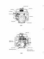
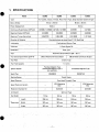
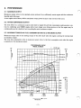
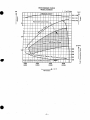
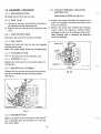
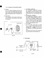
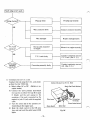
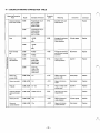
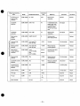
SERVICE
MANUAL
Models
EC06, EC08
1193s1 20
ROBIN AMERICA, INC.
ROBIN TO WISCONSIN ROBIN
ENGINE MODEL CROSS REFERENCE LIST
WISCONSIN ROBIN
ROBIN
0
SIDE VALVE
W 1-080
W1-145
W1-145V
W1-185
W1-185V
W1-230
W 1-280
W 1-340
W 1-390
Wl-45OV
EY21W
EY44W
EY18-3W
EY25W
EY27W
EY08
EY15
EY 15V
EY20
EY2OV
EY23
EY28
EY3 5
EY40 EY45V
EY2 1
EY44
EY 18-3
EY25
EY27
OVERHEAD VALVE
WO1-115
wo1-120
WO1-150
WO1-170
wo1-210
WOl-250
WO 1-300
WO1-300V
WO1-340
WO 1-340V
WO 1-43
OV
EH11
EH12
EH15
EH17
EH21
EH25
EH30
EH30V
EH34
EH34V
EH43V
0
TWO CYCLE
WT1-125V
EC13V
DIESEL
DY23
DY27
DY30
DY35
DY4 1
WRD 1-230
WRD 1-270
-1-300
WRD1-350
WRD1-410
0
CONTENTS
Section
1
.
Page
Title
2 . PERFORMANCE
4
.
1
................................................
2
Maximum Output . . . . . . . . : . . . . . . . . . . . . . . . . . . . . . . . . . . . . . . . . .
Rated
Continuous Output . . . . . . . . . . . . . . . . . . . . . . . . . . . . . . . . . . ; .
Maximum Torque and FuelConsumption Ratio a t Maximum Output . . . . . . . .
2-1
2-2
2-3
3.
..............................................
SPECIFICATIONS
FEATURES
....................................................
DISASSEMBLY and REASSEMBLY
4-1
4-2
4-3
4-4
.
..................................
Preparations
and
Suggestions
..................................
Special Tools . . . . . . . . . . . . . . . . . . . . . . . . . . . . . . . . . . . . . . . . . . . . .
Disassembly
Procedure
......................................
Reassembly
Procedure
.......................................
5. CONTACTBREAKERADJUSTINGPROCEDURE(EC06)
6.
CARBURETORADJUSTMENT
7. GOVERNORADJUSTMENT
.
8
TROUBLE-SHOOTING
8-1
8-2
8-3
8-4
8-5
8-6
8-7
9.
.
10
5
5
5
6
9
..................
13
.....................................
14
15
...........................................
16
Starting Trouble . . . . . . . . . . . . . . . . . . . . . . . . . . . . . . . . . . . . . . . . . . .
Idling Improper . . . . . . . . . . . . . . . . . . . . . . . . . . . . . . . . . . . . . . . . . . .
OverheatingandEngine
Knocking . . . . . . . . . . . . . . . . . . . . . . . . . . . . . . .
Power Drop : . . . . . . . . . . . . . . . . . . . . . . . . . . . . . . . . . . . . . . . . . . . . .
Excessive FuelConsumption . . . . . . . . . . . . . . . . . . . . . . . . . . . . . . . . . . .
Hunt.ing
Other Troubles . . . . . . . . . . . . . . . . . . . . . . . . . . . . . . . . . . . . . . . . . . . . . .
................................................
16
19
19
19
20
20
20
......................................
21
EngineStandard Correction Table . . . . . . . . . . . . . . . . . . . . . . . . . . . . . . .
Table of Tightening Torque . . . . . . . . . . . . . . . . . . . . . . . . . . . . . . . . . . .
22
24
.....................................
25
MAINTENANCE and STORING
10-1
10-2
10-3
10-4
10-5
4
.......................................
CHECKS and CORRECTIONS
9-1
9-2
2
2
2
Daily ChecksandMaintenance . . . . . . . . . . . . . . . . . . . . . . . . . . . . . . . . . .
Every 50 HoursChecksandMaintenance
:. . . . . . . . . . . . . . . . . . . . . . . . .
Every 150 HoursChecksandMaintenance
..........................
Yearly Checks
and
Maintenance
................................
Preparation for Long Abeyance . . . . . . . . . . . . . . . . . . . . . . . . . . . . . . . . .
25
25
25
25
25
Fuel Tank Cap
Recoil Starter
ECOGD
n
Spark Plug
Muffler Cover
overnor Lever
Engine Base (optional)
Governor Chamber
(Engine base is opti onal.)
ECOGB
ECOGD
Model
ECOGB
ECOID
ECO~B
Air-Cooled, 2-Cycle, Vertical, Piston Valve Type, Single Cylinder Gasoline Engine
Bore x Stroke
lacement
Piston
44mmx40mm
cc
78.5
Continuous Rated Output (HP/rpm)
I
I
50 mm x 40 mm
.
.60.8 cc
I
1.6/3600,1.9/4500 11.6/1440,
1.9/1800
Maximum Output (HP/rpm)
I
2.5/5000
. .
I
2.5/2000
1
1
2.2/4500
3.3/5500
2.2/1800
3-3/2200
~~
Maximum Torque (kg-m/rpm)
I
0.38/3700
Direction of Rotation .
.'
.
0.95/1480.
0.51/3600
Counterclockwise as viewed from P.T.O. Shaft Side
~
~~
Fuel-lubricant Mixture Type
Lubrication
~~
I
Lubricant
Carburetor'
.
I
2-Cycle Engine Oil
. .
_-
Float Type
Fuel
.
.
Gasoline-lubricant Mixture (20- 25: 1)
~
~~~
390 a t RatedContinuous Output380
Fuel Consumption Ratio (gr/HP-h)
Fuel Feed
1.5
1.27li440
at RatedContinuous Output
Gravity Type
Fuel Tank Capacity
iitres
L
.
~
Flywheel Magneto Type
(Contactless Magneto Type is
also available.)
Ignition System
.-
I
'Starting System
Starter
Speed Governor
NGKB7HS
Recoil
Centrifugal Flyweight Type
Speed Reduction System
Reduction Chamber Oil
Contactless Magneto Type
I
NGKB6HS
Spark Plug
~~
. .
-
1/2.5 Reduction
Gear
-
-
SAE #30
-
.Air Cleaner
.
1/2.5 Reduction
-
SAE#30.
Semi-wet Type
Dry Weight
I
Length
256 mm
285 mm
256 mm
285 mm
Width
307 mm
307 mm .
307 mm
307 mm'
Height
287 mm
287 mm
287 mm
287 mrn
"
Dimensions
2. PERFORMANCE
0
2-1 MAXIMUM OUTPUT
1
Maximum output refers to the standard power produced by a sufficiently run-in engine with the carburetor
throttle valve fully open.
A new engine cannot always deliver maximum output power because it has not been well run in.
2-2 RATEDCONTINUOUSOUTPUT
ri/
The term refers t o a continuous output most ideal to engine life and fuel consumption under governorcontrol. In combining your ROBIN engine with a load, design your driving system so that the engine may be
continuously used at a load level not exceeding the rated continuous output.
2-3 MAXIMUM TORQUE and FUEL CONSUMPTION RATIO a t MAXIMUM OUTPUT
Maximum torque refers to the driving torque of the drive shaft when the engine is driving the external load
at maximum output.
The term fuel consumption ratio at maximum output refers to the fuel consumption ratio when the engine
is operation at the maximum output.
PERFORMANCE CURVE
MODEL ECOGD/B
(
HP
1 for B type
I
w
2
P
+
6
(1 600)
(1 200)
W
--
Revolution
-2-
r.p.m.
(2000)
PERFORMANCE CURVE
MODEL EC08D/B
.
(
HP
)
for B type
kg-m
( 1.25)
W
(0.75)
gr/H P-h
(1600)
(1 200)
-*
(2000)
r.p.m.
Revolution
-3-
3. FEATURES
1. Compact, lightweight, high-powered enginewith reliable operation alsoin the low speed range
2. Extremely simple in construction, trouble-free, and veryeasy to use
(EC06)
3 . Quiet running engine using a lined aluminium cylinder
4. Equipped withT.C.I. (Transistor Circuit Ignition)
5 . So durable that theengine can stand hours of tough work.
Needle bearings are used for the crank pins and piston bearings t o enable the engine t o withstand highspeed operation underheavy load.
6. The carburetor works at inclinations of up t o aboaut 30" so that the engine can operate until the fuel
overflows from its air vent.
7 . The recoil starter permitseasy starting.
8. Useful in a wide rangeof applications
A direct-coupled, reduction type engine, and other types that differ from the standard models in drive
shaft dimensions and shape arealso available.
9. The all-speed governor operates at any engine speed.
The desired rpm. can be obtained by simply moving the control lever, and it remains constant even if
the load changes.
IO. Resistant to vibration (EC08)
Manufacturers of rammers and plates (machines for compacting earth by vibration) around the world
are using theseROBIN engines.
-4-
4. DISASSEMBLY and REASSEMBLY
4-1 PRE-PARATIONS and SUGGESTIONS
.Disassembly
.
.
.
-1) In"disassembling, remember the location of each part so that the disassembled partsEcan
be reassembled .
. .
in the right way. Attachtags to those parts which might be mistaken for others.
2) Carefully handle the gaskets because they can easily break.
3) Temporarily fasten disassembled parts in their original positionsto prevent them from missing and wrong
reassembly.
4) Carefully handle disassembled parts and clean them with kerosene.
5 ) Use thecorrect tools in the correct way.
6) Items necessary for disassembly and reassembly
. .
Disassembly
c.
tools
d. Kerosene or gasoline
'Work
a.
bench
b.
Kerosene pan
e. sandpaper, spatula,wastecloth
. .
7) Be sure to discharge the'fuel and oil before disassembling.
,
.
I
1
.
1
.Reassembly
m
1) Use new packing and gaskets in reassembling the engine.
2) Clean the parts with fresh gasoline, and blow them dry with compressed air before reassembling.
3) Apply 2-cycle oil to the rotary andsliding parts.
4) Keep the.parts free of dust during reassembly.
Tighten.the bolts, nuts, andscrews.with the specified torques.
5) Each'time a setof main parts is installed, manually'turn it and check for smoothness andnoise.'
6) After reassembling the engine, turn it manually and check for abnormalities and looseness. .
4-2 SPECIALTOOLS
.
. .
. %
"
..
Flywheel Pulley
Fig. 1
.
.
I
4-3-9 CONTACT BREAKER,CAPACITOR,
IGNITION COIL
4-3 DISASSEMBLY PROCEDURE
4-3-1 DISCHARGINGFUEL
[Point Type for EC06 (See
Fig.
Discharge the fuel from thefuel tank.
4-3-2FUEL TANK
1) Disconnect the pipe connecting the fuel filter to
the carburetor at the carburetor end.
2) Remove the fuel tank from the cylinder and fan
cover.
4-3-3 STOP BUTTON CORD
1) Remove the screws that fasten the capacitor and
point cover together, and remove the point cover
from the crankcase.
2) Remove the socket type terminal and mounting
screws,remove thecapacitor,contactbreaker,
and ignition coil from the crankcase in thisorder.
Note: Exercisecareinremovingthe
from the crankcase.
Disconnect the cord from the socketterminal.
3A.)]
grommet
4-3-4FAN COVER
Remove the bolts and then the
with the stop button.
fan cover together
Ignition Coil
Note: The rubber baffle comes off simultaneously.
4-3-5 CYLINDERCOVER
Remove the bolts and then the cylindercover.
4-3-6 STARTER PULLEY
Remove the bolts and then the starter
the flywheel.
pulley from
Point Cover
Breaker
4-3-7 MAGNETO and FLYWHEEL
Remove the nut and take the
flywheel from the front
end of the crankshaftusing the flywheel puller.
(See Fig. 2.)
Fig. 2
4-3-8 WOODRUFF KEY
Hold a screwdriver with its flat part on the woodruff
key, and lightly strike the screwdriver to remove the
key with a mallet.
-6-
Fig. 3A
n
\
/
[ T.C. I. (Transistor Control Ignition) magneto]
1) Features
The T.C.I. magneto completely solves the problems with the conventional point type magneto,
that is, stains, burns, rusting during long storage,
ignition timing deviation due
to mechanical wear,
etc.
2) Construction
The components of the magneto assembly are as
shown in Fig. 3B. The main parts of the magneto
are explained.
Flywheel Complete
./
T.C.I. Unit
FLYWHEEL COMPLETE
The FLYWHEEL COMPLETE haspermanent-magnets so that the rotation of these
magnets generates an AC electromotive force
in the primary coil of the generating assembly.
GENERATING ASSEMBLY
The GENERATING ASSEMBLY consists of
the primary coil and secondary coil. The rotation of the FLYWHEEL COMPLETE generates a voltage in the primary coil and feeds
a current. At the same time a high voltage is
induced in the secondary coil. Thishigh voltage causes the spark plug to spark.
T.C.I. UNIT
The T.C.I. UNIT consists maily of an SCR
and other semi-conductor parts. Itsenses the
primary current waveform generated in the
GENERATING ASSEMBLY, and switches
the transistor to cut off the primary coil current.
This abrupt currentchange causes a high voltage to be induced in the secondary
coil.
Generating Assembly
~
Fig. 3B
-
3) Wiring diagram
r
T.C.I. Unit
-7-
Prim r Wir
Spark Plug
*
Assembly
Fig. 3C
4-3- 10 CARBURETOR, GOVERNOR LEVER
4-3 - 13 REDUCTION GEAR (TypeB only)
1)Remove thenutandthenthecarburetorfrom
the cylinder.
2) Loosen the nut, and remove the governor lever
from the governor shaft.
3) Remove the governorspring from the governor
lever.
1) Remove the drain plug from the reductionchamber to discharge the oil.
2) Remove the reduction chamber cover from the
engine.
3) Remove the nuts, and pull the reduction pinion
out from the crankshaft.
(See Fig. 6.)
4) Remove the woodruff key.
c
Carburetor
eduction Chamber
Reduction Cover
Governor Lever
'Drain
%@" %
Reduction Pinion
Plug
Woodruff Key
L
n
Fig. 6
Fig. 4
\
4-3-1 1 SPARK PLUG
4-3-14CYLINDER
Remove the spark plug using a box wrench.
4-3- 12 MUFFLER (MUFFLER COVER)
Remove the nuts, and then the muffler from the
cylinder. (See Fig. 5 . )
Note: Keep the muffler cover on.
Nut
Remove the nuts, and carefully lift the cylinder off,
exercising care not to damage the contact surfaces
of the piston and cylinder.(See Fig. 7.)
Note: Hold the piston when the cylinder is lifted to
a certainheight from the crankcase, and raise the
cylinder off the piston. Damage to them can be prevented this way.
p/
Cylinder
Muffler Cover
rankcase
fig. 5
Fig. 7
-8-
4-3- 15 DIVIDING CRANKCASE
4-4 REASSEMBLY PROCEDURE
Remove the bolts, and carefully strike the crankcase
with a mallet t o part it. (See Fig.8.)
Clean the divided crankcase with gasoline, and apply
engine oil to the bearing, and grease to the oil seal
lips.
4-4-1 CRANKSHAFT COMPLETE and PISTON
Note: Be careful not to damage the crankcase joint.
Apply engine oilto theneedle bearing, and fitit onto
the small end of the connecting rod. With the mark
M on the piston head on the flywheel (magneto) side
fit the piston head on the piston. Apply
engine oil t o
the piston, and lightly strike the pin into the piston
with a mallet (until the pin is poisitoned inward of
the clip grooves). Then fit two clips into the clip
grooves. (See Fig. 10 .)
Note: Be careful n o t t odamage the piston pin hole
in the piston. Be sure to use new clips. The mark M
must be in the direction of the front end of the
crankshaft.
\
Rear Crankcase
I
Crankshaft
Fro"; Crankcase
Fig. 8
4-3- 16 PISTON, PISTON PIN, NEEDLE BEARING, and CLIPS (See Fig. 9.)
Remove the clips. With a iron rod 10 t o 1 1 mm in
diameter on the piston pin,
lightly strike it with a
plastic Hammer t o remove the piston pin. Pull out
the iron rod, andremove the piston andneedle bearing.
Fig. -10
.
I
4-4-2 INSERTINGCRANKSHAFTINTO
CRANKCASE
Note: Be careful not to damage the.piston pin hole
in the piston.
Place therear half of the crankcase on thework
bench securely, and insert the crankshaft into the
crankcase bearing by hand.
Note: See that the front
and rear halveso f the crankcase can be reassembled properly.
4-4-3 CRANKCASE REASSEMBLY (See Fig. 1 1.)
Wipe the joint surfaces of the front and rear halves
of the crankcase until oil is completelyremoved
from them, apply a sealant to them, and with the
dowels in line with their matching holes, reassemble
the crankcase.
Note: Exercisegood care not todamage the governor
sleeve, yoke assembly, and oil seals. Keep the joint
surfaces o f the front and rear halveso f the crankcase
parallel to each other in pressing them together into
the originalassembly.
-9-
I
Crankshaft
Rear Crankcase
\
Governor Yo1 ke
4-4-7 SPARK PLUG
Tighten the sparkplug into the cylinder.
Note: Tightening torque. . . . . . . 275 +25 kg-crn
4-4-8 GOVERNOR LEVER
Tighten the governor leverto thegovernor shaft with
the nut. (For the adjusting procedure, refer to the
section on governor adjustments.)
4-4-9 GOVERNORSPRING
I
E
Governors'
Front Crankcase
I
'
I
Hook the governor spring to the governor lever and
governor. (See Fig. 13.)
Note: Be careful of the hooking positions.
Fig. 1 1
4-4-4 CRANKCASE
Tighten the bolts with spring washers and
plain washers.
Note: Tightening torque . . . . . 1 10 f 20 kg-cm
.
4-4-5 CYLINDER REASSEMBLY (See Fig. 12.)
Replace the old cylinder gasket with a new one, apply oil to thecylinder and piston, make sure that the
piston rings and cylinder are positionedcorrectly,
and install thecylinder.
n
/
Governor Lever
Note: Be careful not to let the gasketslide out of
place.
Governor Spring
(attached to bottom)
Fig. 13
Cylinder
4-4- 10 CARBURETOR
Replace the old gasket with a new one, and install
the carburetor.
Note: Tightening torque . . . . . . . . 80 2 IO kg-cm
4-4- 11 MUFFLER (MUFFLER COVER)
Replace the old gasket with a new one, and tighten
the muffler to thecylinder.
Note: Tightening torque . . . . . . . . 80 f IO kg-cm
4-4- 12 WOODRUFF KEY
Drive the woodruff key into the keyway
in the crankshaft using a mallet.
Fig. 12
Note: Drive it parallel to the shaft axis.
4-4-6CYLINDER TIGHTENING
Tighten the nuts with springwashers and plain washers.
Note: Tigtening torque. . . . . . . . 1 10 k
Tighten all the four nuts evenly.
IO kg-crn
4-4- 13 IGNITION COIL TEMPORARY
TIGHTENING
With the high-tension cord (to be connected to the
spark plug) up, temporarily tighten the ignitioncoil.
- 10 -
n
4-4- 17 FLYWHEEL (MAGNETO)'
4-4- 14 CONTACT BREAKER (POINT)
CAPACITOR (EC06)
Installthecontact
breakerby inserting'itsshaftinto
the matching hole in the rcrankcase. Pass the cord
under the capacitor into the cord hole in the crankcase.
Temporarily tighten the capacitor.
4-4- 15 IGNITION TIMING CHECK (EC06)
Install the flywheel on the crankshaft by tightening
the nut'withplain and spring washers.
Note: Completely remove oil from the tapered portion.
Tightening torque . . . . . . . 400 k 20 kg-cm
4-4- 18 IGNITION COIL
Adjust the air gap with a searcher, and tighten the
ignition coil with plain and spring washers. (See Fig.
15.)
Temporarily install the flywheel, and check and adjust the ignition timing.
mm
(For ignition timing adjustment, refer to the section Note: Air gap. . . . . .0.5
on contact breaker adjusting procedure.)
Tightening torque .......... 50 f5kg-cm
foe.
Note: Ignition timing
4-4- 16POINT
............... 23" k2'
COVER (EC06)
,
,'
Remove the flywheel, fit the point-to-capacitor lead
into the crankcase groove, and install the.point cover. (See Fig. 14.)
Tighten the temporarily tightened capacitor
securely.
Note: Tightening torque . . . . . . . . . 25 f 2 kg-cm
Lead Wiring Method
Fig. 15
4-4-,19STARTER
Crankcase Groove
II
-./
I
/
Tighten the starter pulley to the flywheel with the
bolt. (Use plain and spring washers.)
Note: Tightening torque . . . . . . . . 90 f IO kg-cm
/
4-4-20 FANCOVER,STOP BUTTON,
GROMMET (See Figs. 16 and 17.)
Capacitor Lead
Primary Wire
Turn primarywire onceand
pull i t in direction A.
w
I
PULLEY
Install the stop button with lockwasher on the fan
cover.Insert the high-tensioncord into the grommet, and install baffle rubber on the fan cover. Fit
the grommet into thefan cover groove and, with the
tip of therubber baffle attheround boss in the
crankcase,fasten
the fan cover on the crankcase
with the bolt.
I
Capacitor lead is above
primary wire here.
Fig. 14
Note: Be careful not to pinch the stop button cord
between the crankcase and fan cover. Also exercise
care not to drop the rubber baffle during fan cover
reassembly.
Tightening torque . . . . . . . . 90 2 10 kg-cm
.
-11
-
L
4-4-21 CYLINDERCOVER
Insert the cylinder cover tips into thematching slots
in the crankcase, and tighten the cylinder cover on
the cylinder. (See Fig. 18.)
Note: Insert the cylinder cover tips in to the slots on
both sides.
Tightening torque . . . . . . . . 80 f 10 kg-cm
Cylinder Cover Installing Method
(Position in Model D l
Fig. 16
Buffle Rubber installing Method
Whichever type, D or B, your engine is, be careful of
the punched marks on the crankcase in reassembing.
Wider end up
Crankcase
Punched Mark (case)
Flat surface inside
Fig. 18
Baffle Rubber
4-4-22 FUEL TANK
Type D
Note: Install right of the magneto.
Insertthe fuelpipe intothecarburetor, clamp it,
and mount the fuel tank on the cylinder fan cover.
Note: Tightening torque . . . . . . . . 90 f 10 kg-cm
Wider end up
Punched Mark (case)
Flat surface inside
Baffle Rubber
,
Type
.Note: Install left of the magneto.
fig. 17
- 12
-
f7
, ’
5. CONTACT BREAKER ADJUSTING PROCEDURE (EC06)
1) Remove the fan cover.
2) Remove the starter pulley.
3) Remove the flywheel.
4) Loosen the capacitor screws.
5 ) Remove the point cover.
6) Remove carbon and other foreign particles from the point, polish-the contact surface with sandpaper
No.400 or equivalent, and wipe dirt off with a cloth.
7) Temporarily fasten the flywheel, bring the mark F in line with the matching mark on the crank case, and
remove the flywheel, exercising care not to turn it.
8) Now, in this state, adjust the contact breaker as shown below. (See Fig. 19.)
Mark
Fig. 19
Note: I f the points are open in the sate illustrated above, ignition timing goes wrong to a serious extent.
Be careful not to move the points especially when tigtenirig the breakermount screw.
Ignition timing . . . . . . . . . . . . . . . . . . . . .I.. . . . . . . 23" *2''
a ) . Loosen the breaker mounting screw.
b) Push the breaker in the arrow direction to a position just before the points begin to open (using a
timing tester, for example), and tighten'the breaker mounting screw.
c) After the point adjustment,install the point cover, capacitor, magneto, and fan cover in this order.
- 13 -
6. CARBURETORADJUSTMENT
n
The carburetor is carefuuly adjusted in the factory before shipment.Never attempt to adjust it except when
necessary.
1) Idling Adjustment (See Fig. 20.)
Move the governorlever to thelowest speedposition (so that the carburetor throttle valve fully
closes), and check that the engine idles quiet and
smooth. This is the ideal idling condition. Normally, the engine is set to anidling speed of 1600
k 100 rpm, for which thefollowing two methods
may be used.
a) Low-speed stopper screw
Engine speed increases if the low-speed stopper screw on the carburetor is turned clockwise, or decreases if it is turned counterclockwise.
b) Pilot screw (Do not turn it except
when necessary.)
When thepilot screw is turned clockwise,
the fuel-air mixture decreases and the engine
slows down. If the pilotscrew is turned counterclockwise, the fuel-air mixture increases
to raise engine speed. The normal positionof
the pilot screw is one turn anda quarter back
from the clockwise extremity.
Fig. 20
2) Maximum Speed Adjustment (See Fig. 2 1.)
The standard maximum speed is 5000 rpm for
EC06, or 5500 rpm for EC08.
Move the governor lever tothe highest speed
position,adjustthecrankshaftrpmto
5000
(EC06)or 5500 (EC08)withthe
high-speed
stopper bolt, and lock the bolt with the nut.
Governor Lever
Low Speed
Fig. 21
- 14 -
I
7. GOVERNOR ADJUSTMENT
Fully open the carburetor butterfly valve, fasten the
governor lever, turn the governor shaft fully counterclockwise, and fasten the governor lever on the governor shaft with the nut.(See Figs. 22 and,23.)
Fig. 22
Governor Rod
Governor Rod Spri
Throttle Lever
Carburetor
Governor Lever
Crankshaft
eed Stopper Bolt
Governor Sleev
Control Lever
Fig. 23
- 15 -
8. TROUBLE-SHOOTING
The following three conditions must be satisfiedfor satisfactory engine start:
1) The cylinder filled with a proper fuel-air mixture
2) An appropriate compression in the cylinder
3) Good spark at correct time to ignite mixture
The engine cannot be started unless these three conditions are met. There are also other factors which make
engine start difficult, e.g., a heavy load on the engine when it is about to start at low speed, and a high back
pressure due to a long exhaust pipe,just to say a few,
The most common causes of engine troubles aregiven below:
8-1 STARTING TROUBLE
Trouble
Cause
I
Remedy
Preventive hints
I
No or little
spark
Spark plug defective (1) If spark plug is dirty, clean it well with gasoline (1) Use a spark plug of the specified heat value. Do not use
or polish it with sand-paper. Remove foreign
low-quality oil. Clean the air
matter if any.
cleaner to prevent dust from
(2) Adjust spark gap to 0.6 0.7 mm.
entering.
(3) If spark plug hasfaulty instulation due to
(2) Be carefid not to strike the
breakage, replay it with anew one.
center pole or forcibly twist
it in adjusting spark gap.
Otherwise, insulation breaks
down.
-
High-tension cable
defective
If defective, replace the cable and ignition coil
together.
Contact breaker
defective
(1) If points are rough, polish them with sand-
paper No. 400.
(2) If point gap is wrong, loosen contact mount
screw, and adjust it to 0.35 ? 0.05 mm.
Also adjust ignition timing if possible.
(3) If ignition timing is wrong, adjust it to
23' f 2' before top dead center.
(4) If breaker has faulty insulation, replace
the breaker with a new one.
(5) If capacitor is defective, replace it with
a new one.
- 16 -
rrouble
Vo or little Magneto defective
;park
(1) If coil is broken or its insulation defective,
replace magneto with anew one.
(2) If magnetism has decreased, have it remagnetized at magneto manufacturer's or
replace magneto.with a new one.
~~
No or
little compression
No fuel
feed
~
~~
Electrical system
defective
(1) If stop button is defective (grounded),
repair or replace it.
(2) If primary wire is grounded to the engine
body, insulate it with tape.
Fuel leaks from
gaskets or other
(1) If head gasket is defective, replace it
with a new one.
(2) If spark plug is loose, retighten it securely.
(3) If spark plugis defective, replace it with
a new one.
Piston defective
(1) If piston is worn, replace it with a new one.
(2) If piston rings are worn, replace them
with new ones.
[ l ) Keep air cleaner clean.
:2) Do not use lowquality oil.
(3) Change oil periodically.
Fuel tank defective
(1) Clean tank outlet if clogged up.
(2) Clean fuel strainer if clogged up.
(3) If wrong fuel is used or if water is in fuel
tank, change fuel.
(4) If air is trapped in fuel pipe, discharge air.
(1) Pour fuel into the fuel tank
through filter.
(2) Use gasoline-oil (25 to 1)
mixture.
Carburetor
defective
(1) Clean carburetor if clogged up.
(2) Replace carburetor with anew one if
defective.
Clean jets and orifices if clogged up.
Excessive
fuel
suction
Excessive
resistance
to starting
Preventive hints
Remedy
Cause
'
(1) Fully open choke, half open throttle valve,
and start engine.
(2j Remove crankcase drain plug, close fuel cock,
actuate starter afew times to discharge
excess fuel.
Carburetor
defective
(1) If carburetor overflows, checkneedle
valve seat for wear, and replace if
necessary.
Excessive load
(1j Adjust power transmission belt tension
if too high.
(2) If it is still hard to start, install a clutch.
Piston or
connecting rod
sticky
(1) If piston is sticky, replace it with a new one.
(2) If connecting rod is sticky at large or
small end, replace it with anew one.
- 17 -
(1) Never close choke if engine
is warm.
(2) Be sure to idle engine for
some time before stoppingit.
This'not only makes next
.
starting easy but helps extend
engine life.
(3) Completely clean air cleaner
because a clogged up air
cleaner thickness fuel.
(1) Do not use lowquality oil.
(2) Use-fuel of correct gasolineoil ratio.
w
Spark plugs won't spark.
OK
Wire connector loose
Connect connectorsecurely.
Wire damaged
Replace damaged parts.
Not securely mounted
on engine
Mount it on engine securely.
L
-
~
-
i
OK
Conduct continuity test on
T.C.I. unit faulty
T.C.I.unit. [See 5 . I).]
r"\
\ I
Conduct continuity test on
coil. [See 5.2).]
Generating assembly faulty
1) Continuity test on T.C.I. unit
Conduct this testusing the T.C.I. unitchecker (Part No.106 79902 00).
Select either AC or DC. (Battery is installed inside.)
Connectthe unit'sprimary lead (black
for type D, or yellow for type B) to jack
E (black) andtheunit
casing (orthe
crankcase if the unit is mounted on the
engine) to jack C (red) with the supplied
cable.
Turn the select dial to the position correspoilding to the,engine type.
Keepthecheckswitch
in the ON position, and wait until the pilot lamp(LED)
lights.
- la
Robin Checker for T.C.I. Unit
Spark Gap Check Window
wer Select Switch
Check Switch
Select
Dial
Fig. 24
-
-
e) When the pilot lamp turns on, return the
check switch to the OFF position. The T.C.I. unit is
normal if a spark is observedat that instant.
If the T.C.I. unitchecker is not available, use a circuit tester as described below.
"i) Connect the positive (+) terminal of the tester to theprimary lead.
Connect the negative (-) terminal of the testerto the unitcasing.
Resistance: 80 to 150 ohms(Tester range x 1 ohm)
*ii) Connect the negative (-) terminal of the tester to the p$mary lead.
Connect the positive (+) terminal of the tester to the unitcasing.
Resistance: 7 t o 10 k oiims (Tester range x 100 ohms)
If the T.C.I. unit is found not normal by the above test, replace the unit.
2) Continuity test on generating assembly
Measure the resistance with a circuit tester.
a)Resistancebetweenprimarylead
andcore: 1.1 to 1.5 ohms
b) Resistance between secondary lead and core: 10 to 13 k ohms
If the generating assembly is found not normal by theabove test, replace the assembly.
Note: A circuit tester is not so accurate that the resistance values measured by the tester may vary depending on the type of tester, or the conditionof battery, or the skill of operator. '
0
8-2 IDLING IMPROPER
1) If the carburetor'spilot screw is notcorrectlyadjusted,adjustit.(Refer
adjustments.)
2) Any of starting trouble causes leads t o improper idling.
to the section oncarburetor
8-3 OVERHEATING and ENGINE KNOCKING
*
1 ) I f ignition timing is advanced, adjust it to 23" 2". (EC06)
2) I f the cmbustion chamber has excessive carbon deposits, clean it.
3) If a spark plug of a heat value too low is used, use one of the specified heat value. Example: NGK B6HS
for EC06, NGK B7HS for EC08
4) If the gasoline air-mixture is too lean, clean the jets and orifices of the carburetor. Also clean the aircleaner.
5) I f overload is the case, reduce it to normal level or below.
'
8-4 POWER DROP'
1 ) Replace the cylinder, piston, and/or piston rings if worn.
2) If the carburetor is faulty, adjust orclean it.
3) If the spark plug is faulty (dirty, leaky, or notproperly insulated), clean or replace it.
4) Retighten the cylinderif gas leaks.
5) Replace or adjust if the magneto or contact breaker is faulty.
6) Clean the air cleaner if clogged up.
7) Replace the crankshaft oil seals if compressed gas leaks due to seal wear.
-19-
8-5 EXCESSIVE FUELCONSUMPTION
1)
2)
3)
4)
If the gasoline-air mixture fuel is too rich, clean the carburetor jetsand orifices.
Replace the carburetor if its throttle shaft is worn.
Retighten or replace parts if fuel leaks.
Take the steps against power drop described in Paragraph 8-4above because excessive fuel consumption
also results from power drop.
8 - 6 HUNTING
1) If the governor lever, governor shaft, or governor spring is not properly set or adjusted, readjust or correct it.
2) If the mixture fuel is too lean, clean the carburetor.
3) If the carburetor pilotscrew is the cause, readjust it.
4) If the governor spring is worn, replace it.
5) If the governor sleeve does not work properly, correct it.
6) Replace the flyweight or governor sleeve if worn.
7) If the governor shaft does not work properly, correct it.
8-7 OTHERTROUBLES
1) Carburetor overflow
If the fuel overflows the carburetor to the air cleaner, or collects excessively in the crankcase during
stoppage, either the floatvalve or float is faulty. Replace or correct the faultyone.
2) If the engine abruptlystops with an abnormalnoise,it is dueto a stickypiston,crankshaft, or connecting rod. Adjust or replace the faulty parts.
3) If any abnormal noise is heard during engine operation, be sure to stop the engine immediately. Do not
start the engine again until the cause is determined.
If you cannot find the cause, contact your nearest dealer or service shop, and observe their advice.
- 20 -
f"\/
..
._ .
..
.
..
.
. .
...
. .
...
.
. .
.
.
.
"
.
,
,
.
,.
.
,
I
8
%
I
.
.
I
.j
,
.
... .
.. .
. -
,
. . .
-
.
,
'9. CHECKS and CORRECTIONS
~-
-
:' 0 .
.
-.
'
"
.
I
.
.
.
.
After disassembiing and cleaning the'engine, check and adjust the parts according to the Standard Correction
. ;Table, .-whichprovides importantinformationto
bereferred to in adjusting or repairing the engine. Be
. ;.fWiliar-with the table and conform to the.standards
specifiedin servicing the engine.
The terms used in the table aredefined as follows:
.
1) - Correction .
Repair, adjustment,or replacement of any engine part
.2) Correctionlimit
The limit of wear, damage, or function degradation beyond which an engine part can hardly
serve its
purpose unless if is corrected.
. 3) Standard dimensions
Design dimensions less tolerance
.
'
:
.
.
-21
-
9-1 ENGINE STANDARD CORRECTION TABLE
I
Measuring/Correcting
Point
Clearance between
piston and cylinder
Bore
T
Model
Standard Dimensions
EC06
Perpendicular t o pin
0.07-0.1 06L
Pin direction
0.09-0.146L
EC08
Perpendicular to pin
0.04-0.076 L
Pin direction
0.07-0.1 26L
EC06
tO.016
Correction
Limit
Instrument
Correction
0.18L
Calculate from parts
measurements.
+0.08
Average of maximum
and minimum
inside diameters
Cylinder gauge
Replace
-0.05
Average of maximum
and minimum outside
diameters
Micrometer
Replace
0.1 5L
Measure after
removing carbon.
Searcher
Replace
0
44@
EC08
/
Measuring
Replace
M.016
0
5w
Piston outside
dia.
Piston ring
side clearance
EC06
43.930
EC08
49.960
EC06
First ring
0.05-0.09L
Second ring
0.04-0.08L
EC08
First ring
0.06-0.1OL
Second ring
0.03-0.07L
Piston ring
groove width
EC06, EC08
1.8
4-0.13
Measure maximum
groove width.
Block gauge
Replace
Piston ring width
E m , EC08
1.8
-0.10
Measure minimum
Lvidrh.
Micrometer
Replace
Ring gap
EC06, EC08
0.1-0.3
1.o
Ring in contact with
cylinder wall
Searcher
Replace
Clearance between
piston and piston
pin
EC06, EC08
0.005T-0.014L
0.03L
Calculate from parts
measurements
Piston pin hole
EC06, EC08
M.03
Measure maximum
inside diameter
Piston pin
outside diameter
EC06, EC08
-0.017
~~
- 22 -
Replace
Cylinder gauge
Replace
Micrometer
Replace
~~
Measure minimum
outside diameter.
I
MeasuringlCorrecting
Point
Model
Standard Dimensions
Correction
Limit
0.1 -0.6L
0.8 L
Measure after
reassembly
Searcher
Measuring
instrument
Correction
Connecting r o d
large end side
clearance
EC06, EC08
Crankshaft
deviation
EC06. EC08
0.05 or less
0.1
in reassembled state,
support both ends
of crankshaft, and
measure it about
7.5 mm from crank
web.
Dial gauge
Crankshaft
axial play
EC06, EC08
0.1 5-0.69
0.1
Measure after
reassembly.
Dial gauge
Main bearing
outside
diameter
EC06, EC08
0.050T-0.01.4T
0
Calculate from
parts measurements
Housing inside
diameter
EC06, EC08
Front case 47@
Rear case 420
-0.04
Housing
Cylinder gauge
Replace
Bearing outside
diameter
EC06, EC08
Front case 470
Rear case 420
-0.016
Measure bearing
outside diameter
Micrometer
Replace
Main bearing
outside diameter
clearance
EC06, EC08
Front
0.013T-0.006L
Rear
0.01 T-0.009L
0.01 2 L
Calculate from parts
measurements.
Bearing inside
diameter
EC06, EC08
20@
M.005
Measure bearing
inside diameter.
Cylinder gauge
Replace
Crankshaft outside
diameter
EC06, EC08
-0.02
Measure crankshaft
outside diameter
Micrometer
Replace
Connecting r o d
small end inside
diameter
EC06, EC08
+0.026
Cylinder gauge
Replace
~
Replace
Replace
Replace
0.01 5L
~
Ignition timing
EC06
23'
f 2O
Timing tester
Adjust
Point gap
EC06
0.35
* 0.05
Searcher
Adjust
Air gap
EC06
0.5
Searcher
Adjust
Searcher
Adjust
0
-0.1
0.6-0.7
- 23 -
9 - 2 TABLE of TIGHTENING TORQUE
Parts to tighten
No.
Tightening torque
Screw
diameter
Remarks
kgcm
1
Cylinder Cover, Muffler Cover
80*10
M6
5T
2
Fan Cover, Tank Support Plate,
Starter, Starter Pulley
90k10
M6
5T
3
Crankcase
110 -+20
M6
7T
4
Air Cleaner
50 +5
M5
5T
5
Reduction Cover
110+20
M6
7T
6
Muffler
80+10
7
Cylinder
110+10
M6
7T
Nut
8
Carburetor
80 + l o
M6
4T
Nut
9
Governor Yoke
18 *2
M3
4T
10
Governor Plate
5025
M5
4T
11
Ignition coil
50 *5
M5
4T
12
Contact Breaker, Condensor
Point Cover
25 +2
M4
4T
13
Reduction Pinion
340 220
M I 2 4T
14
Spark Plug
275 *25
MI4
15
Magneto Flywheel
400 + 20
M106T
16
Governor Lever
80*10
M6
4T
17
Stop Button
40 +5
M4
4T
18
Rear Half of Crankcase
.
M6
Nut
M6
(Stand)
-
Note: Be careful not to apply screw lock more than necessary.
- 24 -
Type B only
Apply screw lock (FT15 or equivalent)
and install (as in the case of EC05, EC07)
Nut, Type B only
Apply screw lock (FT15 or equivalent)
and install (as in the case of EC05, EC07)
10. MAINTENANCE and STORING
0
. .
,
The following maintenance jobs apply when the engine
is operated correctly under normal conditions. The
indicated maintenance intervals are by no means guarantees- for maintenance free operations during these
intervals. For example, if the engine is operated in extremely dusty conditions, the air cleaner should be
cleaned every day, instead of every 50 hours.
.10-1 DAILY CHECKS and.MAINTENANCE
1) Remove just from whatever which accumulated dust.
2) Check external fuel leakage. If any, retighten or replace.
3) Check screw tightening. If any lose one is found, retighten.
4) Clean air cleaner.
10-2 EVERY 50 HOURS CHECKS and MAINTENANCE
Check spark plug. If contaminated, wash in gasoline or polish with emery paper.
10-3- EVERY 150 HOURS CHECKS and MAINTENANCE
0
1) Clean fuel straine-r and fuel tank.
2) Clean contact breaker points.
3) Clean exhaust port ofcylinder and both inletand outlet of muffler.
10-4 YEARLY CHECKS and MAINTENANCE
..
1) Remove carbon from cylinder head and piston head.
2) Clean fuel tank inside.
3) Clean carburetor float chamber inside.
4) Clean contact breaker and adjust point gap.
5) Replace fuel pipe once a year.
10-5 PREPARATION for LONG ABEYANCE
1) Perform the above 10- 1 and 10-2 maintenance jobs.
2) Drain fuel from the fuel tank and carburetor float chamber.
3) Remove spark plug, and apply 5 to 10 cc of lubricating oil through the spark plug hole. Perform idle
operation several times by pulling the recoil starter handleslowly. Re-install the spark plug.
4) Clean the engine outsidewith oiled cloth.
5) Put a vinyl or other cover over the engine and store the engine in dry place.
I
.'
-
.
L
.
.
. . .
- 25 -
Industrial
Engines