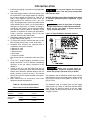
1
(S) LPRFM-5R
J30-05377C
INSTALLATION INSTRUCTIONS AND PARTS LIST
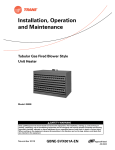
TUBULAR GAS FIRED PROPELLER UNIT HEATERS
– FOR RESIDENTIAL INSTALLATIONS –
ATTENTION: READ THIS MANUAL AND ALL LABELS ATTACHED TO THE UNIT CAREFULLY BEFORE
ATTEMPTING TO INSTALL, OPERATE OR SERVICE THESE UNITS! CHECK UNIT DATA PLATE FOR TYPE OF GAS AND
ELECTRICAL SPECIFICATIONS AND MAKE CERTAIN THAT THESE AGREE WITH THOSE AT THE POINT OF INSTALLATION.
RECORD THE UNIT MODEL AND SERIAL No.(s) IN THE SPACE PROVIDED. RETAIN FOR FUTURE REFERENCE.
Model No.
Serial No.
FOR YOUR SAFETY
Do not store or use gasoline or other flammable vapors and liquids in the vicinity of this or
any other appliance.
FOR YOUR SAFETY
WHAT TO DO IF YOU SMELL GAS
Do not try to light any appliance.
Do not touch any electrical switch; do
not use any phone in your building.
Immediately call your gas supplier
from a neighbor’s phone. Follow the
gas supplier’s instructions.
If you cannot reach your gas supplier,
call your fire department.
Improper installation, adjustment, alteration, service, or maintenance can
cause property damage, injury, or death. Read the installation, operating, and
maintenance instruction thoroughly before installing or servicing this equipment.
APPROVED FOR USE IN CALIFORNIA
Install, operate, and maintain unit in accordance with the manufacturer's
instructions to avoid exposure to fuel substances, or substances from incomplete combustion,
which can cause death or serious illness. The state of California has determined that these
substances may cause cancer, birth defects, or other reproductive harm.
INSTALLER'S RESPONSIBILITY
Installer Please Note: This equipment has been test fired and inspected. It has been
shipped free from defects from our factory. However, shipment and installation
problems such as loose wires, leaks, or loose fasteners may occur. It is the installer's
responsibility to inspect and correct any problem that may be found.
RECEIVING INSTRUCTIONS
Inspect shipment immediately when
received to determine if any damage has
occurred to the unit during shipment. After
the unit has been uncrated, check for any
visible damage to the unit. If any damage
is found, the consignee should sign the bill
of lading indicating such damage and
immediately file claim for damage with the
transportation company.
09/04
HVAC PRODUCTS
260 NORTH ELM ST., WESTFIELD, MA 01085
TEL: (413) 564-5540 FAX: (413) 562-5311
http://www.mestek.com
MODELS: RF-30, 45, 60, 75, 90
Please utilize this toll free number to contact your local
representative 800-490-2290.
TABLE OF CONTENTS
SPECIFICATIONS
Basic Description .................................................... 2
Performance & Specification Data .......................... 4
GENERAL SAFETY INFORMATION
Installation Codes ................................................ 2, 3
Special Precautions ............................................ 2, 3
INSTALLATION
Locating Units ..................................................... 5, 6
Combustion Air .................................................... 5, 6
Proper Clearances .............................................. 5, 6
Suspension of Units ............................................ 5, 6
Gas Supply Piping ............................................... 7, 8
ELECTRICAL CONNECTIONS ................. 9, 10, 11, 12
VENTING ........................................... 13, 14, 15, 16, 17
OPERATION
Explanation of Controls and Operation ................. 18
Main Burner Orifice Schedule ............................... 19
Adjustments .......................................................... 19
High Altitude Operation ................................... 19, 20
MAINTENANCE
Servicing & Cleaning ............................................. 20
TROUBLESHOOTING GUIDE ................. 21, 22, 23, 24
IDENTIFICATION OF PARTS .............................. 25, 26
WARRANTY ............................................................... 27
INSPECTION SHEET ................................................ 28
NOTICE: It is the equipment owners responsibility to provide any scaffolding or other apparatus required to
perform emergency service or annual/periodic maintenance to this equipment.
DESCRIPTION
CSA . 10.96 U.S. (2nd ed.) “Unit Heaters for Residential
Installation”. The designs are certified by CSA
International as providing a minimum of 80% thermal
efficiency, and approved for use in California. Do not
alter these units in any way. If you have any questions
after reading this manual, contact the manufacturer.
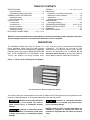
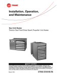
The Residential Tubular Gas Fired Unit Heater is a
factory assembled, power vented, low static pressure
type propeller fan unit heater designed to be suspended
within the space to be heated. THESE HEATERS ARE
NOT TO BE CONNECTED TO DUCTWORK. These
Tubular Unit Heaters are design certified under
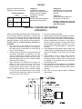
Figure 1 - Tubular 30 thru 90 Propeller Unit Heaters
See Identification of Parts throughout this manual.
The following terms are used throughout this manual, in addition to the CSA requirements to bring attention to the
presence of potential hazards, or to important information concerning the product:
Indicates an imminently hazardous
situation which, if not avoided, will result in
death, serious injury, or substantial property
damage.
Indicates an imminently hazardous situation which, if not avoided, could result
in death, serious injury, or substantial property
damage.
Indicates an imminently hazardous
situation which, if not avoided, may result in minor
injury or property damage.
NOTICE: Used to notify of special instructions on
installation, operation, or maintenance which are
important to equipment but not related to personal
injury.
2
GENERAL SAFETY INFORMATION
Failure to comply with the general
safety information may result in extensive
property damage, severe personal injury, or
death.
Do not attempt to convert the
heater for use with a fuel other than the one
intended. Such conversion is dangerous, as it
will create the risks previously listed.
This product must be installed by
a licensed plumber or gas fitter when installed
within the Commonwealth of Massachusetts.
Make certain that the power source conforms to the
electrical requirements of the heater.
Do not depend upon a thermostat
or other switch as sole means of disconnecting
power when installing or servicing heater. Always
disconnect power at main circuit breaker as
described above. Failure to do so could result in
fatal electric shock.
Installation must be made in accordance with local
codes, or in absence of local codes, with ANSI
Standard Z223.1-2002. (N.F.P.A. No. 54) National Fuel
Gas Code, or the latest edition of. All of the ANSI and
NFPA Standards referred to in these installation
instructions are those that were applicable at the time
the design of this appliance was certified. The ANSI
Standards are available from the American Gas
Association, 1515 Wilson Boulevard, Arlington, Virginia
22209. The NFPA Standards are available from the
National Fire Protection Association, Batterymarch Park,
Quincy, MA 02269.
Special attention must be given to any grounding
information pertaining to this heater. To prevent the risk
of electrocution, the heater must be securely and
adequately grounded. This should be accomplished by
connecting a ground conductor between the service panel
and the heater. To ensure a proper ground, the grounding
means must be tested by a qualified electrician.
If installed in Canada, the installation must conform with
local building codes, or in the absence of local building
codes, with CGA-B149.1 "Installation Codes for Natural
Gas Burning Appliances and Equipment" or CGA-B149.2
"Installation Codes for Propane Gas Burning Appliances
and Equipment." These unit heaters have been designed
and certified to comply with CGA 2.6.
Do not insert fingers or foreign objects into heater or its
air moving device. Do not block or tamper with the heater
in any manner while in operation, or just after it has been
turned off, as some parts maybe hot enough to cause
injury.
This heater is intended for general heating applications
ONLY. It must NOT be used in potentially dangerous
locations such as flammable, explosive, chemical-laden,
or wet atmospheres.
Do not alter the unit heater in any
way or damage to the unit and/or severe personal
injury or death may occur!
Do not attach ductwork to this product or use it as a
makeup air heater. Such usage voids the warranty and
will create unsafe operation.
Disconnect all power and gas
supplies before installing or servicing the heater.
If the power disconnect is out of sight, lock it in
the open position and tag it to prevent unexpected
application of power. Failure to do so could result
in fatal electric shock, or severe personal injury.
In cases in which property damage may result from
malfunction of the heater, a back-up system or
temperature sensitive alarm should be used.
Insure that all power sources conform
to the requirements of the unit heater, or damage to
the unit will result!
The open end of piping systems being
purged shall not discharge into areas where there
are sources of ignition or into confined spaces
UNLESS precautions are taken as follows: (1) by
ventilation of the space, (2) control of the purging
rate, (3) elimination of all hazardous conditions. All
precautions must be taken to perform this operation
in a safe manner!
Follow installation instructions CAREFULLY to avoid
creating unsafe conditions. All wiring should be done
and checked by a qualified electrician, using copper wire
only. All gas connections should be made and leaktested by a suitably qualified individual, per instructions
in this manual. Also follow procedures listed on "Gas
Equipment Start-Up Sheet" located in this manual.
Unless otherwise specified, the following conversions
may be used for calculating SI unit measurements:
1000 BTU/cu. ft. = 37.5 MJ/m3
1 foot = 0.305 m
1000 BTU per hour = 0.293 kW
1 inch = 25.4 mm
1 inch water column = 0.249 kPa
1 gallon = 3.785 L
1 pound = 0.453 kg liter/second = CFM x 0.472
1 psig = 6.894 kPa meters/second = FPM ÷ 196.8
1 cubic foot = 0.028m3
Use only the fuel for which the heater is designed (see
rating plate). Using LP gas in a heater that requires
natural gas, or vice versa, will create risk of gas leaks,
carbon monoxide poisoning, and explosion.
3
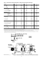
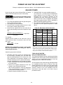
Table 1 - Performance and Dimensional Data - Tubular 30 thru 90 Propeller Unit Heater
Unit Size
PERFORMANCE DATA†
Input - BTU/Hr.
(kW)
Output - BTU/Hr.
(kW)
Thermal Efficiency (%)
Free Air Delivery - CFM
(cu. m/s)
Air Temperature Rise - Deg. F
(Deg. C)
Full Load Amps at 120V **
MOTOR DATA: Motor HP
Motor (kW)
Motor Type
R.P.M.
Motor Amps @ 115V
DIMENSIONAL DATA - inches (mm)
“A” Jacket Height
“B” Overall Height
“C” Overall Depth
“Center Line” Height of Flue*
“Center Line” Electric Connection
“F” Discharge Opening Height
“G” Fan Diameter-in
Unit Weight - lbs.
(kgs)
Shipping Weight - lbs.
(kgs)
30
45
60
75
90
30,000
(8.8)
24,300
(7.1)
81
500
(0.236)
45
(25)
3.0
1/20
(0.37)
SP
1650
1.9
45,000
(13.2)
36,450
(10.7)
81
750
(0.355)
45
(25)
3.0
1/20
(0.37)
SP
1650
1.9
60,000
(17.6)
48,600
(14.2)
81
1,000
(0.473)
45
(25)
3.7
1/20
(0.37)
SP
1050
2.6
75,000
(22.0)
60,750
(17.8)
81
1,250
(0.591)
45
(25)
3.7
1/20
(0.37)
SP
1050
2.6
90,000
(26.4)
72,900
(21.4)
81
1,500
(0.710)
45
(25)
4.8
1/20
(0.37)
SP
1050
2.6
12
(305)
13
(330)
25-1/2
(648)
7-1/4
(184)
10-1/4
(260)
10-1/2
(267)
10
62
(28)
72
(33)
12
(305)
13
(330)
25-1/2
(648)
7-1/4
(184)
10-1/4
(260)
10-1/2
(267)
10
68
(31)
78
(35)
17-3/4
(451)
18-3/4
(476)
26-3/4
(679)
10-1/2
(267)
16
(406)
16-1/4
(413)
16
87
(39)
102
(46)
17-3/4
(451)
18-3/4
(476)
26-3/4
(679)
10-1/2
(267)
16
(406)
16-1/4
(413)
16
93
(42)
108
(49)
17-3/4
(451)
18-3/4
(476)
26-3/4
(679)
10-1/2
(267)
16
(406)
16-1/4
(413)
16
95
(43)
110
(50)
* Canadian unit includes the vent cap.
* For all installations, the flue collar is included with the unit and should be field installed per the instructions included with the unit.
† Ratings shown are for unit installations at elevations between 0 and 2,000 ft (0 to 610m). For unit installations in U.S.A. above 2,000 ft. (610m), the unit input must be derated 4% for each 1,000 ft. (305m) above sea
level; refer to local codes, or in absence of local codes, refer to the National Fuel Gas Code, ANSI Standard Z223.1-2002 (N.F.P.A. No. 54), or the latest edition (also refer to Table 4).
For installations in Canada, any reference to deration at altitudes in excess of 2,000 ft. (610m) are to be ignored. At altitudes of 2,000 ft. to 4,500 ft. (610 to 1372m), the unit must be derated to 90% of the normal
altitude rating, and be so marked in accordance with the CSA certification.
DIMENSIONS .XXX STANDARD UNITS
DIMENSIONS IN PARENTHESIS (XXX) MILLIMETERS
Figure 2 - Dimensional Drawing – Tubular 30 thru 90 Propeller Unit Heater
4
INSTALLATION
Do not install unit heaters in
corrosive or flammable atmospheres! Premature
failure of, or severe damage to the unit will
result!
AIR FOR COMBUSTION: The unit heater shall be
installed in a location in which the facilities for ventilation
permit satisfactory combustion of gas, proper venting,
and the maintenance of ambient air at safe limits under
normal conditions of use. The unit heater shall be located
in such a manner as not to interfere with proper
circulation of air within the confined space. When
buildings are so tight that normal infiltration does not
meet air requirements, outside air shall be introduced
per Sections 1.3.4.2 and 1.3.4.3 of ANSI Z223.1 for
combustion requirements. A permanent opening or
openings having a total free area of not less than one
square inch per 5,000 BTU/Hr (1.5 kW) of total input
rating of all appliances within the space shall be
provided.
Avoid locations where extreme
drafts can affect burner operation. Unit heaters
must not be installed in locations where air for
combustion would contain chlorinated,
halogenated or acidic vapors. If located in such
an environment, premature failure of the unit
will occur!
Since the unit is equipped with an automatic gas ignition
system, the unit heater must be installed such that the
gas ignition control system is not directly exposed to
water spray, rain or dripping water.
NOTICE: Unit Heater sizing should be based on heat
loss calculations where the unit heater output equals
or exceeds heat loss.
NOTICE: Location of unit heaters is related directly
to the selection of sizes. Basic rules are as follows:
CLEARANCES: Each Gas Unit Heater shall be located
with respect to building construction and other equipment
so as to permit access to the Unit Heater. Clearance
between vertical walls and the vertical sides of the Unit
Heater shall be no less than 1 inch (25.4mm). However,
to ensure access to the control box and fan, a minimum
of 18" (457mm) is required for the fan, and control box
side. A minimum clearance of 1 inch (25.4mm) must be
maintained between the top of the Unit Heater and the
ceiling. The bottom of the Unit Heater must be no less
than 1 inch (25.4mm) from any combustible. The
distance between the flue collector and any combustible
must be no less than 1 inch (25.4mm). Also see AIR
FOR COMBUSTION and VENTING sections.
MOUNTING HEIGHT: If the unit heater is installed in a
garage, it must be installed with a minimum clearance
above the floor of 18 inches (457mm).
AIR DISTRIBUTION: Direct air towards areas of
maximum heat loss. When multiple heaters are involved,
circulation of air around the perimeter is recommended
where heated air flows along exposed walls. Satisfactory
results can also be obtained where multiple heaters are
located toward the center of the area with heated air
directed toward the outside walls. Be careful to avoid
all obstacles and obstructions which could impede the
warm air distribution patterns.
Unit heaters should not be installed to maintain low
temperatures and/or freeze protection of buildings.
A minimum of 50°F (10°C) thermostat setting must
be maintained. If unit heaters are operated to maintain
lower than 50°F (10°C), hot flue gases are cooled inside
the heat exchanger to a point where water vapor (a flue
gas by-product) condenses onto the heat exchanger
walls. The result is a mildly corrosive acid that
prematurely corrodes the aluminized heat exchanger
and can actually drip water down from the unit heater
onto floor surface. Additional unit heaters should be
installed if a minimum 50°F (10°C) thermostat setting
cannot be maintained.
NOTICE: Increasing the clearance distances may
be necessary if there is a possibility of distortion or
discoloration of adjacent materials.
MOUNTING: The Unit Heater may be mounted with the
vent outlet, gas and electrical connections to the right
or left of the air moving fan. The Unit Heater is shipped
with the connections to the right of the fan when looking
in the direction of the air flow. If connections to the right
are required, remove the (4) screws from the front top
edge and the (5) screws from the rear top edge of the
heater. Mount the hanging brackets (shipped loose in
bottom of the carton) using the removed screws. If
connections to the left are required, invert the heater
(180°), mount the hanging brackets as above, and
remove, invert, and replace the control access panel
and the air discharge louvers.
5
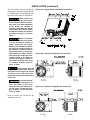
INSTALLATION (continued)
The Unit Heater may be mounted by
fastening the hanging brackets directly
to ceiling joists or by suspending from
four rods. See Figures 3A, 3B and 3C.
Figures 3A - Hanger Bracket Installation Instructions
Make certain that
the lifting methods used to lift the
heater and the method of suspension used in the field installation
of the heater are capable of
uniformly supporting the weight
of the heater at all times. Failure
to heed this warning may result in
property damage or personal
injury!
Make sure that the
structure to which the unit heater
is to be mounted is capable of
safely supporting its weight.
Under no circumstances must the
gas lines, the venting system or
the electrical conduit be used to
support the heater; or should any
other objects (i.e. ladder, person)
lean against the heater gas lines,
venting system or the electrical
conduit for support. Failure to
heed these warnings may result
in property damage, personal
injury, or death.
Figures 3B - Heater Mounting (Steel Construction)
Unit Heaters must be
hung level from side to side and from
front to back, see Figures 3A, 3B and
3C. Failure to do so will result in poor
performance and/or premature failure
of the unit.
Insure that all hardware used in the suspension of
each unit heater is more than
adequate for the job. Failure to do
so may result in extensive property damage, severe personal
injury, or death!
Figures 3C - Heater Mounting (Wood Construction)
Refer to Figures 3A, 3B and 3C for
suspension of units.
6
GAS PIPING
To avoid damage or possible personal injury, do not connect gas piping to this unit
until a supply line pressure/leak test has been completed. Connecting the unit before completing the
pressure/leak test may damage the unit gas valve and result in a fire hazard.
Do not rely on a shut-off valve to isolate the unit while conducting gas pressure/leak tests. These
valves may not be completely shut off, exposing the gas valve to excessive pressure and damage.
PIPE SIZING
To provide adequate gas pressure to the gas unit heater,
size the gas piping as follows:
NOTICE: If more than one unit heater is to be served
by the same piping arrangement, the total cu. ft./hr.
input and length of pipe must be considered.
1. Find the cu. ft./hr. by using the following formula:
Input
Cu. ft./hr. =
BTU
2. Refer to Table 2. Match “Length of Pipe in Feet”
with appropriate “Gas Input - Cu. Ft./Hr.” figure.
This figure can then be matched to the pipe size at
the top of the column.
Example:
It is determined that a 67 foot (20.4m) run of gas
pipe is required to connect a 75 MBTU gas unit
heater to a 1,000 BTU/cu ft. (0.29kW) natural gas
supply.
75,000 BTU/Hr
= 75 Cu. ft./hr.
1,000 BTU/cu. ft.
Using Table 2, a 3/4 inch pipe is needed.
NOTICE: If the gas unit heater is to be fired with LP
gas, consult your local LP gas dealer for pipe size
information.
HEATER INSTALLATION FOR USE WITH PROPANE
(BOTTLED) GAS MUST BE MADE BY A QUALIFIED
L.P. GAS DEALER OR INSTALLER. HE WILL ENSURE
THAT PROPER JOINT COMPOUNDS ARE USED FOR
MAKING PIPE CONNECTIONS; THAT AIR IS PURGED
FROM LINES; THAT A THOROUGH TEST IS MADE
FOR LEAKS BEFORE OPERATING THE HEATER;
AND THAT IT IS PROPERLY CONNECTED TO THE
PROPANE GAS SUPPLY SYSTEM.
Before any connection is made to the existing line
supplying other gas appliances, contact the local gas
company to make sure that the existing line is of
adequate size to handle the combined load.
NOTE: See General Safety Information section for
English/Metric unit conversion factors.
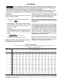
Table 2 - Gas Pipe Size
Maximum Capacity of Pipe in Cubic Feet of Gas per Hour (Cubic Meters per Hour) for Gas Pressures of 0.5 psig (3.5 kPa) or Less,
and a Pressure Drop of 0.5 Inch Water Column (124.4 Pa)
(Based on a 0.60 Specific Gravity Gas)
Nominal
Iron
Internal
Pipe Size
Dia.
in.
1/2
in.
0.622
3/4
0.824
1
1.049
1 1/4
1.380
1 1/2
1.610
2
2.067
2 1/2
2.469
3
3.068
4
4.026
Length of Pipe, Feet (meters)
10
(3.0)
175
(4.96)
360
(10.2)
680
(19.3)
1400
(39.6)
2100
(59.5)
3950
(112)
6300
(178)
11000
(311)
23000
(651)
20
(6.1)
120
(3.40)
250
(7.08)
465
(13.2)
950
(26.9)
1460
(41.3)
2750
(77.9)
4350
(123)
7700
(218)
15800
(447)
30
(9.1)
97
(2.75)
200
(5.66)
375
(10.6)
770
(21.8)
1180
(33.4)
2200
(62.3)
3520
(99.7)
6250
(177)
12800
(362)
40
(12.2)
82
(2.32)
170
(4.81)
320
(9.06)
660
(18.7)
990
(28.0)
1900
(53.8)
3000
(85.0)
5300
(150)
10900
(309)
50
(15.2)
73
(2.07)
151
(4.28)
285
(8.07)
580
(16.4)
900
(25.5)
1680
(47.6)
2650
(75.0)
4750
(135)
9700
(275)
60
(18.3)
66
(1.87)
138
(3.91)
260
(7.36)
530
(15.0)
810
(22.9)
1520
(43.0)
2400
(68.0)
4300
(122)
8800
(249)
70
(21.3)
61
(1.73)
125
(3.54)
240
(6.80)
490
(13.9)
750
(21.2)
1400
(39.6)
2250
(63.7)
3900
(110)
8100
(229)
80
(24.4)
57
(1.61)
118
(3.34)
220
(6.23)
460
(13.0)
690
(19.5)
1300
(36.8)
2050
(58.0)
3700
(105)
7500
(212)
90
(27.4)
53
(1.50)
110
(3.11)
205
(5.80)
430
(12.2)
650
(18.4)
1220
(34.5)
1950
(55.2)
3450
(97.7)
7200
(204)
100
(30.5)
50
(1.42)
103
(2.92)
195
(5.52)
400
(11.3)
620
(17.6)
1150
(32.6)
1850
(52.4)
3250
(92.0)
6700
(190)
125
(38.1)
44
(1.25)
93
(2.63)
175
(4.96)
360
(10.2)
550
(15.6)
1020
(28.9)
1650
(46.7)
2950
(83.5)
6000
(170)
150
(45.7)
40
(1.13)
84
(2.38)
160
(4.53)
325
(9.20)
500
(14.2)
950
(26.9)
1500
(42.5)
2650
(75.0)
5500
(156)
175
(53.3)
37
(1.05)
77
(2.18)
145
(4.11)
300
(8.50)
460
(13.0)
850
(24.1)
1370
(38.8)
2450
(69.4)
5000
(142)
200
(61.0)
35
(0.99)
72
(2.04)
135
(3.82)
280
(7.93)
430
(12.2)
800
(22.7)
1280
(36.2)
2280
(64.6)
4600
(130)
1. Determine the required Cu. Ft./Hr. by dividing the input by 1000. For SI/Metric measurements: Convert BTU/Hr. to kilowatts. Multiply the
units inputs (kW) by 0.0965 to determine Cu. Meters./Hr. 2. FOR NATURAL GAS: Select pipe size directly from the table. 3. FOR PROPANE
GAS: Multiply the Cu. Ft./Hr. value by 0.633; then, use the table. 4. Refer to the metric conversion factors listed in the General Safety section
for SI Unit measurement conversions.
7
PIPE INSTALLATION
1. Install the gas piping in accordance with applicable
local codes.
2. Check gas supply pressure. Each unit heater must
be connected to a gas supply capable of supplying
its full rated capacity as specified in Table 3A. A
field LP tank regulator must be used to limit the
supply pressure to a maximum of 14 in. W.C. (3.5
kPa). All piping should be sized in accordance with
ANSI Standard Z223.1-2002, (or the latest edition)
National Fuel Gas Code; in Canada, according to
CGA-B149. See Tables 1 & 2 for correct gas piping
size, and also refer to Tables 3A, 3B and 4. If gas
pressure is excessive on natural gas applications,
install a pressure regulating valve in the line
upstream from the main shutoff valve.
3. Adequately support the piping to prevent strain on
the gas manifold and controls.
4. To prevent the mixing of moisture with gas, run the
take-off piping from the top, or side, of the main.
5. Standard Unit Heaters are supplied with a
combination valve which includes:
a. Manual "A" valve
b. Manual "B" valve
c. Solenoid valve
d. Pilot safety
e. Pressure regulator
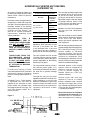
Pipe directly into the combination valve (see Figure
4).
6. A 1/8" N.P.T. plugged tapping, accessible for test
gauge connection, must be installed immediately
upstream of the gas supply connection to the
appliance.
7. Provide a drip leg in the gas piping near the gas
unit heater. A ground joint union and a manual gas
shutoff valve should be installed ahead of the unit
heater controls to permit servicing. The manual
shutoff valve must be located external to the jacket.
(See Figure 4)
8. Make certain that all connections have been
adequately doped and tightened.
Do not over tighten the inlet gas
piping into the valve. This may cause stresses that
will crack the valve!
Table 3A - Gas Piping Requirements
The appliance must be isolated from the gas supply
piping system by closing its individual manual shutoff
valve during any pressure testing of the gas supply
piping system at test pressures equal to or less than
1/2 psig (3.5 kPa).
NOTICE: Use pipe joint sealant resistant to the action
of liquefied petroleum gases regardless of gas
conducted.
Check all pipe joints for leakage
using a soap solution or other approved method.
Never use an open flame or severe personal
injury or death may occur!
Figure 4 - Pipe Installation, Standard Controls
Never use an open flame to
detect gas leaks. Explosive conditions may exist
which may result in personal injury or death!
The appliance and its individual shutoff valve must be
disconnected from the gas supply piping system during
any pressure testing of that system in excess of 1/2
psig (3.5 kPa).
SINGLE STAGE GAS PIPING REQUIREMENTS*
GasType
Natural Gas
Propane (LP) Gas
Manifold
Pressure
3.5 in. W.C.
(0.9 kPa)
10.0 in. W.C.
(2.5 kPa)
14.0 in. W.C. Max.
(3.5 kPa)
14.0 in. W.C. Max.
(3.5 kPa)
5.0 in. W.C. Min.
(1.2 kPa)
11.0 in W.C. Min.
(2.7 kPa)
Supply Inlet
Pressure
*For single stage application only at normal altitudes.
8
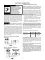
ELECTRICAL CONNECTIONS
THERMOSTAT WIRING AND LOCATION:
NOTICE: The thermostat must be mounted on a
vertical, vibration-free surface, free from air currents,
and in accordance with the furnished instructions.
HAZARDOUS VOLTAGE!
DISCONNECT ALL ELECTRIC
POWER INCLUDING REMOTE
DISCONNECTS BEFORE
SERVICING. Failure to
disconnect power before
servicing can cause severe
personal injury or death.
Mount the thermostat approximately 5 feet (1.5m) above
the floor, in an area where it will be exposed to a free
circulation of average temperature air. Always refer to
the thermostat instructions, as well as our unit wiring
diagram, and wire accordingly. Avoid mounting the
thermostat in the following locations:
1. Cold Areas- Outside walls or areas where drafts
may affect the operation of the control.
2. Hot Areas- Areas where the sun's rays, radiation, or
warm air currents may affect the operation of the
control.
3. Dead Areas- Areas where the air cannot circulate
freely, such as behind doors or in corners.
Standard units are shipped for use on 115 volt, 60 hertz,
single phase electric power. The motor name-plate and
electrical rating of the transformer should be checked
before energizing the unit heater electrical system. All
external wiring must conform to the latest edition of
ANSI/NFPA No. 70-2002, National Electrical Code, and
applicable local codes; in Canada, to the Canadian
Electrical Code, Part 1, CSA Standard C22.1.
THERMOSTAT HEAT ANTICIPATOR ADJUSTMENTS:
The initial heat anticipator setpoint should equal the
thermostat's current amperage draw when the unit is
firing. This setpoint should be measured for the best
results. Use the recommended ranges for a guide. If
further information is needed, consult your thermostat
manufacturer's instructions.
Do not use any tools (i.e. screwdriver,
pliers, etc.) across terminals to check for power.
Use a voltmeter.
It is recommended that the electrical power supply to
each unit heater be provided by a separate, fused, and
permanently live electrical circuit. A disconnect switch of
suitable electrical rating should be located as close to
the gas valve and controls as possible. Each unit heater
must be electrically grounded in accordance with the
latest edition of the National Electrical Code, ANSI/NFPA
No. 70-2002, or CSA Standard C22.1. Refer to Figures
5A, 5B, 5C, 5D and 5E.
Recommended heat anticipator setting ranges:
Gas Ignition Type
For Tubular Units:
Figure 5A - Low-voltage Thermostat Wiring
Single Stage
25 ft. (7.6m)
T'stat Wiring
50 ft. (15.2m)
T'stat Wiring
0.85 to 0.90
A
0.90 to 1.1 A
Max. Setting
on T'stat
FAN TIME DELAY CONTROL: Leads from the fan time
delay control are factory wired to the junction box. The
fan time delay control is a time delay relay (approximately
45 seconds ON, 65 seconds OFF). The fan time delay
control is rated at 17 amps.
NOTICE: The start-up fan delay should not exceed
90 seconds from a cold start.
IMPORTANT: For all wiring connections, refer to the
wiring diagram shipped with your unit (either affixed
to the side jacket or enclosed in the installation
instructions envelope). Should any original wire
supplied with the heater have to be replaced, it must
be replaced with wiring material having a temperature
rating of at least 105° C.
Figure 5B - T834H-1009 or T834H-1017
Thermostat Wiring
9
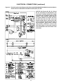
ELECTRICAL CONNECTIONS (continued)
Figure 5C - Tubular Propeller Units Equipped with (Alternate) SV9500/9600/SV9501/SV9601 Gas Valve Module:
Tubular 30 thru 90 Unit Sizes with Natural and Propane (LP) Gas
NOTICE: See Figures 5A, 5B, 5C, 5D and
5E for connecting the thermostat to the
unit heater. If using a standard low voltage
thermostat with a sub-base switch for fan
control, a relay must be added. Remove
the jumper between G and W1 and move
the blue wire from G to W1 on the unit
heater terminal block. Connect the relay
coil to G and the 24 volt common side of
the transformer (white wires). Connect
relay switch to terminals 1 and 3 of fan
time delay switch. Connect the G terminal
of the thermostat to the G terminal of the
unit heater.
10
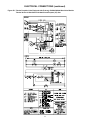
ELECTRICAL CONNECTIONS (continued)
Figure 5D - Tubular Propeller Units Equipped with (Primary) SV9540/SV9640 Gas Valve Module:
Tubular 30 thru 90 Unit Sizes with Natural and Propane (LP) Gas
11
ELECTRICAL CONNECTIONS (continued)
Figure 5E - Tubular Propeller Units Equipped with (Alternate) S8600 Intermittent Pilot Ignition System:
Tubular 30 thru 90 Unit Sizes with Natural and Propane (LP) Gas
12
VENTING*
All unit heaters must be vented! All Venting installations shall be in accordance with the latest edition of Part 7,
Venting of Equipment of the National Fuel Gas Code, ANSI Z223.1, or applicable provisions of local building
codes.
CARBON MONOXIDE! Your venting system must not be blocked by any snow, snow
drifts, or any foreign matter. Inspect your venting system to ensure adequate ventilation exists at all
times! Failure to heed these warnings could result in Carbon Monoxide Poisoning (symptoms include
grogginess, lethargy, inappropriate tiredness, or flu-like symptoms).
When an existing heater is removed or replaced in
venting system, the venting system may not be properly
sized to vent the attached appliances. An improperly
sized vent system can cause formulation of condensate
or leakage or spillage of flue gases.
5. Test the draft hood equipped appliance spillage at
the draft hood relief opening after 5 minutes of main
burner operation. Use the flame of a match or
candle.
6. After it has been determined that each appliance
connected to the venting system properly vents
when tested as outline above, return doors,
windows, exhaust fans, fireplace dampers, and any
other gas-burning appliance to their previous
condition of use.
7. If improper venting is observed during any of the
above tests, the venting system must be corrected
immediately so that the system conforms with the
National Fuel Gas Code, ANSI Z223.1. When
resizing any portion of the venting system, the
venting system should be resized to approach the
minimum size as determined using the appropriate
tables in Appendix G of the National Fuel Gas Code,
ANSI Z223.1.
The following steps shall be followed with each appliance
connected to the venting system placed in operation,
while any other appliances connected to the venting
system are not in operation:
1. Seal any unused openings in the venting system;
2. Inspect the venting system for proper size and
horizontal pitch, as required in the National Fuel
Gas Code, ANSI Z223.1 and these instructions.
Determine that there is no blockage or restriction,
leakage, corrosion and other deficiencies, which
could cause an unsafe condition.
3. In so far as practical, close all building doors and
windows and all doors between the space in which
the appliance(s) connected to the venting system
are located and other spaces of the building. Turn
on clothes dryers and any exhaust fans, such as
range hoods and bathroom exhausts, so they shall
operate at maximum speed. Do not operate a
summer exhaust fan. Close fireplace damper.
4. Follow the lighting instructions. Place the appliance
being inspected in operation. Adjust thermostat so
that the appliance will operate continuously.
The unit heater shall be connected to a factory built
chimney or vent complying with a recognized standard,
or a masonry or concrete chimney lined with a lining
material acceptable to the authority having jurisdiction.
Venting into an unlined masonry chimney is
prohibited.
ADDITIONAL REQUIREMENTS FOR CANADIAN INSTALLATIONS
*The following instructions apply to Canadian installations in addition to installation and operating instructions.
1. Installation must conform with local building codes, or in the absence of local codes, with current
CGA-B149.1, Installation Codes for Natural Gas Burning Appliances and Equipment, or CGA-B149.2, Installation
Codes for Propane Gas Burning Appliances and Equipment.
2. Any reference to U.S. standards or codes in these instructions are to be ignored and the applicable Canadian
standards or codes applied.
3. Canadian units include the vent cap (supplied by the manufacturer).
13
VENTING
ANSI now organizes vented
appliances into four categories.
Venting Categories
Negative
Vent
Pressure
Positive
Vent
Pressure
Non
Condensing
Condensing
I
II
III
Category I
Includes non-condensing
appliances with negative vent
pressure, like the traditional
atmospheric unit heater.
Category II
Groups condensing appliances
with negative vent pressure.
IV
Category III
Appliances are non-condensing
and operate with a positive vent
pressure.
Category IV
Covers condensing appliances
with positive vent pressure.
NOTICE: Category II and IV do
not apply to equipment specified
within this manual.
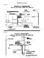
VERTICALLY VENTED UNIT HEATERS
(CATEGORY I)
4.
5.
6.
7.
Observe the following precautions when venting the unit:
The unit heater shall be connected to a factory built
chimney or vent complying with a recognized standard,
or a masonry or concrete chimney lined with a lining
material acceptable to the authority having jurisdiction.
Venting into an unlined masonry chimney is
prohibited.
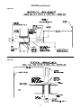
1. Use flue pipe of the same size as the flue
connections on the gas unit heater, 4 inch (102mm).
All heaters must be vented with UL Listed Type B
vent, or single wall pipe.
2. Provide as long a vertical run of flue pipe at the gas
unit heater as possible. A minimum of five feet
(1.5m) of vertical flue is required. The top of the
vent pipe should extend at least two feet (0.61m)
above the highest point on the roof. Install a weather
cap over the vent opening.
3. Slope horizontal runs upward from the gas unit
heater at least 1/4-inch per foot (21mm/m).
Horizontal runs should not exceed 75% of the
vertical height of the vent pipe, or chimney, above
the flue pipe connection, up to a maximum length
of 10 feet (3m). Horizontal portions of the venting
system shall be supported at maximum intervals of
four feet (1.22m). (See Figure 6)
8.
9.
10.
11.
Figure 6
14
Use as few elbows as possible.
Tape flue pipe joints with fireproof paper or material.
Avoid running vent pipe through unheated spaces.
When this cannot be avoided, insulate the pipe to
prevent condensation of moisture on the walls of
the pipe. Insulate vent pipe runs longer than 10 feet
(3m). Insulation should be a minimum of 1/2 inch
(12.7mm) thick foil faced fiberglass, 1-1/2# density
insulation.
Do not damper the flue piping. Failure to open such
a damper prior to operating the gas unit heater will
result in the spillage of flue gas into the occupied
space.
Avoid installing units in areas under negative
pressure due to large exhaust fans or air
conditioning. When required, a flue vent fan should
be installed in accordance with the instructions
included with the fan.
Vent connectors serving Category I and Category
II heaters shall not be connected into any portion of
mechanical draft systems operating under positive
pressure.
Also refer to Figures 8B and 9B for additional
requirements.
HORIZONTALLY VENTED UNIT HEATERS
(CATEGORY III)
All venting of residential tubular unit
heaters must comply with the latest
edition of CSA . 10.96 U.S. (2nd ed.)
requirement.
Horizontal venting arrangements are
designed to be used with single wall
vent pipe. These arrangements must
terminate external to the building
using either single wall or double wall
(Type B) vent. See Figures 7, 8A
and 9A for special installation
requirements regarding these
venting conditions.
TYPE
B
(DOUBLE WALL) VENT TO
TYPE B VENT CONNECTIONS
ARE NOT ALLOWED INTERNALLY WITHIN THE BUILDINGS ON HORIZONTALLY
VENTED POWER VENTED
UNITS.
TRANSITIONS FROM THE
RECOMMENDED SINGLE
WALL TO TYPE B VENT PIPE
IS ONLY ALLOWED INTERNALLY WITHIN THE BUILDING
AT THE POINT OF BUILDING
TERMINATION.
If double wall venting is used,
components which are UL Listed and
approved for Category III positive
pressure venting systems MUST be
used.
A Breidert Type L, Fields Starkap,
or equivalent vent cap must be
supplied by the customer for each
power vented unit (Canadian units
are equipped with the vent cap). The
vent pipe diameter MUST be 4
inches (102mm).
Vent Systems
Termination Clearance Requirements
Minimum
Clearances for
Termination
Locations
Structure
4 feet
below
Door, window or
any gravity air inlet
4 feet
horizontally
1 foot
above
Forced air inlet within 10 ft.
3 feet
above
Adjoining building or parapet 6 feet
Adjacent public walkways
7 feet
above grade
The venting system for these
appliances shall terminate at least
four feet (1.2m) below, four feet
(1.2m) horizontal from, or one foot
(0.3m) above any door, window, or
gravity vent air inlet into the building.
The vent terminal must be at least
12 inches (305mm) from the exterior
of the wall that it passes through to
prevent degradation of the building
material by flue gases.
The vent pipe equivalent length must
not exceed 30 feet (9.14m) for the
30 and 45 unit sizes, and 40 feet
(12.2m) for the 60 and 75 unit sizes.
Equivalent length is the total length
of straight sections PLUS 5 feet
(1.52m) for each 90 elbow and 2.5
feet (0.76m) for each 45 elbow.
Maintain 1 inch (25.4mm) between
the vent pipe and combustible
materials.
The vent terminal must be installed
with a minimum horizontal clearance
of four feet (1.2m) from electric
meters, gas meters, regulators, and
relief equipment.
Seal all vent pipe joints and seams to
prevent leakage.Use General Electric
RTV-108, Dow-Corning RTV-732
silicone sealant; or 3M #425
aluminum foil tape. The vent air
system must be installed to prevent
collection of condensate. Pitch
horizontal pipes downward 1/4 inch
per foot (21mm per meter) toward the
outlet for condensate drainage
The vent terminal must be at least 1
foot (305mm) above grade, or in
snow areas, at least three feet above
the snow line to prevent blockage
by snow.
Horizontal portions of the venting
systems shall be supported at
maximum intervals of four feet
(1.2m) to prevent sagging (in
Canada, support at 3 feet (1m)
minimum intervals).
Through the wall vent for these
appliances shall NOT terminate over
public walkways, or over an area
where the condensate or vapor could
create a nuisance or hazard or could
be detrimental to the operation of
regulators, relief valves, or other
equipment.
Insulate single wall vent pipe
exposed to cold air or running
through unheated areas. Insulate
vent pipe runs longer than 10 feet
(3m). Insulation should be a minmum
of 1/2 inch thick foil faced fiberglass,
1-1/2# density insulation.
Each unit must have an individual
vent pipe and vent terminal! Each
unit MUST NOT be connected to
other vent systems or to a chimney.
Figure 7
15
VENTING (continued)
Figure 8A
Figure 8B
16
VENTING (continued)
Figure 9A
Figure 9B
17
OPERATION
POWER VENTED PROPELLER UNITS
INTERMITTENT PILOT IGNITION
EXPLANATION OF CONTROLS (See Figure 10):
1. The unit heater is equipped with a power venter
system consisting of a power venter motor and
blower, pressure switch, and sealed flue collector in
place of the conventional draft diverter.
2. The power venter motor is energized by the room
thermostat on a call for heat. The pressure switch
measures the flow through the vent system and
energizes the indirect ignition system when the flow
is correct. The pressure switch MUST NOT be
bypassed. The unit MUST NOT be fired unless
the power venter is operating. An unsafe
condition could result.
3. The indirect ignition system consists of an ignition
control module, a dual combination valve, and a
pilot burner. When the pressure switch closes, the
pilot valves opens and the pilot burner is ignited by
either a spark or hot surface element. When flame
sensing circuit senses that the pilot flame is
established, the main gas valve is opened to supply
gas to the main burners. When the thermostat is
satisfied, the vent system is deenergized and both
valves are closed to stop all flow of gas to the unit.
4. The limit switch interrupts the flow of electric current
to the main gas valve in case the heater becomes
overheated.
5. The flame roll-out switch acts to shut off the gas
supply to the heater in the event of sustained flame
roll-out from the burner area. If this switch trips,
DETERMINE AND CORRECT THE CAUSE of the
flame roll-out. (See Trouble Shooting Guide,
Symptoms E and H.) Push the red reset button to
restart the heater.
6. The fan switch delays the operation of the fan until
the heater is warmed, then keeps the fan running
after the gas has been turned off until the useful heat
has been removed. The startup fan delay must
not exceed 90 seconds from a cold start.
7. The wall thermostat (supplied
optionally) is a temperature
sensitive switch which operates
the vent system and the ignition
system to control the temperature
of the space being heated. It must
be mounted on a vibration free,
vertical surface away from air
currents, in accordance with the
instructions furnished with the
thermostat (also refer to Electrical
Section).
START-UP (Also refer to lighting instruction plate
equipped on the unit)
1. Open the manual valve supplying gas to the unit
heater, and with the union connection loose, purge
air from the gas line. Tighten the union and check
for gas leaks.
Never use an open flame to detect
gas leaks. Explosive conditions may exist which
could result in personal injury or death.
Before attempting to light or
relight pilot, wait 5 minutes to allow gas which
may have accumulated in the burner compartment to escape.
2. Open the manual valve on the unit heater.
3. Turn ON electrical power.
4. The unit should be under the control of the
thermostat. Turn the thermostat to the highest point
and determine that the power venter motor starts,
and the pilot and main burners ignite. Turn the
thermostat to the lowest point and determine that
the power venter motor shuts off and the pilot and
main burners are extinguished.
5. If pilot adjustment is required, remove the pilot
adjustment seal cap and adjust the pilot screw to
obtain proper flame. Clockwise rotation decreases
pilot flame size. Replace the cap.
6. Turn the thermostat to the desired position.
7. See Gas Input Rate and Adjustments sections.
SHUT DOWN
1. Turn the valve selector knob to the “OFF” position.
2. Turn off the electricity.
3. To relight, follow the “start-up” instructions.
See Figure 10 for parts/identification.
Figure 10
18
PRIMARY AIR SHUTTER ADJUSTMENT
Primary air adjustment is made at the factory. No field adjustments are necessary.
GAS INPUT RATE
2. PROPANE GAS: An exact manifold pressure of
10.0 inches W.C. (2.5 kPa) must be maintained for
proper operation of the unit heater. If the unit is
equipped with a pressure regulator on the
combination gas valve, follow steps "a" through "d"
above. If the unit is not so equipped, the propane
gas supply system pressure must be regulated to
attain this manifold operating pressure.
3. The adjusted manifold pressure should not vary
more than 10% from pressure specified in Tables
3B & 4.
Check the gas input rate as follows (Refer to General
Safety Information section for metric conversions).
Never overfire the unit heater, as this
may cause unsatisfactory operation, or shorten the
life of the heater.
1. Turn off all gas appliances that use gas through the
same meter as the unit heater.
2. Turn the gas on to the unit heater.
3. Clock the time in seconds required to burn 1 cubic
foot of gas by checking the gas meter.
4. Insert the time required to burn one cubic foot of
gas into the following formula and compute the input
rate.
3600 (Sec. per Hr.) X BTU/Cu. Ft.
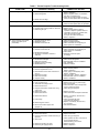
Table 3B - Main Burner Orifice Schedule*
= Input Rate
Time (Sec.)
TYPE OF GAS
NATURAL
PROPANE
*
HEATING VALUE
1075 BTU/Ft3
2500 BTU/Ft3
INPUT
IN
1000
BTU
(40.1 MJ/m3)
(93.1 MJ/m3)
MANIFOLD
PRESSURE
3.5" W.C.
(0.87kPA)
10" W.C.
(2.49 kPA)
FT 3/HR
ORIFICE DRILL
FT 3/HR
ORIFICE DRILL
FT 3/HR
ORIFICE DRILL
FT 3/HR
ORIFICE DRILL
FT 3/HR
ORIFICE DRILL
28
49
42
49
56
49
70
49
84
47
12
57
18
57
24
57
30
57
36
55
30
For example:
Assume the BTU content of one cubic foot of gas is
1000, and that it takes 48 seconds to burn one cubic
foot of gas.
3600 x 1000
= 75,000
48
45
60
75
90
NO. OF
BURNER
ORIFICES
2
3
4
5
5
*This schedule is for units operating at normal altitudes of 2000 ft. (610m)
or less.
NOTICE: If the computation exceeds, or is less than
95% of the gas BTU/hr. input rating (see Table 1),
adjust the gas pressure.
When installed in Canada, any references to deration at altitudes in excess
of 2000 ft. (610m) are to be ignored. At altitudes of 2000 to 4500 ft. (610 to
1372m), the unit heaters must be orificed to 90% of the normal altitude
rating, and be so marked in accordance with CSA certification.
Adjust the gas pressure as follows:
TUBULAR UNIT HEATER
HIGH ALTITUDE DERATION
This Tubular Unit Heater has been manufactured utilizing
standard burner orifices and a normal manifold pressure
setting as per the specifications shown on your unit
rating plate (refer to Tables 3A, 3B and 4).
1. NATURAL GAS: Best results are obtained when
the unit heater is operating at its full rated input
with the manifold pressure of 3.5 inches W.C. (0.9
kPa). Adjustment of the pressure regulator is not
normally necessary since it is preset at the factory.
However, field adjustment may be made as follows:
a. Attach manometer at the pressure tap plug below
the control outlet.
b. Remove the regulator adjustment screw cap,
located on the combination gas valve.
c. With a small screwdriver, rotate the adjustment
screw counterclockwise to decrease pressure,
or clockwise to increase pressure.
d. Replace regulator adjustment screw cap.
All unit deration must be done through field adjustments
by a qualified technician (refer to Table 4). Once the
proper adjustments are made in the field, attach label
#J17-06459 to the unit, and record adjusted manifold
pressure, altitude of the unit installation and the
technician’s name and date on the label using a
permanent marker.
19
Table 4
NATURAL GAS
Altitude
(Feet)
2,000
2,500
3,000
3,500
4,000
4,500
5,000
5,500
6,000
*Heating
Value
BTU/Cu. ft.
948
931
914
897
881
865
849
833
818
Manifold
Pressure
(In. W.C.)
3.2
3.2
3.2
3.1
3.1
3.1
3.0
3.0
2.9
PROPANE (LP) GAS
*Heating
Value
BTU/Cu. ft.
2,278
2,237
2,196
2,156
2,116
2,077
2,039
2,000
1,964
NATURAL GAS
Manifold
Pressure
(In. W.C.)
10.0
10.0
10.0
10.0
10.0
9.9
9.7
9.6
9.5
Altitude
(Feet)
6,500
7,000
7,500
8,000
8,500
9,000
9,500
10,000
*Heating
Value
BTU/Cu. ft.
802
787
771
756
741
726
711
696
Manifold
Pressure
(In. W.C.)
2.9
2.8
2.8
2.8
2.7
2.6
2.6
2.5
PROPANE (LP) GAS
*Heating
Value
BTU/Cu. ft.
1,927
1,891
1,853
1,817
1,781
1,745
1,709
1,673
Manifold
Pressure
(In. W.C.)
9.3
9.2
9.0
8.9
8.7
8.5
8.3
8.1
*Notes:
1. Consult local utility for actual heating value.
2. Tables based on heating value of 1,050 BTU/Cu. ft. at sea level.
MAINTENANCE
5. With the burners removed, wire brush the inside
surfaces of the heat exchanger.
6. Remove any dirt, dust, or other foreign matter from
the burners using a wire brush and/or compressed
air. Ensure that all parts are unobstructed. Inspect
and clean the pilot burner if necessary.
7. Reassemble the unit heater by replacing all parts in
reverse order.
8. Complete the appropriate unit startup procedure as
given in the "Operation" section of this manual. (See
lighting instruction on the unit nameplate).
9. Check the burner adjustment.
10. Check all gas control valves and pipe connections
for leaks.
11 Check the operation of the automatic gas valve by
lowering the setting of the thermostat, stopping the
operation of the gas unit heater. The gas valve
should close tightly, completely extinguishing the
flame on the main burners.
12. Inspect and service motor/fan assembly. To maintain
efficient air flow, inspect and clean the fan blades
and guard to prevent buildup of foreign matter.
13. Check lubrication instructions on motor. If oiling is
required, add 3 or 4 drops of electric motor oil as
follows:
a. Light Duty - After 3 years or 25,000 hours of
operation.
b. Average Duty - Annually after 3 years or 8,000
hours of operation.
c. Heavy Duty - Annually after 1 years or at least
1500 hours of operation.
PERIODIC SERVICE
NOTICE: The heater and vent system should be
checked once a year by a qualified technician.
All Maintenance/Service information should be recorded
accordingly on the Inspection Sheet provided in this
manual.
Open all disconnect switches and
disconnect all electrical and gas supplies and
secure in that position before servicing unit.
Failure to do so may result in personal injury or
death from electrical shock.
Should maintenance be required, perform the following
inspection and service routine:
1. Inspect the area near the unit to be sure that there
is no combustible material located within the
minimum clearance requirements listed in this
manual.
Under no circumstances should
combustible material be located within the
clearances specified in this manual. Failure to
provide proper clearance could result in
personal injury or equipment damage from fire.
2. Turn off the manual gas valve and electrical power
to the unit heater.
3. Remove service panel.
4. To clean or replace the main burners, remove the
four screws holding the manifold to the burner box
and pull the manifold back slightly to disengage the
orifices from the main burners. Remove each burner
by holding it against the tab on the burner bracket,
then rotate the inlet end of the burner toward the
fan side of the unit and slide the burner off the tabs.
See Figure 10.
Never over oil the motor or premature
failure may occur!
14. Check and test the operational functions of all safety
devices supplied with your unit.
20
Table 5 - Tubular Propeller Troubleshooting Guide
SYMPTOMS
A. Flame lifting from burner ports.
POSSIBLE CAUSE(S)
1. Pressure regulator set too high.
2. Defective Regulator.
3. Burner orifice too large.
CORRECTIVE ACTION
1. Reset manifold pressure.
Refer to “Operation”.
2. Replace regulator section of combination
gas valve or complete valve.
3. Check with local gas supplier for proper
orifice size and replace. Refer to “Operation”.
B. Flame pops back.
1. Burner orifice too small.
1. Check with local gas supplier for proper
orifice size and replace. Refer to “Operation”.
C. Noisy flame.
1. Noisy pilot
2. Irregular orifice causing whistle or resonance.
3. Excessive gas input.
1. Reduce pilot gas. Refer to “Operation”.
2. Replace orifice.
3. Reset manifold pressure. Refer to
“Operation”; Replace regulator section of
combination gas valve or complete valve;
Check with local gas supplier
for proper orifice size and replace.
Refer to “Operation”.
D. Yellow tip flame (some yellow
tipping on propane gas is
permissible).
1. Clogged main burner ports.
2. Misaligned orifices.
3. Insufficient combustion air.
1. Clean main burner ports.
2. Replace manifold assembly.
3. Clean combustion air inlet openings in
bottom panel, see “Installation”.
E. Floating flame.
1. Blocked venting.
2. Insufficient combustion air.
3. Blocked heat exchanger.
4. Air leak into combustion chamber or
draft hood.
1. Clean flue. Refer to “Installation”.
2. Clean combustion air inlet openings in
bottom panel, see “Installation”.
3. Clean heater.
4. Determine cause and repair
accordingly.
F. Gas Odor.
1. Shut off gas supply immediately!
2. Blocked heat exchanger.
3. Drafts around heater.
4. Negative Pressure in building.
5. Blocked draft hood.
1. Inspect all gas piping and repair.
2. Clean heat exchanger/flue.
3. Eliminate drafts. Refer to “Installation”.
4. See “Installation”.
5. Clean flue collector.
G. Delayed ignition.
1. Main burner ports clogged near pilot.
2. Pressure regulator set too low.
1. Clean main burner ports.
2. Reset manifold pressure.
Refer to “Operation”.
3. Supply piping is inadequately sized.
Refer to “Installation”.
4. Clean pilot orifice. Refer to “Operation”.
5. Eliminate drafts. Refer to “Installation”.
6. Refer to “Installation”.
3. Pilot decreases in size when main burners
come on.
4. Pilot flame too small.
5. Drafts around heater.
6. Improper venting.
H. Failure to ignite.
1. Main gas off.
2. Lack of power at unit.
3. Thermostat not calling for heat.
4. Defective limit switch.
5. Improper thermostat or transformer wiring
at gas valve.
6. Defective gas valve.
7. Defective thermostat
8. Defective transformer.
9. Loose wiring.
10. Defective ignition control.
11. Flame roll-out switch tripped, see
Symptom E.
1. Open all manual gas valves.
2. Replace fuse or turn on power supply.
3. Turn up thermostat
4. Check limit switch with continuity tester.
If open, replace limit switch.
5. Check wiring per diagrams.
6. Replace gas valve.
7. Check thermostat and replace if defective.
8. Replace, if necessary. Also see W, X
& Y symptoms.
9. Check and tighten all wiring
connections per diagrams.
10. Replace, if necessary. Also see W, X,
& Y symptoms.
11. Push red reset button.
J. Condensation of water vapor.
1. Improper venting.
1. Refer to “Installation, Venting”.
K. Burner won't turn off.
1. Poor thermostat location.
2. Defective thermostat
3. Improper thermostat or transformer wiring at
gas valve.
4. Short circuit.
1. Relocate thermostat away from drafts.
2. Replace thermostat.
3. Check wiring per diagrams.
5. Defective or sticking gas valve.
6. Excessive gas supply pressure.
21
4. Check operation at valve. Look for short
(such as staples piercing
thermostat wiring), and correct.
5. Replace gas valve.
6. Refer to “Operation”.
Table 5 - Tubular Propeller Troubleshooting Guide (continued)
SYMPTOMS
L. Rapid burner cycling.
POSSIBLE CAUSE(S)
1. Loose wire connections at gas valve
or thermostat.
2. Excessive thermostat heat anticipation.
3. Unit cycling on high limit.
4. Poor thermostat location.
5. Draft on Pilot.
6. Defective ignitor control.
7. Defective high limit.
M. Noisy power ventor.
1. Power ventor wheel loose.
2. Power ventor wheel dirty.
3. Power ventor wheel rubbing housing.
4. Bearings are dry.
N. Pilot will not light or will not
stay lit.
1. Main gas valve off.
2. Pilot adjustment screw turned too low
on combination main gas valve.
3. Air in gas line.
4. Incorrect lighting procedure.
5. Dirt in pilot orifice.
6. Extremely high or low gas pressure.
7. Defective spark cable.
8. Drafts around unit.
9. Pilot valve not opening (faulty wiring).
10. Pilot element not glowing or no spark
(faulty wiring).
11. Defective gas valve.
O. Fan will not run.
1. Loose wiring.
2. Defective motor overload protector or
defective motor.
3. Defective fan switch.
P. Fan motor turns on and off while
burner is operating.
1. Fan switch heater element improperly
wired.
2. Defective fan switch.
3. Motor protector cycling ON and OFF.
4. Motor not properly oiled.
Q. Fan motor will not stop.
R. Not enough heat.
CORRECTIVE ACTION
1. Tighten all electrical connections.
2. Adjust thermostat heat anticipator for
longer cycles. Refer to “Operation”.
3. Check for proper air supply across
heat exchanger.
4. Relocate thermostat. (Do not mount
thermostat on unit).
5. Eliminate drafts. Refer to “Installation”.
6. Replace ignitor.
7. Jumper high limit switch terminals 1 and 2.
If burner operates normally, replace switch.
1. Replace or tighten.
2. Clean power ventor wheel.
3. Realign power ventor wheel.
4. Oil bearings on power ventor motor.
(Refer to label on motor).
1. Open all manual gas valves.
2. Increase size of pilot flame.
Refer to “Operation”.
3. Purge air from gas line.
4. Follow lighting instruction label
adjacent to gas valve.
5. Remove pilot orifice. Clean with
compressed air or solvent. (Do not ream).
6. Refer to “Operation”.
7. Check cable connections, and
replace if defective.
8. Eliminate drafts. Refer to “Installation”.
9. Inspect and correct wiring.
10. Inspect and correct ignition system wiring.
See symptoms W, X, & Y.
11. Replace gas valve.
1. Check and tighten all wiring
connections per diagrams.
See “Electrical Connections”.
2. Replace motor.
3. Check for 24V across H terminals on fan time
delay switch. If 24V is present, jumper
terminals numbered 1 and 3. If motor runs,
the fan switch is defective and must be
replaced. If 24V is not present, check wiring
per diagrams.
1. Be sure fan switch heater terminals are
connected per diagrams.
2. Replace fan switch.
3. Check motor amps against motor name
plate rating, check voltage, replace fan
motor if defective.
4. Refer to label on motor.
1. Improperly wired fan control.
2. Main burners not lighting while thermostat
calls for heat.
3. Defective fan switch.
1. Check all wiring.
2. Refer to H or N symptoms.
1. Incorrect gas input.
2. Heater undersized.
1. Refer to “Operation”.
2. This is especially true when the heated
space is enlarged. Have the heat loss
calculated and compare to heater
output (80% of input). Your gas
supplier or installer can furnish this
information. If heater is undersized,
add additional heaters.
3. Replace thermostat.
4. There should be NO ducts attached to the
front of this heater. Check air movement
through heat exchanger. Check voltage
to fan motor. Clean fan blade and heat
exchanger and oil fan motor.
3. Thermostat malfunction.
4. Heater cycling on high limit .
22
3. Replace fan switch.
Table 5 - Tubular Propeller Troubleshooting Guide
SYMPTOMS
POSSIBLE CAUSE(S)
CORRECTIVE ACTION
S. Too much heat.
1. Thermostat malfunction.
2. Heater runs continuously.
1. Replace thermostat.
2. Check wiring per diagrams; Check operation
at valve. Look for short (such as staples
piercing thermostat wiring) and correct:
Replace gas valve, Refer to “Operation”.
T. Cold air is delivered on start up.
1. Fan relay heater element improperly
wired.
1. Be sure fan relay heater terminal are
connected per diagrams.
U. Cold air is delivered during heater
operation.
1. Incorrect manifold pressure or input.
2. Voltage to unit too high.
1. Refer to “Operation”.
2. Check motor voltage with fan running.
Should be 115 volts AC.
3. Refer to “Operation”.
3. Air throughput too high.
V. Hot surface element not glowing or
NO spark (some models).
1. Thermostat not calling for heat.
2. No low voltage.
3. Spark gap closed or too wide.
4. Broken or cracked ceramic on spark
electrode.
5. Broken hot surface element.
W. Ignition source present, but pilot
does not light.
1. Loose ignitor connections .
2. Improper gas pressure.
3. Is ignition source in pilot gas stream?
4. No pilot gas — do not use match to
test - presence of gas is easily
detected by the odor.
X. Pilot lights — Main valve does
not energize.
1. Loose ignitor connections.
2. Cracked or broken sensor ceramic.
3. Check sensor/spark lead for continuity.
4. Measure 24 volts from terminals MV to
terminals MV/PV.
Y. Hi-Limit switch tripping.
3. Defective switch.
AA.Power ventor will not run.
1. Check connections - terminal MV feeds
main valve.
2. Replace pilot assembly.
3. Replace if needed.
4. If present, replace main valve; if not,
replace igniter.
1. Replace or tighten.
2. Clean power ventor wheel.
3. Realign power ventor wheel.
4. Oil bearings on power ventor motor.
(Refer to label on motor).
1. Loose wiring.
1. Check and tighten all wiring connections
per diagrams. See “Electrical Connections”.
2. Replace motor.
1. Power ventor relay improperly wired.
2. Defective ventor relay switch.
3. Motor overload protector cycling on and off.
4. Motor not properly oiled.
CC. Power ventor motor will not stop.
1. Check all connections - terminal PV feeds
24V to the pilot valve.
2. Check pressure — pressure too high
or too low may cause a problem.
3. Spark should arc from electrode.
4. Check pilot line for kinks. Insure there are
no drafts.
1. Power ventor wheel loose.
2. Power ventor wheel dirty.
3. Power ventor wheel rubbing housing.
4. Bearings are dry.
2. Defective motor overload protector or
defective motor.
3. Defective power ventor relay.
BB. Power ventor turns on and off
while burners are operating.
5. Replace hot surface element.
1. Burner orifice may be too large:
verify/replace if required.
2. Increase air flow; check fan size.
Check for proper voltage.
3. Replace.
1. Unit is overfiring.
2. Air flow too low
Z. Noisy power ventor.
1. Close thermostat contacts.
2. Check for 24V across 24V terminals
of ignitor.
3. Set gap to 0.1".
4. Replace pilot assembly.
1. Improperly wired ventor relay.
2. Main burners not lighting while
thermostat calls for heat.
3. Defective ventor relay.
23
3. Check for 24V across 1 and 3 terminals on
fan relay. If 24V is present, jumper terminals
numbered 2 and 4. If motor runs, the relay
is defective and must be replaced. If 24V is
not present, check wiring per diagrams.
1. Be sure ventor relay terminals are
connected per diagrams.
2. Replace ventor relay.
3. Check motor amps against motor
name plate rating, check voltage,
replace power ventor motor if defective.
4. Refer to label on motor.
1. Check all wiring.
2. Refer to H and N Symptoms.
3. Replace ventor relay.
Table 6 - Troubleshooting with LED Indicator Assistance
No Cycling or appliance power
INDICATES
CHECK/REPAIR
LED STATUS
or thermostat call for heat
Off
No power to system control
1. Line voltage input power at L1
since appliance failure has
and L2 connector.
2. Low voltage (24V) power at 24
occured.
Line voltage power can
cause product damage,
severe injury or death.
Only a trained experienced
service technician should
perform this troubleshooting.
1. Check the system thermostat to make sure it is calling for heat. (Do not cycle
the thermostat on and off
at this time.)
2. Remove the appliance
burner compartment door.
Do not interrupt power to
the SV9540; SV9640 by
opening any electrically
interlocked panels.
3. Observe the LED indicator
on the SV9540; SV9640;
check and repair system as
noted in the chart to the
right.
*NOTICE: Air flow proving
switch and power venter
hose barbs must be free of
any dust or debris at all
times. Periodically check
these openings and/or if any
problems occur.
VAC and COM.
3. System wiring harness is in good
condition and securely connected
at both ends.
Bright – Dim
Normal operation
This indication shows whenever the
system is powered, unless some
abnormal event has occurred.
Not Applicable
2 Flashes
Airflow proving switch remains closed
longer than 30 seconds after a call for
heat begins.
1. Airflow proving switch stuck
closed.
2. Airflow proving switch miswired or
jumpered.
Combustion air blower is not energized
until airflow proving switch opens.
3 Flashes*
Airflow proving switch remains
open longer than 30 seconds after
combustion air blower energized
System goes into 5-minute delay
period, with combustion air blower off.
At the end of the 5-minute delay,
another ignition cycle will begin.
1. Ignition system control switch
must be in the ON position.
2. Airflow proving switch operation,
tubing and wiring.
3. Obstructions or restrictions in
appliance air intake or exhaust
flue system that prevent proper
combustion airflow.
4 Flashes
Limit string is open.
1. Open manual reset or auto reset
burner rollout switch.
2. Open high temperature or
auxiliary limit switch.
3. Limit and rollout switch wiring is in
good condition and securely
connected.
5 Flashes
Flame signal sensed out of sequence.
1. Flame at pilot burner.
6 Flashes
System Lockout
After 5-minute delay time, control
system will reset and initiate a new
ignition sequence, if the call for heat
is present.
1. Gas supply off or at too low
pressure to operate appliance.
2. Damaged or broken HSI element.
3. Line voltage HOT lead wire not
connected to L1 terminal (check
polarity)
4. Appliance not properly earth
grounded.
5. Flame sense rod contaminated or
in incorrect location.
6. Be sure pilot burner lead wires are
in good condition and properly
connected.
24
IDENTIFICATION OF PARTS
RESIDENTIAL TUBULAR 30-90 MBH UNIT SIZES
Item
No. ItemDescription
1
Vestible Panel/Tube Ass’y
(Heat Exchanger)
2
Manifold Bracket Sub-Ass’y
3
Manifold
4
Inshot Burner
5
*Standard Orifice
Natural Gas or Propane (LP) Gas
6
Pilot Burner Ass’y
Natural or Propane (LP) Gas
7
Pilot Mounting Bracket
8
Pilot Tubing
9
Gas Valve, Single Stage
Natural or Propane (LP) Gas
10
Manual Rollout Safety Switch
11
Fan Time Delay Switch
12
Transformer, 50 VA, 115/24
13
Air Pressure Switch
14
***Draftor Relay
14A
Terminal Block Plate
15
High Limit Switch
w/Mounting Bracket
16
Fan Motor
18
OSHA Fan Guard
19
Standard Fan
20
Fan/Guard/Motor Mount
Hardware Kit
21
**Flue Collector
22
Power Venter (Drafter) Ass’y
23
Flue Collar Ass’y
24
Vinyl Tubing (Pressure Switch)
25
Power Venter Mounting Plate
26
Louver
27
Louver Spring
28
Side Jacket Panel w/Insulation
29
Service Panel
30
Top Jacket Panel w/Insulation
31
Bottom Jacket Panel w/Insulation
32
Front Jacket
33
Rear Jacket
34
Front Hanger
35
Rear Hanger
36
Tube Support Bracket
*** The orifices shown are for units
operating at normal altitudes of 0 to
2000 ft. (610m).
*** When replacing a flue collector, make
sure that the flue collector box is sealed
completely to the vestibule panel using
RTV Sealant.
*** The draftor relay is not required
on units equipped with Honeywell
SV9540/SV9640 Hot Surface Gas
Control.
25
IDENTIFICATION OF PARTS
RESIDENTIAL TUBULAR 30-90 MBH UNIT SIZES
Figure 11 - Propeller Parts
Figure 12 - Component Parts
Fan Blade
Fan Guard
Motor
D4791
Hardware
Hardware
D4787
Pressure Switch
Relay
D4430
NOTE: No rubber grommets are equipped with the 30 and 45
unit sizes.
D4808
D4792
Fan Time Delay Switch
Figure 13 - Internal Furnace Components
Gas Valve
Figure 14 - Power Ventor Assembly
D4810
26
HOW TO ORDER REPLACEMENT PARTS
Please send the following information to your local representative: if further assistance is needed, contact the
manufacturer's customer service department.
•Model Number
•Serial Number (if any)
•Part Description and Number as shown in Replacement parts Catalog
LIMITED WARRANTY
Residential Power Vented Tubular Propeller Unit Heaters
1. The "Manufacturer" warrants to the original owner at original installation site that the above model Gas-Fired
Heater ("the Product") will be free from defects in material or workmanship for (1) year from the date of
shipment from the factory, or one and one-half (1-1/2) years from the date of manufacture, whichever occurs
first. The Manufacturer further warrants that the complete heat exchanger, flue collector and burners be free
from defects in material or workmanship for a period of ten (10) years from the date of manufacture. If upon
examination by the Manufacturer the Product is shown to have a defect in material or workmanship during the
warranty period, the manufacturer will repair or replace, at its option, that part of the Product which is shown
to be defective.
2. This limited warranty does not apply:
a. if the product has been subjected to misuse or neglect, has been accidentally or intentionally damaged,
has not been installed, maintained, or operated in accordance with furnished written instructions, or has
been altered or modified in any way by any unauthorized person.
b. to any expenses, including labor or material, incurred during removal or reinstallation of the Product
c. to any damage due to corrosion by chemicals, including halogenated hydrocarbons, precipitated in the air
d. to any workmanship of the installer of the Product
3. This limited warranty is conditional upon:
a. advising the installing contractor, who in turn notify the distributor or manufacturer
b. shipment to the Manufacturer of that part of the Product thought to be defective. Goods can only be
returned with prior written approval of the Manufacturer. All returns must be freight prepaid.
c. determination in the reasonable opinion of the Manufacturer that there exists a defect in material or
workmanship
4. Repair or replacement of any part under this Limited Warranty shall not extend the duration of the warranty
with respect to such repaired or replaced part beyond the stated warranty period.
5. THIS LIMITED WARRANTY IS IN LIEU OF ALL WARRANTIES, EITHER EXPRESS OR IMPLIED, AND
ALL SUCH OTHER WARRANTIES, INCLUDING WITHOUT LIMITATION IMPLIED WARRANTIES OF
MERCHANTABILITY OR FITNESS FOR A PARTICULAR PURPOSE, ARE HEREBY DISCLAIMED AND
EXCLUDED FROM THIS LIMITED WARRANTY. IN NO EVENT SHALL THE MANUFACTURER BE LIABLE
IN ANY WAY FOR ANY CONSEQUENTIAL, SPECIAL, OR INCIDENTAL DAMAGES OF ANY NATURE
WHATSOEVER, OR FOR ANY AMOUNTS IN EXCESS OF THE SELLING PRICE OF THE PRODUCT OR
ANY PARTS THEREOF FOUND TO BE DEFECTIVE. THIS LIMITED WARRANTY GIVES THE ORIGINAL
OWNER OF THE PRODUCT SPECIFIC LEGAL RIGHTS. YOU MAY ALSO HAVE OTHER RIGHTS WHICH
MAY VARY BY JURISDICTION.
In the interest of product improvement, we reserve the right to make changes without notice.
27
GAS EQUIPMENT
START-UP
Customer ____________________________________ Job Name & Number _________________________
PRE-INSPECTION INFORMATION
With power and gas off.
Type of Equip:
Unit Heater
Serial Number _________________________ Model Number __________________________
Name Plate Voltage:
_____________
Name Plate Amperage: _____________
Type of Gas:
Natural
Tank Capacity _______ lbs.
_______ kg
❐
❐
❐
❐
❐
❐
❐
❐
LP
Are all panels, doors, vent caps in place?
Has the unit suffered any external damage?
Damage ______________________________
Does the gas piping and electric wiring appear to be installed in a professional manner?
Has the gas and electric been inspected by the local authority having jurisdiction?
Is the gas supply properly sized for the equipment?
Were the installation instructions followed when the equipment was installed?
Have all field installed controls been installed?
Do you understand all the controls on this equipment? If not, contact your wholesaler or rep.
(DO NOT START this equipment unless you fully understand the controls.)
GAS HEATING
With power and gas on.
GENERAL
With power and gas off.
❐
❐
❐
❐
❐
❐
❐
❐
❐
❐
Make certain all packing has been removed.
Tighten all electrical terminals and connections.
Check all fans & blowers for free movement.
Check all controls for proper settings.
BLOWER
With power on and gas off.
❐
❐
❐
❐
❐
Rating: ______ BTU @ ____ °F
______ kw @ ____ °C
Inlet gas pressure.
____ in. W.C. or ____ kPa
Pilot & main burner ignition.
Manifold gas pressure. ____ in. W.C. or ____ kPa
Cycle on HIGH LIMIT.
Cycle and check all other controls not listed.
Cycle by thermostat or operating control.
Check voltage L1 _____ L2 _____ L3 _____
Check rotation of main blower.
Check motor amps L1 _____ L2 _____ L3 _____
Blower RPM _____________
Check air filters. (Record quantity & size.)
_____________________________________________
__________________________________________________
__________________________________________________
Remarks:
28