1
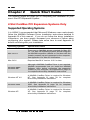
3&,([SDQVLRQ6\VWHP 8VHU V0DQXDO 6ORW6HULHV 9918 Via Pasar San Diego, CA 92126 Phone (858) 530-2511 Fax (858) 530-2733 www.magma.com [email protected] [email protected] Copyright © 2003 MAGMA This publication is protected by Federal Copyright Law, with all rights reserved. No part of this publication may be copied, photocopied, reproduced, stored in a retrieval system, translated, transmitted or transcribed, in any form or by any means manual, electric, electronic, electro-magnetic, mechanical, optical or otherwise, in whole or in part without prior written consent from MAGMA. Limitation of Liability Information presented by MAGMA in this manual is believed to be accurate and reliable. However, MAGMA assumes no responsibility for its use. No license is granted by implication or otherwise to any rights of MAGMA. Product specifications and prices are subject to change without notice. Trademark References Trademarks and registered trademarks are proprietary to their respective manufacturers. 0$*0$ 7DEOHRI&RQWHQWV PREFACE IV Advisories iv Safety Instructions v When Working Inside a Computer Protecting Against Electrostatic Discharge Regulatory Compliance Statements FCC Class A Notice CE Certification v vi viii viii viii Declaration of Conformity ix Quality & Service x Product Warranty 30 Day Money Back Guarantee Free Technical Assistance Warranty & Repair in Seven Days Returns for Repair/Replacement/Credit Out of Warranty Repair Advanced Replacement Service CHAPTER 1 INTRODUCTION x x x x x xi xi 1 The 4 Slot Desktop/Rack-mount PCI Expansion System 1 Pre-Installation Information 1 Parts List 2 Tools Required for Installation 3 CHAPTER 2 4 QUICK START GUIDE 4 Slot CardBus PCI Expansion Systems Only Supported Operating Systems Step One: Remove PCI Expansion System Cover Step Two: Install PCI Cards in PCI Expansion System Step Three: Attach PCI Expansion Cable Step Four: Install the CardBus Host Interface Card Step Five: Recheck Installation Step Six: Power Sequence Powering Up: Powering Down: Step Seven: Install Software Drivers Mac OS 9.x or Mac OS X Windows 98SE & Windows ME Windows NT, Windows 2000 & Windows XP Step Eight: System Should Be Up and Running 6ORW 6HULHV 8VHU V 0DQXDO 4 4 5 5 7 7 8 8 8 8 9 9 9 9 10 L 0$*0$ Step Nine: Finishing Touches 4 Slot PCI to PCI Expansion Systems Only: Step One: Remove PCI Expansion System Cover Step Two: Power Down Host Computer and Remove Cover Step Three: Remove PCI Cards from Host Computer Step Four: Install PCI Host Interface Card Step Five: Install PCI Cards in PCI Expansion System Step Six: Attach PCI Expansion Cable Step Seven: Recheck Installation Step Eight: Power Sequence Powering Up: Powering Down: Step Nine: System Should Be Up and Running Step Ten: Finishing Touches CHAPTER 3 BUS HIERARCHY Bus Hierarchy CHAPTER 4 10 11 11 11 12 12 13 14 14 14 15 15 15 16 17 17 ADVANCED INSTALLATION GUIDE 18 Installation Notes 18 Multiple PCI Expansion System Configurations 18 Daisy-Chaining Fan-Out 18 19 PCI Card Conflicts 20 Console Firmware Issues 20 CHAPTER 5 22 HOW TO GET MORE HELP Contacting Technical Support 22 Frequently Asked Questions 22 Returning Merchandise to MAGMA 22 APPENDIX A 24 MAC OS 9 VERIFICATION MagmaSlots APPENDIX B 24 WINDOWS DRIVER INSTALLATION 26 Applies to CB4 Series Models Only 26 Windows 98SE and Windows ME Instructions 26 Verify Installation 28 Windows NT Instructions 29 LL 6ORW 6HULHV 8VHU V 0DQXDO 0$*0$ Special Instructions for Windows NT Service Pack 6 Verify Installation Windows 2000 Instructions 30 33 34 Verify Installation 36 Windows XP Instructions 37 Verify Installation 40 How to Uninstall the MAGMA CardBus Driver Windows 98SE, Windows ME, Windows NT Windows 2000 and Windows XP PCIScope 41 41 42 43 APPENDIX C DIGIDESIGN® PRO TOOLS 45 APPENDIX D PCI-BASED SUN WORKSTATION GUIDE 46 Introduction 46 Requirements 46 Installation 46 Sample Configuration 46 6ORW 6HULHV 8VHU V 0DQXDO L LL 0$*0$ 3UHIDFH Advisories Three types of advisories are used throughout this manual to provide helpful information or to alert you to the potential for hardware damage or personal injury. They are Notes, Cautions, and Warnings. The following is an example of each type of advisory. Use caution when servicing any electrical component. NOTE An amplifying or explanatory comment related to procedural steps or text. CAUTION Used to indicate and prevent the following procedure or step from causing damage to the equipment. WARNING Used to indicate and prevent the following step from causing injury. Disclaimer: We have tried to identify all situations that may pose a warning or caution condition in this manual. However, MAGMA does not claim to have covered all situations that might require the use of a Caution or Warning. Y LY L 6ORW 6HULHV 8VHU V 0DQXDO 0$*0$ Safety Instructions Before handling the MAGMA PCI Expansion System, read the following instructions and safety guidelines to prevent damage to the product and to ensure your own personal safety. Refer to the “Advisories” section for advisory conventions used in this manual, including the distinction between Warnings, Cautions, and Notes. ♦ Always use caution when handling/operating the computer. Only qualified, experienced, authorized electronics personnel should access the interior of the computer. The power supplies produce high voltages and energy hazards, which can cause bodily harm. ♦ Use extreme caution when installing or removing components. Refer to the installation instructions in this manual for precautions and procedures. If you have any questions, please contact MAGMA Technical Support. WARNING High voltages are present inside the chassis when the unit’s power cord is plugged into and electrical outlet. Disconnect the power cord from its source before removing the chassis cover. Turning off the power switch does not remove power to components. Never modify or remove the radio frequency interference shielding from your workstation or expansion unit. To do so may cause your installation to produce emissions that could interfere with other electronic equipment in the area of your system. When Working Inside a Computer Before taking covers off a computer, perform the following steps: 1. Turn off the computer and any peripherals 2. Disconnect the computer and peripherals from their power sources to prevent electric shock or system board damage. 3. Follow the guidelines provided in “Regulatory Compliance Statements” on the following page. 4. Disconnect any telephone or telecommunications lines from the computer. 6ORW 6HULHV 8VHU V 0DQXDO ; 0$*0$ In addition, take note of these safety guidelines when appropriate: ♦ To help avoid possible damage to systems boards, wait five seconds after turning off the computer before removing a component, removing a system board, or disconnecting a peripheral device from the computer. ♦ When you disconnect a cable, pull on its connector or on its strain-relief loop, not on the cable itself. Some cables have a connector with locking tabs. If you are disconnecting this type of cable, press in on the locking tabs before disconnecting the cable. As you pull connectors apart, keep them evenly aligned to avoid bending any connector pins. Also, before connecting a cable, make sure both connectors are correctly oriented and aligned. CAUTION Do not attempt to service the system yourself except as explained in this manual. Follow installation instructions closely. . Protecting Against Electrostatic Discharge Electrostatic Discharge (ESD) Warning Electrostatic Discharge (ESD) is the enemy of semiconductor devices. You should always take precautions to eliminate any electrostatic charge from your body and clothing before touching any semiconductor device or card by using an electrostatic wrist strap and/or rubber mat. Static electricity can harm system boards. Perform service at an ESD workstation and follow proper ESD procedure to reduce the risk of damage to components. MAGMA strongly encourages you to follow proper ESD procedure, which can include wrist straps and smocks, when servicing equipment. You can also take the following steps to prevent damage from electrostatic discharge (ESD): ♦ ;YLL When unpacking a static-sensitive component from its shipping carton, do not remove the component’s anti-static packaging material until you are ready to install the component in a computer. Just before unwrapping the anti-static packaging, be sure you are at an ESD workstation or grounded. 6ORW 6HULHV 8VHU V 0DQXDO 0$*0$ ♦ When transporting a sensitive component, first place it in an anti-static container or packaging. ♦ Handle all sensitive components at an ESD workstation. possible, use anti-static floor pads and workbench pads. ♦ Handle components and boards with care. Don’t touch the components or contacts on a board. Hold a board by its edges or by its metal mounting bracket. 6ORW 6HULHV 8VHU V 0DQXDO If ;YLL LL 0$*0$ Regulatory Compliance Statements This section provides the FCC compliance statement for Class A devices and describes how to keep the system CE complaint. The Following Information is Required by the FCC FCC Class A Notice If your system is FCC Class A, the following applies: Note - This equipment has been tested and found to comply with the limits for a Class A digital device, pursuant to Part 15 of the FCC Rules. These limits are designed to provide reasonable protection against harmful interference when the equipment is operated in a commercial environment. This equipment generates, uses and can radiate radio frequency energy and, if not installed and used in accordance with the instruction manual, may cause harmful interference in which case the user will be required to correct the interference at his own expense. This device complies with Part 15 of the FCC Rules. Operation is subject to the following two conditions: (1) this device may not cause harmful interference, and (2) this device must accept any interference received including interference that may cause undesired operation. Changes or modifications not expressly approved by the party responsible for compliance could void the user’s authority to operate the equipment. NOTE The assembler of a personal computer system may be required to test the system and/or make necessary modifications if a system is found to cause harmful interferences or to be noncompliant with the appropriate standards for its intended use. CE Certification The product(s) described in this manual complies with all applicable European Union (CE) directives. For computer systems to remain CE complaint, only CE-complaint parts may be used. Maintaining CE compliance also requires proper cable and cabling techniques. MAGMA will not retest or recertify systems or components that have been reconfigured by customers. ;YLLL LLL 6ORW 6HULHV 8VHU V 0DQXDO 0$*0$ Declaration of Conformity Manufacturer’s Name: Manufacturer’s Address: MAGMA, Inc. A Mobility Electronics, Inc., Company 9918 Via Pasar San Diego, CA 92126 USA Declares that the product: Computer Peripheral Equipment Type of Equipment: Product Name: MAGMA PCI Expansion System CB4DR, CB4DRC1.5, CB4DRQ, CB4DRQC1.5, PCI4DR, Model Number: PCI4DRC1.5, PCI4DR2, PCI4DR2C1.5, PCI4DRQ, PCI4DRQC1.5 to which this declaration relates, meet the essential health and safety requirements and is in conformity with the relevant EU Directives listed below: EU EMC Directive 89/336/EEC EU Low Voltage Directive 73/23/EEC EN 55022:1998/A1:2000; CISPR 22:1997/A1:2000 Class A, Limits and Methods of Measurement of Radio Disturbance Characteristics of Information Technology Equipment EN 61000-3-2:1995 Power Frequency Emission for AC Main Harmonics (Not Applicable for units under 75 Watts) EN 61000-3-3:1995 Voltage Fluctuations (Not Applicable for units under 75 Watts) EN 50024:1998 Immunity, ITE Requirements -EN 61000-4-2 Electrostatic Discharge (ESD) Immunity (Supersedes IEC 801-2) -EN 61000-4-3 (Formerly ENV 50140) Radiated RF Field Immunity (Supersedes IEC 801-3 & IEC 1000-4-3) -EN 61000-4-4 EFT Immunity for AC and I/O Lines (Supersedes IEC 801-4) -EN 61000-4-5 Surge (Line-Ground & Line-Line) Immunity -EN 61000-4-6 (Formerly ENV 50141) Conducted Radio Field (Common Mode) Immunity -EN 61000-4-8 Power Frequency Magnetic Field Immunity -EN 61000-4-11 Voltage Dip/Surge Immunity EN 60950:2000 Safety of Information Technology Equipment (ITE) for CE certification The technical documentation required to demonstrate the above products meet the requirements of the EMC Directive and Low Voltage Directive has been compiled by MAGMA and is available for inspection by the relevant enforcement authorities. signed Nancy Rubinstein General Manager San Diego, CA March 15, 2002 A signed original copy of this document is available from MAGMA. 6ORW 6HULHV 8VHU V 0DQXDO [ L[ L 0$*0$ Quality & Service Product Warranty MAGMA PCI Expansion Systems carry a one-year warranty against defects in materials or workmanship from the date of shipment to the original purchaser. Any products found to be defective in material or workmanship will be repaired or replaced promptly. Please Note: Products that have been modified will not be covered under this warranty. 30 Day Money Back Guarantee Any single standard MAGMA manufactured product may be returned within 30 days of purchase for a full refund of the price paid for the product being returned (must be in new condition in the original packaging). If you are not satisfied, or chose the wrong product by mistake, you do not have to keep it. Please call our Sales Group for a Return Merchandise Authorization number before returning the product. Free Technical Assistance MAGMA is dedicated to providing competent, responsive technical support both before and after the sale. We have staffed our support department with professional software and hardware engineers and given them the finest tools. MAGMA provides unlimited support to all customers for the life of all products purchased. Warranty & Repair in Seven Days Any MAGMA manufactured product returned for repair under warranty will be repaired and shipped within one week unless it is necessary for a Technical Support Engineer to contact you and discuss the repair. Repaired products are returned by the same shipping method as they are received. Please call for a Return Merchandise Authorization number before returning the product. Please Note: All returns to MAGMA for Repair/Replacement/Credit must be shipped back to MAGMA with all Shipping Charges and Duties Paid. Shipments that arrive with freight or duties due, or returned collect, will be refused and sent back to the sender at their own expense. Returns for Repair/Replacement/Credit It is not required, though highly recommended, that you keep the packaging from the original shipment of your MAGMA Product. However, if you return a product to MAGMA for warranty repair/replacement or take advantage of the 30 day money back guarantee, you will need to package the product in a manner similar to [ 6ORW 6HULHV 8VHU V 0DQXDO 0$*0$ the manner in which it was received from our plant. MAGMA cannot be responsible for any physical damage to the product or component pieces of the product (such as the host or expansion interfaces for PCI expansion systems) that are damaged due to inadequate packing. Physical damage sustained in such a situation will be repaired at the owner's expense in accordance with Out of Warranty Procedures. Please, protect your investment, a bit more padding in a good box will go a long way to insuring the device is returned to us in the same condition you shipped it in. Please call for a Return Merchandise Authorization number before returning the product. Out of Warranty Repair Any out of warranty MAGMA manufactured product can be repaired at the cost of MAGMA parts, plus current labor rate (not to exceed 50% off the current list price for the same or equivalent product) plus freight. Please call for a Return Merchandise Authorization number before returning the product. There will be a minimum charge for 1 hour's labor for evaluation of the product/unit. If repairs are needed, this will be applied to the repair of the product. Once evaluation has been completed, a Customer Support Representative will contact you with any options you may have and to authorize the repair work before the repair is performed. Advanced Replacement Service This Fee Based Service is primarily geared towards correcting severe problems encountered in a system within the first 90 days after shipment from the factory, but it is also available, on a graduated fee scale during the term of the Warranty Period. Under the terms of this Service, MAGMA will replace a warranted MAGMA manufactured product prior to receiving the defective product from the customer. Advanced replacements are available upon credit approval or by providing a VISA, MasterCard or American Express card number as security for the returned product. The cost for this service is the appropriate, graduated fee for Advanced non-refundable, Replacement, as detailed in the chart below, plus freight. PRODUCT PCI Expansion System PCI Expansion Boards 300/400W Power Supply Other Power Supply Any Product under $50.00 0-90 days $150.00 $50.00 $50.00 $25.00 $25.00 TIME OWNED 91 days - 6 mos. $300.00 $100.00 $100.00 $50.00 $25.00 6 mos. – 1 yr $450.00 $150.00 $150.00 $75.00 $25.00 Please Note: This fee schedule subject to change. For current information consult your Technical Support Engineer at the time of the request.The item must be returned to MAGMA with all parts and components that were shipped with it, in undamaged condition. The Customer shall be responsible for missing components and/or systems or components that are returned and are found to be physically damaged. 6ORW 6HULHV 8VHU V 0DQXDO [[LL 0$*0$ Non-Returned Advanced Replacements: Advanced Replacements that are not returned within 30 days of replacement shipment will automatically be charged to the securing credit card. If the product is returned after the credit card is charged, the entity (person or company) will be responsible for a Restocking Fee. This fee will be 25% of the listed price of the replaced unit, with a minimum Restocking Fee of $25.00. Product will only be accepted for return and restocking if the Advanced Replacement is less than 90 days from date of replacement unit shipment. [[LLLL 6ORW 6HULHV 8VHU V 0DQXDO 0$*0$ &KDSWHU,QWURGXFWLRQ The 4 Slot Desktop/Rack-mount PCI Expansion System MAGMA's 4 Slot PCI Expansion System is a general-purpose bus expansion system for the Peripheral Component Interconnect (PCI) local bus. The expansion bus is fully compliant with the PCI Local Bus Specification. The PCI expansion system consists of a PCI host interface card, an expansion bus cable (a shielded, high-speed cable), an expansion motherboard and a desktop/rack-mount enclosure with a power supply. MAGMA CardBus PCI Expansion Systems are configured to operate with PC Laptops and Apple PowerBooks, and include a CardBus host interface card, rather than the PCI host interface card. S S Enclosure: Dimensions: S S S Weight: Construction: Cooling: S S Motherboard: Power Supply: S S S Standard Cable: Disk Drive Brackets: PCI Bus: Environment: S Certifications: S S S Warranty: Options: Approvals S Desktop/Rack-mount 13.1"W x 3.5"H x 16.4"D with rack-mount ears: 19”W x 3.5”H x 16.4”D (2U high) 9 lb or 4.086 kg Aluminum One or Two 30 CFM Fan or Two 28 CFM in “Quiet” version 4 PCI Slots (supports full or short-length PCI cards) Input 90/240 VAC 50-60Hz (Auto Select) 275W “Quiet” ATX or 300W ATX 1-meter One half-height 5.25” (front accessible) Two 3.5” (internal) 32 bits/33 MHz 0° to 50° C Operating Temperature -20° to 60° C Storage Temperature 5% to 85% Relative Humidity, Non-condensing FCC Class A Approved CE Compliance 1 Year Return to Factory 1.5-meter cable Digidesign Sonic Solutions Pre-Installation Information Before using the 4 Slot PCI Expansion System you should perform the following steps: • Inventory the shipping carton contents for all of the required parts • Gather all of the necessary tools required for installation, and finally • Read this manual 6ORW 6HULHV 8VHU V 0DQXDO 0$*0$ Follow these suggested guidelines and cautions while setting up your PCI Expansion System: • Only use the interface cable provided by MAGMA • Use keyed connectors (to prevent attaching a cable backwards) • Be careful when routing signal cables to your devices • Avoid sharp bends or folds in the signal cable • Provide enough slack to allow easy device placement • Beware of sources of scuffing and abrasion damage to the cables • Secure the devices in their shelves using the appropriate hardware, and finally • Use the screws or brackets supplied with the device (suitable mounting brackets, adapters, and hardware are available from your local computer dealer or retailer) Parts List The following parts are provided: Qty Item 1 Desktop enclosure containing a 4 slot PCI expansion motherboard, an auto-switching power supply (275W or 300W) and mounting brackets for four disk drives. PCI expansion cable (1-meter or 1.5-meter) PCI host interface card or CardBus Host Interface Card Power supply cord Rack-mount flanges and screws Rubber feet User’s Manual CardBus PCI Drivers & Utilities CD (CardBus CD)- included with CardBus systems only 1 1 1 2 4 1 1 NOTE The PCI Expansion System is shipped with some parts packaged in a separate box within the larger box that the chassis is shipped in. 6ORW 6HULHV 8VHU V 0DQXDO 0$*0$ Tools Required for Installation In order to complete the installation of the PCI expansion system you will need the following tools: • • A suitable Electrostatic Discharge Protective environment One Phillips-head screwdriver 6ORW 6HULHV 8VHU V 0DQXDO 0$*0$ &KDSWHU4XLFN6WDUW*XLGH The following steps will guide you in completing the installation of your new 4 Slot PCI Expansion System. 4 Slot CardBus PCI Expansion Systems Only Supported Operating Systems It is HIGHLY recommended that Microsoft Windows users meticulously follow the MAGMA Software Driver Installation instructions detailed in Appendix B of this manual. If you do not follow the driver installation instructions, you have greatly increased your chances of failure when configuring your system. Please take some time to read Appendix B before continuing with your installation. Operating Systems Special Instructions Mac OS 9.x There are no MAGMA drivers required for Mac OS 9.x. The Mac OS operating system should recognize the MAGMA expansion chassis on first boot with the chassis powered up and connected to the computer. See Appendix A for Mac OS Verification. Mac OS X Requires MacOS X Version 10.2.2 or later Windows 98SE Windows ME Although a MAGMA CardBus Driver is not required, MAGMA recommends that you install the MAGMA Software Utility before connecting the expansion chassis to your computer. See Appendix B, page 26 for complete driver/utility installation instructions. Windows NT 4.0 A MAGMA CardBus Driver is required for Windows NT. See Appendix B, page 29 for complete driver/utility installation instructions. Windows 2000 A MAGMA CardBus Driver is required for Windows 2000. See Appendix B, page 34 for complete driver/utility installation instructions. Windows XP A MAGMA CardBus Driver is required for Windows XP. See Appendix B, page 37 for complete driver/utility installation instructions. 6ORW 6HULHV 8VHU V 0DQXDO 0$*0$ Step One: Remove PCI Expansion System Cover WARNING High voltages are present inside the chassis when the unit’s power cord is plugged into an electrical outlet. Disconnect the power cord from its source before removing the chassis cover. Turning the system power off at the power on/off switch does not remove power to components. High voltage is still present. CAUTION Before touching anything inside the chassis, move to an ESD station and follow proper ESD procedure. Failure to do so may result in electrostatic discharge damaging the computer or its components. For more information, see “Protecting Against Electrostatic Discharge”. Seven screws retain the cover on the 4 Slot chassis. They are located on the rear of the unit, one on the left, right and top center of the cover's back edge and two on each side of the unit that are used when attaching the rack-mount ears. Remove these screws to open the chassis. Disengage the cover from the guides at the front of the chassis by firmly grasping the sides of the cover and pulling upward to lift the cover off the chassis. CAUTION When replacing the cover, be sure that the front edge guides on the enclosure cover engage the inner lip of the expansion chassis. Step Two: Install PCI Cards in PCI Expansion System WARNING High voltages are present inside the chassis when the unit’s power cord is plugged into an electrical outlet. Disconnect the power cord from its source before removing the chassis cover. Turning the system power off at the power on/off switch does not remove power to components. High voltage is still present. 6ORW 6HULHV 8VHU V 0DQXDO 0$*0$ Electrostatic Discharge (ESD) Warning All PCI cards are susceptible to electrostatic discharge. When moving PCI cards, it is best to carry the cards in anti-static packaging. If you need to set a PCI card down, be sure to place it inside or on top of an anti-static surface. For more information, see “Protecting Against Electrostatic Discharge”. Generally, when installing PCI cards in the expansion system, it should make no difference what slot order you place your cards in, unless specified by the PCI card manufacturer. Slot ordering in the 4 Slot CardBus PCI Expansion System should begin with the bottom slot – labeled Slot 4. Install PCI cards following PCI card manufacturer’s recommendations. Be sure to secure cards using bracket screws. Also check to make sure PCI card inserted is not touching any components or metal chassis. CAUTION Take care when routing cables within the PCI expansion system in order to avoid damaging the signal cables (especially unshielded flat ribbon cables) or the power cables for internally installed devices. Be sure to leave enough "slack" in the cables to allow you to easily remove them if necessary to service the device(s). NOTE Make sure that all PCI cards are fully seated in their connectors. When correctly seated in its connector, you will notice a firm resistance when you pull up gently on the card. To keep the cards in place, secure them in the chassis with their retaining screws (supplied with the PCI Expansion System). The sheer number of PCI cards and device drivers available makes it impossible for MAGMA to fully test and certify all available PCI cards for use in the PCI expansion system. Our best advice to you in this regard is to insist on full PCI Specification compliance from your card and system vendors. Cards and systems should be at least PCI Specification Revision 2.0 compliant with 2.1 compliance recommended. Compliance in your system motherboard, PCI cards and console firmware (or BIOS) is your best assurance that everything will install and operate smoothly. 6ORW 6HULHV 8VHU V 0DQXDO 0$*0$ NOTE Not all PCI cards are as "well-behaved" as they should be. Sometimes simply moving a PCI card that is having a problem to a different slot, or reordering your cards in their slots, may alleviate "behavior" problems. Step Three: Attach PCI Expansion Cable Carefully position the PCI Expansion System so that the supplied expansion cable will conveniently reach from the connector of the CardBus Card to the connector of the 4 Slot chassis. Attach one end of the PCI Expansion Cable to the CardBus Card and secure it using the captive thumbscrews on the cable. Carefully route the cable to the 4 Slot chassis and secure it with the captive thumbscrews. It is important that the cable be attached securely to the card connectors at both ends. Step Four: Install the CardBus Host Interface Card NOTE CardBus PC Cards can only be used in systems that support CardBus. A special keying mechanism prevents insertion in systems that do not support 32-bit CardBus PC cards. 1. Begin installation of your CardBus Host Interface Card by first powering down your laptop computer. Use the procedures for shutting down your operating system and shutting off power to your system provided in your owner’s manual or system documentation. 2. Insert the CardBus Host Interface Card with the MAGMA logo side up, (gold strip up) into the PC Card slot. Gently push the card until it is seated firmly. NOTE If your computer has two CardBus (or PC Cards) slots, MAGMA recommends that you install the MAGMA CardBus card into Socket 2. 3. For more information on using CardBus PC cards, please refer to your computer’s user manual or system documentation. 6ORW 6HULHV 8VHU V 0DQXDO 0$*0$ Step Five: Recheck Installation Check your installation before powering up the 4 Slot CardBus PCI Expansion System for the first time. Although the power supply has an over voltage protection device built into it, it may not "trip" in time to fully protect a device that has been improperly connected or whose power cable has been damaged. Step Six: Power Sequence NOTE If at all possible, plug the power cords from the PCI Expansion System and your host computer into a shared power strip, preferably one that has surge and noise suppression circuitry built into it. NOTE The “Quiet” 275-watt and the 300-watt power supplies are auto switching, which means the power supply will automatically adjust to the voltage required for the region you are in. Powering Up: You must apply power to the PCI Expansion System first and then power up your host computer. This will allow the higher numbered PCI buses in your hierarchy to be at a stable state at the time that the host system issues its master power-on bus reset. In systems that perform automatic PCI bus configuration, this will allow the configuration code to recognize the PCI bus hierarchy and the attached devices. If you have several PCI Expansion Systems in your configuration, you should power up the most "downstream" expansion system first, then each expansion system moving “upstream” and finally the host system last. Powering Down: It is recommended that you first shut down the host computer correctly and then power down the chassis to avoid ‘computer lock-up’. 6ORW 6HULHV 8VHU V 0DQXDO 0$*0$ Step Seven: Install Software Drivers WARNING You WILL be prompted to Shut Down and Reboot your system several times during software installation. Please be patient, each Shut Down and Reboot does serve a purpose and is required for correct installation. If you Shut Down and Reboot when requested, it may save you from having to make a call to MAGMA Technical Support. Mac OS 9.x or Mac OS X If you are running Mac OS, you may skip this step and continue to Step Eight. There are no MAGMA drivers required for Mac OS 9.x or Mac OS X. The Mac OS operating system should recognize the MAGMA expansion chassis on first boot with the chassis powered up and connected to the PowerBook. See Appendix A for Mac OS 9 Verification Instructions. Windows 98SE & Windows ME Although a MAGMA CardBus Driver is not required, MAGMA recommends that you install the MAGMA Software Utility before connecting the expansion chassis to your computer. See Appendix B, page 26 for complete MAGMA Software installation instructions. If you did not realize that you should have loaded the MAGMA CardBus Driver already, it’s okay. Since a MAGMA CardBus Driver is not required, you may be prompted to locate and load drivers for PCI cards that you have installed in the chassis at this time. If you are prompted to reboot, please do so to ensure correct installation. After installation of other drivers is complete, you should load the MAGMA CardBus Driver following the Windows 98SE/ME Instructions detailed in Appendix B of this manual. Windows NT, Windows 2000 & Windows XP A MAGMA CardBus Driver is required for Windows NT, Windows 2000 and Windows XP. See Appendix B for complete driver installation instructions before continuing to Step Eight. NOTE It is HIGHLY recommended that Microsoft Windows users meticulously follow the MAGMA Software Driver Installation instructions detailed in Appendix B of this manual. If you do not follow the driver installation instructions, you have greatly increased your chances of failure when configuring your system. 6ORW 6HULHV 8VHU V 0DQXDO 0$*0$ Step Eight: System Should Be Up and Running WARNING High voltages are present inside the chassis when the unit’s power cord is plugged into an electrical outlet. Disconnect the power cord from its source before replacing the chassis cover. Turning the system power off at the power on/off switch does not remove power to components. High voltage is still present. CAUTION Before touching anything inside the chassis, move to an ESD station and follow proper ESD procedure. Failure to do so may result in electrostatic discharge damaging the computer or its components. For more information, see “Protecting Against Electrostatic Discharge”. If there is a problem, be sure to turn off the power before making any changes. If you are having trouble with the system, turn off the host computer and the chassis, then check that all cards are seated properly and all cables are connected. If you are still having problems, contact MAGMA Technical Support for more help. Step Nine: Finishing Touches WARNING High voltages are present inside the chassis when the unit’s power cord is plugged into an electrical outlet. Disconnect the power cord from its source before replacing the chassis cover. Turning the system power off at the power on/off switch does not remove power to components. High voltage is still present. CAUTION Before touching anything inside the chassis, move to an ESD station and follow proper ESD procedure. Failure to do so may result in electrostatic discharge damaging the computer or its components. For more information, see “Protecting Against Electrostatic Discharge”. After your system is working properly, replace any empty slots with slot covers, and replace the host computer cover and expansion chassis cover. 6ORW 6HULHV 8VHU V 0DQXDO 0$*0$ 4 Slot PCI to PCI Expansion Systems Only: Step One: Remove PCI Expansion System Cover WARNING High voltages are present inside the chassis when the unit’s power cord is plugged into an electrical outlet. Disconnect the power cord from its source before removing the chassis cover. Turning the system power off at the power on/off switch does not remove power to components. High voltage is still present. CAUTION Before touching anything inside the chassis, move to an ESD station and follow proper ESD procedure. Failure to do so may result in electrostatic discharge damaging the computer or its components. For more information, see “Protecting Against Electrostatic Discharge”. Seven screws retain the cover on the 4 Slot chassis. They are located on the rear of the unit, one on the left, right and top center of the cover's back edge and two on each side of the unit that are used when attaching the rack-mount ears. Remove these screws to open the chassis. Disengage the cover from the guides at the front of the chassis by firmly grasping the sides of the cover and pulling upward to lift the cover off the chassis. CAUTION When replacing the cover, be sure that the front edge guides on the enclosure cover engage the inner lip of the expansion chassis. Step Two: Power Down Host Computer and Remove Cover WARNING High voltages are present inside the chassis when the unit’s power cord is plugged into an electrical outlet. Disconnect the power cord from its source before removing the chassis cover. Turning the system power off at the power on/off switch does not remove power to components. High voltage is still present. 6ORW 6HULHV 8VHU V 0DQXDO 0$*0$ CAUTION Before touching anything inside the chassis, move to an ESD station and follow proper ESD procedure. Failure to do so may result in electrostatic discharge damaging the computer or its components. For more information, see “Protecting Against Electrostatic Discharge”. Use the procedures for shutting down your system provided in your owner's manual or system documentation. Turn off power to your computer, but DO NOT unplug the power cord from the power receptacle. Touch the metal case on your computer to discharge any built up static electricity. Remove the cover. Step Three: Remove PCI Cards from Host Computer Electrostatic Discharge (ESD) Warning All PCI cards are susceptible to electrostatic discharge. When moving PCI cards, it is best to carry the cards in anti-static packaging. If you need to set a PCI card down, be sure to place it inside or on top of an anti-static surface. For more information, see “Protecting Against Electrostatic Discharge”. Remove any PCI cards from your host system that you wish to relocate to the PCI expansion system. Step Four: Install PCI Host Interface Card Install the PCI host interface card in any available PCI slot in your host computer and secure with a retaining screw. The PCI Host Interface Card is a standard "short" universal PCI adapter card. Install it in your host computer (or an "upstream" PCI Expansion System), by inserting the card into any available PCI slot and securing it with a retaining screw. NOTE Some applications require that the PCI Host Interface Card be installed in a specific slot in the host computer. For more information, please contact the MAGMA Technical Support Department. 6ORW 6HULHV 8VHU V 0DQXDO 0$*0$ Step Five: Install PCI Cards in PCI Expansion System WARNING High voltages are present inside the chassis when the unit’s power cord is plugged into an electrical outlet. Disconnect the power cord from its source before removing the chassis cover. Turning the system power off at the power on/off switch does not remove power to components. High voltage is still present. Electrostatic Discharge (ESD) Warning All PCI cards are susceptible to electrostatic discharge. When moving PCI cards, it is best to carry the cards in anti-static packaging. If you need to set a PCI card down, be sure to place it inside or on top of an anti-static surface. For more information, see “Protecting Against Electrostatic Discharge”. Generally, when installing PCI cards in the expansion system, it should make no difference what slot order you place your cards in, unless specified by the PCI card manufacturer. Slot ordering in the 4 Slot PCI to PCI Expansion System should begin with the bottom slot – labeled Slot 4. Install PCI cards, following PCI card manufacturer’s recommendations. Be sure to secure cards using bracket screws. Also check to make sure PCI card inserted is not touching any components or metal chassis. CAUTION Take care when routing cables within the PCI expansion system in order to avoid damaging the signal cables (especially unshielded flat ribbon cables) or the power cables for internally installed devices. Be sure to leave enough "slack" in the cables to allow you to easily remove them if necessary to service the device(s). NOTE Make sure that all PCI cards are fully seated in their connectors. When correctly seated in its connector, you will notice a firm resistance when you pull up gently on the card. To keep the cards in place, secure them in the chassis with their retaining screws (supplied with the PCI Expansion System). The sheer number of PCI cards and device drivers available makes it impossible for MAGMA to fully test and certify all available PCI cards for 6ORW 6HULHV 8VHU V 0DQXDO 0$*0$ use in the PCI expansion system. Our best advice to you in this regard is to insist on full PCI Specification compliance from your card and system vendors. Cards and systems should be at least PCI Specification Revision 2.0 compliant with 2.1 compliance recommended. Compliance in your system motherboard, PCI cards and console firmware (or BIOS) is your best assurance that everything will install and operate smoothly. NOTE Not all PCI cards are as "well-behaved" as they should be. Sometimes simply moving a PCI card that is having a problem to a different slot, or reordering your cards in their slots, will alleviate "behavior" problems. Step Six: Attach PCI Expansion Cable Carefully position the PCI Expansion System so that the supplied expansion cable will conveniently reach from the connector of the PCI Host Interface Card to the connector provided on the 4 Slot PCI Expansion System. Attach one end of the PCI Expansion Cable to the Host Interface Card and secure it using the captive thumbscrews on the cable. Carefully route the cable to the 4 Slot PCI Expansion System and secure it with the captive thumbscrews. It is important that the cable be attached securely to the card connectors at either end. Step Seven: Recheck Installation Check your installation before powering up the PCI Expansion System for the first time. Although the power supply has an over voltage protection device built into it, it may not "trip" in time to fully protect a device that has been improperly connected or whose power cable has been damaged. Step Eight: Power Sequence NOTE If at all possible, plug the power cords from the PCI Expansion System and your host computer into a shared power strip, preferably one that has surge and noise suppression circuitry built into it. 6ORW 6HULHV 8VHU V 0DQXDO 0$*0$ NOTE The “Quiet” 275-watt and the 300-watt power supplies are auto switching, which means the power supply will automatically adjust to the voltage required for the region you are in. Powering Up: You must apply power to the PCI Expansion System first and then power up your host computer. This will allow the higher numbered PCI buses in your hierarchy to be at a stable state at the time that the host system issues its master power-on bus reset. In systems that perform automatic PCI bus configuration, this will allow the configuration code to recognize the PCI bus hierarchy and the attached devices. If you have several PCI Expansion Systems in your configuration, you should power up the most "downstream" expansion system first, then each expansion system moving “upstream” and finally the host system last. Powering Down: It is recommended that your first shut down the host computer correctly and then power down the chassis to avoid ‘computer lock-up’. Step Nine: System Should Be Up and Running WARNING High voltages are present inside the chassis when the unit’s power cord is plugged into an electrical outlet. Disconnect the power cord from its source before replacing the chassis cover. Turning the system power off at the power on/off switch does not remove power to components. High voltage is still present. CAUTION Before touching anything inside the chassis, move to an ESD station and follow proper ESD procedure. Failure to do so may result in electrostatic discharge damaging the computer or its components. For more information, see “Protecting Against Electrostatic Discharge”. If there is a problem, be sure to turn off the power before making any changes. If you are having trouble with the system, turn off the host computer and the chassis, then check that all cards are seated in the slot properly and all cables are connected. 6ORW 6HULHV 8VHU V 0DQXDO 0$*0$ If you are still having problems, contact MAGMA Technical Support for more help. Step Ten: Finishing Touches WARNING High voltages are present inside the chassis when the unit’s power cord is plugged into an electrical outlet. Disconnect the power cord from its source before replacing the chassis cover. Turning the system power off at the power on/off switch does not remove power to components. High voltage is still present. CAUTION Before touching anything inside the chassis, move to an ESD station and follow proper ESD procedure. Failure to do so may result in electrostatic discharge damaging the computer or its components. For more information, see “Protecting Against Electrostatic Discharge”. After your system is working properly, replace any empty slots with slot covers, and replace the host computer cover and expansion chassis cover. 6ORW 6HULHV 8VHU V 0DQXDO 0$*0$ &KDSWHU%XV+LHUDUFK\ Bus Hierarchy The following figures are representative of the PCI Bus hierarchies for the 4 Slot CardBus and PCI to PCI Expansion Systems. These figures pictorially conveys the overall PCI bus topology of the system. The key point in the following figure of the 4 Slot Topology is the connecting cable between the Host Interface Card and the Expansion Interface is actually a PCI bus itself. In general, we do not know what the actual Bus numbers are. We only know how they increment starting from the MAGMA PCI Host Interface. 4 Slot Topology NOTE All PCI cards installed in the 4 Slot PCI to PCI Expansion Systems will appear on PCI Bus 2. In Apple G4s, Bus 0 is internal; so all Busses are incremented by 1. All PCI Cards installed in the 4 Slot CardBus PCI Expansion System will appear on Bus 3. In laptop computers, the CardBus slot is Bus 1, so all Busses are incremented by 1. 6ORW 6HULHV 8VHU V 0DQXDO 0$*0$ &KDSWHU$GYDQFHG,QVWDOODWLRQ *XLGH Installation Notes If at all possible, plug the power cords from the PCI expansion system and your host computer into a shared power strip, preferably one that has surge and noise suppression circuitry built into it. Make sure that all PCI cards are fully seated in their connectors. When correctly seated in its connector, you will notice a firm resistance when you pull up gently on the card. To keep the cards in place, secure them in the chassis with their retaining screws (supplied with your PCI Expansion System and your host computer). Multiple PCI Expansion System Configurations The PCI Local Bus Specification defines the PCI bus as a hierarchical bus where PCI to PCI Bridges (PPBs) may be used to add "levels" to the PCI bus hierarchy. You can easily add two or more PCI expansion systems to your configuration in either a "daisy-chain" or "fan-out" configuration. Each of these configurations has advantages and uses. Daisy-Chaining In the daisy-chain configuration, successive PCI expansion systems are added to the "end" of the PCI bus hierarchy, which adds "depth" to the PCI Local Bus by increasing the number of PCI Local Bus levels active in the system configuration. Daisy-Chain Configuration If we attach a new motherboard at the end of the bus hierarchy we would have a system configuration as depicted in the following drawing. 6ORW 6HULHV 8VHU V 0DQXDO 0$*0$ Extended Daisy-Chain Configuration In this case, the bus labeled (Bus 6) is obviously further downstream (hierarchically speaking) than the bus labeled (Bus 4). And, of course, there is a caveat to all of this: the bus numbering depends on the algorithm implemented by your BIOS or console firmware configuration code. We have labeled everything here as if: a) The BIOS or firmware runs a true "depth-first" search of the PCI bus hierarchy b) Your BIOS or firmware will actually deal with multiple PPBs Fan-Out In a fan-out configuration, successive PCI expansion systems are added to the PCI bus hierarchy at a "peer" level of other existing expansion buses, thus adding "breadth" to the PCI bus hierarchy since these buses will be at the same hierarchical level within the system configuration. Fan-Out Configuration The PCI Local Bus in your host computer will typically be numbered as "PCI Bus Zero". Each addition of a PPB to the bus hierarchy will add a new bus level into the hierarchy. In the following discussion, higher PCI Local Bus numbers are termed to be "downstream" of lower numbered 6ORW 6HULHV 8VHU V 0DQXDO 0$*0$ buses. Similarly, lower numbered buses are termed to be "upstream" of higher numbered buses. Each PPB has a primary side (which is attached to the "upstream" or lower numbered PCI bus), and a secondary side (which is attached to the "downstream" or higher numbered PCI bus). In the case of the MAGMA PCI Expansion System, the PCI host interface card, which is plugged into an available slot on your host computer, has at its "upstream" side (Bus 0) and at its "downstream" side the cable (Bus 1). The PCI expansion interface also has a PPB on board and its "upstream" side is attached to the cable bus (Bus 1) and its "downstream" side is attached to the expansion motherboard (Bus 2). Inserting a host interface into an available slot in the motherboard results in its primary bus being at (Bus 2), its secondary bus (the cable bus) being at (Bus 3) and the PCI expansion interface in the second motherboard is (Bus 4). PCI Card Conflicts If you determine that one PCI card is interfering with the operation of another card, first try reorganizing the cards on the motherboard. Moving the cards around can change the order in which the cards are configured by the system firmware (whether console code or BIOS code) and will go a long way toward resolving module conflicts. Console Firmware Issues Different systems have different names for their console firmware. On an IBM-PC compatible the firmware is referred to as the system's "BIOS" code. For a SUN workstation the computer console code is called OBP (OpenBootProm). For a Macintosh computer the console code is called "OpenFirmware" code. Regardless of what it's called, the console firmware will perform the same basic set of functions. In a nutshell, the console firmware must provide a set of hardware or architecture-specific functions and routines that are called during the early phases of system startup. Specifically, these functions and callable routines allow the PCI devices in a host computer to be recognized and configured for use by the soon-to-be-running system. The portion of the PCI Local Bus Specification that directly addresses this class of code is the PCI BIOS Specification. A similar specification for use by systems that are not IBM-PC compatible is the IEEE 12751994 OpenFirmware Bus Binding Specification. These two different specifications are complimentary and form a consistent methodology that allows for PCI option identification and configuration during the initial phases of booting the target operating system. 6ORW 6HULHV 8VHU V 0DQXDO 0$*0$ During configuration of your system's PCI cards, the PCI bus must be probed in order to determine which, if any, PCI cards are present in your system. The probe instructions used ensure that PCI slots that contain valid cards are configured into your system in a consistent and reliable manner and that any invalid option card, or empty option slot, is ignored. In theory, the console configuration code should be able to traverse up to 255 PCI buses in your system detecting all installed cards and performing the necessary configuration processing for each discovered PCI card. Unfortunately, not all console firmware is created equal. In order to configure all of your PCI cards installed in the PCI expansion system, your console firmware must be able to traverse multiple levels of bridges. In point of fact, the 255 bus limit is a theoretical maximum with the practical limit somewhat lower (yet should still be a large number, like 100). Most modern console firmware and BIOS code allows multiple bridges (and thus PCI buses) to be correctly configured. Certain older firmware implementations, however, place an arbitrary limit on the number of bridge levels that can be traversed during power-on configuration. Your firmware should be PCI Specification 2.1 compliant in order to effectively use a MAGMA PCI Expansion System. For "fan-out" and "daisy chained" system configurations where more than one PCI expansion system is being used, you should count all of the bridge levels to your most deeply nested PCI bus to determine the maximum number of bridge levels that must be traversed. 6ORW 6HULHV 8VHU V 0DQXDO 0$*0$ &KDSWHU+RZWR*HW0RUH+HOS Contacting Technical Support For a quick response, send an email to [email protected] with a detailed description of your problem, or visit our web site at: www.magma.com/support/support.htm Our support department can also be reached by fax at (858) 530-2733 or by phone at (858) 530-2511. Support is available Monday through Friday, 8:00 AM to 5:00 PM PT. When contacting MAGMA Technical Support, please be sure to include the following information: 1) Name 2) Company Name 3) Phone Number 4) Fax Number 5) Email Address 6) MAGMA Product Name 7) MAGMA Serial Number 8) Computer Make 9) Computer Model 10) Operating System and Version 11) Description of the Problem Frequently Asked Questions You can visit the MAGMA Technical Support FAQ pages on the Internet at: www.magma.com/support/support.htm Returning Merchandise to MAGMA If factory service is required, a Service Representative will give you a Return Merchandise Authorization (RMA) number. Put this number and your return address on the shipping label when you return the item(s) MAGMA will return any product that is not for service. accompanied by an RMA number. Please note that MAGMA WILL NOT accept COD packages, so be sure to return the product freight and duties-paid. Ship the well-packaged product to the address below: MAGMA RMA # ________ 9918 Via Pasar San Diego, CA 92126 USA It is not required, though highly recommended, that you keep the packaging from the original shipment of your MAGMA product. 6ORW 6HULHV 8VHU V 0DQXDO 0$*0$ However, if you return a product to MAGMA for warranty repair/ replacement or take advantage of the 30-day money back guarantee, you will need to package the product in a manner similar to the manner in which it was received from our plant. MAGMA cannot be responsible for any physical damage to the product or component pieces of the product (such as the host or expansion interfaces for PCI expansion systems) that are damaged due to inadequate packing. Physical damage sustained in such a situation will be repaired at the owner’s expense in accordance with Out of Warranty Procedures. Please, protect your investment, a bit more padding in a good box will go a long way to insuring the device is returned to use in the same condition you shipped it in. Please call for an RMA number first. 6ORW 6HULHV 8VHU V 0DQXDO 0$*0$ $33(1',;$0DF269HULILFDWLRQ MagmaSlots MagmaSlots is a simple utility application for displaying information on PCI cards installed in the Macintosh computer. It uses the Mac OS NameRegistry to discover what slots have PCI cards in them, and then displays basic information for each card in a simple console window. MagmaSlots is included on the MAGMA CardBus CD or you can download this utility from our web site at: www.magma.com/support/support.htm. NOTE The MagmaSlots utility is currently available for Mac OS 9.x only. Connect the expansion chassis to your computer by following the Stepby-Step Instructions included in Chapter Two: Quick Start Guide. With the MAGMA expansion chassis powered up and connected to your computer, launch the MagmaSlots application by double-clicking its icon. It is recommended that you launch MagmaSlots from a location on your desktop. A console window similar to the one shown below should appear: If you see this entry, it means that your computer has recognized the MAGMA expansion chassis. 6ORW 6HULHV 8VHU V 0DQXDO 0$*0$ You should also see a separate entry for each PCI card installed in the PCI Expansion System. For example, if you have an Adaptec 2906 SCSI card installed in the chassis, you should see a console window similar to the one shown below: MAGMA expansion chassis Adaptec 2906 SCSI Controller NOTE Some PCI cards will produce multiple entries in the MagmaSlots console window. If MagmaSlots does not display some or all of the PCI cards installed in the expansion chassis, you should do the following before contacting MAGMA Technical Support: 1. 2. 3. Make sure that you apply power to the expansion chassis first, then power up the computer. Make sure the MAGMA CardBus Interface is inserted with the Gold Strip facing up. Make sure all cables are securely connected. 6ORW 6HULHV 8VHU V 0DQXDO 0$*0$ $33(1',;%:LQGRZV'ULYHU ,QVWDOODWLRQ Applies to CB4 Series Models Only The following sections will guide you through MAGMA CardBus Driver/Utility installation for each supported Windows operating system. Windows 98SE and Windows ME Instructions NOTE Under Windows 98SE and Windows ME, it is recommended that you install the MAGMA CardBus Software Utility BEFORE connecting the MAGMA expansion chassis to your computer. NOTE Prior to installing the MAGMA CardBus Software Utility, you should be familiar with the installation procedures for the PCI cards that you are installing in the expansion chassis. Some PCI card manufacturers recommend that you install their software driver(s) prior to installing the hardware. If this is the case, you should install their driver before you connect and power up the expansion chassis. You may be required to reboot after installing third-party PCI device drivers. There are no MAGMA CardBus Drivers required for Windows 98SE and Windows ME. The Windows operating system will recognize and find the MAGMA CardBus-to-PCI Expansion System the first time you power up with the expansion chassis connected to your computer. You will be required to reboot. However, MAGMA has developed a Software Utility that has proven to improve performance in some applications. This Software Utility has been included in the MAGMA CardBus CD that you received with your expansion chassis. You should install the MAGMA CardBus Software Utility BEFORE connecting the CardBus-to-PCI Expansion System to your computer. Follow these instructions to Install the MAGMA Software Utility: PC Windows Install setup.exe or you can download the latest MAGMA CardBus Software Utility from our web site at www.magma.com/support/support.htm. 6ORW 6HULHV 8VHU V 0DQXDO 0$*0$ While installing the MAGMA CardBus Driver, do not answer YES to any Restart Windows until you are told to ‘Power off the system’. There is a Microsoft Updater that you must install first, without rebooting. First, you will see a Windows Millennium Edition QZ71933 Update Window appear asking if you want to continue. Choose YES. This will install a Microsoft Prefetch Memory Patch. Prefetch Memory was not originally supported under Windows 98SE or Windows ME through the CardBus slot and some applications will not perform properly without the Prefetch Memory Patch installed. Even if your application does not require Prefetch Memory, there is no harm installing this patch. After the Windows Millennium Edition QZ71933 Update is complete, the following Window will appear: VERY IMPORTANT Æ DO NOT RESTART Æ CLICK A few seconds later, the following InstallShield Wizard Window will appear: Click and an Information Window will appear: 6ORW 6HULHV 8VHU V 0DQXDO 0$*0$ You should now Shut down the computer. This means, Turn off your computer completely. After you have Shut down completely, connect the expansion chassis to your computer by following the Step-by-Step Instructions included in Chapter Two: Quick Start Guide. It is important to apply power to the expansion chassis first, and then apply power to your computer. As your system comes back up, several New Hardware Found Windows will appear. The first Window will display: DEC Bridge PCI to PCI 21152 found and a second Window will display: DEC Bridge PCI to PCI 21150 found. If PCI cards are installed in the expansion chassis, you may be prompted to load or locate drivers. Follow the instructions you see on the screen and install the drivers just as you would on a desktop computer. (You should refer to the procedures for installing drivers that was included with the third-party PCI device(s) you are installing.) If prompted to reboot, do so. Verify Installation á Æ Æ Æ ÆÆ Go to Start Settings Control Panel System Device Manager (make sure ‘View device by connection’ is chosen) Open ACP (BIOS) Open PCI Bus Click the ‘+’ sign several times until your reach the DEC Bridge 21150 PCI to PCI Bridge. Under this entry you should see any hardware that is installed in the expansion chassis. (In the following example, there is a CMD IDE Controller and IDE disk drive installed in the expansion system.) Æ Æ 6ORW 6HULHV 8VHU V 0DQXDO 0$*0$ NOTE A utility called PCIScope is also useful for verification and debugging purposes. See Page 43 for more information. Windows NT Instructions WARNING You WILL be prompted to Shut Down and Reboot your system several times during software installation. Please be patient, each Shut Down and Reboot does serve a purpose and is required for correct installation. If you Shut Down and Reboot when requested, it may save you from having to make a call to MAGMA Technical Support. NOTE Prior to installing the MAGMA CardBus Driver, you should be familiar with the installation procedures for the PCI cards that you are installing in the expansion chassis. Some PCI card manufacturers recommend that you install their software driver(s) prior to installing the hardware. If this is the case, you should install their driver before you connect and power up the expansion chassis. You may be required to reboot before connecting the expansion chassis. 6ORW 6HULHV 8VHU V 0DQXDO 0$*0$ NOTE Under Windows NT, you MUST connect the MAGMA expansion chassis to your computer BEFORE installing the MAGMA CardBus Driver. MAGMA CardBus Drivers are required for Windows NT. Follow the Step-by-Step Instructions included in Chapter Two: Quick Start Guide prior to installing the MAGMA CardBus Driver. It is important to apply power to the expansion chassis first, and then apply power to your computer. WARNING You must be logged in as ‘System Administrator’ while installing the MAGMA expansion chassis. You must remain logged in as ‘System Administrator’ until installation Is complete. Special Instructions for Windows NT Service Pack 6 If you are running Windows NT Service Pack 6, you must disable Pcmcia under Control Panel before installing the MAGMA CardBus Driver. If you are not running Service Pack 6, you may skip to page 20. áÆ Æ Æ Go to Start Settings Control Panel Startup… Choose Manual Click Æ Devices Æ Pcmcia and the following Devices Window will appear: 6ORW 6HULHV 8VHU V 0DQXDO Æ 0$*0$ Click . The Devices Window should now look like this: Click . Install the MAGMA CardBus Driver included on the MAGMA CardBus CD: PC Windows Install setup.exe or you can download the latest MAGMA CardBus driver from our web site at www.magma.com/support/support.htm. The following InstallShield Wizard Window will appear: Click and the following Question Window will appear: 6ORW 6HULHV 8VHU V 0DQXDO 0$*0$ Make sure that you have a current Emergency Repair Disk prepared and Click . The following InstallShield Wizard Window will appear: Click and an Information Window will appear: You should now Shut down the computer. This means, Turn off your computer completely. 6ORW 6HULHV 8VHU V 0DQXDO 0$*0$ After you have Shut down completely, it’s time to power-up again As your system comes up, if PCI cards are installed in the expansion chassis, you may be prompted to load or locate drivers. Follow the instructions you see on the screen and install the drivers just as you would on a desktop computer. (You should refer to the procedures for installing drivers that was included with the third-party PCI device(s) you are installing.) If prompted to reboot, do so. Verify Installation á Æ Æ Æ Æ Go to Start Settings Control Panel System Devices should see a device called MrtCb listed as shown below: Æ You MAGMA CardBus Driver installation is complete. You should now proceed to Step Eight in Chapter Two: Quick Start Guide. NOTE A utility called PCIScope is also useful for verification and debugging purposes. See Page 43 for more information. WARNING After installation of a new Microsoft Service Pak, you should always reinstall the MAGMA CardBus Driver. 6ORW 6HULHV 8VHU V 0DQXDO 0$*0$ Windows 2000 Instructions WARNING You WILL be prompted to Shut Down and Reboot your system several times during software installation. Please be patient, each Shut Down and Reboot does serve a purpose and is required for correct installation. If you Shut Down and Reboot when requested, it may save you from having to make a call to MAGMA Technical Support. NOTE Prior to installing the MAGMA CardBus Driver, you should be familiar with the installation procedures for the PCI cards that you are installing in the expansion chassis. Some PCI card manufacturers recommend that you install their software driver(s) prior to installing the hardware. If this is the case, you should install their driver before you connect and power up the expansion chassis. You may be required to reboot before connecting the expansion chassis. NOTE Under Windows 2000, you MUST connect the MAGMA expansion chassis to your computer BEFORE installing the MAGMA CardBus Driver. MAGMA CardBus Drivers are required for Windows 2000. Follow the Step-by-Step Instructions included in Chapter Two: Quick Start Guide prior to installing the MAGMA CardBus Driver. It is important to apply power to the expansion chassis first, and then apply power to your computer. WARNING You must be logged in as ‘System Administrator’ while installing the MAGMA expansion chassis. You must remain logged in as ‘System Administrator’ until installation Is complete. The first time your system boots up, with the expansion chassis connected, the following System Settings Change Window will appear: 6ORW 6HULHV 8VHU V 0DQXDO 0$*0$ WARNING Although you have not installed the MAGMA CardBus Driver yet, it is important that you answer ‘Yes’ to the above question and restart your computer. Click . Your computer will restart. After your system comes up, install the MAGMA CardBus Driver included on the MAGMA CardBus CD: PC Windows Install setup.exe or you can download the latest MAGMA CardBus driver from our web site at www.magma.com/support/support.htm. The following Question Window will appear: Make sure that you have a current Emergency Repair Disk prepared. Click and the following InstallShield Wizard Window will appear: 6ORW 6HULHV 8VHU V 0DQXDO 0$*0$ Click and an Information Window will appear: You should now Shut down the computer. This means, Turn off your computer completely. After you have Shut down completely, it’s time to power-up again. The following System Settings Change Window will appear. Click . Your computer will reboot. As your system comes up, if PCI cards are installed in the expansion chassis, you may be prompted to load or locate drivers. Follow the instructions you see on the screen and install the drivers just as you would on a desktop computer. (You should refer to the procedures for installing drivers that was included with the third-party PCI device(s) you are installing) If prompted to reboot, do so. Verify Installation á Æ Æ Æ ÆÆ Go to Start Settings Control Panel System Device Manager (make sure ‘View device by connection’ is chosen) Open ACP (BIOS) Open PCI Bus Click the ‘+’ sign several times until your reach the DEC Bridge 21150 PCI to PCI Bridge. Under this entry you should see any hardware that is installed in the expansion chassis. (In the following example, there is an Adaptec AHA-2940U2U2W PCI SCSI Controller installed in the expansion system.) Æ Æ 6ORW 6HULHV 8VHU V 0DQXDO 0$*0$ MAGMA CardBus Driver installation is complete. You should now proceed to Step Eight in Chapter Two: Quick Start Guide. NOTE A utility called PCIScope is also useful for verification and debugging purposes. See Page 43 for more information. WARNING After installation of a new Microsoft Service Pak, you should always reinstall the MAGMA CardBus Driver. Windows XP Instructions WARNING You WILL be prompted to Shut Down and Reboot your system several times during software installation. Please be patient, each Shut Down and Reboot does serve a purpose and is required for correct installation. If you Shut Down and Reboot when requested, it may save you from having to make a call to MAGMA Technical Support. 6ORW 6HULHV 8VHU V 0DQXDO 0$*0$ NOTE Prior to installing the MAGMA CardBus Driver, you should be familiar with the installation procedures for the PCI cards that you are installing in the expansion chassis. Some PCI card manufacturers recommend that you install their software driver(s) prior to installing the hardware. If this is the case, you should install their driver before you connect and power up the expansion chassis. You may be required to reboot before connecting the expansion chassis. NOTE Under Windows XP, you MUST connect the MAGMA expansion chassis to your computer BEFORE installing the MAGMA CardBus Driver. MAGMA CardBus Drivers are required for Windows XP. Follow the Step-by-Step Instructions included in Chapter Two: Quick Start Guide prior to installing the MAGMA CardBus Driver. It is important to apply power to the expansion chassis first, and then apply power to your computer. WARNING You must be logged in as ‘System Administrator’ while installing the MAGMA expansion chassis. You must remain logged in as ‘System Administrator’ until installation Is complete. The first time your system boots up, with the expansion chassis connected, the following System Settings Change Window will appear: WARNING Although you have not installed the MAGMA CardBus Driver yet, it is important that you answer ‘Yes’ to the above question and restart your computer. Click . Your computer will reboot. 6ORW 6HULHV 8VHU V 0DQXDO 0$*0$ After your system comes up, install the MAGMA CardBus Driver included on the MAGMA CardBus CD: PC Windows Install setup.exe or you can download the latest MAGMA CardBus driver from our web site at www.magma.com/support/support.htm. The following Question Window will appear: Make sure that you have a current Emergency Repair Disk prepared. Click Click and the following InstallShield Wizard Window will appear: and a final Information Window will appear: 6ORW 6HULHV 8VHU V 0DQXDO 0$*0$ You should now Turn off computer. This means, Shut down your computer completely. After you have Turned off computer completely, it’s time to power-up again. The following System Settings Change Window will appear. Click . Your computer will reboot. As your system comes up, if PCI cards are installed in the expansion chassis, you may be prompted to load or locate drivers. Follow the instructions you see on the screen and install the drivers just as you would on a desktop computer. (You should refer to the procedures for installing drivers that was included with the third-party PCI device(s) you are installing) If prompted to reboot, do so. Verify Installation áÆ Æ Æ Æ Æ Æ Æ Æ Go to Start Control Panel Printers and Other Hardware System Hardware Device Manager (make sure ‘View device by connection’ is chosen) ACPI Microsoft ACPI-Compliant System PCI Bus Click the ‘+’ sign several times until your reach the DEC Bridge 21150 PCI to PCI Bridge. Under this entry you should see any hardware that is installed in the expansion chassis. (In the following example, there is an ATTO PCI SCSI Controller [LSI Logic 8950U…] installed in the expansion system.) Æ 6ORW 6HULHV 8VHU V 0DQXDO 0$*0$ MAGMA CardBus Driver installation is now complete. You should now proceed to Step Eight in Chapter Two: Quick Start Guide. NOTE A utility called PCIScope is also useful for verification and debugging purposes. See Page 43 for more information. WARNING After installation of a new Microsoft Service Pak, you should always reinstall the MAGMA CardBus Driver. How to Uninstall the MAGMA CardBus Driver Windows 98SE, Windows ME, Windows NT á Æ Æ Æ Æ Æ Go to Start Settings Control Panel Add/Remove Programs Choose either MAGMA CardBus Expansion Driver (or if you have an older driver loaded, it may appear as Mobility CardBus Expansion Driver) then choose Add/Remove. 6ORW 6HULHV 8VHU V 0DQXDO 0$*0$ Windows 2000 and Windows XP á Æ Æ Æ Æ Æ Go to Start Settings Control Panel Add/Remove Programs Choose either MAGMA CardBus Expansion Driver (or if you have an older driver loaded, it may appear as Mobility CardBus Expansion Driver) then choose Change/Remove. 6ORW 6HULHV 8VHU V 0DQXDO 0$*0$ PCIScope PCIScope is a powerful tool designed by a Germany company called APSoft. This software utility is a valuable resource to explore, examine and debug the PCI subsystem of your computer. It was made to fit the requirements of the most demanding users, especially engineers, programmers and system administrators, and to integrate all advanced functions and tools into one product. Please visit www.tssc.de for more information about the capabilities of PCIScope and other utilities offered by APSoft. An evaluation version of PCIScope is included on the MAGMA CardBus CD. (You can purchase a license from APSoft for use beyond the evaluation period for $49.95.) PCIScope has proven to be extremely useful when verifying and debugging configurations involving a MAGMA PCI Expansion System under any Windows platform. PCIScope can provide information to you and our Technical Support Group such as, PCI Bus Numbering and Resource Allocation; among other information that may prove useful when debugging expansion chassis or PCI card problems. If you are experiencing problems setting up your system, you should run PCIScope before contacting the MAGMA Technical Support Group. With the MAGMA expansion chassis powered up and connected to your computer, load and launch the PCIScope application by double-clicking its icon on the MAGMA CardBus CD: PC Pc Utilities pciscope.exe or you can download the latest MAGMA CardBus Driver/Utility from our web site at www.magma.com/support/support.htm. The PCIScope Program will be installed on your computer and a window similar to the one shown below will appear. (The below example was taken from a Compaq Armada 7400) 6ORW 6HULHV 8VHU V 0DQXDO 0$*0$ You should save this data as a *.bpd file on your computer. You may be requested to email this file to [email protected] if you are experiencing configuration problems. In addition, Windows NT, Windows 2000 and Windows XP users may also be requested to produce and email another file to [email protected]. This one is a *.log file. To create the *.log file, follow these instructions: 1. 2. 3. 4. 5. Locate a file called dbgview.exe on the MAGMA CardBus CD. Double-click on the file dbgview.exe While the dbgview screen is open, locate and double-click on a file called dump.exe on the MAGMA CardBus CD. Switch back to the dbgview screen, which is now filled with data. Save this file and email to [email protected] upon request. 6ORW 6HULHV 8VHU V 0DQXDO 0$*0$ $33(1',;&'LJLGHVLJQ3UR7RROV MAGMA manufactures several PCI Expansion Systems that are approved for use with certain Digidesign Pro Tools systems. Since configurations vary from user to user, MAGMA strongly recommends contacting Digidesign for up-to-date system configuration and compatibility information. In order to achieve compatibility with the expanded functionality of the MAGMA chassis, your Pro Tools cards may require an upgrade. Please contact Digidesign Customer Services at (650) 842-6699, to learn if any cards require this modification. 6ORW 6HULHV 8VHU V 0DQXDO 0$*0$ $33(1',;'3&,EDVHG6XQ :RUNVWDWLRQ*XLGH Introduction MAGMA's PCI Expansion System provides a cost-effective way to add PCI cards to PCI-based Sun workstations. The PCI expansion system is compliant with the PCI 2.1 specification. Four, seven and thirteen slot configurations are available. Each slot in the expansion system is a 32bit wide PCI slot (7 slot 64-bit systems are also available) with master capability to provide data throughput up to 132 MB per second. The PCI expansion system will work transparently in a Sun workstation and does not require any additional software. Requirements SPARC System: x86 System: Operating System: Host Computer: OpenBoot firmware 3.11 or higher. System BIOS must support at least 3 PCI Bus levels. Solaris 2.5 or higher. One available PCI slot. Installation 1. 2. 3. 4. Power down the computer. Install the PCI Host Interface Card in an available PCI slot in the Sun (host) computer. Install your PCI card(s) in the PCI Expansion System. The first PCI slot (device number 4) is the bottom slot. Attach one end of the PCI expansion cable to the PCI Host Interface Card and the other end to the 4 Slot PCI Expansion System. Secure it with the captive thumbscrews. Always power on the PCI Expansion System first, and then power up the host computer. Sample Configuration In this sample setup, we use a Sun Ultra 5 workstation and a MAGMA 7 Slot PCI Expansion System. We installed an Adaptec SCSI card in the first PCI slot and an Ethernet card in the second PCI slot of the expansion chassis. To check if the Ultra 5 sees the PCI Expansion System and the PCI cards, we can use the OpenBoot command showdevs. ok show-devs /SUNW,UltraSPARC-IIi@0,0 /pci@1f,0 /virtual-memory /memory@0,10000000 6ORW 6HULHV 8VHU V 0DQXDO 0$*0$ /aliases /options /openprom /chosen /packages /pci@1f,0/pci@1 /pci@1f,0/pci@1,1 /pci@1f,0/pci@1/pci@2 <-- MAGMA Host Interface Card /pci@1f,0/pci@1/pci@2/pci@4 <-- MAGMA Expansion /pci@1f,0/pci@1/pci@2/pci@4/ethernet@5 /pci@1f,0/pci@1/pci@2/pci@4/ADPT,2940UW@4 /pci@1f,0/pci@1,1/ide@3 /pci@1f,0/pci@1,1/SUNW,m64B@2 int. card <-- Ethernet card <-- Adaptec SCSI The MAGMA 7 Slot PCI Expansion System has two PCI bridges (one on each interface card). The number behind the @ sign is the device number. The PCI device number starts from 4 in the expansion system. The first PCI slot in the expansion system is device # 4 and the seventh slot is device # 10. /pci@1f,0/pci@1/pci@2/pci@4/ADPT,2940UW@4 ^ ^ ^ ^ ^ ^ | | | | | |___ | | | | |________ | | | | | | | |_____________ | | |__________________ | |________________________ |_______________________________ Device number 4 Card Vendor’s device ID Card Vendor’s ID Second PCI bridge First PCI bridge Host PCI bus of the Ultra5 As usual, we need to do a reconfiguration boot every time we add a new peripheral to the Solaris system. ok boot -r 6ORW 6HULHV 8VHU V 0DQXDO Manual P/N 09-09930-01-A1