1
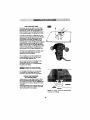
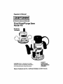
Operator's Manual
P
R
0
F E S
S
I
0
N A L _
Fixed Base/Plunge Base
Router Kit
Model No.
130.26620
CAUTION: Read, understand and follow
all Safety Rules and Operating Instructions
in this manual before using this product.
•
•
•
•
SAFETY
OPERATION
MAINTENANCE
ESPAI_IOL
Sears, Roebuck and Co., Hoffman Estates, IL 60179 U.S.A.
Warranty
............ Page
Safety Instructions..............................................................
Safety Symbols.............. L.....................................................
.
............ Pages
_ .............
Page
Functional Description and Spec f cat ons .......................... i.li i._l............ Pages
Pages
Assembly......
b
Operating Instructions...L......................................................
Maintenance...........................................................................
,.i
ii
Accessodes..............................................................................
2
3 -5
6
7- 8
9- 11
............ Pages 12 - 19
............ Page 20
,
_.ii.............. Page
20
Repair Parts................... _......................................................... .ii,. i ............ Pages 21 - 23
Service Numbers........... .......................................................... ii' _.-f
/............ Back Cover
ONE FULLYEAR WARRANTY ON C
If this Craftsman Toolfails tO
purchase, RETURN IT TO THE
CENTER IN THE UNITED STATES, and Sears will repair it;
This warranty givesyou _iflc
which vary from state tOstate.
legal rights, and you may
Sears, Roebuck and Co. Dept. 817 WA, Hoffman
SAVE THESE
INS_UCTIONS!
READ ALL INSTRUCTIONS!
-2-
Dyear from the date of
; & REPAIR
rights
_Read
and understand all instructions. Failure to follow all instructions
below, may result in electric shock, fire and/or serious personal injury.
SAVE THESE INSTRUCTIONS
listed
Work Area
Keep your work area clean and well lit.
Cluttered benches and dark areas invite
accidents.
reduce the risk of electric shock. Refer to
"Recommended sizes of Extension Cords" In
the Accessory section of this manual.
Do not operate power tools in explosive
atmospheres, such as in the presence of
flammable liquids, gases, or dust. Power
tools create sparks which may ignite the dust
or fumes.
Personal
Safety
Stay alert, watch what you are doing and
use common sense when operating a power
tool. Do not use tool while tired or under the
influence of drugs, alcohol, or medication.
moment of inattention while operating power
tools may result in serious personal injury.
Dress properly. Do not wear loose clothing
or jewelry. Contain long hair. Keep your hair,
clothing, and gloves away from moving
parts. Loose clothes, jewelry, or long hair can
be caught in moving parts. Keep handles dry,
clean and free from oil and grease.
Avoid accidental starting. Be sure switch is
"OFF" before plugging in. Carrying tools with
your finger on the switch or plugging in tools
that have the switch "ON" invites accidents.
Keep by-standers,
children, and visitors
away while operating
a power tool.
Distractions can cause you to lose control.
Electrical
Safet_
Double Insulated tools are sqmpped with a
polarized plug (one blade is wider than the
other.) This plug will fit in a polarized outlet
only one way. If the plug does not fit fully in
the outlet, reverse the plug. If It still does not
fIt, contact a qualified electrician to install a
polarized outlet. Do not cha .n_e the plug in
any way. Double Insulation LOJeliminates the
need for the three wire grounded power
cord and grounded power supply system.
Before plugging In the tool, be certain the
outlet voltage supplied is within the voltage
marked on the nameplate. Do not use "AC
only" rated tools with a DC power supply.
Avoid body contact with grounded surfaces
such as pipes, radiators,
ranges and
refrigerators.
There is an increased risk of
electric shock if your body is grounded. If
operating the power tool in damp locations is
unavoidable, a Ground Fault Circuit Interrupter
must be used to supply the power to your tool,
Electrician's rubber gloves and footwear will
further enhance your personal safety.
Don't expose power tools to rain or wet
conditions. Water entering a power tool will
increase the risk of electric shock,
Do not abuse the cord. Never use the cord
to carry the tools or pull the plug from an
outlet. Keep cord away from heat, oil, sharp
edges or moving parts. Replace damaged
cords Immediately.
Damaged cords increase
the risk of electdc shock.
When operating a power tool outside, use an
outdoor extension cord marked "W-A" or
"W." These cords are rated for outdoor use and
-3-
Remove adjusting keys or wrenches before
turning the tool "ON". A wrench or a key that
is left attached to a rotating part of the tool may
result in personal injury.Do not overreach.
Keep proper footing and balance at all
times. Proper footing and balance enables
better control of the tool in unexpected
situations,
Use safety equipment. Always wear eye
protection. Dust mask, non-skid safety
shoes, hard hat, or hearing protection must be
used for appropdate conditions.
Tool Use and Care
use clamps or other practical way to secure
and support the workpiece
to a stable
platform. Holding the work by hand or against
your body Is unstable and may lead to loss of
control.
Do not force tool. Use the correct tool for
your applicstlon. The correct tool will do the
job better and safer at the rate for which it is
designed.
Do not use tool if switch does not turn it
"ON" or "OFF". Any tool that cannot be
controlled with the switch is dangerous and
must be repaired.
Disconnect the plug/tom the power source
before making any adjustments, changing
accessories,
or storing the tool. Such
preventive safety measures reduce the Hsk of
starting the tool accidentally.
Store Idle tools out of reach of children and
other untrained persons. Tools are dangerous
in the hands of untrained users.
Maintain tools with cere_ Keep cutting tools
sharp and clean. Prope_ maintained tools,
with sharp cutting edges are less likely to bind
and are easier to control. Any alteration or
modification Is a misuse and may result in a
dangerous condition.
Check for misalignment
or binding of
moving parts, breakage of parts, and any
other condition that m_ affect the toolJs
operation,
if damaged,
have the tool
serviced before using. Many accidents are
caused by poorly maintained tools. Develop a
pedodic maintenance schedule for your tool.
that are sold at Sears
that may be
may become hazardous
for your
suitable
when used on ;
Tool service
qualified
maintenance
be performed only by
|ersonnel.
Service or
3rmed by unqualified
dt in a risk of injury. For
may be misplaced or
return springs may be
example:
pinched,
improperly
When
use only identical
replacement _
Follow l_ns
in the
Maintenance_of
this manual.
unauthorized I_rtb or failure to follow
Maintenance Ii_ions
may create a risk of
elsctdc shock €_ lll_ry. Certain cleaning agents
such as gas@il_e, carbon tetrachlcride,
ammonia etc. I_damage
plastic parts.
Hold tool by insulated gripping surfaces
when performing an operation where the
cutting tool may contsct hidden wiring or its
own cord. Contact with a "live' wire will make
exposed metal parts of the tool "live" and
shock the operator, ff _
into existing walls
or other blind areas where electrical wiring may
exist is unavoidable, disconnect all fuses or
circuit breakers feeding this worksite.
Always make sure the work mwface is free
from nails and other toreign objects. Cutting
into a nail can cause the bit and the tool to
Jumpand damage the bit.
Never hold the workpfeGe in one hand and
the tool in the other hand when in use.
Never place hands near or below cutting
surface. Clamping the mstedai and guiding the
tool with both hands is safer.
Never lay workplace
on top of hard
surfaces,
like concrete,
stone, etc...
Protruding cutting bit may cause tool to jump.
Always wear safety goggles end dust mask.
Use only in well ventilated
area. Using
personal safety devices and working in safe
environment reduces risk of injury.
After chang
adjustments,
any uther adj
tightened.
unexpectedly i
loose rotating
thrown,
i
Never start thll
in the mat_
the material di_
cutter.
Always hold
start-up.
cause the tool
The
material Is
the
the tool
cuts will rac
-4-
I
the bits or making any
_sure the conct nut and
_
devices are securely
ladjustment device can
t,_ausing loss of control,
_tponents will be violently
[
when the bit is engaged
bit cutting edge may grab
_|_g loss of control of the
d with two hands during
torque of the motor can
the bit into the
and it relates to
When viewing
top, the bit rotates
of cutting must be
feed direction, refer to
Feeding the tool
causes the cutting edge
and pull the
1of this feed.
Never use dull or damaged bits. Sharp bits
must be handled with care. Damaged bits can
snap during use. Dull bits require more force to
push the tool, possibly causing the bit to break.
Never touch the bit during or immediately
after the use. After use the bit is too hot to be
touched by bare hands.
Never lay the tool down until the motor has
come to a complete standstill. The spinning
bit can grab the surface end pull the tool out of
your control.
Never use bits that have a cutting diameter
greeter than the opening in the base.
8ome dust created by power
sanding, sawing, grinding,
drilling, and other construction
activities
contains chemicals known to cause cancer,
birth defects or other reproductive harm.
Some examples of these chemicals are:
• Lead from lead-based paints,
• Crystalline silica from bricks and cement and
other masonry products, and
• Arsenic and chromium from chemicallytreated lumber.
Your risk from these exposures
varies,
depending on how often you do this type of
work. To reduce your exposure to these
chemicals: work in a well ventilated area, and
work with approved safety equipment, such as
those dust masks that are specially designed to
filter out microscopic particles.
-5-
IMPORTANT:
Some of the following symbols may be used on _=T tool. Please study them
and earn the r mean ng. Prober Interpretat on of these symbolmll_l!i alow you to operate the
tool betterand safer.
Symbol
Name
V
Volts
A
Amperes
Hz
Hertz
W
Watt
kg
Kilograms
min
Minutes
s
Seconds
0
Diameter
no
No load speed
.../rain
0
Time
I wheels, etc.
Revolutions or reciprocation per minute
Off position
1,2,3,...
I, II, III,
Selectorsettings
Infinitelyvariableselectorwith off
..e
Arrow
rection of arrow
Altemating _mant
Directcu_t
I
Altematingor directcurrent
[]
of current
, ,, "_'_=ff,,tedstic
ClassIIconstruction
Design
Con_
'= _ble
Insulated
i tbois.
:i
Groond,.
in,
Earthing terminal
Warning symbol
Alerts u_
Ni-Cad RBRC seal
This symbol designates
that this tool is listed by
G (_)
Underwriters Laboratories.
e
that this tool is listed by
the
Standards
ThisCanadian
symbol designates
Association.
i,iWarningmessages
I_sign_
I1_:11_ttsry
program j
, ,i,p
that this tool is i!_
to
This
symbol
dlNt_nates
Canadian
Stal_,_Uld$by
Underwriters U_l:m_todes.
C_US
-6-
recycling
This symbol
designates
that
this tool
complies
to NOM
Mexican
Standards.
_
Disconnect the
plug fromaccessories.
the power source
before making
any assembly,
adjustments
or changing
Such preventive
safety measures
reduce
the risk of starting the tool accidentally,
Fixed
Base with Motor
Housing
_[_
MOTORHOUSING
ROCKER
ON'OFFSWITCHR AUGNMENTARROW
B_EC_MPL_ER
ROUND
HANDLE
_HIPDEFLECTOR
SUB-BASE
BIT ROTATIONARROW
Voltage rating
Amperage rating
No load speed
Collet capacities
120V "_, 50 - 60Hz
12A
no 8,000 - 25,000/min
1/4", 1/2"
-7-
_r_
Discon_
the plug from the power souroe _
adjustments or ehanglng acoassodes. Such _
the risk of starting the tool aooldentally.
Plunge
Base with Motor
making any membly,
safety measures reduce
Ho_lng
AIRVENTS
SPEEDCONTROL
DIAL
ROCKER
ARROW
DEPTHRODFINE
RODKNOB
- DEPTHROD
BITROTATI_ _ROW
SUB-BASE
Voltage rating
Amperage rating
No load speed
Collet capacities
120V '%, 50 - 60Hz
12A
no 8,000 - 25,000/rain
1/4", 1,,2'
-8-
A wide assortment of muter bits with different
profiles is available separately. Use 1/2" shank
whenever possible, and only use good quality
hits.
ll[tlB_
p__
To
preventremove
personaltheinjury,
always
plug
from power source before removing or
installing bits or accessories.
INSTALLING A ROUTER BIT
Place router upside down or lay muter on its
side with the base resting on the bench.
Another option is to remove the motor from the
base before installingthe bit.
1. Remove the chip shield (or flip up if plunge
bass is attached).
2. Hold the armature shaft in place with the
shaft wrench (Fig. 3)
3. Next, use the collet wrench to loosen the
collet chuck assembly in counter-clockwise
direction (viewed from under the router).
4. Insert the shank of the router bit into the
collet chuck assembly as far as it will go,
then beck the shank out until the cuttem are
approximately 1/8 = to 1/4" away from the
collet nut face.
5. With the router bit inserted and the shaft
wrench holding the armature shaft, use the
collet wrench to firmly tighten the collar
chuck assembly in a clockwise direction
(viewed from under the router). To ensure
proper gripping of the router bit and
minimize run-out, the shank of the router bit
must be inserted at least 5/8".
_FT
COLLET
WRENCH
WRENCH
_When
the template
been removed
from guide
base, has
do
not use router bits greater than 1 5/8"
in diameter as they will not fit through
the sub-base,
To prevent damage to tool,
do not tighten collot without
a bit.
NOTE: The bit shank and chuck should be
clean and free of dust, wood, residue and
grease before assembling.
REMOVING THE ROUTER BIT
1. Use the shaft and collet chuck wrenches as
described earlier, and turn the collet chuck
assembly in a counter-clockwise direction.
2. Once the collet chuck assembly is loosened
continue to turn the coilet chuck assembly
until it pulls the collet fl'se from its taper, and
the muter bit can be removed.
NOTE: The collet chuck is self-extracting; it is
NOT necessary to strike the collet chuck to free
the router bit.
COLLET CHUCK CARE
With the router bit removed, continue to turn
the conet chuck counter-clockwise until it is
free of the shaft. To assure a firm grip,
occasionally blow out the coUet chuck with
compressed air, and clean the taper in the
armature assembly shaft with a tissue or fine
brush.
li[IIB
1
,_
The collet
chuck
is made up of two
component parts as illustrated (Fig. 4); check to
see that the collet is properly seated in the
collet chuck nut and lightly thread the collet
chuck back onto the armature shaft. Replace
worn or damaged collet chucks immediately.
NUT
-9-
LCOLLET
_-,_ |CHUCK
L_t----I
REMOVING
MOTOR
FROM
BASE
Toremove
motorfromfixedbase:
(Fig,
5)
1.Holdrouter
inhorizontal
peslUon, open base
clamp lever, depress coarse adjustment
lever, and pull motor upwards until it stops.
2. Turn motor counter-clockwise, and gently
pull it free of base.
LEVER
To remove motor from plunge base: (Fig. 6)
1. Hold muter in horizontal position, open base
clamp lever, and pull motor upwards until it
stops.
2. Turn motor counter-clockwise, and gently
pull it free of base.
BASE
INSTALLING MOTOR IN BASE8
The motor can be Installed with the switch
positioned on the right or left of the base from
the operator's side (and the cord facing the
opposite side of the muter). Install the motor so
that the switch is in the location you find to be
the most easily accessible _'om the handles.
The switch should be easier to turn "OFF" than
"ON" in case of an emergency.
iCLAMP
LEVER
i
ii
!ii
BASE
To install motor in fixed base."
1, Release the base clamp lever.
2. Une up the arrow on the base with arrow on
the motor. (Fig. 7)
• To position switch on the right side of the
base, line up the base's arrow with motor
houelng's arrow that is below the cord.
• To position switch on the left, line up the
base's arrow with motor heusing's arrow
that is below the switch.
3. While pressing the coarse adjustment lever,
slide motor into base until raslstance in felt.
(The base's guide pin is nOw engaged into
slot on motor.)
4. Continue to press coarse ;adjustment lever,
and turn the motor clockwise until it stops.
5. Push the motor into the base until it reaches
the approximate desired depth.
6. Release the coarse adjustment lever and
slide the motor forward or back as needed
until the coarse adjustment syBtem's "catch"
springs into the coarse adjustment detent
notch.
7. Set final height position as described
"Operating Instructions".
COARSE
ADJUS[MENT
NOTCHES
I
ALIGNMENT
ARROWS
in
BASE
if!
-10-
l,'E_m
INSTALLING MOTOR IN BASES cont.
To install motor in plunge base:
1. Release the base clamp lever+
2. Une up the arrow on the base with arrow on
the motor+ (Fig. 8)
• To position switch on the right side of the
base, line up the base's arrow with arrow
on the motor housing that is below the
cord.
• To position switch on the left, line up the
base's arrow with arrow on the motor
housing that is below the switch.
3. Slide motor into base until resistance in felt.
(The base's guide pin is now engaged into
slot on motor.)
4. Turn the motor clockwise until it stops.
5. Push the motor into the base
as far as it wil! go.
6. Fasten the base clamp lever.
ALIGNMENT
COARSE
ADJUSTMENT
NOTCHES
__J
BASE
Plunge
Base
rmm
CHIP DEFLECTOR
Intended as a safety guard.
The chip deflectors help keep dust and chips
out of your face; it will not stop objects larger
than chips thrown from the bit.
To remove chip deflector shield from fixed base,
press inward on tabs O Fig. 9, until it releases
from base and remove. To instaJIfollow same
directions, and snap back in position, The plunge
base chip deflector shield O Fig. 10, can be
flipped down and back up.
Fixed Base
ld[I ill]
-11-
Plunge
Base
CASTINDICATOR
MMKI
E rGL,_P LEVER
COARSE
LEVER
Fixed Base with Motor
This router is designed for speed, accuracy
and convenience in performing cabinet work,
routing, fluting, beading, cove-cutting, dove
tails, etc. It will enable you to accomplish Inlay
work, decorative edges and many types of
special carving.
DEPTH ADJUSTMENI"
WITH FIXED B/_E
Your router is equipped with a true micrometer
type fine adjustment meshanlsm, which can be
used in any position and provides precise
adjustment of the router bit position for
unmatched accuracy. When the tool is lowered
to the approximate position desired, this device
may be adjusted to preclse!y set the final bit
position.
Your router also features three horizontal
notches on both sides of the motor housing for
coarse adjustments. The notches are spaced
1/2" apart which allows you to quickly lower or
raise the tool depth in three 1/2" Increments,
approximately 12.7 mm, by simply depressing
the coarse adjustment release lever.
TO ADJUST DEPTH
NOTE: All depth adjustments must be made
with the base clamp lever released.
1. Hold the tool In a horizontal posttlonwith the
base clamp lever facing you.
2. Open the base clamp laver to release the
motor.
Hou_
8. COAIP_E ADJ_ rMENT:
To make a larg_ jpth adjustment, depress
coarse adjustma
'elease lever and raise or
lower to desired i
b_The 3 horizontal notches
in the motor ho!_ oare spaced 1/2" apart to
make this adJuelt
_ eselar.
4. FINE DEPTH I
It/6TMENT:
To use the fine _
_ment feature, turn the fine
adjustment kno_ _ Gkwlseto lower the router
bit or counter-ckKt_ _
to raise It.
NOTE: Be sure €
adjustment lever is
engaged in on
coarse adjustment
notches before =
! a fine adjustment.
To allow
the indicator ring is
graduated In
(Note: one full t
fine adjustment knob =
1/16" or a
1.5 mm. The fine
I has a total adjustment
range of 7/8"
Each cast Indicator mark
next to coarse _
equal to 1/8"
To
tool, avoid wedging the
Iower_
Figure 11.
housing as shown in
5. After making depth adjustments, re-clamp
the motor.
The indicator ring may be reset to zero without
moving the fine _atment
knob, to allow the
user to begin tho adjustment
from any
reference point d_.
-12-
TO CLAMP MOTOR
When final coarse and fine adjustments have
been made, fasten the base clamp lever to
secure adjustments. (if additional clamping
force is desired: using a 10 mm wrench, rotate
clamp nut clockwise SLIGHTLY (1/8 turn or
lees), then test clamp. Do not over-tighten.)
DEPTH ADJUSTMENT
WITH PLUNGE BASE
PLUNGING ACTION
The
plunge
feature
simplifies
depth
adjustments and will allow the cutting bit to
easily and accurately enter the workpiece. To
lower, push plunge lock lever to the left, apply
downward pressure until you reach desired
depth, and release pressure on lever to lock
(Fig. 12). The plunge lock lever is spring loaded
and returns automatically
to the locked
position. To raise the router, push plunge lock
lever to the left, release pressure on router and
the router will automatically retract the bit from
the workpiece. It is advisable to retract the bit
whenever it is not engaged In workplace.
DEPTH ROD AND TURRET
The depth rod and the depth stop turret are
used to control cutting depth as follows:
1. With the bit installed, gently lower the motor
until the tip of the router bit just contacts the
level surface the router Is sitting on. This is
the "zero" position, from which further depth
adjustments can be accurately made.
2. To set a desired depth of cut, rotate depth
stop turret until the lowest step is aligned
with the depth rod. Loosen depth indicator
knob and lower the depth rod until it contacts
the lowest step of the turret. Slide the depth
Indicator until the red line Indicates zero on
the depth scale, indicating the point at which
the bit just contacts the work (Fig. 12).
3. To set a desired cutting depth, slide the
depth rod up until the red depth indicator line
attains the desired cutting depth, and secure
the rod in position by firmly tightening the
depth indicator knob.
4.The desired depth of cut may now be
achieved by plunging the router until the
depth rod contacts the selected stop on the
turret.
DEEP CUTS
For deeper cuts, make several progressively
deeper cuts by starting with the highest step on
the depth turret, and after each out, rotate the
depth turret to progressively lower steps as
desired, until the final depth (lowest step or flat)
is reached. Steps progress by 1/8" increments.
To be certain that your depth settings are as
desired, you may want to make test cuts in
scrap matsdal before beginning work.
-13-
_l[flll[q
DEPTH
INDICATOR
KNOB
\
DEPTHRODFINE
ADJUSMENT
KNOB
TURRET
FINE ADJUSTMENT
2. To mlcro-red_
the plunge depth, lower
the fine adj_
stop by turning it
clockwise by the daslred amount.
The plunge base is equipped with a fine
adjustment system that allows you to micro
adjust the plunge depth of the router bit for
supedor routing accuracy.
Each complete revolution of the fine adjustment
stop adjusts the plunging depth by 1/32", and
each of the four indicator marks on the knob
represents 1/128". One of the four tick marks is
larger than the other to indioate a complete
revolution. A reference indicator line is built in
to the depth rod.
To use the fine adjustment knob, once the
depth rod and turret have been set, check the
final depth setting and fine-adjust as follows:
1. To micro-Increase the plunge depth, raise
the fine adjustment stop by turning it
counter-clockwise by the dashed amount.
Notes:
• When micro-_!ng
the plunge depth, it is
more convan_
to move the fine adjustment
stop up than ;_
Before seffing the depth
rod and turre_ m=ke sure the fine adjustment
stop has been: turned several revolutions
down from Its 1_ position so that it can be
adjusted u_
• The fine adjull_rwnt stop cannot be used to
reduce the _
depth when the depth rod
is already toucthing the depth stop turret. The
router must be raised before such an
adjustment can be made.
-14-
ELECTRONIC VARIABLE SPEED CONTROL
ROCKER uON/OFF" SWITCH
Your tool can be turned "ON" or "OFF" by the
rocker switch located on the motor housing.
One side of the switch is marked "1" for "ON",
and the other side of switch is marked "O" for
"OFF". Also the edge of switch displays red
when switch is in the "ON" position.
TO TURN THE TOOL uON": Push the side of
the switch marked "r'.
TO TURN THE TOOL "OFF": Push the side of
the switch marked "O".
Always hold the router off the work when
turning the switch on or off. Contact the
work with the router after the router has
reached full speed, and remove it from the
work before turning the switch off. Operating in
this manner will prolong switch and motor life
and will greatly increase the quality of your work.
The electronic speed control feature allows
motor speed to be matched to cutter size and
material hardness for improved finish, extended
bit life, and higher performance.
Speed
changes are achieved by rotating Control Dial
RIGHT to increase speed, LEFT to decrease as
indicated on housing. Speed may be changed
while tool is on. The reference numbers on
the dial facilitate re-setting control to desired
speed.
The speed chart indicates the relationship
between
settings and application,
exact
settings are determined by operator experience
and preference. The bit manufacturer may also
have a speed recommendation.
DIAL
SETTING
SOFT START FEATURE
Electronic feedback control minimizes torque
twist customary in larger routars by limiting the
speed at which motor starts.
RPM
APPLICATION
1
8,000
"1 Nonferrous metals,
2
3
13,500
16,500
j_ larger diameter bits,
and cutters
4
5
6
20,000
21,500
25,000
"t Softwoods, plastics,
smaller
_- counter tops,
j diameter bits, and
cutters
ELECTRONIC FEEDBACK CIRCUITRY
The router's Electronic Feedback Circuitry
monitors and adjusts power to maintain the
desired RPM for consistent performance and
control.
-15-
FEEDING
THEROUTER
ASseenfromthetopoftherooter,
thebit
turnsclockwise
andthe cutting edges face
I_m ilm!
accordingly.Therefore,the most efficientcut
is made by feeding the routerso that the bit
turns into the work, not away. Figure 14
showsproperfeed for variouscuts. How fast
you feed depends on the hardness of the
material and the size of the cut. For some
materials,it is best to make severalcuts of
increasingdepth.
If the router is hardto control,heats up, runs
very slowly or leaves an imperfect cut,
considerthesecauses:
1. Wrongdirectionof feed -- hardto control.
2. Feedingtoo fast -- overloedsmotor.
3. Dullbit -- overloadsmotor.
4. CUtis too la_e for one pass -- overloads
motor.
5. Feedingtoo slow -- leaves friction bums
on work.
Feed smoothly and steadily (do not rome).
You will soon learn how the router sounds
and feels when it is workingbest.
$
i
DIRECTION
OF
ROUTER
FErn
OFFEED
When routing _ng
related work in wood
and plastics, th_ best finishes will result if
the depth of c_ _
feed rate are regulated
to keep the _
Operating at high speed.
Feed the rou_e_t
a moderate rate. Soft
materials require _!faster feed rate than hard
materials.
The router may stall if improperly used or
overloaded. _
the feed rate to prevent
possible damag_to the tool. Always be sure
the oollet chuc_ !_1tightened securely before
use. Always um!_uter bits with the shortest
cutting length _oessary
to produce the
desired cut. _
_i minimize router bit runout and chatter.
GUIDING THE ROUTER
The router can be guided through the work
in any of several ways. The method you use
depends, of course, on the demands of the
particular job and on convanience.
For routing operations such as grooving or
dadoing, it is often necessary to guide the
tool in a line parallel to a straight edge. One
method of obtaining a straight cut is to
securely clamp a board or other straightedge
to the work surface, and guide the edge of
the router sub-base along this path (Fig. 15).
FEED
DIRECTION
BOARD
GUIDE
SECURELY
CLAMP
BOARD
GUIDE
-16-
CENTERING
THE
SUB-BASE
AND
TEMPLATE GUIDE BUSHINGS
Your router's sub-base is precisely centered
at the factory. This positions the bit at the
center of the sub-base and the template guide
bushings (sold separately). This allows you to
closely follow jigs, such as straight guides,
templates and dovetatl fixtures without having
the bit "walking off" from the intended cut line
for any reason, including the orientation of the
router's handles.
In the event that the sub-base or template
guide bushings need to be adjusted, follow
these steps:
1. Position the sub-base so the screw holes
are over the matching set of threaded
holes in the base.
2. Insert the screws through the sub-base and
tighten them until they are snug, but still
allow the sub-base to move.
3. If a template guide bushing (sold separately)
is being used, (Fig. 16) attach it
as described In Figs 17 and 18.
4. Adjust the sub-base until the sub-base or
template guk:lebushing is centered around
the bit as shown In Fig 19.
Edlfllil_
ATTACHING
TEMPLATE
GUIDE
BUSHING
TO FIXED
BASE
SUB-BASE
O 3 Screw Holes
) Template Guide Bushing (soldseparately)
) Router Bit (soldseparately)
ATTACHING TEMPLATE GUIDE
BUSHING TO PLUNGE BASE
TEMPLATE GUIDE BUSHINGS
Your router's sub-bases are ready to accept
the Craftsman Router Template Guide Bushing
Set (9-25082), sold separately.
Template guides are used with a number of
special aoseesodes, such as dovetail fixtures
and hinge templates. In addition, special
templates are easily prepared for cutting
repeated patterns, special designs, inlays,
and other applications. A template pattern
can be
made of plywood, hardboard, metal or even
plastic, and the design can be cut with e router,
jigsaw, or other suitable cutting tool.
Remember that the pattern will have to be
made to compensate for the distance between
the router bit and the template guide
(the "offset"), as the final workplace will differ in
size from the template pattern by that amount,
due to the bit position.
-17-
TO A'n'ACH TEMPLATE GUIDE
BUSHINGS TO ROUTER
1. DISCONNECT ROUTER FROM POWER
SUPPLY WHILE ASSEMBLING PARTS
2. Attach the guide bushing directly to the
inside of the sub-base as shown In Figs. 17,
18,19. DO NOT remove the sub-base from
your muter to attach the guide bushing.
3. Secure the guide bushing to the sub-base
with the 3 screws supplied (#10-32 x 5/8 flat
head). Shown in Fig. 16. BE SURE the collar
section of your guide bushing is turned
facing away from the router motor. (See Figs.
17, 18, 19)
4. Open the base clamp lever to release and
lower the router motor in router base untilthe
collet nut is approximately 1/8-Inch clear of
guide bushing.
5. After making adjustment, re-clamp the motor.
6. Insert router bit through guide bushing and
into collar at least 1/2-inch, Fig. 19.
7. Tighten collst nut securely.
8. Visually center the cutter with the inside
diameter of the guide bushing. NOTE:
Adjustments can be made by loosening
the screws holding the sub-base to the
router,
9. Tighten all screws securely. WARNING:
FAILURE TO CENTER CUTTER WITH
BUSHINGS OR FAILURE TO FIRMLY
TIGHTEN SCREWS AFTER CENTERING
COULD CAUSE THE CUTTER TO COME
IN CONTACT WITH THE GUIDE
BUSHING, RESULTING IN POSSIBLE
SERIOUS INJURY.
WARNING; _LWAYS WEAR SAFETY
GLASSE_ _i EYE SHIELDS WHEN
OPERATIN_ YOUR POWER TOOL.
O_ERATION
1. Place your router, with guide bushing
attached, a_!_St template. The template
will serve as it guide and restrict the
movement of your router within the
desired area being cut.
2. Grasp your mUter and hold It firmly with
both hands.
3. Turn router on and let the motor build to
its full speed_
4. Gradually feed the cutter into workpiece.
WARNING: KEEP A FIRM GRIP ON
ROUTER WITH BOTH HANDS AT ALL
TIMES. FAILLE
TO DO SO COULD
RESULT IN_S$
OF CONTROL
LEADING TO! POSSIBLE SERIOUS
INJURY.
5. Upon completion of out, turn motor off
and let it come to a complete stop before
removing router from work surface.
The following _€ommended
templates
are available at your nearest Sears
Full-Line Retail Store or at
www.craftsrnan;.com on the internet.
Butt Hinge Ts_!ates
Dovetail Templtte
Box Joint Template
Letter and Si_ Making Template Set
Replacement _ettar Template Set
See the table _
for proper selection
of bushings, cutters and templates
BUSHING, CUTTERAND TEMPLATETABLE
I i
GUTTERDIA
TYPE.
5/16-1n.
1/4 INCH
DOVETAIL
BIT
DOVETAIL
5/8-in.
1/2 INCH
STRAIGHT
BIT
BUTTHINGE
7116-in.
1/2 INCH
DOVETAIL BIT
DOVETAIL
5/1 6-1n,
114INCH
SmA,G
oct BoXJOl
5t8-1n,
1/2 INCH
STRAIGHT
BIT
BUSHING
PILOT 0.0.
-18-
TEMPLATE
BOXJOINT
USE IN ROUTER TABLE
Your router can also be used in a router table.
The fixed base is dasigned to allow easy depth
adjustment in a table. The plunge base is not
recommended for use in a router table because
it may cause damage to the plunge router base.
To install the fixed base in a table (sea Fig. 20),
simply remove the sub-base and attach the base
using three #10-32 fiat head machine screws
(not included). The length will depend on the
thickness of your router table or router table
mounting plate. Follow the ddlllng and ir_tallatlon
instructions that were Included with the router
table. In order to use the over table adjustment
feature on your router, you will also need to ddll
a hole in the router table or mounting plate to
allow access to the fine depth adjustment rod.
The depth can be adjusted over a 7/8-in. range
from above the table using the over-table
adjustment wrench (included).
When installinga router bit be sure that the
coarse adjustment level is near the lowest
point of the depth Indicator ring.
Also be sure the muter bit is installed at the
proper height for the cut to be made,
(the height of the first cut, ff multiple passes
are going to be made).
ALWAYS re-clamp the motor in the base
BEFORE turning on the motor and routing.
For complete instructions on the operation
of a muter in a router table, refer to the
instructions that come with the router table.
FEEDING THE WORKPIECE
ON A ROUTER TABLE
Always use your router table's fence or starter
pin and the appropriate guard end follow the
router table's instruction manual. ALWAYS feed
the workpiece from right to left across the front
of the bit.
Whenever possible, when usingthe fence, use
a push stick to push the workpleoe, especially
when working with narrow plecas.
WORKPIEGE
BEARIN6
TOPVIEW
NOTE: For clarity, guard and featherboard
removed from drawing.
-19-
SERVICE
recommendthat _ takethe toolto a Sears
ServiceCenter _ havethe brushesexamined
everytwo to sixes
dependingon the amount
of toolusage._m
replaoomentbrushesthat
arespecially_for
use withyour
CRAFTSMAN_onal
Router.
personnel may result in ml_slaclng of internal
wires and components, which could cause a
serious hazard,
1. ToolserviceMUST BE pedoneadonlyby Sears
Service Center. Serviceor maintenance
performedby unqualifiedpersonnelcouldresultin
a dskof injury,
BEARINGS
Afterabout300 tO400 hoursof operation,or at
everysecond_nange,
the bearingsshould
be replacedby _
ServiceCenter. Bearings
whichbecome_
(dueto heavyloador very
abrasivematedal_g}
shouldhe replaced
immediatelyto avfddoverheatingor motorfailure,
; CLEANING
IMPORTANTNOTE= Allservicethat requires
openingthetool shouldonlybe performedat a
Sears ServiceCenter.
2. Whenservicinga tool, ALWAYSuse onlyidentical
repiscementparts.Followinstructior_inthe
MaintenanceSectionofthismanual.Useof
unauthorizedpartsor failureto follow
MaintenanceInstructionsmay createa riskof
electricshockor injury.
TOOL LUBRICAllON
Your CRAFTSMANProfessionalRouterhas been
properlylubricatedandis readyto use. It is
recommendedthattoolswith geam be mgreaasd
with a specialgear lubricantwhene_r brushesere
changed.
CARBON BRUSHES
Thebrushesend commutatorinyour CRAFTSMAN
ProfessionalRouterhave beanenglnserodto
providemany hoursof dependableservice,
To maintainthe peak efficiencyof the motor,we
Thefollowing recommendedao0eseodeaere
currentlyavailableat yourlocalSears Store.
EXTENSIONCORDS
If an extensl_
cord Is
necessary,
a_ord
with
adequate size conductors that it Papable of
canrylng the current necessary for your tool
must be used. This will prevent excessive
voltage drop, loss of power or overheating.
Grounded tools must use 3-wire extension
cords that have 3-prong plugs and receptacles.
any malntermnO(k_Tha
toolmay be cleanedvery
effectivelywithc_
air. ALWAYS wear
safety goggles_
oleanlngtools with
compreaeadair.Vltntilation openingsand switch
leversmustbe Imptdean andfree of foreignmatter.
DONOT attemptt= clean by insertingpointed
objectsthrough:theopenings,
p_l'_
GMteln cleaning agents and
s'='m_mii=_m l_llVsets cause damage to the
plastic parts. _
Includegasoline,carbon
te_achlodde, _atad
cleaningsolvents,
ammoniaand _ld
detergentsthat contain
ammonia.
RECOMMENENIDEII_
_116_S (OF _
FPa l_-vour _
Tolrl
k'_pem
RaUng
3 6
6-8
8-10
10-12
12-16
cunnr=ml_
WIll SIZEShi mme
Cord _
II &._.
.....
CON Lnlell II RIM
25
18
18
18
16
14
50
le
16
16
16
12
111
16
14
14
14
CORDS
CordI._oUt
11ill
14
12
12
12
16
.75
,75
,75
t.0
SO
,75
10
10
2,5
In Melen
60
!.5
2,5
2.5
4.0
t20
25
4.0
4.0
SEARSOFl=lm8 A LARGESELECTiON
OF ACCE_MIORm8FOR YOUR ROUTER
NOTE: The smaller the gauge number, the
greater capacity of the cord. 16 gauge wire
has more capacity than 18 gauge wire.
• Individual
routerbitsanda • Template
GuideBushings
varietyofrouterbitsets
• Hin0eMortising
Tanll_e Kit • 12-inDovetail
Template
Kit
• 16-iflchDovetail/Bo0(
• RouterTables
JointSystem
Im m
recommended _
-20-
be dangerous.
ROUTER
KIT-
MODEL
The Model Number will be found on the
Nameplate.
Always mention the Model Number in all
correspondence regarding your tool.
SEE BACK PAGE FOR PARTS ORDERING
INSTRUCTIONS.
NUMBER
130.26620
PARTS UST
Motor
Pos. Part Number
1 2610922584
2 3604220569
3 3604011620
4 2610913918
7 2601035001
13 3600905513
14 3600905512
21 2610991373
22 1604477005
29 2610993582
30 2610906283
30 2610906284
31 2610923210
32 2610991375
33 1900210115
34 2610923212
35 2610923175
61 2910611006
62 2616991306
74 2910641120
75 2610910566
77 2910141166
653 2610992417
654 2610991388
803 3601352502
804 360t352501
805 3604460560
806 3600703512
810 3604321514
816 3604336506
817 3604652501
Description
Qty
Motor Housing
1
Field
1
Armature
1
Switch
1
Cord Clamp
1
Ball Bearing
1
Ball Bearing
1
Baffle
1
Terminal
2
Nut
1
Collet Assembly 1/4"
1
CoUetAssembly 1/2"
1
Rear Housing
1
Bearing Sleeve
1
O-Ring
1
Cover
1
Speed Control
1
Screw
4
Screw
2
Screw
2
Screw
4
Screw
2
Wrench 24mm
1
Wrench 16mm
1
Terminal
1
Terminal
1
Cord
1
Strain Relief
1
Brush Set
1
Brush & Holder Set
1
Brush Spdng Set
1
ROUTER KIT - MODEL NUMBER
The Model Number will be found on the
Nameplate.
Always mention the Model Number In all
correspondence regarding your tool.
SEE BACK PAGE FOR PARTS ORDERING
INSTRUCTIONS.
PARTS LIST
Fixed Base
Pos. Part Number
39 2610919706
40 2610922557
41
1613300006
42 2610915060
44 2610922527
45
2610991385
46
2610991371
48
2610993576
49
2610993577
50
2610922560
55
2610991389
56
2610991372
63
2910011219
66
2918660004
70
2610996054
71
2610994492
73
2610917210
75
2916079032
76
2916011013
655
2610923193
130.26620
Description
Qty
Handle
2
Base
1
_
1
Clamp Lever Assembly
1
Adjusting ROd
1
_Lever
1
Spdng
1
Knob
1
Indicator Ring
1
_JbBase
1
Cttlp Shield
1
_
1
Screw
2
Washer
1
Retaining Ring
1
Pin
1
Screw
3
LockWasher
2
Washer
2
T-Handle Hex Wrench 1/8" 1
63
7O
655 m
-22-
Replacement
ROUTER
KIT - MODEL
The ModeJ Number will be found on the
Nameplate.
Always mention the Model Number in all
correspondence regarding your tool.
SEE BACK PAGE FOR PARTS ORDERING
INSTRUCTIONS.
PARTS LIST
Plunge Base
Pos. Part Number
110
2610912594
111
2610990022
112
2610914852
116
2916079032
117
2610994492
118 2610996143
119
2610913441
120 2610919932
121 2610920770
122 2610914639
123 2610912598
124 3605510548
125 2610917210
Dascdptlon
Qty
DustCover
1
Screw
1
Clip Plug
1
LockWasher
2
Pin
1
Screw
2
Screw
4
Right Handle
1
Left Handle
1
Support DIsc
2
Compression Spdng 2
Bellow
2
Screw
3
Parts
NUMBER
Pos.
127
130
131
144
145
146
147
148
155
156
157
158
159
160
161
170
171
172
173
183
184
186
801
826
Part Number
2610922561
2916650003
1900210111
3603450504
3604651503
3602000510
2910641122
2916680005
2610912599
2610922093
2610997094
2610912600
2610917057
2610912601
2610068154
3600232503
2600590006
3603415556
3916060500
2918660004
1613300006
2610915060
2610923153
2610997115
119
till
11o
121
-23-
130.26620
Description
Qty
Sub Base
1
Retaining Ring
1
O-Ring
1
Lock Bolt
1
Spring
1
Lever
1
Screw
1
Lock Washer
1
Chip Deflector
1
Depth Label
1
Pointer
1
Rod
1
Wing Screw
1
Adjustment Knob
1
O-Ring
1
DepthStop
1
Cap/Spring
1
Screw
1
Washer
1
Washer
1
Nut
1
Clamp Lever Assembly 1
Motor Carder Aesembly 1
Base Assembly
1
i i i iii
iiii!!i!!ii
!ii
i:ili
iii¸¸¸¸
,i ..........................
,,
Your Home
;;
For repair in your home of all major brand appliances,
lawn and garden equipment, or heating and cooling systems,
no matter who made it, no matter who sold it!
For the replacement parts, accessories and
owner's manuals that you need to do-it-yourself,
For Sears professional installation of home appliances
and items like garage door openers and water heaters.
1-800-4-MY-HOME
_
(1-800-469-4663)
www.seara.com
Anytime,
clay or night
(U.S.A. and Canada)
www.sears.ca
Our Home
For repair of carry-in products like vacuums, lawn equipment,
and electronics, call or go on-line for the nearest
Sears Parts and Repair Center.
1-800-488-1222
Anytime,
day or night (U.S.A.
only)
www.sears.com
To purchase a protection agreement(U.S.A.) or maintenance
agreement (Canada) on a productserviced by Sears:
1-800-827-6655 (u.sJ_)
1-800-361-6665 (Canada)
Parepedir serviciode reparacibn
a domicilio,y pare ordenar piezas:
........
1"888"SU'HOGARsM
Au Canada pour serviceen frsJ'K_US:
1.800.11=.FOYERMC
_:i;!:i!i;i:i;i:i:
(1-800.533-6937)
www.sears.ca
(1-888-784-6427)
....
_i;!iiiiiiiiiiiiiiiiiiii
_
© Sears, Roebuck and Co.
® Registered
® Marca
Marque
Trademark
Registrada
/ TM Trademark
/ "n_Marce
de commerce
/ sM Service
de F, brica
t _o Marque
/ s_ Marca
ddposde
Mark
of Sears,
de Servicio
de Sears,
Roebuck
Roebuck
de Sears.
end Co,
and Co.
Roebuck
and Co.