1
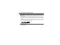
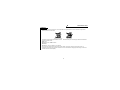
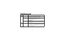
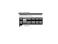
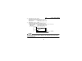
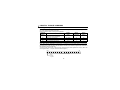
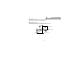
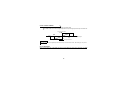
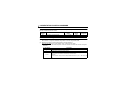
VECTOR INVERTER
VECTOR INVERTER
-INSTRUCTION MANUAL-
16-BIT DIGITAL INPUT
FR-V5AH
HEAD OFFICE:MITSUBISHI DENKI BLDG MARUNOUCHI TOKYO 100-8310
IB(NA)-0600110E-A (0203) MEE
Printed in Japan
Specifications subject to change without notice.
Thank you for choosing the Mitsubishi vector inverter option unit.
This instruction manual gives handling information and precautions for use of this equipment. Incorrect handling
might cause an unexpected fault. Before using the equipment, please read this manual carefully to use the equipment
to its optimum.
Please forward this manual to the end user.
This section is specifically about safety matters
Do not attempt to install, operate, maintain or inspect this product until you have read through this instruction manual and appended documents carefully and can use the equipment correctly. Do not use this product until you have
a full knowledge of the equipment, safety information and instructions.
In this instruction manual, the safety instruction levels are classified into "WARNING" and "CAUTION".
WARNING
Assumes that incorrect handling may cause hazardous conditions, resulting in
death or severe injury.
CAUTION
Assumes that incorrect handling may cause hazardous conditions, resulting in
medium or slight injury, or may cause physical damage only.
Note that the CAUTION level may lead to a serious consequence according to conditions. Please follow the instructions of both levels because they are important to personnel safety.
SAFETY INSTRUCTIONS
1. Electric Shock Prevention
WARNING
! While power is on or when the inverter is running, do not open the front cover. You may get an electric shock.
! Do not run the inverter with the front cover removed. Otherwise, you may access the exposed high-voltage terminals and charging part and get an electric shock.
power is off, do not remove the front cover except for wiring or periodic inspection. You may access the
charged inverter circuits and get an electric shock.
! Before starting wiring or inspection, switch power off, wait for more than 10 minutes, and check for no residual
voltage with a tester or the like.
! If
A-1
WARNING
! Any person who is involved in the wiring or inspection of this equipment should be fully competent to do the work.
! Always install the option unit before wiring. Otherwise, you may get an electric shock or be injured.
! Handle this option unit with dry hands to prevent an electric shock.
! Do not subject the cables to scratches, excessive stress, heavy loads or pinching. Otherwise, you may get an electric shock.
2. Injury Prevention
CAUTION
! Apply only the voltage specified in the instruction manual to each terminal to prevent burst, damage, etc.
! Ensure that the cables are connected to the correct terminals. Otherwise, burst, damage, etc. may occur.
! Always make sure that polarity is correct to prevent burst, damage, etc.
! While power is on or for some time after power-off, do not touch the inverter as it is hot and you may get burnt.
3. Additional instructions
Also note the following points to prevent an accidental failure, injury, electric shock, etc.:
(1) Transportation and mounting
CAUTION
! Do not install or operate the option unit if it is damaged or has parts missing.
! Do not stand or rest heavy objects on the product.
! Check that the mounting orientation is correct.
! Prevent screws, metal fragments or other conductive bodies or oil or other flammable substance from entering the inverter.
(2) Test operation and adjustment
CAUTION
! Before
starting operation, confirm and adjust the parameters. A failure to do so may cause some machines to
make unexpected motions.
A-2
(3) Usage
WARNING
! Do not modify the equipment.
CAUTION
! When parameter clear or all parameter clear is performed, each parameter returns to the factory setting. Re-set
the required parameters before starting operation.
! For prevention of damage due to static electricity, touch nearby metal before touching this product to eliminate
static electricity from your body.
(4) Maintenance, inspection and parts replacement
CAUTION
! Do not test the equipment with a megger (measure insulation resistance).
(5) Disposal
CAUTION
! Treat as industrial waste.
(6) General instruction
All illustrations given in this manual may have been drawn with covers or safety guards removed to provide indepth description. Before starting operation of the product, always return the covers and guards into original positions as specified and operate the equipment in accordance with the manual.
A-3
CONTENTS
1.PRE-OPERATION INSTRUCTIONS
1.1
1.2
1.3
Unpacking and Product Confirmation ..................................................................................................1
Packing Confirmation...........................................................................................................................1
Structure ..............................................................................................................................................2
2.INSTALLATION
2.1
2.2
2.3
8
Wiring Examples ..................................................................................................................................8
Terminals ...........................................................................................................................................10
Code Input .........................................................................................................................................11
4.DIGITAL SPEED COMMAND
4.1
4.2
4.3
3
Pre-Installation Instructions..................................................................................................................3
Installation Procedure ..........................................................................................................................3
Wiring...................................................................................................................................................5
3.16-BIT DIGITAL INPUT
3.1
3.2
3.3
1
12
Digital Speed Command Parameter ..................................................................................................12
Parameter Setting ..............................................................................................................................13
Instructions.........................................................................................................................................17
5.DIGITAL TORQUE COMMAND
5.1
5.2
5.3
Digital Torque Command Parameters ...............................................................................................18
Parameter Setting ..............................................................................................................................18
Instructions.........................................................................................................................................20
6.ORIENTATION POSITION COMMAND
6.1
6.2
21
Orientation Position Command Parameter ........................................................................................21
Parameter Setting ..............................................................................................................................21
7.SPECIFICATIONS
7.1
18
23
Specifications.....................................................................................................................................23
1.PRE-OPERATION INSTRUCTIONS
1.1 Unpacking and Product Confirmation
Take the option unit out of the package, check the unit name, and confirm that the product is as you
ordered and intact.
This product is an option unit designed for exclusive use in the Mitsubishi FR-V500 series vector inverter.
" SERIAL number check
This product may be used with the FR-V500 series manufactured in and after March 2002. Any of the
models may be used with this unit if its SERIAL number indicated on the rating plate and package has
"#23######" or later version. For details of the SERIAL number, please contact your sales representative.
SERIAL is made up of 1 version symbol, 1 alphabet letter or numeric character indicating month, and 7
numeric characters indicating the year and control number as shown below. (Only the first three digits
of the control number are printed on the package.)
2
3
######
#
Symbol Year Month Control number
SERIAL number
1.2 Packing Confirmation
Make sure that the package includes the following
" Instruction manual.........................................................................1
" Mounting screws M3 × 10 .............................................................2
1
PRE-OPERATION INSTRUCTIONS
1.3 Structure
Front view
Mounting holes
Rear view
Mounting
hole
Mounting
hole
DY
X15
X14
X13
X12
X9
X11
X8
X10
X7
X6
X5
X4
X3
X2
X1
X0
SD
SD
SD
Terminal
Terminal
symbol
FR-V5AH
Option fixing holes
2
Connector
2.INSTALLATION
2.1 Pre-Installation Instructions
Make sure that the input power of the inverter is off.
CAUTION
With input power on, do not install or remove the option unit. Otherwise, the inverter and
option unit may be damaged.
2.2 Installation Procedure
(1) Securely insert the connector of the option unit far into the connector of the inverter. At this time, fit the
option fixing holes snugly.For the position of slot, refer to the next page.
Also be sure to fit the unit into the option fixing hook.
(2) Securely fix the option unit to the inverter on both sides with the accessory mounting screws. If the
screw holes do not match, the connector may not have been plugged snugly. Check for loose plugging.
3
INSTALLATION
Option unit
Inverter
(without cover)
Accessory screw
(2 pcs.)
Slot 1
Option side
connector
Inverter side connector
Slot 2
Option fixing hook
Slot 3
The slots 1, 2, and 3 are provided
with an option fixing hook.
CAUTION
1. Only one type of option per inverter may be used. When two or more options are mounted, priority is in order of slots 1, 2 and 3, the options having lower priority are inoperative.
2. When the inverter cannot recognize that the option is
Mounting Position Error Display
mounted, it displays the option error. The errors shown
Slot 1
E.OP1
differ according to the mounting slots 1, 2, 3.
Slot 2
Slot 3
4
E.OP2
E.OP3
INSTALLATION
2.3 Wiring
Wiring method
1) For wiring the control circuit, use cables after stripping their sheaths.
Strip the sheaths to the following dimensions. If the sheath is stripped too much, its cable may be shorted
with the adjoining cable. If the sheath is stripped too little, the cable may come off.
Cable stripping size Wire the stripped cable after twisting
5
it to prevent it from becoming loose.
In addition, do not solder it.*
*Information on bar terminals
Introduced products (as of Mar., 2002): Phoenix Contact Co.,Ltd.
Terminal Screw Size
Bar Terminal Model
(With Insulation Sleeve)
Bar Terminal Model
(Without Insulation Sleeve)
Wire Size (mm2)
M2
Al 0.5-6WH
A 0.5-6
0.3 to 0.5
• Bar terminal crimping terminal: CRIMPFOX ZA3 (Phoenix Contact Co., Ltd.)
CAUTION
When using the bar terminal (without insulation sleeve), use care so that the twisted wires do not
come out.
5
INSTALLATION
2) Loosen the terminal screw and insert the cable into the terminal.
Screw size: M2
Tightening torque: 0.22N·m to 0.25N·m
CAUTION
Undertightening can cause cable disconnection or malfunction. Overtightening can cause a short
circuit or malfunction due to damage to the screw or unit.
Cable size: 0.3mm2 to 0.75mm2
Screwdriver: Small flat-blade screwdriver
(Tip thickness: 0.4mm (0.02inches)/tip width: 2.5mm (0.10inches))
6
INSTALLATION
Route the wires so that they do not take up a lot of space in the control circuit terminal block of the option unit.
During wiring, do not leave wire off-cuts in the inverter. They may cause a fault, failure or malfunction.
Use the space on the left side of the control circuit terminal unit to route the wires.
Cable routing
REMARKS
The wires with large gaze may not be connected to the terminal block. When connected in parallel, all wires may not
fit in the wiring space due to the increased number of wires. In such cases, perform wiring by using a junction terminal block.
CAUTION
When installing the inverter front cover, the cables to the inverter's control circuit terminals
and option terminals should be routed properly in the wiring space to prevent them from
being caught between the inverter and its cover.
7
3.16-BIT DIGITAL INPUT
3.1 Wiring Examples
(1)Relay contact signal input
8
4
2
1
8
4
2
1
8
4
2
1
8
4
2
1
X15
X14
X13
X12
X11
X10
X9
X8
X7
X6
X5
X4
X3
X2
X1
X0
DY
SD
(2)Open collector signal input
FR-V5AH
Y41 type transistor
utput module *2
Read command
FR-V5AH
1
2
3
4
5
6
7
8
9
10
11
12
13
14
15
16
17
18
19
35
36
X15
X14
X13
X12
X11
X10
X9
X8
X7
X6
X5
X4
X3
X2
X1
X0
DY
PC*1
Inverter
(For sink logic)
*1 Use the terminal PC on the inverter.
*2 AY41 type unit requires 24VDC power.
A wiring example of Mitsubishi PLC output module (AY41 type). For details of the output module, refer
to the instruction manual of the output module.
8
16-BIT DIGITAL INPUT
REMARKS
1. As the input signals are at low level, use two parallel micro signal contacts or a twin contact for relay contact
inputs to prevent a contact fault.
Micro signal contancts
Twin contancts
2. A transistor of the following specifications should be selected for the open collector signal: Electrical characteristics of the transistor used
• Ic ≥ 10mA
•Leakage current: 100µ
µA maximum
•VCE ≥ 30V
• If Ic ≥ 10mA, VCE (sat) voltage is 3V maximum
3. The control logic is the same as that of the inverter (factory-set to sink). When the logic of the inverter is
changed to source, the option logic also switches to source. For details on changing the control logic, refer to the
inverter instruction manual (basic).
9
16-BIT DIGITAL INPUT
3.2 Terminals
Terminal
Location
Terminal Symbol
X0 to X15
Option unit
DY
SD
Inverter
PC
Description
Digital signal input terminals (speed setting signal terminals)
Used to input a 4-digit BCD (9999 maximum) or 16-bit binary (FFFFH maximum) relay contact or open collector signal. (refer to page 11)
Data read timing input signal
Used when a digital signal read timing signal is necessary.
Data is only read while the DY signal is on.
By switching the DY signal off, the X0 to X15 data before signal-off is retained.
(Refer to page 13.)
Common terminal (sink)
Common terminal for digital and data read timing signals.
This terminal is the SD terminal of the inverter. Common terminal for the SD
terminal of the inverter.
External transistor common terminal (source)
When connecting the transistor output (open collector output) of a programmable controller (PC), etc., connect the external power common (+) to this terminal to prevent a fault occurring due to leakage current. When you have selected
the source logic, this terminal is used as a common terminal. This terminal is
the PC terminal of the inverter.
10
16-BIT DIGITAL INPUT
3.3 Code Input
The following lists examples of terminal input state and input value for BCD code and binary code input.
In the case where BCD code is "6325"
BCD Code Input
Terminal input
Digit Terminal
Input value
state
1
10
100
1000
X0
X1
X2
X3
X4
X5
X6
X7
X8
X9
X10
X11
X12
X13
X14
X15
ON
OFF
ON
OFF
OFF
ON
OFF
OFF
ON
ON
OFF
OFF
OFF
ON
ON
OFF
5
2
3
6
In the case where Binary code is "AB65H"
Binary code input
Terminal input Input value Input value
Terminal
(hexadecimal)
(decimal)
state
X0
X1
X2
X3
X4
X5
X6
X7
X8
X9
X10
X11
X12
X13
X14
X15
ON
OFF
ON
OFF
OFF
ON
ON
OFF
ON
ON
OFF
ON
OFF
ON
OFF
ON
5
6
43877
B
A
CAUTION
Range of each digit is from 0 to 9. If the value of a digit is greater than 9, the value is invalid and
the previous value is kept.
11
4.DIGITAL SPEED COMMAND
4.1 Digital Speed Command Parameter
Use the following parameters to give a speed command using the FR-V5AH. The following parameters can
be set when the FR-V5AH is fitted.
This option unit does not function if the parameter values are factory setting values. When Pr.304 ≠ "9999",
a speed command by the 16-bit digital input is made valid.
Set the following parameter values according to the application:
Parameter
Number
300
301
302
303
Setting
Range
Setting
Increments
Bias
0 to 3600r/min
0.1r/min
0r/min
Gain
0 to 3600r/min, 9999
1r/min
1500r/min
Bias
0 to 3600r/min
0.1r/min
0r/min
Gain
0 to 3600r/min, 9999
1r/min
1500r/min
0, 1, 2, 3, 9999
1
9999
0, 1
1
0
0, 1, 2
1
1
Function name
BCD code input
Binary input
304
Selection of digital input type and analog
compensation input enable/disable
305
Data read timing signal on-off selection
329
Digital input unit selection
Factory
Setting
REMAKS
• For Pr.329, write is disabled during operation even when "2" is set in Pr.77. When changing the parameter setting,
stop the operation.
• Binary input. . . . . . . load input data in hexadecimal
BCD code input . . . load input data in decimal
12
DIGITAL SPEED COMMAND
4.2 Parameter Setting
(1) Input selection (Pr.304 "selection of digital input type and analog com pensation input enable / disable." )
You can select the digital input signal type and whether compensation for digital input by analog input
is enabled or not. When the setting is "9999" (factory setting), the 16-bit digital input speed command
is invalid.
[Relationship between the Pr. 304 setting and analog compensation input enable/disable]
Digital Input
Signal Type
Analog Compensation Input*
Compensation Compensation
disable
enable
BCD code input
0
2
Binary input
1
3
*: The analog compensation input signal is entered across inverter 1-5. For the setting of "0"
or "1", the analog compensation input is not accepted.
13
DIGITAL SPEED COMMAND
(2) Data read timing signal on-off selection (Pr.305)
Pr.305 setting
Description
0
The set speed data entered from the digital signal input terminals is always imported independently
of whether the DY signal is on or off.
1
The set speed data entered from the digital signal input terminals is imported only when the DY signal is on. The set speed data is not imported when the DY signal is off. Therefore, if the input status
of the X0-X15 signal changes, the set speed data before off of the DY signal is valid.
! How to use DY signal
1ms or longer
1ms or longer
Digital signal input
(terminals X0 to X15)
50ms or longer necessary
Data read timing signal
(across terminals DY-SD)
OFF
ON
REMARKS
When Pr. 305 = "1", all the X0 to X15 terminals are regarded as off if the inverter is switched on with the DY terminal
off. For example, when bias is set to 500r/min, powering on the inverter with the DY signal off and turning the start
signal on makes the speed command valid, starting the inverter to operate at 500r/min.
14
DIGITAL SPEED COMMAND
Output speed (r/min)
(3) Bias adjustment (Pr.300), (Pr.302)
Bias adjustments can be made for the digital input signal.
Set the set speed at the digital input of 0.
•BCD code input. . . . . . . . . Set the output speed in Pr.300.
•Binary input. . . . . . . . . . . . Set the output speed in Pr.302.
(4) Gain adjustment (Pr.301), (Pr.303)
The gain may be set in either of the following two ways:
! How to set the output speed at the input signal of 9999 (BCD code) or FFFFH (binary)
• BCD code input . . . . . . Set the output speed in Pr.301.
• Binary input . . . . . . . . . Set the output speed in Pr.303.
The factory setting is 1500r/min. for this input signal.
Pr.301
Pr.303
Gain
Pr.300
Pr.302
Bias
0
9999
0
FFFFH
Digital input signal
BCD
Pr.304=0,2
Binary (BIN)
Pr.304=1,3
CAUTION
The maximum operation speed for operation with the digital input is the "gain" value set in Pr.301
and Pr.303.
To set the maximum operation speed to 1500r/min or more, change the "gain" from the control
panel or parameter unit.
15
DIGITAL SPEED COMMAND
Output
speed (r/min)
! How to set the BCD code or binary value as the output speed setting
When "9999" is set in Pr.301 (BCD code) or Pr.303 (binary), the digital input value is set (unchanged)
as output speed.
(For example, to set the output speed to 1500r/min at the BCD code input of "1500")
1500
0
REMARKS
1500
Digital input signal
(BCD)
When this setting method is used, "bias" setting (Pr.300 or
Pr.302) cannot be made.
(5) Digital input unit selection (Pr.329)
When "9999" is set in Pr.301(BCD code input gain) or Pr.303(binary input gain), the increment when
the digital signal is set as output speed can be set.
speed command value = digital input signal value × Pr. 329 input increment
Pr.329 setting
0
1 (factory setting), 2 *
<Example>
Pr.329=0
BCD code
binary
Pr.329=1
BCD code
binary
Input Value Increments
0.1r/min
1r/min
* The setting "2" is for the 12-bit digital input option
unit FR-A5AX. The input increment is 1r/min.
= 111
= 100H (256 in decimal)
→
→
11.1r/min
25.6r/min
= 111
= 100H (256 in decimal)
→
→
111r/min
256r/min
REMARKS
When the values other than "9999" are set in Pr.301 or Pr.303, Pr.329 is made invalid.
16
DIGITAL SPEED COMMAND
4.3 Instructions
(1) Acceleration/deceleration time
When the speed is set with the digital input signal, the acceleration/deceleration time is the period of
time required to reach the Pr. 20. This is the same as when using the analog signal input.
(2) There are the following restrictions on the digital input signal:
When the signal is used to enter a BCD code, 0AH to 0FH entries are ignored during operation and the
previous inputs are used to continue operation.
(3) When the 16-bit digital input is valid (Pr. 304 setting is other than "9999"), the signals below are made
invalid.
Terminal assignment of input signal is determined according to input terminal function selection (Pr.180
to Pr.183 and Pr.187).
Signal Name
RL
RM
RH
REX
Description
Low speed operation command
Middle speed operation command
High speed operation command
15-speed setting (combination with RL, RM, RH)
(4) When the FR-V5AH and 12-bit digital input option unit FR-A5AX are used at the same time, the digital
input of the FR-V5AH overrides the FR-A5AX.
(5) If 0 to ±10V is entered into terminal 1 of the inverter from the external volume with the option (FR-V5AH)
mounted on the inverter, operation is performed at the speed, which is the sum of the BCD code input
of the FR-V5AH and the auxiliary input from terminal 1, only when 2 or 3 is set in Pr. 304.
When switching the inputs e.g. between volume input to perform manual operation and BCD code input
to perform automatic operation, set the BCD code input to "0" under manual operation.
REMARKS
When performing an auxiliary input using terminal 1 with the FR-V500 series, set "0" (factory setting) in Pr.868 "Terminal 1 function assignment".
17
5.DIGITAL TORQUE COMMAND
5.1 Digital Torque Command Parameters
Use the following parameters to give the torque command using the FR-V5AH. The following parameters
can be set when the FR-V5AH is mounted.
Set the parameter values according to the application:
Parameter
Number
Function name
Setting
Range
Setting
Increments
Factory
Setting
0, 1, 2, 3, 9999
1
9999
304
Selection of digital input type and analog
compensation input enable/disable
447
Digital torque command bias
0 to 400%
1%
0%
448
Digital torque command gain
0 to 400%
1%
150%
804
Torque command right selection
0 to 4
0
1
5.2 Parameter Setting
When "9999" (factory setting) is set in Pr.304 and "4" in Pr.804 "torque command selection" (The parameter setting can be made only when the FR-V5AH is mounted on the inverter.), digital torque command of
the FR-V5AH (16 bit) is made valid.
The input signal uses the last 15 bits as torque command and the most significant bit as sign. (When the
most significant bit is "1", torque command value is negative.)
Bit15
Bit0
0 to 7FFFH or 0 to 190H(400)
sign bit
0: positive
1: negative
18
DIGITAL TORQUE COMMAND
(1) Bias adjustment (Pr. 447)
Bias adjustments can be made for the digital input signal.
Set the torque command value at the digital input of 0.
(2) Gain adjustment (Pr. 448)
The gain may be set in either of the following two ways:
! How to set the output torque command value at the input signal of FFFFH
Torque command value
Pr.448 150%
Factory setting
7FFFH
7FFFH Digital input signal
0
Pr.447
Most significant bit = 1
-150%
Most significant bit = 0
19
DIGITAL TORQUE COMMAND
! How to set the digital input value as the torque command value
When "9999" is set in Pr. 448, the digital input value is set (unchanged) as the torque command value.
Torque command value
400%
7FFFH
190H
(400)
0
190H
(400)
7FFFH Digital input signal
-400%
Most significant bit = 1
Most significant bit = 0
REMARKS
When the method to set the digital input value as the torque command value is used, "bias" setting (Pr. 447) cannot
be made.
5.3 Instructions
When the FR-V5AH and 12-bit digital input option unit FR-A5AX are used at the same time, the digital
input of the FR-V5AH overrides the FR-A5AX.
20
6.ORIENTATION POSITION COMMAND
6.1 Orientation Position Command Parameter
The orientation stop position by the 16-bit data input can be given using the FR-V5AH. Refer to the inverter
manual for details of orientaion control.
Parameter
Number
Function Name
350
Stop position command selection
360
External position command selection
Setting
Range
Factory
Setting
Setting
Increments
0, 1, 2, 3, 9999
9999
1
0, 1, 2 to 127
0
1
6.2 Parameter Setting
(1) Selecting stop position command (Pr. 350 "stop position command selection")
Set Pr. 350 to "3" to give the orientaion stop position command using the FR-V5AH.
(2) Setting stop position (Pr. 360 "external position command selection")
Mount the FR-V5AH and set a stop position using 16-bit data (binary input).
• The value set in Pr. 360 "external position command selection" should be the number of stop positions less 1.
Pr. 360 Setting
0
1
2 to 127
Description
External position command is made invalid (speed command or torque command with the
FR-V5AH)
Set 65536 stop positions at regular intervals
Set the stop position command dividing up to 128 stop positions at regular intervals.
If the external stop command entered is greater than the setting, the stop positions are the
same as those in the maximum external stop command value.
<Example>
When the number of stop positions is 90 (divided at intervals of 4°), 90 - 1 = 89. Hence, set
"89".
21
ORIENTATION POSITION COMMAND
[Example 1]
4 stop positions
Origin (0)
CW
90°
(1)
270°
(3 or more)
[Example 2]
8 stop positions
(7 or more) Origin (0)
45°(1)
315°
(6)270°
90°(2)
Pr. 360 = "3"
Origin (0)
CW
70°
90)
At intervals 90°
of 3°
(30)
135°(3)
(5)225°
180°
(2)
[Example 3]
120 stop positions
180°(4)
Pr. 360 = "7"
180°
(60)
Pr. 360 = "119"
CAUTION
• Values in parentheses indicate binary data entered from the input terminals. If the position pulse
monitoring (Pr. 52 "DU/PU main display screen data selection" = 19) is selected, the data monitored is not the number of stop positions but is 0 to 65535 pulses.
• When any of "1 to 127" is set in Pr. 360, parameters (Pr. 300 to Pr. 305) of the FR-V5AH are made
invalid. (Parameters are valid when Pr. 360="0".)
• Terminal DY (Data read timing input signal) is made invalid.
(The position data is downloaded at the start of orientation.)
• When the option is not fitted or Pr. 360="0", the stop position is 0 even if the external stop position command is selected with the Pr. 350 setting.
22
7.SPECIFICATIONS
7.1 Specifications
!Digital input signal type . . . . . . . . . . . . 4-digit BCD code or 16-bit binary
!Digital input signal selection . . . . . . . . From operation panel or parameter unit
!Input current . . . . . . . . . . . . . . . . . . . . 5mA (24VDC) per circuit
!Input . . . . . . . . . . . . . . . . . . . . . . . . . . Contact signal or open collector input
!Adjustment functions . . . . . . . . . . . . . . (1) Bias and gain
(2) Analog compensation input
(Use control panel or parameter unit for setting.)
23
REVISIONS
*The manual number is given on the bottom left of the back cover.
Print Date
*Manual Number
Mar., 2002
IB(NA)-0600110E-A
Revision
First edition