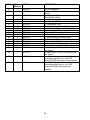
1
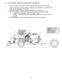
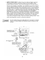
SAFETY, OPERATION, MAINTENANCE, & COMMONLY USED PARTS MANUAL Revised June 2012 Curbilder Models: MC-550, MC-650, MC-655 Under Guard Rail MC-850 MC-900 Part #35001 This manual is for the Miller Curbilder Read the contents of this Manual BEFORE putting this machine in Service. Models: MC-550, MC-650, MC-655, MC-850, MC-900 Part #35001 Table of Contents Description Page(s) General Machine Model Configuration 3-5 New Machine Assembly 6-9 SAFETY 10-14 Lifting, Tie Down and Transportation Instructions 16-19 Preparing for the Job 20-30 Choosing the Curb Form Curb Mix Information Choosing the appropriate Auger Size for a given Curb Form Choosing either a Solid or Hollow Auger Reviewing any Special Applications that can apply to your Job Site Layout of the Job Site Operating the Curbilder 20-21 21-24 24-26 29-30 31-42 Curbilder Controls and Adjustments Preparing the Curbilder for Operation Assign Crew to Work Stations Curbilder is now in position to extrude curb Curbilder Cleaning 31-40 41 41 42 43 Curbilder Maintenance 43-50 Abbreviated Parts listing 51-54 27 27-29 SPARK ARRESTER SERVICE: Your engine is not factory-equipped with a spark arrester. In some areas, it is illegal to operate an engine without a spark arrester. Check local laws and regulations. A spark arrester is available from your authorized engine dealer. 2 General Machine Model Configuration: Note: All Machines are assembled with the auger assembly on the left side of the machine except for the MC-655 Under Guardrail Curbilder which only comes with right hand assembly. On the other models you can request right hand assembly of Auger if required at the time the order is placed. MC-550 MC-650 MC-655 13 HP Honda Recoil Start w/ Recoil Backup STD Duty 13 HP Honda Electric Start w/ Recoil Backup STD Duty STD Duty STD Duty 13 HP Honda Electric Start w/ Recoil Backup STD Duty Offset STD Duty Auger Qty & 2-6” Size Auger Type Cast Solid Compaction STD Duty Tube Steel 2-6” Cast Solid STD Duty Steel Auger Housing STD Duty Steel STD Duty Heavy Steel Duty Steel Wheel/Tire Quantity and Type 8” x 2” Solid Std. Duty. Nine (9) Total. 8” x 2” Solid Std. Duty. Nine (9) Total. 8” x 2” 6-4.10 x 3.50-4 Solid Std. Pneumatic. Duty. Six (6) Total. Nine (9) Total. 3 Wheel Uprights STD Duty 8-1/2” Vertical Adjust One (1) Form Customer Choice STD Duty 8-1/2” Vertical Adjust One (1) Form Customer Choice STD Duty 8-1/2” Vertical Adjust One (1) Form Customer Choice Engine Frame Motor Mount Curb Form MC-850 MC-900 20HP Honda Electric Start w/Recoil Backup 20 HP Honda Electric Start w/ Recoil Backup Heavy Duty Heavy Duty Heavy Duty Heavy Duty 2-6” 2-6” 3-6” Cast Solid STD Duty Steel Cast Solid Heavy Duty Cast Cast Solid Heavy Duty Cast Heavy Duty Steel Heavy Duty Steel 3 Heavy Duty 19” Vertical Adjust 4-4.10 x 3.50-4 Pneumatic for Front. Four (4). 8” x 2-1/2” solid Heavy Duty for Rear. Three (3). Heavy Duty 19” Vertical Adjust One (1) Form Customer Choice One (1) Form Customer Choice Options Available: MC-550 MC-650 MC-655 MC-850 MC-900 15 HP Kohler Recoil Start 15 HP Kohler Electric Start 15 HP Kohler Electric Start N/A N/A 5” Solid CAST Standard Duty Auger Assembly with two (2) 9” Long Augers 5” Hollow CAST Standard Duty Auger Assembly with two(2) 9” Long Augers 6” Solid CAST Heavy Duty Auger Assembly with either two(2) or three(3) 9” Long Augers A A N/A A N/A A A N/A A N/A A Two (2) Augers/ Assembly 45011- 14 A Two (2) Augers/ Assembly 45011-14 N/A A Two (2) Augers/ Assembly 45011-14 Standard Equipment Three (3) Augers/ Assembly 6” Hollow Cast Standard Duty Auger Assembly with two(2) 9” Long Augers A Two (2) Augers/ Assembly 100021 A Two (2) Augers/ Assembly 100021 N/A A Two (2) Augers/ Assembly 100021 N/A 6” Hollow CAST Heavy Duty Auger Assembly with either two(2) or three(3) 9” Long Augers A Two (2) Augers/ Assembly 45011-29 A Two (2) Augers/ Assembly 45011-29 N/A A Two (2) Augers/ Assembly 45011-29 A Three (3) Augers/ Assembly 45011-86 8” Solid Fabricated Steel Standard Duty Auger Assembly with one (1) 18” Long Auger A One (1) Auger/ Assembly #100025 A One (1) Auger/ Assembly #100025 N/A A One (1) Auger/ Assembly #100025 N/A Engine 4 Options Available: MC-550 MC-650 A One (1) Auger/ Assembly 45037-15 A One (1) Auger/ Assembly 45037-15 N/A A One (1) Auger/ Assembly 45037-15 A Three (3) Augers/ Assembly 45037-30 8” Hollow Fabricated Steel Standard Duty Auger Assembly with one (1) 18” Long Auger A One (1) Auger/ Assembly 100023 A One (1) Auger/ Assembly 100023 N/A A One (1) Auger/ Assembly 100023 N/A 8” Hollow Fabricated Steel Heavy Duty Auger Assembly with one (1) 18” Long Auger A One (1) Auger/ Assembly 45037-31 A One (1) Auger/ Assembly 45037-31 N/A A One (1) Auger/ Assembly 45037-31 N/A 10” Solid Fabricated Steel Heavy Duty Auger Assembly with either one(1) 18” Long Auger or three(3) 9” Long Auger Curb Form/Mold for extruding curb over dowel pins Wheel/Tire Quantity and Type N/A N/A N/A A One (1) Auger/ Assembly N/A Three (3) Augers/ Assembly One (1) Form Customer Choice N/A One (1) Form Customer Choice 4-4.10 x 3.50-4 Pneumatic for front and rear. Six (6) total One (1) Form Customer Choice N/A One (1) Form Customer Choice 8” x 2-1/2” Heavy Duty solid, front and rear. Nine (9) total One (1) Form Customer Choice 4-4.10 x 3.50-4 Pneumatic for front and rear. Six (6) total. 8” Solid Fabricated Steel Heavy Duty Auger Assembly with either one (1) 18” Long Auger or three (3) 9” Long Auger MC-655 5 MC-850 MC-900 New Machine Assembly: 1) Remove Curbilder from Shipping Skid. 2) Loosen the two (2) Hopper Retention Bolts/ Wing nut assemblies. Unlatch the two (2) rubber hood latches on the Belt Guard which holds the Engine Cover in Place. Fold the Engine Cover into the hopper. With two (2) people, lift the hopper and engine cover off of the Curbilder frame and set these parts on the ground. Remove the Steering/Brake Handle that is shipped on the top of the Curbilder frame. 3) On Electric Start Models: A) On ALL Electric Start Models the Ignition Keys for the Engine are wire tied to the Ignition Switch on the Right side of the Engine. B) On Models MC-650, MC-655: Remove the two (2) wing nuts on the top of the Black Battery Cover on the Battery Box in the middle of the Curbilder frame. Then remove the Battery Cover. Connect the Black Ground to the Left Front Bolt Assembly holding the Battery Box to the Curbilder frame. Be sure to replace BOTH Star Lock Washers as shown to obtain a good Ground. Replace Battery Cover. Replace Hopper and Engine Cover. 6 C) On Models MC-850, MC-900: Locate the two (2) Grey Battery Cable Plugs at the Left side of the Engine. Orient the Plugs so they will connect together with the correct +/- polarity. Push the two (2) plugs together until they are fully engaged and snapped into position. Replace Hopper and Engine Cover. 4) Attach the Steering/Brake Handle to the Front Wheel Assembly on the same side of the machine that the Auger assembly is located. Use 3/8”-16NC Hex Head Cap Screw x 3-3/4” Long with Nylock lock nut. For Curbilders with Solid Front Wheels assemble the Handle in the two (2) holes in the fork of the Front Wheel Assembly toward the Rear of the machine. For Curbilders with Pneumatic Front Wheels assemble the Handle in the two(2) holes in the fork of the Front Wheel Assembly toward the Front of the machine. Tighten bolt so the Handle pivots smoothly without binding. 7 5) Attach Curb Form to the end of the Compaction Tube using three (3) ½”-13NC Hex Head Cap Screw with Split Lock Washer and Hex Nut. Then turn the “Tee” Handled Curb Form Hold Down bolt clockwise until the end of the bolt makes firm contact with the end of the Curb Form. DO NOT OVERTIGHTEN THIS “T” BOLT. 6) Fill the engine with the proper grade and amount of motor oil. Refer to the Engine Owner’s Manual. 7) Lube all grease fittings. See the “Maintenance Section”. 8 8) Reverse the Position of the Rear Wheel Assembly on the Frame of the Curbilder. The Rear Wheel Assembly is shipped with the Vertical Square Tube placed facing the Front of the Curbilder. This position prevents shipping damage. To place the Vertical Tube in the correct position for machine operation: A) Turn the Rear Wheel Assembly Crank Clockwise until the Rear Wheel Assembly is off of the ground. B) Remove the one (1) vertical Retention Bolt holding the Rear Wheel Assembly Clamp to the horizontal square tube at the rear of the machine. C) Pull the Rear Wheel Assembly and Bracket off of the square tube of the frame. D) Reinstall the Rear Wheel Assembly and Bracket to the rear of the Frame of the Curbilder sliding the Bracket over the Square Tube with the Vertical Rear Wheel Assembly facing to the REAR of the Curbilder. E) Locate the outside edge of the Rear Wheel Assembly nearest the Curb Form two (2”) from the edge of the Curb Form. F) Replace the vertical Retention Bolt in the Bracket and tighten. 9 10 SAFETY See “Operating the Curbilder,” page 30 for location of machine controls. This symbol applies to all items in the Safety section unless otherwise noted. This CAUTION symbol indicates a possibility of Personal Injury or Equipment Damage if the Instructions in this manual and on the decals attached to the machine are not followed. This DANGER symbol, when it appears, indicates a strong possibility of Severe Personal Injury or Death if the Instructions in this manual and on the decals attached to the machine are not followed. These safety and operating instructions for Miller Spreader curbing equipment are for your protection. Careless regard of these instructions and other safe construction practices could result in accidents and injury. Read and Understand this manual and ALL Decals located on this machine BEFORE putting this machine into service. A. General Safety Replace damaged or worn decals. Replace damaged or worn decals only with original equipment decals. Do not modify decals in any way. Know what safety equipment is required to operate and maintain this machine. Safety equipment must include but not limited to Safety Glasses, Reflector type Vests, Gloves, Ear Protection and Steel Toed Work Boots. Never operate or perform any maintenance on this machine while under the influence of Drugs and/or Alcohol. A qualified service mechanic using only MILLER SPREADER replacement parts or their approved equal must make all repairs to this machine. Any deviation from the original MILLER SPREADER supplied machine in the operation, repair, and/or modifications of the machine without the express written consent of the MILLER SPREADER COMPANY, voids all machine warranties and any liability for injuries and/or damage to person or property. B. Before putting this equipment into operation inspect the equipment daily. Inspect this equipment on a hard and level surface. 1. Shut engine off. “LOCK-OUT, TAG-OUT Equipment BEFORE serving. 2. Push in any one (1) Emergency Stop Switch and remove Spark Plug Wire(s) to prevent accidental starts. 3. Block wheels in both directions to prevent machine movement. Lower machine using the three (3) Wheel Height Adjustment Cranks until Auger Housing Assembly engages the ground and the Curb Machine is Immobile. 4. Inspect belt tension/chain tension. Adjust if required. See “Machine Adjustment Section”. 11 5. Inspect auger for wear. Repair or replace if required. See “Machine Cleaning and Maintenance Section”. Inspect tires, wheels and tire pressure on pneumatic tire models. Air pressure should be 30 PSI. Inspect all operating controls: Engine Speed Control Linkage, Steering Handle, Service Brake and Wheel Height Adjustment three (3) places. Inspect Safety Torque Arm Assembly for proper operation, cleanliness, and adjustment. See “Machine Adjustment Section”. Inspect engine oil level. Follow all maintenance as outlined in the “Machine Cleaning and Maintenance Section”. Before adding fuel: 6. 7. 8. 9. 10. A hot and/or running engine can ignite spilled gasoline. Shut engine off. Let engine cool off a minimum of 5 minutes Extinguish smoking materials Use funnel Do not overfill Replace fuel cap after adding fuel. Exercise extreme caution when refueling. After making Inspections and Adjustments 1-10, REPLACE ALL MACHINE GUARDS. Start engine. Verify that centrifugal clutch operates correctly. At idle speed the clutch fully Disengages auger drive and the auger stops turning. When engine speed is increased to full speed, the clutch engages and auger turns freely. Do not operate the Curbilder unless Centrifugal Clutch operates correctly. Make any necessary repairs or adjustments before putting this equipment into operation. All repairs must be made by qualified service personnel using only MILLER SPREADER replacement parts or their approved equal. Any deviation from the original MILLER SPREADER supplied machine in the operation, repair and/or modifications of the machine without the express written consent of the MILLER SPREADER COMPANY voids all machine warranties and any liability for injuries and/or damage to person or property. ALL GUARDS MUST BE IN PLACE AND FUNCTIONAL. Refer to the “Machine Cleaning and Maintenance” and Machine Adjustments Sections” of this manual. C. Familiarize yourself with the work site and job conditions PRIOR to using the Curbilder. This equipment must only be operated by trained personnel who fully understand its safe operation. Each operator must be able to identify any unsafe worksite conditions and report these conditions to his supervisor for immediate correction. Do not start or operate this equipment in an unventilated area. A GASOLINE ENGINE DISCHARGES CARBON MONOXIDE GAS WHICH CAUSES INJURY OR DEATH IF INHALED. ENGINE EXHAUST AND SOME OF ITS CONSTITUENTES ARE KNOWN TO CAUSE CANCER, BIRTH DEFECTS AND OTHER REPRODUCTIVE HARM. DO NOT OPERATE THIS MACHINE IN A BUILDING OR OTHER AREA WHERE THERE IS NOT ADEQUATE VENTILATION FOR THE OPERATOR. WHERE THERE IS ANY POSSIBILITY 12 OF INADEQUATE VENTILATION ON THE JOB DUE TO BUT NOT LIMITED TO CARBON MONOXIDE GAS, THE JOB SITE AREA MUST BE TESTED REGULARILY (EVERY ONE (1) HOUR) PER OSHA 29 CFR PART 1910.146. FURTHER, THE JOBSITE MUST MEET ALL OSHA MINIMUM ATMOSPHERE GUIDELINES FOR THE JOB SITE AS SET FORTH “IN THE SAFETY AND HEALTH REGULATIONS FOR CONSTRUCTION”, OSHA 29CFR PART 1926.55 APPENDIX A. ADEQUATE VENTILATION MUST BE DETERMINED BY FOLLOWING JOB SITE INSPECTION PROCEDURES AS OUTLINED BY OSHA. ALL JOB SITE VENTILATION ISSUES MUST BE CORRECTED BEFORE EXPOSING WORKERS TO HARMFUL JOB SITES. Do not operate this equipment on unsafe surfaces. This equipment is intended for use only on leveled and compacted surfaces. AVOID ANY CONDITIONS OF SLOPE AND/OR GRADE, WHICH CAN CAUSE THIS EQUIPMENT TO TIP. 1. Verify that all surfaces will support safely the maximum load of the machine with the payload. Refer to the Lifting/Tie Down Section” in this Manual and “ Lifting/Tie Down/ Operation” Decals Under the Engine Cover. Be aware of the maximum Gross Vehicle Weight (GVW) of Miller Curbilders when the hopper of these machines are filled with concrete/asphalt. Verify the entire surface of the job site will support the maximum GVW as listed. If job site conditions so warrant, correct deficiencies before using Curbilder. SAFETY & OPERATION SPECIFICATION CHART FOR MILLER SPREADER CURBILDER MODELS MC-550, MC-650, MC-655, MC-850, MC-900 MAX VEHICLE GVW TIRE PRESSURE (IF with PNEUMATIC) CONCRETE/ASPHALT FRONT REAR 1600 LBS 30 PSI 30 PSI 2. 3. 4. 5. 6. All surfaces must have suitable surface for good footing for the operator and machine. Wet, muddy and/or loose surfaces may cause an operator to lose his/her footing and fall. Correct job site surface deficiencies before using Curbilder. Identify all unprotected openings on jobsite and do not operate this equipment near these openings. Identify all overhead structures, electrical wires, and door openings on the jobsite. Be sure the Curbilder and Asphalt/Concrete Truck will safely pass through and under. When working on an active/in-use roadway set up safety protection for all employees and equipment as required by local codes. This safety equipment should include but is not limited to Traffic Cones, Flagmen for traffic control, Safe Access and Exit for Asphalt/Concrete Truck. Dismiss all untrained employees and bystanders from the area in which this machine will be operated. 13 D. Operation of this equipment Use caution when operating near other people and obstructions. Always look to the rear before backing up and back up slowly. Never operate Curbilder with safety torque arm out of adjustment or serious injury may result. Never feed auger with a tool that could get caught in a turning auger and strike someone. Know the two(2) ways a Curbilder Auger can be Stopped: 1) IN AN EMERGENCY: Push IN any one (1) of the Emergency Stop Switch RED Buttons on the Curbilder. On Models MC-550, MC-650 and MC-655 there are two (2) Emergency Stop Switches located on BOTH ends of the Belt Guard (Part #45010-17). On Models MC-850 and MC-900 there are two (2) additional Emergency Stop Switches located at the left and right rear corners of the machine frame. These Emergency Stop Switches have two (2) MAINTAINED POSITIONS: Pulled OUT Position, Engine/Auger will operate; Pushed IN Position, Engine/Auger will not run. Note: On all machines manufactured prior to July 2007 there is one (1) Emergency Stop Switch located on the Belt Guard and/or the engine. The operation of this switch requires that the switch be pushed in and HELD IN to stop Engine/Auger. 2) In Normal Machine On-Off Operation: Use the Engine Speed Control (Throttle) to Decrease engine speed to the slowest Idle Speed (750 RPM) to DISENGAGE the Centrifugal Clutch. Know how to operate the Engine Throttle on your machine BEFORE putting the machine into service: A) MC-550, MC-650, MC-655, built after November 2007 see page 31 of this manual and Parts Drawing #45130-01 in the complete Parts Manual, Part #35001-01. B) MC-850, MC-900 built after February 2007 see page 31 of this manual and Parts Drawing #45028-01 in the complete Parts Manual, Part #35001-01. C) MC-550, MC-650, MC-655 built between February 2006 to November 2007 Parts Drawing #45142-08. D) MC-850, MC-900 built between February 2006 and February 2007 Parts Drawing #45142-08. E) On all models of Curbilders built prior to February 2006 the Engine Speed Control is accomplished by using the throttle located on the engine. Refer to your engine manual for operation. This vehicle is not intended for the transportation of any personnel. NO RIDERS! Do not operate equipment with oily dirty gloves and/or controls. Do not operate recklessly. Careless operation causes accidents and injury. 14 If operator must leave operator’s station (standing at the steering handle) he must 1. Stop Auger from turning. 2. Shut OFF engine. Shut off engine by depressing any Emergency Stop button on the machine. 3. Lower machine using three (3) Wheel Height Adjustment Cranks until the Auger Housing Assembly engages the ground and the Curb Machine is immobile. This equipment is not intended to be towed. NO TOWING. Refer to “Lifting and Tie down Instructions” section of this manual and machine decals. Note the three (3) ways a Curbilder may be lifted and tied down and the appropriate lifting and tie down points for each method. Note the specific load ratings for chains, straps, and forklifts. Avoid all operating conditions where you, the operator, and/or other people can become trapped or pinched between the Curbilder and some other obstacle or where a Curbilder lifted by a crane etc. can fall on you or when loading the Curbilder onto a trailer. A Curbilder cannot be operated in areas with flammable or explosive atmospheres. Refer to code of Federal Regulations (OSHA.) 29 CFR Part 1910.178 to determine permissible areas where these Curbilders may be operated. Keep hands clear of auger during operation of Curbilder. Rotating auger contact can cause injury or death. Keep away! 15 Lifting, Tie Down, and Transportation Instructions All chains/straps must pull away from and to the front and rear as shown below. A Curbilder can only be lifted with a forklift when the Curbilder has first been attached to a suitable skid rated to support a minimum of 1,500#. Failure to attach the Curbilder to a skid before lifting with a forklift may result in damage to Curbilder and/or injury to bystanders. Note: An Empty Curbilder weighs between 760# and 1,140# depending on model and auger assembly. Only lift, load and tie down Curbilder with the Hopper EMPTY, the Engine Off and the Engine Fuel turned Off). A. To load a Curbilder onto a trailer: Either: Load the Curbilder using a Crane (see item C below). or Pull the Curbilder onto a trailer using ramp(s). Note: When pulling Curbilder onto a trailer, the top, loading surface of the ramp(s) must be clean and dry. The Loading Surface of the Trailer must be level, dry and the brakes on the towing vehicle secure. Three (3) people are required to pull the machine onto the trailer. Pull the machine with the Steering Handle toward the front of the trailer. Turn the Height Adjusting Screws COUNTER-Clockwise to provide 6” of clearance between the bottom of the Auger Housing and the ground. This clearance is required for the Curbilder to clear the ramp pivot point on the trailer. Also raise the Pointer Rod up so there is a minimum of 6” of Clearance between the bottom end of the Pointer Rod and the Ground. The ramps must not exceed a 25% (15 Degree) Grade. If three (3) people are not available to pull the machine onto the trailer a 1000# rated Winch is required to safely pull the Curbilder onto the trailer. 16 B. To tie Curbilder down to the Trailer Bed, Truck Bed, etc. Lower Curbilder using three (3) Wheel Height Adjusting Screws until Auger Housing makes firm contact with the trailer bed and Curbilder is level with bed of trailer and the Curbilder is immobile. Chock all wheels to prevent machine movement in all directions. Secure Curbilder to trailer bed using three (3) chains or straps as follows: 1. 1 strap at the front middle of the Curbilder frame. 2. 2 straps, 1 at each pocket formed by the tube and frame at the rear of the machine. All chains/straps must pull away and to the front and rear as shown. 17 C. To lift Curbilder To lift the Curbilder use a crane or other mechanical hoist rated at a 1,500# Working Load and: Position the chains or straps as follows: a) One (1) at the front corner formed by the motor mount and the Curbilder frame. b) Two (2) at rear corners formed by the auger housing and the Curbilder frame. Position each chain or strap in a “U” shape around the Curbilder frame. Adjust chains or straps so that when the Curbilder is lifted it is level in both length and width. Use OSHA approved lifting/tie down chains and straps that are designed to have a minimum working load limit of 2500# per chain or strap. Lift or tie down Curbilder only when hopper is empty. Only transport Curbilder with engine off. Turn fuel switch to off position to prevent fuel from entering crankcase. 18 D. To lift Curbilder equipped with optional lifting lug: To lift the Curbilder use a crane / hoist / chains rated at a 1,500# Working Load and: Position hook / chain through lifting lug eye. Note: There are two lifting lug attaching positions. If the Curbilder is set up to extrude on the left side of the machine, the lifting lug is to be attached in the left set of mounting holes. If the Curbilder is set up to extrude on the right hand side of the machine, the lifting lug is to be attached to the right set of mounting holes. Torque lifting lug mounting bolts to 60 FT LBS. 19 Preparing for the Job Choosing the Curb Form Miller Spreader has manufactured over 1600 different Curb Forms. Any of these Curb Forms are available or you may request a Curb Form to your specific dimensions. To Order a Curb Form: A. If you have an existing Curb Form locate the stamped number (one (1) to five (5) digits/letter) on the outside face of the curb form mounting flange. Submit this number to your local Miller Dealer. Be sure to note any special features your Curb Form can have, for example, does it operate over dowel pins, will it extrude 3/8” (#3) reinforcing rod rebar through the center of the auger shaft, etc. B. If you have a drawing with dimensions or a full size tracing of the exact shape of the curb form you want to purchase, submit this information to the Miller Spreader Company. Be sure to note any special features your Curb Form can have, for example, does it operate over dowel pins, will it extrude 3/8” (#3) reinforcing rod rebar through the center of the auger shaft, etc. The Miller Spreader Customer Service Department will try to match your Curb Form information with our listing of previously manufactured forms. If your Information matches a form made previously, the number and drawing of this form will be sent to you. If the form has never been made a new Curb Form Design (CFD) Number will be assigned. C. For Curb Forms in which the shape is non-symmetrical (Drawing a vertical center line down the center of a Curb Shape, the left and right halves of the Curb Form Shape are not the same) a left or right hand Curb Form must be determined. To determine Curb Form Hand for non-symmetrical Curb Forms: i. Imagine a Curbilder equipped with the desired curb form to be in operation moving AWAY from an observer at the rear of the machine (where the curb comes out). See drawing below. 20 ii. With an observer looking at the Curbilder as shown determine from the observer’s viewpoint on which side (left/right) the most vertical side of the curb is being formed. The location of the most vertical side on the Curb Form determines the hand of the form. For example, if the most vertical side of the curb is on the observers left side, the curb form required to extrude the curb should be designated as a left-hand form. Note: The majority of Curb Forms (over 90%) are manufactured as Left Hand. Curb Mix Information Determine the mix design and select a material supplier. Because available mix and job conditions will vary from one area to another, the following concrete and asphalt mix specifications can be used as guides to determine exact mix requirements for your application. General Conditions that apply to all Mixes: All Aggregates must be thoroughly washed in order for either the cement or asphalt to bind properly to the aggregate. Moisture content in the aggregate will affect mix performance. A lot of rain water in any aggregate used in making concrete will increase mix slump. Aggregates used to manufacture asphalt mixes must be dry (less than 5% moisture by weight) or the steam created in the mix will prevent sufficient mix density. Wet Aggregates will prevent asphalt from sticking to the aggregates and cause steam, which will compromise curb density. TEST THE MIX BEFORE USING. The same mix formula in different geographic areas will have somewhat different results on the job site. Avoid Mix surprises on the job site. Some Mix adjustments are required when using different curb forms and auger sizes. Tall, narrow, molds need lower slump (less than 1”) or less heat (asphalt mixes, less than 275 Degrees F). Larger molds (using 8” or 10” augers) can use larger stone (up to ¾”/ #57). Avoid Curb Mixes with excessive amounts of sand and fine aggregates (less than 3/32”/ #8 sieve). These types of mixes can have a very smooth surface requiring little if any finishing. However, the lack of larger stone results in a weak curb. And a high concentration of fines will cause High Wear on the auger, compaction tube and curb form. Furthermore, a high concentration of fines has an excessive amount of surface area requiring greater amounts of Portland Cement or Asphalt to provide proper adhesion. Mixes with high concentrations of fines can also result in slower machine speeds because of the “slip” of the fines past the auger. 21 A. Concrete Curb Mix: 1) Components of One(1) Cubic Yard of Concrete Curb Mix: a) Cement: Use Portland Cement. Typically, Concrete Curb Mixes use 6 to 7 sacks/564-660# of Portland Cement per cubic yard. A higher concentration of cement is required because of the greater surface area of the smaller aggregates used in this mix. When desired, certain Mineral Admixtures can be substituted for some but not all of the Cement in the mix. These Admixtures include Fly Ash or Ground Granulated Blast Furnace Slag (GGBF Slag). Consult the job specifications and your local concrete plant to determine what allowances are possible for these Admixtures. b) Water: Water used in the mix must be clean and clear. Potable/Drinkable water is best but not required. Between 25 to 40 gallons of water per cubic yard will produce 1-2” slump depending on the moisture content already in the aggregate. Let the concrete plant know what slump you need when the Mix is DELIVERED to the job site. They will make allowances for the moisture content in the aggregates and travel time. c) Aggregates: Crushed aggregates produce stronger Curb Mixes and have better standing properties when extruding taller curbs than smooth river stone. A good starting point is an aggregate blend having 60% sand and 40% stone. Sand: Use Concrete sand blend with 100% passing a #8/2.4 mm Sieve. Stone: Use Stone with 100% passing a 3/8”/9.5 mm sieve. When extruding curb forms with 8” or 10” augers some of the 3/8” stone can be replaced with larger stone up to ¾”/#57. If excessive voids appear in the Mix, reduce the size of the larger stone (not the %) until the curb surface improves. d) Admixtures: Note: Consult the job site specifications to determine requirements/allowances for admixtures. 1) Air Entraining Admixtures: Adds durability to Concrete Curb exposed to cold weather and road salt. 2) Retarding Admixture: Slows down the early hardening of concrete. Extends workability/finishing time. 3) Water Reducing Admixture: Reduces the amount of water and cement required to achieve a given slump in the concrete. The use of this admixture can increase the strength of the concrete. 2) A recommended mix design for one cubic yard of concrete: Cement: Sand: Aggregate: Water: 660# (7 sacks) 1,600 #, 5% moisture 1,400 #, 3/8" Approximately 25 gallons/ 1” Slump 22 Keep loads to 3-5 yards when possible. Water content required to maintain slump will vary according to moisture content in the aggregate. Larger loads and/or higher air temperatures may require more water to maintain slump. Add water at job site only. Work materials to dry side. Retardant admixture should be used at the manufacturers recommended minimum amount. This amount may be adjusted based on local conditions. Air entrainment should be added at approximately 5%. This amount may be adjusted based on local conditions. B. Asphalt Curb Mix: 1) Components of One (1) Ton of Asphalt Curb Mix: a) Liquid Asphalt: Asphalt Content should be 6.0 to 9.0% by weight of total mix Liquid Asphalt should be AC-20 or AR-8000 (60-70 penetration). The liquid asphalt content will also have to be raised if the mix has slag, or other absorptive materials in it. b) Aggregates: All aggregates must be heated and dried. Crushed aggregates produce stronger Curb Mixes and have better standing properties when extruding taller curbs than round river stone. A good starting point is an aggregate blend having 60% sand and 40% stone. When extruding curb forms with 8” or 10” augers some of the 3/8” stone can be replaced with larger stone up to ¾”/ #57. If excessive voids appear on the surface of the extruded curb, reduce the size of the larger stone (not the %) until the curb surfaces improves. Aggregate graduation SIEVE SIZE ½” 3/8” No. 4 No. 8 No. 50 No. 200 PASSING % BY WEIGHT 100 75-100 60-80 45-60 18-30 2-15 c) Temperature: optimum working temperature needs to be 250 to 290 degrees Fahrenheit. Under no circumstances should mix temperatures exceed 300 Degrees F. 23 C. Mix required for a given Curb Form Use the following calculations to help determine the quantity of mix required for any given curb form. It is usually a good practice to reduce yield per cubic yard/per ton by 5% to allow for waste, shortages, etc.: CONCRETE: 3,888 = lineal feet of curb per cubic yard Area of curb form in Square Inches ASPHALT: 1920 = lineal feet of curb per ton Area of curb form in Square Inches NOTE: Contact Miller Spreader Customer Service to obtain the Curb Form Design Sheet for the Curb Form you are using to obtain the square inch area of the curb form. Choosing the appropriate Auger Size for a given Curb Form Curbilders can be equipped with one of four (4) different extrusion auger assembly sizes. These sizes are a nominal 5”, 6”, 8”, and 10” in diameter. Note: The 10” diameter auger is designed to work on the MC-850 and MC-900 Curbilders only. The square inch area and height of a curb form design are to a large degree, but not solely, determine which auger assembly size is correct for any given curb form. For purposes of initially matching an auger size to a particular curb form use the curb form area: Curb Form width X height less the area of sloped side(s). Exceptions to this guideline will be noted at the end of this section. The following examples will help you determine the correct auger size to use with a curb form. Please refer to the following chart. Auger Size 5” 6” 8” 10” Min Sq Inch Area 18 33 56 120 Max Sq Inch Area Min Height 32 55 119 220 3” 4” 6” 8” Max Height 6” 10” 18” 18” Min Width 5” 6” 8” 10” Max Width 9” 14” 18” 18” The area of each curb form is available from the Miller Spreader Company. Locate the stamped number (one (1) to five (5) digits/letter) on the outside face of the curb form mounting flange. Contact the Customer Service department with this number and a Miller service representative can supply the area for that curb form. You can consult the factory for curb form and auger size recommendations. IMPROPER SELECTION OF THE AUGER SIZE FOR A CURB FORM CAN CAUSE EXCESSIVE COMPONENT WEAR, POOR MACHINE PERFORMANCE AND/OR THE COMPLETE FAILURE TO OPERATE. 24 Examples of choosing an auger size for a given Curb Form Example #1 The curb form to be used is Curb Form Design (CFD) #14. The area of this curb form is 38.9 square inches and the overall height of this curb form is 6”. Referring to the chart above see the area of #14 curb form falls within the 33 to 55 square inch recommended range of a 6” diameter auger. Then see that both the height and width of this curb form also fall within the recommended range for a 6” diameter auger. For best results in terms of both production and curb quality a 6” diameter auger is recommended. CFD # 14 Area 38.9 SQ IN Auger Size 6 ” 95 Linear Feet per CU YD of concrete 50 Linear Feet per Ton of Asphalt 25 Example #2 The curb form to be used is Curb Form Design (CFD) CFD # 1021 Area 25 SQ IN #1021. The area of this curb form is 25 square inches Auger Size 5 ” and the overall height of this curb form is 4”. Referring 140 Linear Feet per CU YD of concre to the chart above see the area of #1021 curb form falls 78 Linear Feet per Ton of Asphalt within the 18 to 32 square inch recommended range of a 5” diameter auger. Then see that both the height and width of this curb form also fall within the recommended range for a 5” diameter auger. Because the height and width of this curb form also fall within the recommended height and width range of a 6” diameter auger the temptation might be to use a 6” diameter auger to achieve greater production/speed. However, for best overall results in terms of production, life of wear parts and curb quality, a 5” diameter auger is the better choice. The most common mistake in sizing a curb form to the correct auger size is choosing a curb shape, which is too small for a particular auger. In example #2, the previously mentioned curb with an area of 25 square inches would work well with a 5” diameter auger assembly, but would most likely not work at all with a 6” diameter assembly. The amount of material discharged by the 6” diameter auger into the curb mold would be so great in relation to the curb size that the mold would not be able to discharge or extrude the material fast enough. In effect, the mold becomes a “BOTTLENECK.” As a result, excessive pressure will be created inside the form. When the density of the material in the curb form reaches the point where it can be compacted no further, the excessive pressure in the form will be transmitted back through the drive train, causing repeated disengagement of the safety torque arm, raising up of the curb form and/or shear bolt breakage. To avoid the problem, the auger size must be reduced or the curb form size increased. The second problem in sizing curb sections to auger sizes is choosing a form that is too large for a particular auger. An undersized auger can discharge enough material to propel the machine, but the curb produced will have inadequate density, a curb surface full of voids and/or a curb that will not stand up. In the most severe cases of an undersized auger, the auger will not discharge enough material to propel the machine. An undersized auger can be corrected by either increasing the auger size or by reducing the curb form area. Possible exceptions: If the curb form size is within 5-10% the recommended ranges in either upper or lower limits in the chart above the curb form may operate with the mix in your area. Only tests with local mixes will confirm satisfactory performance. Be aware that operating a Curbilder with an auger size OUTSIDE of the recommended limits can cause excessive wear and/or insufficient curb density. THE CUSTOMER ASSUMES ALL PERFORMANCE AND WEAR ISSUES WHEN OPERATING THE CURBILDER WITH AN AUGER OUTSIDE THE RECOMMENDED RANGES. 26 Choosing either a Solid or Hollow Auger Auger assemblies can be provided as “HOLLOW” assemblies allowing the insertion of 3/8” (#3) reinforcing rod into the curb during the extrusion process, or as “SOLID” assemblies for curbing without rebar. Determine which type of auger is required for your job site. The augers that are mounted onto a solid auger shaft have one (1) long shear bolt through the center of each auger. The augers that are mounted onto a hollow auger shaft have two (2), short, specially machined shear bolts which engage each side of the shaft but do not interfere with the rebar. Note: Hollow Auger Assemblies can only be mounted on the LEFT side of the Curbilder. Reviewing any Special Applications that can Apply to your Job Site A. Placing Reinforcing Rod/Rebar in an Extruded Curb With a hollow auger assembly (available for 5”, 6” and 8” diameter augers) a 3/8” diameter steel reinforcing rod can be inserted through the center of the Optional Hollow Shaft Assembly. The Front Wheel Support must be moved away from the LEFT side of the frame on which the Auger housing is mounted so that a special bracket can be mounted to the front of the frame to guide the rebar into the Hollow auger Shaft. The machine operator inserts reinforcing rod in 10’ lengths into this bracket. From the bracket the rebar then passes into the Hollow Shaft during the curbing operation. The rod passes through the auger shaft and curb form and into the finished curb. For radius work stranded steel aircraft cable can be used. When choosing a curb form to be used with reinforcing rod, curb height and configuration are important considerations. As much material as possible should surround the rod within the finished curb. The location of the rod from the ground is fixed for each auger size. Therefore, it is important to have sufficient curb form height to adequately cover the rod. With a 5” auger assembly, the top of the reinforcing rod will be approximately 3-1/2” above the ground. With a 6” auger assembly, the top of the reinforcing rod will be approximately 4” from the ground. With an 8” auger assembly, the top of the reinforcing rod will be approximately 5” from the ground. A minimum of 1” and preferably 2” of material should be on top of the reinforcing rod. 27 B. Extruding Curb over vertical Dowel Pins With a Miller Curbilder, curb can be extruded over vertical dowel pins. This is accomplished by raising the machine with the leveling screws at each wheel assembly in order to allow the screw housing to pass over the pins. Curbing over dowel pins also requires a special curb form. The form must be made with an elevated auger opening to accommodate the raised auger assembly. It must also incorporate an opening at the bottom of the mounting flange to allow the pins to pass into the form as the machine moves over them. Curb forms for curbing over pins are made for a specific pin height. Therefore, the pins cannot exceed the pin height that the curb form was designed for. Also, pin placement is critical. Pins must be on line, not more than ½” left or right of center to prevent pins from hitting the form. The most important aspect to remember when considering curbing over pins is that there must be a minimum of 5” between the top of the finished curb and the top of the pin. For example, to curb over 1” pins, the curb height must be 6”; over 2” pins, the curb height must be 7”; over 3” pins the curb height must be 8”. In most cases, the Curbilder cannot extrude rebar and pass over pins at the same time. C. Extruding Curb Under an existing Guardrail A Miller Curbilder Model MC-655 has an offset frame, auger housing and hopper so that asphalt curb can be placed under existing guardrail. Supply the Miller Spreader Customer Service Department a drawing showing the curb form shape and the guardrail dimensions under which the curb must be placed. Our Customer Service Department will evaluate the feasibility of your job your application. D. Extruding New Curb over Old Curb A Miller Curbilder can extrude new curb over old curb. A special curb form is required. Roads that have several layers of pavement built up against the curb will diminish the curb height. Extruding new curb over the old can increase the curb height. To build this special curb form, both the old curb form design and the new curb form design are required. Consult with the factory about your specific requirements. E. Extruding Curb into an Offset Ditch A Miller Curbilder can extrude a new curb into an excavated ditch/trench at the edge of a paved road surface. A special curb form is required. There are some limitations to this procedure depending on curb size, the amount of offset required and the distance to the 28 bottom of the ditch/trench. Supply the factory the curb form shape, the amount of offset and the depth of the ditch/trench from the top of the road surface to determine the feasibility of your application. Layout the Job Site Before putting the Miller Curbilder in use determine the location of the curb on the job site. Work from either plan job site drawings or surveyors grade stakes. A) Determine the SEQUENCE or ORDER in which each curb section will be placed. Consider the hand(s) (Left and/or Right) of Curb Forms required, the exit areas available at the end of straight sections and the starting locations of curbs required against walls and other curbs. Anticipate the best sequence of moves for the concrete trucks. Note the location of unprotected openings, walls, excavations, etc. Also note the location of any overhead wires, openings or obstructions that will affect the curb placement sequence. Note any job conditions that are unsafe and take corrective action BEFORE putting the Curbilder into service. For example, correct any soft condition in base or exit areas. All surfaces where the Curbilder must travel must be leveled within a 5% slope and compacted in excess of 90%. DO NOT OPERATE THE CURBILDER ON SOFT, UNEVEN SURFACES WHICH CAN CAUSE THE CURBILDER TO GET STUCK AND/OR TIP. Job site grades must not exceed 15%/ 8.5 Degrees. Dangerous Job Site Conditions that will be present during curb placement must be marked and protected with sufficient equipment to prevent any injury to personnel. Examples include but are not limited to overhead wires, openings with more than a 6” drop off, other job site work activity, etc. B) Determine the LOCATION where each curb section will be placed. Mark all the locations of the inside curb face. The inside curb face is the face/side of the curb that faces toward the middle of the road or toward the center of a parking area. Then snap a chalk line or nail in place a colored string 12” from the location of the inside face of the curb toward the center of the road/parking area. This mark/string will be the reference for the pointer on the front of the Curbilder. C) Apply Adhesive. i) ii) iii) When placing Concrete Curb over an existing concrete surface, apply a spray coating of Concrete Epoxy to the area where a concrete curb will be located on top of a concrete surface. Permit the epoxy to become tacky before applying curb. Follow epoxy directions for curing, amounts to be placed and safety. When placing Concrete Curb over an existing asphalt or compacted rock surface apply a spray coating of SS-1 Emulsified Asphalt Tack Coat to the area where a concrete curb will be located. Apply from .05 to .15 gallons per square yard. When placing Asphalt Curb over an existing asphalt, concrete or compacted rock surface apply a spray coating of SS-1Emulsified Asphalt Tack Coat to the area where a concrete curb will be located. Apply from .05 to .15 gallons per square yard. 29 30 Operating the Curbilder A. Know how to Use and Adjust ALL Controls and Features of the Miller Curbilder BEFORE putting this machine into Operation. 31 ENGINE: Review the Engine Manual. Know how to SAFELY start, stop and add fuel to the engine. ENGINE THROTTLE: Locate the Engine Throttle on your engine. Refer to page #13 in the Safety Section On throttle operation. Know how to increase engine speed to engage the centrifugal clutch and auger. Know how to decrease engine speed to disengage/ STOP the clutch and the auger. MACHINE HEIGHT: The machine height of the Miller Curbilder can be adjusted using three (3) crank handles located on the top of each Height Adjusting Screw Assembly, two (2) in the front of the machine, one (1) in the rear of the machine. Turn the crank handle CLOCKWISE (as looking down on the handle) to LOWER the machine height. Turn the crank handle COUNTER-CLOCKWISE to RAISE the machine height. 32 STEERING: The Steering Control of the Miller Curbilder is done by means of a Steering Handle, which can be, attached either to the Left or Right front wheel fork. BRAKE: The Steering Handle is equipped with both a Service Brake. Push DOWN on the Steering Handle to apply the Service Brake against the front wheels. FRONT WHEEL SUPPORT: The Front Wheel Support of the Curbilder can shifted to the Right or Left of the machine main frame to keep the front wheels from tracking in the asphalt tack coat or concrete epoxy. To adjust the Front Wheel Support loosen (but DO NOT REMOVE) the two (2) bolts holding the Front Wheel Support in position. Then loosen (but DO NOT REMOVE) the one (1) bolt assembly that holds the Pointer Rod in position. For Curbilder Models MC-550, MC-650 and MC-655: 1) Place the Curbilder on a LEVEL concrete or asphalt surface. Block the Wheels in both directions. 2) Raise the front of the machine high enough to place two (2) jack stands rated at 1000# each under the front of the frame. See drawing. 3) Lower the Curbilder onto the jack stands. Then raise both front wheels one (1”) inch above the ground. 4) With the machine secure on the jack stands and the bolts holding the Front Wheel Support loosened, push the Front Wheel Support in the direction desired. DO NOT STRIKE THE FRONT WHEEL SUPPORT WITH A HAMMER. Position the wheel closest to the curb form approximately two (2”) inches from the inside edge of the Curb Form. 5) Tighten the Two (2) bolts holding the Front Wheel Support. 6) Raise the machine enough to clear the jack stands. 7) Remove the jack stands and lower the machine onto the ground. 8) Leave the Pointer Rod Assembly loose until the Curbilder is in position to place curbing. Then tighten in position as required. 33 For Curbilder Models MC-850 and MC-900: 1) Place the Curbilder on a LEVEL concrete or asphalt surface. Block the Wheels in both directions. Leave the Front Wheels on the Ground. 2) With the machine secure on a level, hard surface and the two (2) bolts holding the Front Wheel Support loosened, push the Front Wheel Support in the direction desired using the Pry Bar supplied with the machine. Place the flat end of the pry bar in any slot in the Front Wheel Support and engage another slot in the angled bracket in the front of the frame of the machine. Push the Front Wheel Support with the pry Bar in the direction desired. Repeat this action until the wheel closest to the curb form is approximately two (2”) inches from the inside edge of the Curb Form. DO NOT STRIKE THE FRONT WHEEL SUPPORT WITH A HAMMER. 2) Tighten the Two (2) bolts holding the Front Wheel Support. 3) Leave the Pointer Assembly loose until the Curbilder is in position to place curbing. Then tighten in position as required. 34 REAR TAIL WHEEL ASSEMBLY: The Rear Tail Wheel Assembly consisting of the Holding Bracket and Vertical Upright Tube with wheels should be mounted with the Holding Bracket and Vertical Tube to the Rear of the Main Frame Rear Cross Tube. To adjust the LATERAL LOCATION of the Rear Tail Wheel Assembly turn the crank handle CLOCKWISE until the rear wheels are 1” above the ground. Then loosen the one (1) 3” long vertical retention Bolt on the Holding Bracket to move the Rear Tail Wheel Assembly. Slide the Rear Tail Wheel Assembly to the Left or Right so that the wheel closest to the curb form is no closer than 2” from the inside edge of the curb form. Tighten the one (1) vertical retention bolt. Note: When the Curb Form to be used is over 10” tall the Rear Wheel Outer Upright Tube can be repositioned vertically down to gain additional height of the frame of the Curbilder. To Adjust the VERTICAL HEIGHT POSITION of the rear of the Curbilder frame upward, raise the rear of the Curbilder frame as shown using the Rear Tail Wheel Assembly. Insert two(2) jack stands under the rear of the Curbilder frame. Loosen and remove the two (2) 3-1/2” long horizontal retention bolts on the Holding Bracket. Then LOWER the Rear Tail Wheel Outer Tube by turning the crank handle CLOCKWISE and at the same time pushing this tube down until the slots in the next lower tube position can be lined up with the square holes in the Rear Tail Wheel Bracket. Each lower slot position gains 2-1/4” vertical rear height of the Curbilder. When the desired position is achieved, replace and tighten the two (2) horizontal retention bolts. Remove jack stands. 35 SAFETY TORQUE ARM: The Safety Torque Arm holds the Gearbox and Input Pulley/Sheave in position to maintain the tension on the Drive Belts. When properly adjusted, the Safety Torque Arm will disengage the Drive Belts when a the drive in the Curbilder is overloaded. This overload can occur when a piece of oversize aggregate passes through the auger and/or the curb form is too small for the auger selected. The Safety Torque Arm Spring must be 2” overall length when the Safety Torque Arm Handle is pushed down in the operating position. Refer to the drawing below. To Adjust the length of the Safety Torque Arm Spring push the handle in the down position. Then turn the adjustment nut CLOCKWISE to DECREASE the spring length, COUNTER-CLOCKWISE to INCREASE the spring length. To adjust tension on the Drive Belts, lift the Safety Torque Arm Handle up. Push the Safety Torque Arm DOWN until each belt deflects 3/16” when a force of 6.7# is applied to the middle of the belt span. Hold this tension on the Safety Torque Arm and engage the Safety Torque Arm Handle by pushing it down. A belt tension adjusting gauge can assist in making this adjustment. DO NOT OPERATE MILLER CURBILDER WITH THE SAFETY TORQUE ARM OUT OF ADJUSTMENT OR SERIOUS INJURY OR DEATH CAN OCCUR. 36 POINTER ROD: The Pointer Rod is located in the Front of the Curbilder. The operator who is steering the machine while curb is being placed uses the Pointer Rod to follow a chalk or string line on the ground to place the curb in the correct location on the job. When the Curbilder is in the correct position to begin placing the curb and the chalk or string line has been placed on the ground (see 6, “Laying Out the Job Site” above) adjust the Pointer Rod 1” above the ground and directly over the reference string. Then tighten the retention bolt. To avoid damaging the Pointer Rod when loading the Curbilder onto a trailer or lifting the machine with a crane, loosen the retention bolt and lift the Pointer Rod bottom end 6” or more above the ground. Note: The Pointer Rod is assembled at the factory on the front of the Front Wheel Support. When it is required to move the Pointer Rod to the front of the Curbilder Frame a SHORTER retaining bolt is required. See drawing below for the correct bolt size for each location for each Curbilder model. Caution: Do not use a bolt length other than what is specified or the bolt will not tighten all the way and/or there will be interference between the bolt and other parts. EMERGENCY STOP SWITCH(ES): Refer to the “SAFETY” section of the manual, “Operation of this Equipment”, E.1. and “Operating the Curbilder,” page 29. Locate ALL of the Emergency Stop Switch(es) on your machine. In the event of an Emergency, know how to stop the Engine/Auger on the Curbilder using these switch(es). 37 INSTALL THE CURB FORM WITH THE CORRECT AUGER SIZE: Refer to “Preparing for the Job”, Section #1 “Choosing the Curb Form” and Section #3 “Choosing the appropriate Auger Size for a given Curb Form.” Determine which side the Auger Housing Assembly and Curb Form are to be mounted on the Curbilder. To assemble an Auger Housing Assembly and Curb Form to the Frame of a Curbilder: 1) Place the Curbilder on a level, concrete or asphalt surface. Chock the wheels as shown. Push in any one (1) Emergency Stop Switch and remove the Spark Plug Wire(s) to prevent an Accidental Start. 2) Loosen the Wing Nuts on each of the two (2) Hopper Retention Bolts and swing the bolts out of the slots in the hopper flanges. 3) Remove the Hopper from the machine. 4) Remove the Chain Guard attached to the frame with two (2) 3/8”-16NC Bolts. 5) Loosen and remove the one (1) Retention Bolt Assembly from the Chain Tension Idler. Then remove the Chain Tension Idler. 6) Raise the Curbilder up by turning the cranks COUNTER-CLOCKWISE on the three (3) Uprights. Raise the Curbilder high enough so that the Auger Housing Assembly can be slid under the frame of the machine and into the approximate mounting location. Note: The Lugs on the top of the two (2) vertical mounting flanges of the Auger Housing should be pointing toward the front of the machine with the open end of the auger pointing toward the rear of the machine. Position the two (2) vertical mounting flanges approximately ½” to the rear of the two(2) frame cross rails to which they will attach. 7) Lower the machine so that the four (4) mounting holes on the frame cross rails are level and in line with the four (4) mounting holes in the vertical mounting flanges of the Auger Housing. 8) Slide the Drive Chain onto the Drive Sprocket attached to the Output Shaft of the Gearbox and the Driven Sprocket attached to the shaft on the Auger Housing. 9) Slide the Auger Housing Assembly forward until the two(2) vertical mounting flanges of the Auger Housing are flush against the two(2) mounting cross rails of the frame. Then line up the four (4) mounting holes of the Auger Housing with the holes in the frame. Attach the Auger Housing to the frame with four (4) ½” Bolts, Lock Washers, Flat Washers and Nuts. Note: Face the four (4) bolt heads toward the Middle of the machine. 10) Reattach the Chain Tension Idler. Refer to the drawing for the correct position of the Idler. Note: When assembling the Chain Tension Idler to the frame of the machine the long leg of the attaching bar always faces UP. When attaching an Auger Assembly to the LEFT side of the Machine (standing at the rear of the machine looking forward) the Idler Sprocket engages the LOWER SIDE of the bottom leg of the chain and pulls up against the chain. When attaching an Auger Assembly to the RIGHT side of the Machine the Idler Sprocket engages the TOP SIDE of the TOP leg of the chain and pushes down. Adjust the tension on the Chain using the Chain Tension Idler Assembly so there is 3/16” Slack in the middle of the chain span. Torque the Chain Tension Idler Bolt to 60 LBS. FT. Torque. 38 11) Check the Alignment of all three (3) sprockets using a straight edge. Adjust Driver and/or Driven Sprockets so that all sprockets are in line +/-1/32” 39 12) Reattach the Chain Guard. 13) Assemble the Deflector in the correct position in the bottom of the Hopper for the Auger size selected. 14) Install the Hooper in the machine sliding the bottom opening of the hopper into the top opening of the Auger Housing Assembly. Secure the hopper to the frame by swinging the two (2) Hooper Bolts into the slots in the Hopper Flanges. Tighten both Wing Nuts on the Hopper Bolts. 15) Attach the Curb Form to the flanged end of the Compaction Tube using three (3) ½”-13NC Bolts, Lock Washers and Nuts. Then turn the “T” bolt over the end of the Curb Form CLOCKWISE until the end of the bolt makes firm contact with the end of the curb form. DO NOT OVERTIGHTEN THIS “T” BOLT. See page 8, item #5 for drawing. 40 B. Preparing Curbilder for Operation Spray inside of hopper, compaction tube, and form with No. 2 fuel oil or kerosene when extruding asphalt curb. Spray with water when extruding concrete curb. Position Curbilder so that the inside face of the curb form is in the proper location to begin extrusion. Curbilder should start from 12” - 18” ahead of where curb is to begin. Inspect the front wheel assembly horizontally to make sure the front wheels will not track in the adhesive. Adjust Rear Wheel Assembly vertically so that the discharge (rear) end of curb form just touches the base course. Adjust both Front Wheel Assemblies vertically to lift the flange (front) end of the Curb Form 1/8” to ¼” above the base course. (Rear discharge end of curb form will touch base, front flanged end of curb form will not). Set guide pointer directly over chalk/string line approximately 1” above pavement. C. Assign Crew to Work Stations A crew of three(3) is required to run Curbilder if using concrete. One person is required to steer machine and apply brake when required. A second person is needed to tend the hopper and break up any material that bridges over the auger. This person will need to adjust machine height as required. A third person is required to provide signals to the concrete truck driver and to feed concrete material into the hopper using the chute of the truck. A crew of two (2) is required to run Curbilder if using asphalt. One person is required to steer machine and apply brake when required. A second person is needed to tend the hopper and break up any material that bridges over the auger. This person will need to adjust machine height as required. An additional two to four persons will be required to bring asphalt to the Curbilder using wheelbarrows unless a Curbloader is used in which case one (1) additional person is required. Assign one or two finishers to detail curb and cut expansion joints (concrete curb only) if required. 41 D. Curbilder is now in position to extrude curb. Start engine and idle five (5) minutes. When ready to extrude curbing, increase engine speed to full throttle (3,000 RPM) to engage automatic clutch, thereby driving the extrusion auger. DO NOT RUN CURBILDER AT PARTIAL THROTTLE OR DAMAGE TO CENTRIFUGAL CLUTCH WILL RESULT. Fill hopper slowly with curb mix and allow curb form to fill. Feed Hopper of Curbilder with asphalt using wheelbarrows or Curbloader. Feed Hopper of Curbilder directly from concrete truck using discharge chute. As material nears the discharge end of the curb form, block the opening in order that the material will be compacted. (A piece of wood or a flat shovel work well.) The Curbilder starts moving forward as material is extruded through the curb form. THE FORCE OF EXTRUSION PROVIDES PROPELLING POWER. After Curbilder moves forward, the curb may be struck off with a shovel at the desired starting point. (This excess material may be reused in the Curbilder). If advanced start is not possible, starting end of curb may be hand shaped with finishing trowel. Fill hopper with curb mix at a steady rate. It is best to operate the Curbilder at a steady rate with as few of stops/starts as possible. Steer Curbilder keeping the pointer on the chalk line/string. Optimum compaction has been designed into the Curbilder and the curb form. Greater compaction will be obtained when the machine is operating uphill, when the brake is applied, or by raising the front wheel assemblies, transferring weight to the curb form. Lowering the front wheel assemblies decreases compaction by decreasing the weight carried on the curb form. When the Curbilder is not extruding material, throttle engine down to disengage automatic clutch so the auger stops turning and machine vibration does not break apart curb. Never allow material to stand in the hopper when the Curbilder is not in operation. Finish out the material in the hopper, raise the machine 1” above the curb and shut the machine off if there will be a five (5) minute or longer wait until the next truck arrives. If the wait on the next truck will be longer than 30 minutes pull the Curbilder forward until the end of the curb form clears the extruded curb. Then lightly spray the hopper and the inside of the curb form with either fuel oil or water, depending on the curb mix used. At the end of a run, cut off curb with a shovel and finish with hand trowel as required. The excess material may be reused if needed. Elevate the machine approximately 4-5” using the three (3) crank adjustments (Two(2) in Front, One(1) in Rear) and pull the Curbilder away from the fresh curb. 42 Curbilder Cleaning CLEAN THE MACHINE EVERYDAY AS OUTLINED. FAILURE TO CLEAN THE MACHINE EVERYDAY WILL RESULT IN THE AUGER SEIZING TO THE SHAFT, OTHER DAMAGED PARTS AND AN UNSAFE MACHINE. BEFORE CLEANING CURBILDER: 1) SHUT ENGINE OFF. 2) PUSH IN ANY ONE (1) EMERGENCY STOP SWITCH AND REMOVE SPARK PLUG WIRE(S) TO PREVENT ACCENDENTIAL STARTS. 3) PLACE MACHINE ON A LEVEL CONCRETE OR ASPHALT SURFACE. BLOCK WHEELS IN BOTH DIRECTIONS AND LOWER THE CURBILDER USING THREE (3) WHEEL HEIGHT ADJUSTING SCREWS UNTIL THE AUGER HOUSING MAKES CONTACT WITH THE GROUND AND THE CURBILDER IS IMMOBILE. A) To clean the Curbilder after using Asphalt, remove the curb form, compaction tube, and extrusion auger. Wash and spray parts with No. 2 fuel oil or kerosene. Spray inside of hopper with No. 2 fuel oil or kerosene. Scrape off all asphalt, which adheres to any operational surfaces. Inspect auger for wear, reverse or rebuild as required. After cleaning, grease auger shaft before placing the auger back onto shaft. B) To clean the Curbilder after use with Concrete, remove the curb form, compaction tube, and extrusion auger. All parts should be cleaned with water and all deposits scraped from Curbilder. The inside of the hopper and the auger housing should be thoroughly cleaned with water, and the auger shaft should be greased, before placing the auger back onto shaft. For long term storage spray all wear parts with a light protective coating of No. 2 fuel oil. Curbilder Maintenance Perform all Maintenance items per the schedule below. A Clean, Properly Lubricated and Adjusted machine is a SAFE MACHINE. Failure to perform Machine Maintenance as outlined can cause Injury or Death. Further, failure to perform Maintenance as outlined will cause damaged parts and unsatisfactory machine performance. BEFORE MAINTAINING CURBILDER: 1) SHUT ENGINE OFF 2) PUSH IN ANY ONE(1) EMERGENCY STOP SWITCH AND REMOVE SPARK PLUG WIRE(S) TO PREVENT ACCENDENTIAL STARTS. 3) PLACE MACHINE ON A LEVEL CONCRETE OR ASPHALT SURFACE. BLOCK WHEELS IN BOTH DIRECTIONS AND LOWER THE CURBILDER USING THREE (3) WHEEL HEIGHT ADJUSTING SCREWS UNTIL THE AUGER HOUSING MAKES CONTACT WITH THE GROUND AND THE CURBILDER IS IMMOBILE. 43 Failure to perform Machine Maintenance as outlined Voids all Machine Warranties AND any liability for injuries and/or damage to person or property. Maintenance Area Every Day or Every 5 Days or Eight (8) Hours Fifty (50) Hours of use, whichever of use. is less. Engine: Check Oil Level X Change Engine Oil X Lube Throttle Linkage Pivot Points X Bearings: Grease Two(2) Flange Bearings for Auger Shaft. Grease Three(3) Upright Jack Assemblies Grease Two(2) Flange Bearings for Gearbox Output Shaft Grease Two(2) Tie Rod End Bearings Grease All Wheel Bearings X X X X X 44 Every 20 Days or Two-hundred (200) Hours of use. Every Year or Twenty-Five Hundred (2,500) Hours of use. Maintenance Area Every Day or Every 5 Days or Eight (8) Hours Fifty (50) Hours of use, whichever of use. is less. Every 20 Days or Two-hundred (200) Hours of use. Every Year or Twenty-Five Hundred (2,500) Hours of use. Gearbox: Check Gearbox Oil Level X Change Gearbox Oil X Change Oil at First 50 Hours of Use. X Clean Gearbox Breather Plug X Clean Breather at First 50 Hours of Use. X Drive Belts: Retention Belts X Retention New Belts after First Day of Use. X Inspect Belts for Wear and Alignment Drive Chain to Auger: Retention Chain X X Retention New Chain after First Day of Use. X Inspect Chain for Wear and Alignment Oil Chain X X 45 Maintenance Area Every Day or Every 5 Days or Eight (8) Hours Fifty (50) Hours of use, whichever of use. is less. Every 20 Days or Two-hundred (200) Hours of use. Auger/ Compaction Tube/ Curb Form: Remove Compaction Tube and Curb Form from machine and clean. Grease Auger Shaft BEFORE re-assembly. Inspect all parts for wear. Repair or Replace. X X Pneumatic Tires: (Optional Equipment) Verify Tire pressure @ 30 PSI X Centrifugal Clutch: X Inspect Set Screw Torque, Engine Crankshaft Retention Bolt and Key Safety Torque Arm Release Spring: Verify Compressed Length @ 2” X 46 Every Year or Twenty-Five Hundred (2,500) Hours of use. Additional Notes regarding Machine Maintenance: 1) Engine Oil Grade and Type along with Additional Engine maintenance is described in the Engine Owner’s Manual supplied with each Curbilder. Follow additional maintenance items as recommended by the Manufacturer. Use engine motor oil to lubricate engine throttle pivot/wear points. 2) Bearings Grease Bearings as recommended with NLGI No. 2 Extreme Pressure (EP), Lithium Base Grease. Grease all bearings with a handgun to avoid seal damage. Apply enough lube that grease just begins to leak past seals. 3) Gearbox Use either 90 Weight Mineral Gear Oil meeting ISO 220 or 75W-90 Multigrade Synthetic Gear Oil in the gearbox. a) Miller Curbilders have used two (2) different gearbox designs. The Gearbox used on machines manufactured up to August, 2011 (up to Serial Number J13861) are shown in the drawing below. This Gearbox requires two (2) pints of Gear Oil. To inspect Lube Level remove inspection port plug as shown in drawing. Fill gearbox to level of this hole. Add oil if required through the Breather/Fill Port located on the top angled surface of the gearbox near the Safety Torque Arm Assembly. When replacing Gear Oil, remove one of the two drain plugs at the bottom of the gearbox. Drain the Gear oil when it is hot. Flush the inside of the gearbox with Lubriplate Syn Flush or equal before adding new oil. 47 b) The Gearbox used on machines manufactured after August, 2011(Serial Number J13862 and later) are shown in the drawing below. This Gearbox requires three and onehalf (3-1/2) pints of Gear Oil. To inspect Lube Level, remove the Oil Level Inspection Port Plug the location shown in drawing. This Inspection Plug is located on the end plate of the right side of the gearbox below the frame rail near the torque arm assembly. Fill gearbox to the bottom level of this hole. Add oil if required through the Breather/Fill Port located on the rear side of the gearbox housing. When replacing Gear Oil, remove the cover at the lower end(left side) of the gearbox. Drain the Gear oil when it is hot. Flush the inside of the gearbox with Lubriplate Syn Flush or equal before adding new oil. The Gearbox should be inspected frequently as to its location on the output shaft. The clamping collars four(4) set screws must be tight on the shaft and with either the two(2) speed reducer-housing bolts or the housing itself should touch the front end of the motor mount. 4) Compaction Tube The compaction tube must be inspected regularly and kept clean and free of holes. For holes in the compaction tube, steel patches can be welded on the inside of the STEEL compaction tube and ground smooth to maintain proper auger clearance. CAST Compaction Tubes cannot be repaired. When the compaction tube is damaged or worn beyond repair, a new compaction tube must be purchased. 5) Augers Each extrusion auger has been designed to give double life against abrasive wear by being interchangeable end for end. During the daily check if the clearance between the inside of the compaction tube and the outside auger edge exceed the limits below turn it end for end, placing the unworn end of the auger to the discharge side of the auger housing. On machines equipped with multiple augers (2 or 3), all augers can be turned 48 end for end and front and rear positions changed to get optimum wear. Do not permit auger wear beyond these limits or loss of performance and/or machine damage will result. Avoid permitting an auger to be worn in the shape of a Christmas Tree. Note: Hard Aggregates, Curb Mixes with excessive sand content and/or Small Curb Forms in relation to Auger Size will cause more rapid auger wear. The WELDED extrusion auger diameter should be maintained to within 1/8” to 3/16” of the inside diameter of the compaction tube and auger housing. Welded extrusion augers may be built up with a hard surfacing electrode when excessive wear decreases both auger diameter and thickness. The wearing surfaces of the auger that will need to be built up with hard surface welding wire are: 1) Both Outside Edges of the entire auger. 2) Both Ends of the Auger including the first 1-1/4 pitch (450 Degrees) of Auger Flighting and the outside surface of the Tube (Approximately 5” in from each end). Apply the Hard Face Weld to the face of the flight pointing toward the ends of the auger. HARD FACING INSTRUCTIONS Welding repair procedure: 1. Two layers of weld for maximum wear. 2. Weld as cold (Low Heat) as possible to prevent dilution of hard surfacing with base metal. 3. Position auger to enable welding to be done in a down hand motion. 4. 5/32” - 3/16” diameter electrode, on face of first flight and nose and on outside edges of all flights. Recommended electrodes or equivalent: McKay - Hardalloy 40 Airco - Aircolite 59 Alloy Rods - Weararc 40 Hobart – Fabtuff 960(MIG) The CAST augers are available only in the 5” and 6” sizes. Each auger “half” is 9” long. The cast extrusion auger diameter should be maintained to within 3/8” of the inside diameter of the compaction tube and auger housing. Cast extrusion augers should be replaced when they exceed the 3/8” limit. Replace augers when they are damaged or worn out. Never strike a cast auger with a hammer. If auger is struck it will break and possibly cause personal injury. Remove the auger from shaft only by pulling it by hand, or pressing it off with an arbor press. Never drop a cast auger. IT WILL BREAK! 3) Centrifugal clutch The centrifugal clutch must be checked for alignment and tightness of the set screw, key and the clutch retaining bolt on the engine shaft. To inspect the Clutch remove the center section of the Belt Guard (on Machines manufactured after July 2007). On machines manufactured before July 2007, remove the entire Belt Guard to make this Inspection. 49 4) Belts Adjust the belts for 3/16” of depression with a force of 6.7# in the middle of the belt span. To adjust tension on the Drive Belts, lift the Safety Torque Arm Handle up. Push DOWN the Torque Arm until each belt is tensioned properly. Hold this tension on the Torque Arm and engage the handle by pushing it down. A belt tension adjusting gauge can assist in making this adjustment. Refer to page 34 for Belt Tensioning Detail. Replace belts with matched pairs only. 5) Safety Torque Arm Release The safety torque arm release spring must be maintained at the proper tension. The Safety Torque Arm Spring must be adjusted to 2” overall length when the Safety Torque Arm Handle is pushed down in the operating position. Refer to the drawing below. To adjust the length of the Safety Torque Arm Spring push the handle in the down position. Then turn the adjustment nut CLOCKWISE to DECREASE the spring length, COUNTER-CLOCKWISE to INCREASE the spring length. Refer to page 34 for Safety Torque Arm Adjustment procedures. Over tensioning the safety torque arm spring to overcome mix, or application problems can cause injury or death from failure of the Torque Arm Release Assembly to disengage the belt drive should the Curbilder become overloaded. A Curbilder can become overloaded due to oversize aggregate, too small of a feeding tool jamming in the auger and/or using too small of a Curb Form in relationship to the size of the auger. Further, failure of the Safety Torque Arm Release Assembly to disengage the belt drive will cause premature wear or failure of drive train and extrusion components. 6) Chain Adjust the chain for 3/16” of slack in the middle of the chain span. Chain adjustment is accomplished by adjusting the idler sprocket vertically up or down. Lube Chain as shown in chart with 30wt or 10-30wt Detergent Motor Oil. Apply Oil to both sides of the chain at the gaps between the side bars. Use spray/drip oilcan to apply lube. Refer to page 37 for Chain Assembly Detail. 50 ABBREVIATED PARTS LISTING showing most commonly used parts for MC550/650/655/850/900 Curbilder Curbilder Commonly Used Parts: ITEM QTY per Part # Machine 1 1/2 45018-15 2 2/4/6 45120-14 3 1 45023-01 4 1 45023-08 5 6 3 1 BE0200 SK0200 7 8 1 1 SK0300 45016-16 9 10 1 2 CL0200 45050-15 11 2 45050-23 DESCRIPTION 3/8” diameter Shear Bolt , Nut and Lock Washer for Solid Auger. ½” diameter Shear Bolt (with Machined end) and Lock Washer for Hollow Auger. 1-1/4” diameter Solid Auger Shaft X 29-7/8” Overall Length. 1-1/4” diameter Hollow Auger Shaft X 29-7/8” Overall Length. 1-1/4” Bore Four(4) Bolt Flange Bearing. 15 Tooth Sprocket for Gearbox Output Shaft. 23 Tooth Sprocket for Auger Shaft. Idler Sprocket Assembly (Includes Sprocket). For Left Hand Position. Centrifugal Clutch with 1” diameter bore. Drive Belts. Solid Construction for Models MC-550, MC-650, MC-655 Drive Belts. Cogged Construction for Models MC-850, MC-900. 51 ITEM 12 13 QTY per PART# Machine 1 45059-07 4/9 WT0100 14 6/9 45094-14 15 16 17 18 19 20 21 22 23 24 25 26 27 28 1 2 1 1 2 2 1 1 1 2/3 2/3 1 1 1 45050-10 Hardware 45122-01 45121-11 45018-18 45018-19 45014-01 45014-06 45010-14 45018-09 45018-11 45128-01 45127-11 45126-01 29 1 45126-07 30 1 45036-18 31 1 45034-01 DESCRIPTION Tie Rod Assembly. 2” Wide X 8” Diameter Solid Rubber Wheel. 2-1/2” Wide X 8” Diameter Heavy Duty Solid Rubber Wheel. Drive Chain with Connecting Link ¼” x 2” Long CRSQ Key for items 6 & 7 5” Compaction Tube 5” Auger Housing w/ Shaft Guard 5” Cast Auger X 9”Lg. for Solid Shaft 5” Cast Auger X 9”Lg. for Hollow Shaft 6” Fabricated Compaction Tube 6” Cast Compaction Tube 6” Auger Housing w/ Shaft Guard 6” Cast Auger X 9’Lg. for Solid Shaft 6” Cast Auger X 9”Lg. for Hollow Shaft 8” Compaction Tube 8” Auger Housing w/ Shaft Guard 8” Steel Auger X 18” Lg. for Solid Shaft Not Shown 8” Steel Auger X 18”Lg. for Hollow Shaft Not Shown Rear Wheel Upright Assembly w/Crank for machines built prior to July 2006 having ROUND rear frame cross member. Rear Wheel Upright Assembly w/Crank for machines built after to July 2006 having SQUARE rear frame cross member. 52 Machine Parts: 53 Solid and Hollow Auger Assemblies: 54 55