1
Agilent 75000 Series C
C-Size VXIbus Systems
Configuration Guide
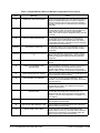
Where to Find it - Online and Printed Information:
System installation (hardware/software)............. This Manual
Agilent VIC (VXI installation software)
Module configuration and wiring........................ Module
SCPI programming.............................................. Module
SCPI example programs...................................... Module
SCPI command reference ................................... Module
Register-Based Programming ............................. Module
User’s Manual
User’s Manual
User’s Manual
User’s Manual
User’s Manual
VXIplug&play programming ............................. VXIplug&play Online Help
VXIplug&play example programs...................... VXIplug&play Online Help
VXIplug&play function reference ...................... VXIplug&play Online Help
Soft Front Panel information............................... VXIplug&play Online Help
VISA language information ................................ Agilent VISA User’s Guide
Agilent VEE programming information ............. Agilent VEE User’s Manual
*E1406-90028*
Manual Part Number: E1406-90028
Printed in Malaysia E0706
Contents
C-Size VXIbus Configuration Guide
Warranty . . . . . . . . . . . . . . . . . . . . . . . . .
WARNINGS . . . . . . . . . . . . . . . . . . . . . . .
Safety Symbols . . . . . . . . . . . . . . . . . . . . .
User Notes . . . . . . . . . . . . . . . . . . . . . . . .
Using the C-Size Configuration Guide and Agilent VIC
For More Information . . . . . . . . . . . . . . . . . .
Terms Used In This Manual . . . . . . . . . . . . . . .
.
.
.
.
.
.
.
.
.
.
.
.
.
.
.
.
.
.
.
.
.
.
.
.
.
.
.
.
.
.
.
.
.
.
.
.
.
.
.
.
.
.
.
.
.
.
.
.
.
.
.
.
.
.
.
.
.
.
.
.
.
.
.
.
.
.
.
.
.
.
.
.
.
.
.
.
.
.
.
.
.
.
.
.
.
.
.
.
.
.
.
.
.
.
.
.
.
.
.
.
.
.
.
.
.
.
.
.
.
.
.
.
.
.
.
.
.
.
.
5
6
6
7
9
10
11
Step-1 : Connect Mainframe Safety Ground (if necessary)
Grounding Procedure . . . . . . . . . . . . . . . . . . . .
Step-2 : Connect the Power Cord . . . . . . . . . . . . .
Step-3 : Where To Go Next . . . . . . . . . . . . . . . .
.
.
.
.
.
.
.
.
.
.
.
.
.
.
.
.
.
.
.
.
.
.
.
.
.
.
.
.
.
.
.
.
.
.
.
.
.
.
.
.
.
.
.
.
.
.
.
.
.
.
.
.
.
.
.
.
1-2
1-2
1-3
1-4
Setting Up the Agilent E1406A Command Module . . . . . . . . . . . . . . . .
E1406-1 : Set the Command Module as Resource Manager . . . . . . . . . .
E1406-2 : Set the Command Module as Slot 0 Device . . . . . . . . . . . . .
E1406-3 : Set the Clock Source . . . . . . . . . . . . . . . . . . . . . . . . .
E1406-4 : Set the Bus Request Level . . . . . . . . . . . . . . . . . . . . . .
E1406-5 : Configure the Command Module’s Shared RAM . . . . . . . . . .
E1406-6 : Set the Command Module’s Servant Area . . . . . . . . . . . . . .
E1406-7 : Set Command Module’s Primary GPIB Address . . . . . . . . . . .
E1406-8 : Install the Command Module into the Mainframe . . . . . . . . . .
E1406-9 : Connect Interface Cables . . . . . . . . . . . . . . . . . . . . . . .
E1406-10 : Apply Power . . . . . . . . . . . . . . . . . . . . . . . . . . . . .
Alternate Command Module Configurations . . . . . . . . . . . . . . . . . .
E1406-11 : Where To Go Next . . . . . . . . . . . . . . . . . . . . . . . . . .
Setting Up a Series 700 Controller . . . . . . . . . . . . . . . . . . . . . . . . .
System Configuration . . . . . . . . . . . . . . . . . . . . . . . . . . . . . .
Series 700-1 : Set up the Agilent E1482B VXIbus Extender Module . . . . . .
Series 700-2 : Set Up the Agilent E1406A Command Module . . . . . . . . .
Series 700-2A : Setting the Command Module Logical Address . . . . . . . .
Series 700-2B : Setting the Command Module Servant Area . . . . . . . . . .
Series 700-2C : Setting the Command Module Primary GPIB Address . . . .
Series 700-2D : Disabling the Command Module’s Slot 0 Capability . . . . .
Series 700-2E : Disabling the Command Module’s VMEbus Time Out
Capability . . . . . . . . . . . . . . . . . . . . . . . . . . . . . . . . . . . .
Series 700-3 : Install the Agilent E1482B Extender Module in the Mainframe .
Installing the E1406A Command Module . . . . . . . . . . . . . . . . . . . .
Series 700-4 : Connect the MXIbus and INTX Cables . . . . . . . . . . . . .
Series 700-5 : Apply Power . . . . . . . . . . . . . . . . . . . . . . . . . . .
Assigning Interrupt Lines . . . . . . . . . . . . . . . . . . . . . . . . . . . .
Series 700-6 : Where To Go Next . . . . . . . . . . . . . . . . . . . . . . . .
.
.
.
.
.
.
.
.
.
.
.
.
.
.
.
.
.
.
.
.
.
.
.
.
.
.
.
.
.
.
.
.
.
.
.
.
.
.
.
.
.
.
.
.
.
.
.
.
.
.
.
.
.
.
.
.
.
.
.
.
.
.
.
2-2
2-3
2-4
2-5
2-6
2-7
2-8
2-9
2-10
2-11
2-13
2-15
2-17
2-18
2-18
2-20
2-23
2-24
2-24
2-25
2-26
.
.
.
.
.
.
.
.
.
.
.
.
.
.
.
.
.
.
.
.
.
2-26
2-28
2-28
2-29
2-30
2-32
2-34
Procedure 1:
Configure the VXI Mainframe
Procedure 2:
Set Up the VXI System Controller
C-Size VXIbus Configuration Guide Contents
1
Setting Up an Embedded V743 Controller . . . . . . . . . . . . . . . . . . . . .
V743-1 : The V743 Configuration . . . . . . . . . . . . . . . . . . . . . . . .
The V743 Logical Address and Servant Area . . . . . . . . . . . . . . . . . .
V743-2 : Set Up the Agilent E1406A Command Module . . . . . . . . . . . .
V743-2A : Setting the Command Module Logical Address . . . . . . . . . . .
V743-2B : Setting the Command Module Servant Area . . . . . . . . . . . . .
V743-2C : Setting the Command Module Primary GPIB Address . . . . . . .
V743-2D : Disabling the Command Module’s Slot 0 Capability . . . . . . . .
V743-3 : Install the V743 Controller in the Mainframe . . . . . . . . . . . . .
Installing the E1406A Command Module . . . . . . . . . . . . . . . . . . . .
V743-4 : Apply Power . . . . . . . . . . . . . . . . . . . . . . . . . . . . . .
V743-4A : Enabling Shared Memory . . . . . . . . . . . . . . . . . . . . . .
V743-4B : Assigning Interrupt Lines . . . . . . . . . . . . . . . . . . . . . .
V743-5 : Where To Go Next . . . . . . . . . . . . . . . . . . . . . . . . . . .
Setting Up an Embedded Agilent RADI-EPC7 486 Computer . . . . . . . . . . .
EPC7-1 : Set the EPC7 as Slot 0 Device . . . . . . . . . . . . . . . . . . . . .
EPC7-1A : Set the EPC7 as Non-Slot 0 Device if Using Multiple Mainframes
EPC7-2 : Install the EPC7 into the Mainframe . . . . . . . . . . . . . . . . .
EPC7-3 : Install EXM Expansion Modules . . . . . . . . . . . . . . . . . . .
EPC7-4 : Configure the Command Module to Work with the EPC7 . . . . . .
EPC7-4A : Set the Command Module’s Logical Address . . . . . . . . . . . .
EPC7-4B : Set the Command Module’s Servant Area . . . . . . . . . . . . .
EPC7-4C : Set the Command Module’s Primary GPIB Address . . . . . . . .
EPC7-4D : Disable the Command Module’s slot 0 and System Controller
Capability . . . . . . . . . . . . . . . . . . . . . . . . . . . . . . . . . . . .
EPC7-5 : Connect Interface Cables . . . . . . . . . . . . . . . . . . . . . . .
EPC7-6 : Apply Power . . . . . . . . . . . . . . . . . . . . . . . . . . . . . .
EPC7-7 : Where To Go Next . . . . . . . . . . . . . . . . . . . . . . . . . . .
.
.
.
.
.
.
.
.
.
.
.
.
.
.
.
.
.
.
.
.
.
.
.
.
.
.
.
.
.
.
.
.
.
.
.
.
.
.
.
.
.
.
.
.
.
.
.
.
.
.
.
.
.
.
.
.
.
.
.
.
.
.
.
.
.
.
.
.
.
2-35
2-35
2-37
2-37
2-38
2-39
2-40
2-41
2-42
2-44
2-45
2-46
2-47
2-48
2-49
2-50
2-51
2-52
2-54
2-55
2-56
2-57
2-58
.
.
.
.
.
.
.
.
.
.
.
.
2-59
2-60
2-61
2-63
MXIbus-1 : Set Up VXI-MXI Modules for Slot 0 . . . . . . . . . . . . . . . . .
MXIbus-2 : Set VXI-MXI Modules for Non-Slot 0 . . . . . . . . . . . . . . . .
MXIbus-3 : Remove the Terminating Networks from Middle VXI-MXI Modules
MXIbus-4 : Set the VXI-MXI Module’s Logical Address . . . . . . . . . . . . .
MXIbus-5 : Disable the VMEbus Timeout on Other Modules (VME BTO) . . . .
MXIbus-6 : Install VXI-MXI Modules into Mainframes . . . . . . . . . . . . . .
MXIbus-7 : Connect Interface Cables . . . . . . . . . . . . . . . . . . . . . . . .
MXIbus-8 : Apply Power . . . . . . . . . . . . . . . . . . . . . . . . . . . . . .
MXIbus-9 : Where To Go Next . . . . . . . . . . . . . . . . . . . . . . . . . . .
.
.
.
.
.
.
.
.
.
3-4
3-5
3-9
3-10
3-20
3-22
3-24
3-25
3-25
.
.
.
.
.
.
.
.
4-3
4-4
4-8
4-11
4-14
4-15
4-16
4-17
Procedure 3:
Set Up the System for Multiple Mainframes
Procedure 4:
Configure and Install Instruments
Step-1 : Download Instrument Drivers . . . .
Step-2 : Set Instrument Logical Addresses .
Step-3 : Install A- and B-Size Modules . . .
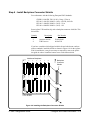
Step-4 : Install C-Size Modules . . . . . . .
Step-5 : Install a Chassis Shield . . . . . . .
Step-6 : Install Backplane Connector Shields
Step-7 : Install Faceplate Panels . . . . . . .
Step-8 : Where To Go Next . . . . . . . . .
2
C-Size VXIbus Configuration Guide Contents
.
.
.
.
.
.
.
.
.
.
.
.
.
.
.
.
.
.
.
.
.
.
.
.
.
.
.
.
.
.
.
.
.
.
.
.
.
.
.
.
.
.
.
.
.
.
.
.
.
.
.
.
.
.
.
.
.
.
.
.
.
.
.
.
.
.
.
.
.
.
.
.
.
.
.
.
.
.
.
.
.
.
.
.
.
.
.
.
.
.
.
.
.
.
.
.
.
.
.
.
.
.
.
.
.
.
.
.
.
.
.
.
.
.
.
.
.
.
.
.
.
.
.
.
.
.
.
.
.
.
.
.
.
.
.
.
.
.
.
.
.
.
.
.
.
.
.
.
.
.
.
.
.
.
.
.
.
.
.
.
Procedure 5:
Apply Power
Agilent E1406 Command Module with an External Computer
HP 9000 Series 700 Computer . . . . . . . . . . . . . . . . .
Agilent E1497A/ E1498A Embedded V743 Controller . . . .
Agilent RADI-EPC7 Embedded 486 Computer . . . . . . . .
Where To Go Next . . . . . . . . . . . . . . . . . . . . . . .
.
.
.
.
.
.
.
.
.
.
.
.
.
.
.
.
.
.
.
.
.
.
.
.
.
.
.
.
.
.
.
.
.
.
.
.
.
.
.
.
.
.
.
.
.
.
.
.
.
.
.
.
.
.
.
.
.
.
.
.
5-1
5-4
5-7
5-9
5-13
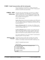
COMM1 : Verify Communication with the Instruments . . . . . . . . . . . . . . .
COMM1A : GPIB Addressing . . . . . . . . . . . . . . . . . . . . . . . . . . . . .
COMM1B : Embedded Controller Addressing . . . . . . . . . . . . . . . . . . . .
COMM1C : SICL Addressing . . . . . . . . . . . . . . . . . . . . . . . . . . . . .
COMM1D : C-SCPI Addressing . . . . . . . . . . . . . . . . . . . . . . . . . . . .
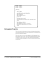
Debugging Programs . . . . . . . . . . . . . . . . . . . . . . . . . . . . . . . . . . .
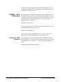
DEBUG1 : Sending SCPI Commands . . . . . . . . . . . . . . . . . . . . . . . . .
SCPI Command Structure . . . . . . . . . . . . . . . . . . . . . . . . . . . . . . .
DEBUG2 : Verify the System Logical Addresses . . . . . . . . . . . . . . . . . . .
DEBUG3 : Start Each Program by Fully Resetting Each Instrument . . . . . . . . .
DEBUG4 : Query the Instrument for Errors . . . . . . . . . . . . . . . . . . . . . .
DEBUG5 : Query all Command Parameter Settings . . . . . . . . . . . . . . . . .
DEBUG6 : Verify that the Amount of Data to be Entered is Equal to the Amount of
Data Generated . . . . . . . . . . . . . . . . . . . . . . . . . . . . . . . . . . . .
DEBUG7 : Check the Instrument’s Arm-Trigger Subsystem . . . . . . . . . . . . .
DEBUG8 : Execute Coupled Commands Within a Coupling Group . . . . . . . . .
How to Execute Coupled Commands . . . . . . . . . . . . . . . . . . . . . . . . .
DEBUG9 : Check for Command Synchronization Errors . . . . . . . . . . . . . . .
6-2
6-2
6-3
6-4
6-5
6-6
6-7
6-7
6-8
6-9
6-9
6-10
Procedure 6:
System Programming and Debugging
6-10
6-11
6-12
6-12
6-13
Appendix A:
Terms and Definitions
What is the Resource Manager? . . . . . . . . . . . . . .
What are the Slot 0 Functions? . . . . . . . . . . . . . . .
What is the Command Module’s 10 MHz Clock Source? .
What is the Command Module’s Bus Request Level? . . .
What is Command Module Memory . . . . . . . . . . . .
What is the Servant Area? . . . . . . . . . . . . . . . . .
What is the Command Module’s Primary GPIB Address?
What is the VXI-MXI Module? . . . . . . . . . . . . . .
What are the VXI-MXI Logical Address Windows . . . .
What is an Instrument Identifier? . . . . . . . . . . . . .
What are Virtual Instruments? . . . . . . . . . . . . . . .
What is the Logical Address? . . . . . . . . . . . . . . .
What are Downloadable Instrument Drivers? . . . . . . .
What Display Terminals Can Be Used? . . . . . . . . . .
What are Interrupt Lines? . . . . . . . . . . . . . . . . .
.
.
.
.
.
.
.
.
.
.
.
.
.
.
.
.
.
.
.
.
.
.
.
.
.
.
.
.
.
.
.
.
.
.
.
.
.
.
.
.
.
.
.
.
.
.
.
.
.
.
.
.
.
.
.
.
.
.
.
.
.
.
.
.
.
.
.
.
.
.
.
.
.
.
.
.
.
.
.
.
.
.
.
.
.
.
.
.
.
.
.
.
.
.
.
.
.
.
.
.
.
.
.
.
.
.
.
.
.
.
.
.
.
.
.
.
.
.
.
.
.
.
.
.
.
.
.
.
.
.
.
.
.
.
.
.
.
.
.
.
.
.
.
.
.
.
.
.
.
.
.
.
.
.
.
.
.
.
.
.
.
.
.
.
.
.
.
.
.
.
.
.
.
.
.
.
.
.
.
.
.
.
.
.
.
.
.
.
.
.
.
.
.
.
.
.
.
.
.
.
.
.
.
.
.
.
.
.
.
.
A-2
A-2
A-3
A-3
A-4
A-5
A-7
A-8
A-8
A-9
A-9
A-10
A-11
A-12
A-12
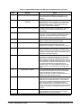
Appendix B :
Configuration and Start-up Errors
Checking for Instrument Errors . . . . . . . . . . . . . . . . . . . . . . . . . . . . B-7
C-Size VXIbus Configuration Guide Contents
3
Notes
4
C-Size VXIbus Configuration Guide Contents
Certification
Agilent Technologies certifies that this product met its published specifications at the time of shipment from the factory. Agilent
Technologies further certifies that its calibration measurements are traceable to the United States National Institute of Standards and
Technology (formerly National Bureau of Standards), to the extent allowed by that organization’s calibration facility, and to the calibration
facilities of other International Standards Organization members.
Warranty
This Agilent Technologies product is warranted against defects in materials and workmanship for a period of one (1) year from date of
shipment. Duration and conditions of warranty for this product may be superseded when the product is integrated into (becomes a part
of) other Agilent products. During the warranty period, Agilent Technologies will, at its option, either repair or replace products which
prove to be defective.
For warranty service or repair, this product must be returned to a service facility designated by Agilent Technologies. Buyer shall prepay
shipping charges to Agilent and Agilent shall pay shipping charges to return the product to Buyer. However, Buyer shall pay all shipping
charges, duties, and taxes for products returned to Agilent from another country.
Agilent warrants that its software and firmware designated by Agilent for use with a product will execute its programming instructions
when properly installed on that product. Agilent does not warrant that the operation of the product, or software, or firmware will be
uninterrupted or error free.
Limitation Of Warranty
The foregoing warranty shall not apply to defects resulting from improper or inadequate maintenance by Buyer, Buyer-supplied products
or interfacing, unauthorized modification or misuse, operation outside of the environmental specifications for the product, or improper site
preparation or maintenance.
The design and implementation of any circuit on this product is the sole responsibility of the Buyer. Agilent does not warrant the Buyer’s
circuitry or malfunctions of Agilent products that result from the Buyer’s circuitry. In addition, Agilent does not warrant any damage that
occurs as a result of the Buyer’s circuit or any defects that result from Buyer-supplied products.
NO OTHER WARRANTY IS EXPRESSED OR IMPLIED. Agilent SPECIFICALLY DISCLAIMS THE IMPLIED WARRANTIES
OF MERCHANTABILITY AND FITNESS FOR A PARTICULAR PURPOSE.
Exclusive Remedies
THE REMEDIES PROVIDED HEREIN ARE BUYER’S SOLE AND EXCLUSIVE REMEDIES. Agilent SHALL NOT BE LIABLE
FOR ANY DIRECT, INDIRECT, SPECIAL, INCIDENTAL, OR CONSEQUENTIAL DAMAGES, WHETHER BASED ON CONTRACT, TORT, OR ANY OTHER LEGAL THEORY.
Notice
The information contained in this document is subject to change without notice. Agilent Technologies MAKES NO WARRANTY OF
ANY KIND WITH REGARD TO THIS MATERIAL, INCLUDING, BUT NOT LIMITED TO, THE IMPLIED WARRANTIES OF
MERCHANTABILITY AND FITNESS FOR A PARTICULAR PURPOSE. Agilent shall not be liable for errors contained herein or for
incidental or consequential damages in connection with the furnishing, performance or use of this material. This document contains
proprietary information which is protected by copyright. All rights are reserved. No part of this document may be photocopied, reproduced,
or translated to another language without the prior written consent of Agilent Technologies, Inc. Agilent assumes no responsibility for the
use or reliability of its software on equipment that is not furnished by Agilent.
U.S. Government Restricted Rights
The Software and Documentation have been developed entirely at private expense. They are delivered and licensed as "commercial
computer software" as defined in DFARS 252.227- 7013 (Oct 1988), DFARS 252.211-7015 (May 1991) or DFARS 252.227-7014 (Jun
1995), as a "commercial item" as defined in FAR 2.101(a), or as "Restricted computer software" as defined in FAR 52.227-19 (Jun 1987)(or
any equivalent agency regulation or contract clause), whichever is applicable. You have only those rights provided for such Software and
Documentation by the applicable FAR or DFARS clause or the Agilent standard software agreement for the product involved.
Agilent C-Size VXIbus Configuration Guide
Edition 1 Rev 2
Copyright © 1998-2006 Agilent Technologies, Inc. All Rights Reserved.
Agilent C-Size VXIbus Configuration Guide
5
Printing History
The Printing History shown below lists all Editions and Updates of this manual and the printing date(s). The first printing of the manual
is Edition 1. The Edition number increments by 1 whenever the manual is revised. Updates, which are issued between Editions, contain
replacement pages to correct the current Edition of the manual. Updates are numbered sequentially starting with Update 1. When a new
Edition is created, it contains all the Update information for the previous Edition. Each new Edition or Update also includes a revised copy
of this printing history page. Many product updates or revisions do not require manual changes and, conversely, manual corrections may
be done without accompanying product changes. Therefore, do not expect a one-to-one correspondence between product updates and
manual updates.
Edition 1 (Part Number E1406-90028). . . . . . . . . . . . . . . . . . . . . . . . April 1998
Edition 1 Rev 2 (Part Number E1406-90028) . . . . . . . . . . . . . . . . . . . July 2006
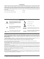
Safety Symbols
Instruction manual symbol affixed to product.
Indicates that the user must refer to the manual for specific WARNING or CAUTION
information to avoid personal injury or damage to the product.
Alternating current (AC).
Direct current (DC).
Indicates hazardous voltages.
Indicates the field wiring terminal that must
be connected to earth ground before operating
the equipment—protects against electrical
shock in case of fault.
or
Frame or chassis ground terminal—typically
connects to the equipment’s metal frame.
WARNING
CAUTION
Calls attention to a procedure, practice, or condition that could cause bodily injury or death.
Calls attention to a procedure, practice, or condition that could possibly cause damage to
equipment or permanent loss of data.
WARNINGS
The following general safety precautions must be observed during all phases of operation, service, and repair of this product.
Failure to comply with these precautions or with specific warnings elsewhere in this manual violates safety standards of design,
manufacture, and intended use of the product. Agilent Technologies assumes no liability for the customer’s failure to comply with
these requirements.
Ground the equipment: For Safety Class 1 equipment (equipment having a protective earth terminal), an uninterruptible safety earth
ground must be provided from the mains power source to the product input wiring terminals or supplied power cable.
DO NOT operate the product in an explosive atmosphere or in the presence of flammable gases or fumes.
For continued protection against fire, replace the line fuse(s) only with fuse(s) of the same voltage and current rating and type.
DO NOT use repaired fuses or short-circuited fuse holders.
Keep away from live circuits: Operating personnel must not remove equipment covers or shields. Procedures involving the removal of
covers or shields are for use by service-trained personnel only. Under certain conditions, dangerous voltages may exist even with the
equipment switched off. To avoid dangerous electrical shock, DO NOT perform procedures involving cover or shield removal unless you
are qualified to do so.
DO NOT operate damaged equipment: Whenever it is possible that the safety protection features built into this product have been
impaired, either through physical damage, excessive moisture, or any other reason, REMOVE POWER and do not use the product until
safe operation can be verified by service-trained personnel. If necessary, return the product to an Agilent Technologies Sales and Service
Office for service and repair to ensure that safety features are maintained.
DO NOT service or adjust alone: Do not attempt internal service or adjustment unless another person, capable of rendering first aid and
resuscitation, is present.
DO NOT substitute parts or modify equipment: Because of the danger of introducing additional hazards, do not install substitute parts
or perform any unauthorized modification to the product. Return the product to an Agilent Technologies Sales and Service Office for
service and repair to ensure that safety features are maintained.
6
Agilent C-Size VXIbus Configuration Guide
Notes
Agilent C-Size VXIbus Configuration Guide
7
Notes
8
Agilent C-Size VXIbus Configuration Guide
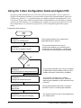
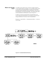
Using the C-Size Configuration Guide and Agilent VIC
Our goal is to make installation of your C-Size VXI system as easy as possible. To do so, Agilent VIC
(Agilent VXI Installation Consultant) is provided with the Agilent E1406 Command Module. Agilent VIC
is a Microsoft® Windows 3.1 program that helps you configure and install Command Module - based
VXI systems. If your system contains an Agilent E1406 Command Module to be controlled by a computer
external to the VXI mainframe, we recommend that you configure your system using Agilent VIC. For all
other configurations, or if you do not have Agilent VIC, use this configuration guide in the sequence
shown.
Configuration Guide Sequence:
Start
Here
This procedure describes how to prepare your
Agilent Mainframe for operation.
Procedure 1 :
Configure the VXI Mainframe
Procedure 2 :
Set Up the VXI System Controller
Multiple
Mainframes
?
This procedure describes how to set up
communication between your controller and the
instruments in the VXI mainframe. Configurations
for five different controller platforms are described.
NO
YES
Procedure 3 :
Set Up the System for Multiple Mainframes
Procedure 4 :
Configure and Install Instruments
9
This procedure describes how to set up your Agilent
E1482B VXIbus Extender Modules when you have
multiple mainframes communicating via MXIbus.
This procedure describes how to configure
instruments for your VXIbus system. Instrument
addressing and installation are also described in this
procedure.
Procedure 5 :
Apply Power
This procedure describes the power-on sequence
and what to look for to confirm proper installation.
Procedure 6 :
System Programming and Debugging
This procedure shows you how to start programming
your VXIbus system.
C-Size VXIbus Configuration Guide
For More Information
This manual describes how to get a C-Size VXIbus System up and running
quickly. You may require information from other manuals. The following
list describes other manuals you may need to refer to.
• To find additional information on the Agilent E1406/05 Command
Module:
Agilent E1406A Command Module User’s Manual (E1406-9000x)
• To find operating and programming information on Agilent plug-in
modules:
Refer to the manual that came with the module (E14xx-9000x or
(E13xx-9000x)
• To find information on the Standard Commands for Programmable
Instruments language (SCPI):
Beginner’s Guide to SCPI Available from Addison-Wesley
Publishing at 1-800-822-6339
• To find information on installing the Agilent E1489I MXIbus
Controller Interface Card in an HP 9000 Series 700 Computer:
Agilent E1489I MXIbus Controller Interface For HP 9000 Series
700 workstations installation Guide and Overview
• To find information on Agilent Compiled SCPI
Agilent E1570A/B E1572A Compiled SCPI for HP-UX
Agilent E1571A Compiled SCPI for MS-DOS
• To find information on the VISA Language
Agilent VISA User’s Guide
C-Size VXIbus Configuration Guide
10
Terms Used In This Manual
The following is a list of terms used in this manual. For more information
on these terms, see Appendix A, "Terms and Definitions."
Bus Request Level The bus request level is a priority at which the
Command Module can request the use of the data transfer bus.
Cardcage A cardcage is a VXIbus mainframe which allows
instruments on a card to be plugged in and operate in a VXI
environment. The Agilent E1401A Mainframe is an example of an
Agilent cardcage.
CLK10 This is the 10 MHz system clock. Clk10 is usually
provided by the system controller.
Command Module Primary GPIB Address The primary GPIB
address identifies the GPIB port.
C-SCPI Compiled SCPI is a set of C programming tools that allow
you to program register-based instruments using the high-level
SCPI language.
Data Transfer Bus The data transfer bus (DTB) is used for
addressing and data transfer.
Downloadable Device Drivers Device drivers enable
register-based modules to be programmed from the Agilent E1406
Command Module with SCPI Commands. Some drivers are
installed at the factory and other have to be installed by the user.
GPIB GPIB is Agilent Technologies’ implementation of
ANSI/IEEE Standard 488.1-1978 "IEEE Standard Digital Interface
for Programmable Instrumentation."
Instrument In this manual an instrument refers to an instrument on
a card that can be plugged into a VXI cardcage.
Logical Address The logical address is used to identify an
instrument in a VXIbus system.
Mainframe A mainframe is a VXIbus cardcage which allows
instruments on a card to be plugged in and operate in a VXI
environment. The Agilent E1401A is an example of an Agilent
mainframe.
Module A module is an instrument on a card.
11
C-Size VXIbus Configuration Guide
Resource Manager The resource manager runs at power on and
identifies all plug-in modules installed in the mainframe. The
resource manager also controls commander / servant hierarchies,
allocates interrupt lines, performs address mapping, and starts the
system operation.
SCPI SCPI stands for Standard Commands for Programmable
Instruments. It is an industry standard instrument control language
that is supported by a consortium of manufacturers.
Servant Area The servant area of a commander defines a range of
logical addresses in which all instruments within the address range
specified report to that commander.
Secondary GPIB Address The secondary GPIB address is
combined with the computer’s interface select code and Command
Modules primary GPIB address to form a module’s complete GPIB
address.
Slot 0 Device The slot 0 device locates where modules are installed
in the mainframe and manages data flow across the VXIbus
backplane. The system clock is also provided by the slot 0 device.
Virtual Instruments A virtual instrument is a combination of
several modules that are treated as a single instrument and accessed
at a single address.
VXI VXIbus is an open architecture instrument interface for
cardcage instrumentation.
VXI-MXI Module A VXI-MXI Module allows you to configure
multiple mainframes to function as a single VXIbus System.
C-Size VXIbus Configuration Guide
12
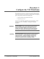
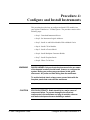
Procedure 1:
Configure the VXI Mainframe
This procedure describes how to configure the Agilent E1401B and Agilent
E1421B VXI mainframes in preparation for installing modules and applying
power. This procedure consists of the following steps:
• Connect mainframe safety ground (if necessary)
• Connect the power cord
Once you have completed the applicable steps in this procedure, continue
with the next procedure, "Procedure 2 : Set Up the VXI System
Controller."
WARNING
SHOCK HAZARD. Only service-trained personnel who are
aware of the hazards involved should install, remove, or
configure the system. Before you perform any procedures,
disconnect AC power and field wiring from the mainframe.
CAUTION
STATIC ELECTRICITY. Static electricity is a major cause of
component failure. To prevent damage to the electrical
components in the mainframe and plug-in modules, use
anti-static techniques whenever handling a module.
1-1 Configure the VXI Mainframe
C-Size Configuration Guide
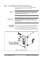
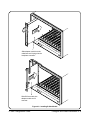
Step-1 : Connect Mainframe Safety Ground (if necessary)
When operating the Agilent 1401B or E1421B at mains frequencies
greater than 66 Hz, you must connect a safety ground.
Warning
For protection from electrical shock when operating at mains
frequencies greater than 66 Hz, connect the chassis ground
terminal to permanent earth ground.
Avertissement
Risque de Choch électrique. Si la fréquence du secteur est
supérieure à 66 Hz, relier la borne de masse du chassis à une
prise de terre fixe.
Grounding
Procedure
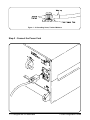
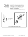
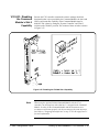
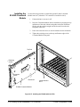
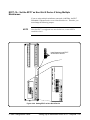
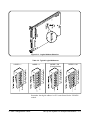
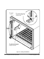
Connect a 16 AWG (1.3 mm or larger) wire to the PEM nut shown below.
The wire must be green with a yellow stripe or bare (no insulation). Use an
M4 x 10 screw, grounding lug, and toothed washers (or toothed lug) as
shown in the figure on the following page. Securely attach the other end of
the wire to a permanent earth ground using toothed washers or a toothed lug.
Figure 1 - 1. Grounding Connection
C-Size Configuration Guide
Configure the VXI Mainframe 1-2
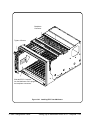
Figure 1 - 2. Grounding Screw, Toothed Washers
Step-2 : Connect the Power Cord
1-3 Configure the VXI Mainframe
C-Size Configuration Guide
Step-3 : Where To Go Next
If you have additional mainframes repeat this procedure until all
mainframes are configured. Once configured, continue with the following
procedure:
• "Procedure 2 : Set Up the VXI System Controller"
C-Size Configuration Guide
Configure the VXI Mainframe 1-4
Procedure 2:
Set Up the VXI System Controller
The controller to VXI mainframe interface determines how commands and
data will flow between the controller and the mainframe. This procedure is
divided into five sections according to the controller used:
• Setting Up the Agilent E1406A Command Module - This section
covers the setup of the Agilent E1406A Command Module
connected to an external controller using the General Purpose
Interface Bus (GPIB). See Page 2-2
• Setting Up a Series 700 Controller - This section covers the setup
of an HP 9000 Series 700 external controller with an Agilent E1489I
MXIbus Controller Interface Card connected to an Agilent E1482
VXI-MXI Bus Extender Module in slot 0. See Page 2-18
• Setting Up an Embedded V743 Controller - This section covers
the setup of an Agilent E1497A/98A Embedded V743 controller
with the VXIbus as the communication path. See Page 2-35
• Setting Up an Embedded Agilent RADI-EPC7 486 Computer -
This section covers the setup of an Agilent RADI-EPC7 Embedded
Computer with the VXIbus as the communication path.
See Page 2-49
WARNING
CAUTION
SHOCK HAZARD. Only service-trained personnel who are aware
of the hazards involved should install, remove, or configure the
system. Before you perform any procedures in this guide,
disconnect AC power and field wiring from the mainframe.
STATIC ELECTRICITY. Static electricity is a major cause of
component failure. To prevent damage to the electrical
components in the mainframe and plug-in modules, observe
anti-static techniques whenever handling a module.
2-1 Set Up the VXI System Controller
C-Size Configuration Guide
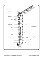
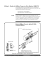
Setting Up the Agilent E1406A Command Module
This procedure explains how to set up and install an Agilent 75000 Series C
VXIbus system with an external computer (Personal Computer or
Workstation) connected to the Agilent E1406A Command Module via
GPIB. This procedure consists of the following steps:
• E1406-1 : Set the Command Module as Resource Manager
• E1406-2 : Set the Command Module as Slot 0 Device
• E1406-3 : Set the Clock Source
• E1406-4 : Set the Bus Request Level
• E1406-5 : Configure the Command Module’s Shared RAM
• E1406-6 : Set the Command Module’s Servant Area
• E1406-7 : Set the Command Module’s Primary GPIB Address
• E1406-8 : Install the Command Module into the Mainframe
• E1406-9 : Connect Interface Cables
• E1406-10 : Apply Power
• E1406-11 : Where To Go Next
If you need information on terms used in this manual, see Appendix A,
"Terms and Definitions."
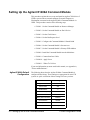
Agilent E1406A Default
Configuration
The following shows how the Agilent E1406A Command Module is
configured at the factory. These settings are appropriate for most VXI
systems. A quick verification of these settings will save you time.
Switch
Setting
Logical Address
0
Servant Area
255
GPIB Address
9
VME Bus Timer (BTO)
Enabled
Slot 0
Enabled
VME System Controller
Enabled
CLK10 Source
Internal
Bus Request Level
3
Shared RAM
Enabled (256 kB)
2-2 Setting Up the E1406 Command Module
C-Size Configuration Guide
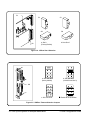
E1406-1 : Set the Command Module as Resource Manager
Set the Command Module as resource manager by setting its logical address
to 0. (The Command Module’s factory-set logical address is 0.)
Figure 2-3. Setting the Logical Address
At power-on, the resource manager function is started. The purpose of the
resource manager is to:
• identify all plug-in modules installed in the C-size mainframe
• set commander/servant hierarchies whereby one or more plug-in
modules control other plug-in modules
• perform A24/A32 address mapping so that modules requiring
additional addressing can receive it
• allocate interrupt lines to manage communication between interrupt
handler modules and interrupter modules
• start system operation
Once the power-on sequence is completed and the system is started, the
resource manager is no longer used. See Appendix A, "Terms and
Definitions," for more information on the resource manager.
C-Size Configuration Guide
Setting Up the E1406 Command Module 2-3
E1406-2 : Set the Command Module as Slot 0 Device
Set the following switches:
• Slot 0 switches to the "Enable" Position, and
• (VME) System Controller switch to the "Enable" Position.
E1406A
VME Controller
Switch Location
ENABLE = Switch Set to 0
DISABLE = Switch Set to 1
Figure 2 -4. Setting Command Module as Slot 0 Device
The slot 0 functionality is used during operation for the following purposes:
– locate where modules are installed in the mainframe
– manage (arbitrate) data flow across the VXIbus backplane busses
– provide the system clock (SYSCLK - 16 MHz)
See Appendix A, "Terms and Definitions," for additional information on the
slot 0 device.
NOTE
Once the Command Module is set as the slot 0 device, it must then be
installed in the mainframe’s slot 0.
2-4 Setting Up the E1406 Command Module
C-Size Configuration Guide
E1406-3 : Set the Clock Source
Set the clock to one of the following:
• Internal - to use the Command Module’s 10 MHz internal clock,
CLK10 (factory default), or
• External - to use the clock supplied at the SMB faceplate connector
on the Command Module.
E1406A
CLK 10 Source
Location
Figure 2-5. Setting the Clock
The clock is distributed to every slot along the VXIbus backplane.
Disabling the slot 0 and (VME) System Controller functions removes the
internal clock or external clock from the VXIbus backplane. However, the
clock from either source is still present at the ’Clk Out’ SMB connector.
See Appendix A, "Terms and Definitions," for more information about the
Command Module CLK10.
C-Size Configuration Guide
Setting Up the E1406 Command Module 2-5
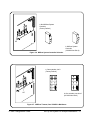
E1406-4 : Set the Bus Request Level
The Command Module’s bus request level switch is set to 3 at the factory.
In most VXIbus systems and configurations, it is not necessary to change
this setting.
E1406A
Bus Request Level 0 - 3
Bus Request Level
Location
Set the Bus Request Level by turning the dial with
a small flatblade screwdriver
Figure 2-6. Setting the Bus Request Level
The bus request level determines the priority at which the Command
Module can request the use of the Data Transfer Bus. There are four bus
request levels to choose from: 0 - 3. Bus request level 3 has the highest
priority; bus request level 0 has the lowest priority.
See Appendix A, "Terms and Definitions," for more information on the Bus
Request Level.
2-6 Setting Up the E1406 Command Module
C-Size Configuration Guide
E1406-5 : Configure the Command Module’s Shared RAM
When the E1406A expanded memory option 010 is installed, the switch
shown in Figure 2-5 is used to set one of the following configurations:
• 1 Mbyte non-volatile RAM and 256 Kbytes of shared RAM
• 2 Mbytes non-volatile RAM and 0 bytes of shared RAM
When option 010 is factory-installed, the switch is set for 1 Mbytes/
256 Kbytes. If the Command Module contains standard memory only,
setting the switch for 2 Mbytes disables the shared memory. The memory
(256 Kbytes) is not available as non-volatile memory.
See Appendix A, "Terms and Definitions," for more information on
Command Module memory allocation.
Memory Switch
Location
512K or 1M RAM,
256 Shared
2M RAM,
0 Shared
Figure 2-7. Allocating Shared RAM
C-Size Configuration Guide
Setting Up the E1406 Command Module 2-7
E1406-6 : Set the Command Module’s Servant Area
When the Command Module is the resource manager (logical address = 0),
its servant area should be set to 255. Thus, the Command Module will be
the (top level) commander for all modules with logical addresses between 1
and 255.
E1406A
SERVANT AREA = 255
OPEN = Switch Set to 0 (OFF)
CLOSED = Switch Set to 1 (ON)
Servant Area
Switch Location
Figure 2-8. Setting the Command Module’s Servant Area
In a VXIbus system, modules in the "servant area" of another module are
servants to that module (the commander). The commander module controls
servant modules by translating Standard Commands for Programmable
Instruments (SCPI) commands for register-based modules, or by serving as
the GPIB interface to message-based modules. The concept of the servant
area and commander/servant hierarchies is discussed more in Appendix A,
"Terms and Definitions."
2-8 Setting Up the E1406 Command Module
C-Size Configuration Guide
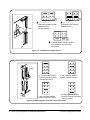
E1406-7 : Set Command Module’s Primary GPIB Address
The Command Module has a factory-set GPIB address of 9. If there is only
one Command Module (i.e. only one GPIB port) in your VXIbus
mainframe, then it is not necessary to change this setting. If there are
additional Command Modules in a system connected to the same controller
GPIB interface card, each module must have a unique primary GPIB
address. (Valid primary GPIB addresses are 0 through 30.)
See Appendix A, "Terms and Definitions," for more information on GPIB
(General Purpose Interface Bus).
GPIB ADDRESS = 9
GPIB Address
Switch Location
E1406A
OPEN = Switch Set to 0 (OFF)
CLOSED = Switch Set to 1 (ON)
Figure 2- 9. Setting the Primary GPIB Address
"GPIB Controller" switch - ’1’ sets the Command Module as the GPIB
system controller (IBASIC applications) and ’0’ sets the talk/listen mode.
This switch should be set to ’1’ when IBASIC, rather than an external
controller, is to be the system controller.
"Diagnostic" switch - ’1’ allows the resource manager to start the system
instrument but does not start any installed devices. ’0’ starts the entire
system.
"VME BTO Disable" switch - ’1’ disables the Command Module from
functioning as the Data Transfer Bus timer. This function must only be
disabled when VXI-MXI mainframe extender modules are part of your
VXIbus system.
C-Size Configuration Guide
Setting Up the E1406 Command Module 2-9
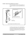
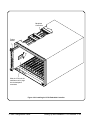
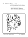
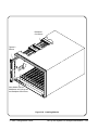
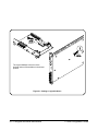
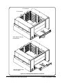
E1406-8 : Install the Command Module into the Mainframe
Use the following procedure to install the Agilent E1406A Command
Module into slot 0.
1.
Turn off power on the mainframe by pressing the power button in
the lower left corner.
2.
If the modules will be installed into a D-Size mainframe, install a
support designed for installing C-Size cards in D-Size mainframes.
3.
Insert the module into the mainframe by aligning the top and bottom
of the card with the card guides inside the mainframe. Slowly push
the module straight into the slot until it touches the backplane
connectors.
4.
Push in the extraction levers to seat the module into the mainframe.
5.
Tighten the retaining screws on the top and bottom edges of the
front panel.
Backplane
Connectors
Tighten 2
Screws
Extraction
Levers
Slide Module into the
Mainframe until it touches
the Backplane Connectors
Figure 2-10. Installing Modules
2-10 Setting Up the E1406 Command Module
C-Size Configuration Guide
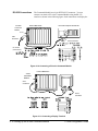
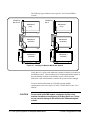
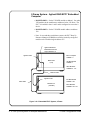
E1406-9 : Connect Interface Cables
NOTE
Refer to your controller’s documentation for information on connecting the
keyboard and video cables and other peripherals.
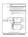
GPIB Connections
Connect one end of the GPIB Cable to your external computer (PC or
Workstation) and the other end to the Agilent E1406A Command Module
installed in the Mainframe.
You can also connect a terminal or PC to the Command Module using the
RS-232 interface as shown. Such a connection will display the Command
Module’s power-on and configuration sequence, and function as a front
panel to your VXIbus C-Size system.
Computer
E1406A
E1401A Mainframe
Terminal
GPIB
RS-232
Figure 2-11. Typical GPIB Connections
C-Size Configuration Guide
Setting Up the E1406 Command Module 2-11
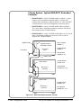
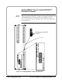
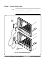
RS-232 Connections
The Command Module has a 9-pin DTE RS-232 connector. You can
connect a terminal or PC to the Command Module using the RS-232
interface as shown in the following figure. Such connections can display the
E1401A Mainframe
E1406A
Command
Module
Personal Computer with RS-232
9 Pin
Connector
9 Pin Connector
HP 24542U
(24540-80014)
Figure 2-10. Connecting a PC to the Command Module
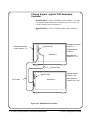
E1401A Mainframe
E1406A
Command
Module
9 Pin
Connector
25 Pin
Connector
Figure 2-11. Connecting a Display Terminal
2-12 Setting Up the E1406 Command Module
C-Size Configuration Guide
Command Module’s power-on and configuration sequence, and function as
a front panel to your VXIbus C-Size system.
See Appendix A, "Terms and Definitions," for information on the
Command Module’s RS-232 interface configuration
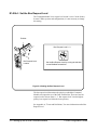
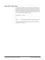
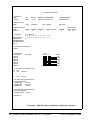
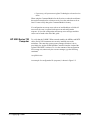
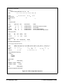
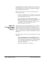
E1406-10 : Apply Power
Check that the Agilent E1406A Flash ROMS switch is in the "Run"
position and then turn on the VXI mainframe. An example of the E1406A’s
power-on and configuration sequence is shown in Figure 2-12. This
sequence can be monitored on an RS-232 terminal or printer connected to
the Command Module’s RS-232 serial interface port (see "RS-232
Connections" on page 2- 12). Pressing CTRL S on the terminal keyboard
pauses the sequence. Pressing CTRL Q allows the sequence to resume. Note
that once the sequence is paused, it remains paused until CTRL Q is
pressed.
NOTE
Configuration and
Start-Up Errors
If a serial terminal or printer is not available, the program in Procedure 6
can be used to check your system.
If the Command Module fails its self test, the "Failed" annunciator lights up
on the faceplate. Should this occur:
• turn the mainframe off, remove the Command Module, check the
configuration switches (i.e. logical address, slot 0/system controller
enable).
• if necessary, call your nearest Agilent Technologies sales and service
office.
NOTE
When using the Command Module for the first time or when the mainframe
has not been turned on for at least one week, leave the mainframe on for at
least 15 hours to fully charge the Command Module’s battery.
If a configuration or start-up error such as an invalid address or failed self
test occurs, the error is reported in the power-on and configuration
sequence. A list of the configuration and start-up error messages and their
causes can be found at the end of this guide.
C-Size Configuration Guide
Setting Up the E1406 Command Module 2-13
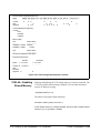
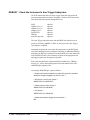
1.
2
3
4
5.
6.
Testing ROM
Testing 512K Bytes RAM
Passed
Testing CPU
CPU Self Test Passed
GPIB address: 09
Talk/Listen
Command Module ladd = 0
Command Module servant area = 255
Command Module VME bus timeout -- DISABLED
Searching for static devices in mainframe 0
SC device at ladd
0 in slot 0
Searching for static devices on interconnect bus 1
Searching for dynamic devices in mainframe 0
Searching for pseudo devices
Configuring Commander / Servant hierarchy
ladd = 0, cmdr ladd = -1
Validating Commander / Servant hierarchy
Mapping A24 Memory
ladd 0, offset = 00200000H, size = 131072 Bytes
Mapping A32 memory
Configuring VME interrupts
VME interrupt line 1 assigned to ladd 0, handler ID 1
VME interrupt line 2 - no handler assigned
VME interrupt line 3 - no handler assigned
VME interrupt line 4 - no handler assigned
VME interrupt line 5 - no handler assigned
VME interrupt line 6 - no handler assigned
VME interrupt line 7 - no handler assigned
SYSTEM INSTALLED AT SECONDARY ADDR 0
SYSTEM instrument started
File System memory: 40131
File System Started
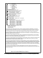
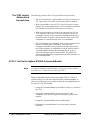
1. The Agilent E1406A operating system performs a series of self-tests and clears its volatile RAM. The Command
Module’s GPIB address, logical address, servant area, and VME (data transfer) bus timer functionality are reported. You
must disable the VME bus timer when Agilent E1482A VXI-MXI mainframe extender modules are part of your system.
2. For each mainframe, the resource manager locates all statically configured modules, locates and configures all
dynamically configurable modules, and then locates pseudo devices such as IBASIC. The VXI-MXI extender outward and
inward logical address windows are then opened.
3. The resource manager establishes the VXIbus system’s commander/servant hierarchies based on the commander’s
servant area and the servant’s logical address. The Command Module in this configuration is the top-level commander,
and as such, is not a servant to another commander (cmdr ladd = -1).
4. The resource manager allocates A24 and A32 addresses for those modules’ memory requirements. Note that the offset
is specified in hexadecimal and the size is specified in bytes. A24 and A32 address space is opened up to modules
accessed through the VXI-MXI mainframe extender modules.
5. The resource manager allocates interrupt lines to all interrupt handlers in the system. Agilent register-based modules
have their interrupt line jumper set to ’1’ at the factory. In systems with multiple Command Modules the other interrupt lines
are assigned. Modules controlled by those Command Modules must have their jumpers moved accordingly. Interrupt line
’1’ is enabled to route interrupts OUT from mainframe 137 to the handler in mainframe 0. Interrupt line ’1’ is enabled to
route interrupts IN to the interrupt handler in mainframe 0 (VXIbus extender 2). All other interrupt routing lines are disabled
since there are no other interrupt handlers.
6. The resource manager identifies the secondary GPIB addresses in the system, starts the system instrument (i.e.
Command Module), issues the Begin Normal Operation (BNO) command to its message based servants and opens GPIB
access to those modules.
Figure 2-12. The Agilent E1406A Power-on Sequence
2-14 Setting Up the E1406 Command Module
C-Size Configuration Guide
Alternate
Command Module
Configurations
Resource Manager
Only
Slot 0 Only
Multiple Command
Modules
C-Size Configuration Guide
The procedures in this chapter have described how to configure the
Agilent E1406A Command Module as the system’s resource manager and
slot 0 device. There may be times when you do not need a Command
Module configured for these functions. The following sections describe
such situations.
If the Command Module is to function only as the resource manager and not
as the slot 0 device (note that dynamic configuration and slot identification
will not be done):
1.
Set the Command Module’s logical address to 0.
2.
Set the Slot 0 and System Controller switches to "Disable".
3.
Install the Command Module in a slot other than slot 0.
4.
Configure another device to provide the system’s slot 0 functions.
If the Command Module is to function only as the slot 0 device and not as
the resource manager:
1.
Set the Command Module’s logical address to a value other than 0.
2.
Set the Slot 0 and System Controller switches to "Enable".
3.
Set the CLK10 source to "Internal".
4.
Install the Command Module in slot 0.
5.
Configure another device to perform the resource manager function.
In systems where there are several Command Modules:
1.
Configure one Command Module as the resource manager and
slot 0 device as described earlier in this procedure.
2.
Set the logical addresses and servant areas of the additional
Command Modules based on the logical addresses of their servant
modules.
3.
Each Command Module must have a unique primary GPIB address
if it is connected to the same controller GPIB interface card.
4.
Disable the Slot 0 and (VME) System Controller functions on each
Command Module not functioning as the resource manager or slot 0
device; there can be only one resource manager and slot 0 device in
a system.
Setting Up the E1406 Command Module 2-15
5.
Only one Command Module is required to translate SCPI
commands for the system’s Agilent register-based modules provided the register-based modules are in the Command Module’s
servant area, they are assigned secondary addresses, and the
Command Module contains the instrument drivers.
6.
When a Command Module is in the servant area of another
Command Module, the Command Module functioning as the
resource manager will report one of the following error conditions:
Error 11: INVALID INSTRUMENT ADDRESS
3, Config warning, Device driver not found
Error 11 occurs when the Command Module’s logical address is not
a multiple of 8. The configuration warning occurs when the logical
address is a multiple of 8. In either case, the error or warning can be
ignored.
7.
Communication and timing between a Command Module and its
servants is achieved using VXIbus backplane interrupt lines. The
interrupt lines are assigned at power-on by the resource manager.
The Command Module resource manager assigns interrupt line 1 to
itself. The other interrupt lines are assigned to the system’s
programmable handlers. Unused interrupt lines are not assigned.
Agilent’s register-based modules are factory-set to interrupt line 1.
Thus, for those modules which are servants to a Command Module
assigned an interrupt line other than 1, the jumper must be moved to
match their Command Module. Refer to the module’s
documentation for the jumper location. The Command Module
resource manager configuration sequence earlier in this procedure
shows the interrupt line assigned.
2-16 Setting Up the E1406 Command Module
C-Size Configuration Guide
E1406-11 : Where To Go Next
So far you should have done the following:
• Configured your Agilent E1406A Command Module for operation
with an external computer (PC or Workstation)
• Installed the Command Module into the Mainframe
• Connected Interface Cables
• Applied Power and verified operation
Once you are done with this procedure, continue with one of the following
procedures:
If you have multiple mainframes connected via MXIbus:
• "Procedure 3: Set Up Your System for Multiple Mainframes"
If you are using one mainframe:
• "Procedure 4: Configure and Install Instruments"
C-Size Configuration Guide
Setting Up the E1406 Command Module 2-17
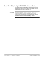
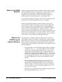
Setting Up a Series 700 Controller
This procedure describes the system configuration and steps necessary for
an HP 9000 Series 700 controller to be used as a VXI instrument controller.
The steps in this procedure include:
• Series 700-1 : Set Up the Agilent E1482B VXIbus Extender Module
• Series 700-2 : Set Up the Agilent E1406A Command Module
• Series 700-3 : Install the Agilent E1482B Extender Module in the
Mainframe
• Series 700-4 : Connect the MXIbus and INTX Cables
• Series 700-5 : Apply Power
• Series 700-6 : Where To Go Next
System
Configuration
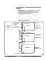
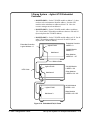
As shown in Figure 2-13, the HP 9000 Series 700 computer interfaces to the
VXI mainframe through the Agilent E1489I MXIbus controller interface
card and a Agilent E1482B VXIbus Extender (VXI-MXI) Module installed
in mainframe slot 0. The Agilent E1489I requires the Agilent E2093B SICL
software. The E1489I and the SICL software provide the system’s resource
manager functionality. The Agilent E1482B module performs the system’s
slot 0 functions.
When using a Series 700 controller, communication between the computer
and the instruments in the mainframe is through the SICL language or
Compiled SCPI (C-SCPI).
Note
This procedure covers configuration of the Agilent E1482B VXIbus
Extender Module for use with the Series 700 controller. The procedure
assumes the Agilent E1489I MXIbus controller interface card and the
Agilent E2093B SICL software are already installed in the Series 700
controller. The following manuals contain installation information on the
card and software:
Agilent E1489I MXIbus Controller Interface for HP 9000 Series 700
Workstations "Installation Guide and Overview" (E1489-90000)
"SICL Installation Guide" (E2090-90003)
2-18 Setting Up a Series 700 Computer
C-Size Configuration Guide
HP 9000 Series 700 Controller w/
Agilent E1489I MXIbus Controller
Interface
MXI and INTX Cables
(Agilent E1482B Opt.
001 or Opt. 004)
INTX
MXI
C-Size VXI Mainframe
Agilent E1482B VXIbus
Figure 2-13. VXIbus System with a Series 700 Computer
C-Size Configuration Guide
Setting Up a Series 700 Computer 2-19
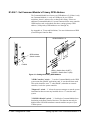
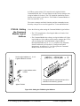
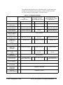
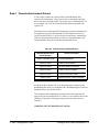
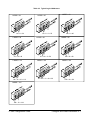
Series 700-1 : Set up the Agilent E1482B VXIbus Extender Module
The Agilent E1482B VXI-MXI module is factory configured for use in
mainframe slot 0. Table 2-1 lists the factory (slot 0) settings. Verify the
module settings against Table 2-1 and Figure 2-14.
CAUTION
STATIC ELECTRICITY. Static electricity is a major cause of
component failure. To prevent damage to the electrical
components in the mainframe and plug-in modules, observe
anti-static techniques whenever handling a module.
2-20 Setting Up a Series 700 Computer
C-Size Configuration Guide
Table 2-1. E1482B Slot 0 and Non Slot 0 Configurations
Setting
Switch/
Jumper
Trigger Input
Termination
S5
Trigger 50Ω terminated
Ext Clk SMB
S6
Output external clock
MXIbus Terminating
Resistor Networks
---
Remove unless last device
in daisy chain
Installed
MXI Controller
Timeout Level
W8
MXIbus timeout disabled
MXIbus timeout =100 µs
VME BTO Level
W6
VMEbus timeout = 100 µs
VMEbus timeout = 200 µs
INTX Terminating
Resistor Networks
---
Remove unless last device
in daisy chain
Installed
MXIbus Fairness
S2
Fairness enabled
Interlocked Arbitration
S3
Interlocked
MXI System Controller
S4
Not MXIbus controller
MXIbus controller
Logical Address
---
Set the logical address to
1, 2, or 3
Set the logical address to
the number above a
window boundary (e.g.
boundary = 128, logical
address = 129)
VXIbus Slot 0 Device
S1, S8
Slot 0
Non-Slot 0
Front Panel
Pushbutton
S7
VME BTO Chain
Position
W7
VMEbus Request Level W1 - W5
CLK10 Source
CLK10 Mapping
C-Size Configuration Guide
Agilent E1482B VXI-MXI
Extender Module
Slot 0
(factory settings)
SYSRESET* asserted
1 extender, slot 0
1 extender, non-slot 0
Level 3 requester
W9, W10 On-board 10 MHz VXI-MXI
installed in slot 0
W1 - W3
Agilent E1482B VXI-MXI
Extender Module
Non Slot 0
Do not source CLK10
CLK10 mapping disabled
Setting Up a Series 700 Computer 2-21
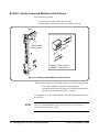
Figure 2-14. E1482B VXI-MXI Extender Slot 0 Configuration
Note
If an Agilent E1406A Command Module is part of your system, continue
with step Series 700-2. Otherwise proceed to step Series 700-3.
2-22 Setting Up a Series 700 Computer
C-Size Configuration Guide
Series 700-2 : Set Up the Agilent E1406A Command Module
If an Agilent E1406A Command Module is part of your Series 700/MXI
based VXIbus system, you must configure the Command Module for use
with the Series 700 computer and the Agilent E1482B VXIbus Extender
module. This includes:
• setting the Command Module logical address so that it is a servant to
the Series 700
• setting the Command Module servant area so that it is the
commander of the system’s Agilent Technologies register-based
modules
• setting the Command Module primary GPIB address
• disabling the Command Module’s slot 0 and system controller
capability
• disabling the Command Module’s VMEbus Time Out capability
In VXIbus systems with an HP Series 700 computer, Agilent E1482B
MXIbus Extender, and a Agilent E1406A Command Module, the
following configuration is recommended:
– Series 700 (with the Agilent E1489I MXIbus Controller
Interface) is the resource manager
– Agilent E1482B MXIbus Extender is the slot 0 device
– Agilent E1406A Command Module is the commander to the
system’s Agilent Technologies register-based modules
The resource manager and slot 0 functions and commander/servant
hierarchy concepts are covered in Appendix A "Terms and Definitions".
C-Size Configuration Guide
Setting Up a Series 700 Computer 2-23
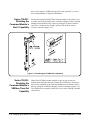
Series 700-2A :
Setting the
Command Module
Logical Address
Notice the following when setting the Command Module logical address.
• The Command Module has a factory-set logical address of 0. Since
logical address 0 is the address of the resource manager (the Agilent
E1489I card in the Series 700), you must change the Command
Module’s logical address. Recommended addresses are 1, 2, or 3.
Set the logical address to 1, 2, or 3.
Logical address 0 is shown.
Logical address switch
The logical address is the decimal sum of the
switches in the closed (1) position.
Agilent E1406A
Figure 2-15. Setting the E1406A Logical Address
Series 700-2B :
Setting the
Command Module
Servant Area
Notice the following when setting the Command Module servant area.
• For the Command Module to be the commander of a register-based
module, the register-based module’s logical address must fall within
the Command Module’s servant area. The servant area of the
Command Module is determined as:
Servant area = (logical address + 1) through (logical address +
servant area switch setting)
• The logical address plus the Command Module’s servant area cannot
exceed 255. Therefore, set the servant area based on the logical
addresses of the register-based modules in your system.
For example, if the Command Module’s logical address is 1 and its
servant area switch is set to 100, the Command Module would be the
commander for all modules with logical addresses from 2 through
101.
2-24 Setting Up a Series 700 Computer
C-Size Configuration Guide
E1406A
Servant area switch
location
The servant area is the decimal sum of the switches in the
closed (1) position
Figure 2-16. Setting the E1406A Servant Area
Series 700-2C :
Setting the
Command Module
Primary GPIB
Address
Register-based modules in the servant area of the Command Module are
accessed from the Series 700 computer across GPIB and through the
Agilent E1406A Command Module. The primary GPIB address identifies
the GPIB port on the Command Module. This address is combined with the
Command Module’s secondary GPIB address (always 00), and with the
Primary GPIB
address switch
location
E1406A
Figure 2-17. Setting the E1406A Primary HP-IB Address
C-Size Configuration Guide
Setting Up a Series 700 Computer 2-25
Series 700 computer’s (GPIB) interface select code (typically 7), to form
the Command Module’s complete GPIB address.
Series 700-2D :
Disabling the
Command Module’s
Slot 0 Capability
Because the Agilent E1482B VXIbus Extender module is the system’s slot
0 module, the slot 0 and VME system controller capability of the Command
Module must be disabled. This is done by setting the "System Controller"
and "Slot 0" switches to the "Disable" position. The location of these
switches is shown in Figure 2-18.
Figure 2-18. Disabling the E1406A Slot 0 Capability
Series 700-2E :
Disabling the
Command Module’s
VMEbus Time Out
Capability
When E1482 VXIbus Extender modules are part of your system, the
modules must function as the Data Transfer Bus (DTB) timer. This means
the bus timer capability of the Command Module must be disabled. This is
done by setting the ’VME BTO Disable’ switch as indicated in Figure 2-19.
The VMEbus timer capability (VME BTO Level) of the E1482B is enabled
at the factory.
2-26 Setting Up a Series 700 Computer
C-Size Configuration Guide
Agilent E1406A
switch location
Figure 2-19. Disabling the E1406A VMEbus Time OutCapability
Note
C-Size Configuration Guide
When using the Agilent E1406A Command Module with the HP Series 700
computer, an interrupt line other than line 1 is assigned to the Command
Module. In order for the Command Module and the instruments in its
servant area to function properly, the devices must use the same interrupt
line. Refer to "Assigning Interrupt Lines" in step Series 700-5: "Apply
Power" for more information.
Setting Up a Series 700 Computer 2-27
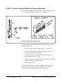
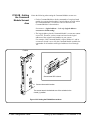
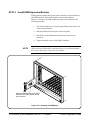
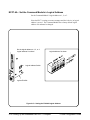
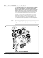
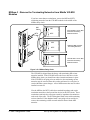
Series 700-3 : Install the Agilent E1482B Extender Module in the
Mainframe
Use the following procedure to install the Agilent E1482B VXIbus
Extender Module into mainframe slot 0.
Installing the
E1406A Command
Module
1.
If the mainframe is on, turn it off.
2.
Insert the module into the mainframe by aligning the top and
bottom of the VXIbus extender module with the card guides inside
the mainframe. Slowly push the module into slot 0 until it seats in
the backplane connector.
3.
Tighten the retaining screws on the top and bottom edges of the
module’s front panel.
Use the following procedure to install the Agilent E1406A Command
Module into slot 1 (when the Agilent E1482B module is installed in slot 0).
1.
If the mainframe is on, turn it off.
2.
Insert the Command Module into the mainframe by aligning the top
and bottom of the card with the card guides inside the mainframe.
Slowly push the module straight into the slot until it seats in the
backplane connectors. The front panel of the module should be
even with the front panel of the mainframe.
3.
Tighten the retaining screws on the top and bottom edges of the
Command Module front panel.
2-28 Setting Up a Series 700 Computer
C-Size Configuration Guide
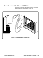
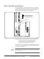
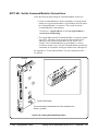
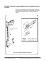
Series 700-4 : Connect the MXIbus and INTX Cables
The MXI and INTX cables are connected between the Series 700 controller
and the E1482B extender module as shown in Figure 2-20.
Figure 2-20. Connecting the MXIbus and INTX Cables
C-Size Configuration Guide
Setting Up a Series 700 Computer 2-29
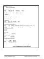
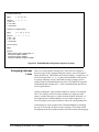
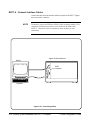
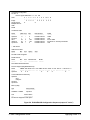
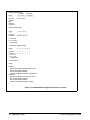
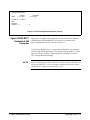
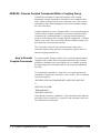
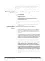
Series 700-5 : Apply Power
To verify that the E1482B VXIbus extender module and the MXIbus and
INTX cables are correctly installed, turn on the mainframe. This starts the
system resource manager function (ivxirm) provided by the Agilent E1489I
MXIbus Controller Interface card and the Agilent E2093B SICL software.
To view the contents of the configuration file (rsrcmgr.out) written to by the
resource manager, type the following command:
/usr/pil/bin/ivxisc
(HP-UX)
or
IVXISC
(from the directory the resource manager executes from)
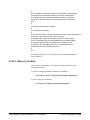
An example of the configuration file (sequence) with only the E1482B
installed is shown in Figure 2-21.
2-30 Setting Up a Series 700 Computer
C-Size Configuration Guide
VXI Current Configuration:
MXI BUS: 0
Device Logical Addresses: 0 1
VXI Device Table:
Name
--------hpmxictlr
hpvximxi
LADD Slot
-------- -----0
*
1
*
Bus
-----0
0
Manufacturer
-------------------Agilent Technologies
Agilent Technologies
Space
---------
Size
------
Model
---------0x8fd
0xfe
* - MXI device
VME Device Table:
Name
Bus Slot
---------------No VME cards configured.
Failed Devices:
Name
Bus Slot Manufacturer
Model
------------------------------------- ---------No FAILED devices detected.
Protocol Support (Msg Based Devices):
Name
-------hpmxictlr
CMDR SIG MSTR INT FHS SMP RG EG ERR PI PH TRG I4 I LW ELW 1.3
--------- ----- --------- ----- ----- ------ ---- ---- ------ --- ---- ------ -- -- --- ----- ---X
X X
X
X
X
X
Commander/Servant Hierarchy:
hpmxictlr
hpvximxi
Memory Map;
A24
----0x200000 - 0x2ffffff
Device Name
-------------------hpmxictlr
A32
Device Name
-----------------------No devices mapped into A32 space.
Interrupt Request Lines:
Handler
Interrupter
Name
1234567 1234567
--------------------------------------------hpmxictlr
X XX X X X X
hpvximxi
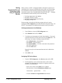
Figure 2-21. E1489I/E2093B Configuration Sequence
C-Size Configuration Guide
Setting Up a Series 700 Computer 2-31
VXI-MXI IRQ Routing:
Name
1 2 3 4 5 6 7
-------- - - - - - hpvximxi
I I I I I I I
I - MXI->VXI
O - VXI->MXI
* - Not Routed
VXI-MXI TTL Trigger Routing:
Name
0 1 2 3 4 5 6 7
--------- - - - - - - hpvximxi
I I I I I I I I
I - MXI -> VXI
O - VXI -> MXI
* - Not Routed
VXI-MXI Registers:
Name
-------hpvximxi
laddr window register: 0x3f00 range: 0-1
a24 window register: disabled
a32 window register: disabled
Interrupt Configuration Register: 0xffffffff
Figure 2-21. E1489I/E2093B Configuration Sequence (Cont’d)
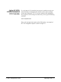
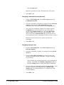
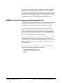
Assigning Interrupt
Lines
There are seven backplane interrupt lines. These lines are assigned to
devices by the resource manager during the system’s power-on sequence.
When the HP Series 700/E1489I is the resource manager, it assigns line 1 to
itself, and assigns lines 2, 3, 4, ... to other interrupt handlers in the system.
In systems containing a Series 700/E1489I (resource manager) and an
Agilent E1406A Command Module, the Series 700/E1489I will assign the
Command Module interrupt line 2 - if the Command Module has the next
lowest logical address.
Agilent Technologies’ register-based modules are factory-set to interrupt
line 1. This setting is selected on some modules by a finger-moveable
jumper; on others the jumper is soldered onto the module. When line 1 is
not assigned to the Command Module, you must either assign line 1, or
move the jumpers on its register-based servants to the corresponding lines.
An Interrupt line can be assigned to the Command Module by modifying
the "irq.cf" file used by the Series resource manager. The location of this
file depends on the Series platform shown in the table on the following page.
2-32 Setting Up a Series 700 Computer
C-Size Configuration Guide
Platform
Location of file "irq.cf"
HP-UX
/usr/pil/etc/vxi16/irq.cf
BASIC/WS
must be in the directory the resource
manager executes from.
As an example, to assign interrupt line 1 to the Command Module:
1. Modify "irq" by adding the line shown in bold. The file listed below is
the HP-UX version of "irq.cf".
2. Re-save the file and re-run the resource manager program. Re-run
program "ivxisc" (or "IVXISC") and verify that the interrupt line has been
assigned.The section "Interrupt Request Lines" in Figure 2-40 will show if
the line has been assigned.
#
# This database contains the mapping of VXI devices to Interrupt lines.
# Note that not all VXI devices need to use interrupt lines and that
# not all interrupt lines need to be assigned. However, no interrupt
# line that is allocated in this file can be allocated in the ’vmedevices’
# file.
#
# The format of this files is as follows:
#
# line handler interruptors ...
#
# All fields are <tab> or <space> seperated. All values can be expressed in
# decimal, or hex. The ’line’ field is the interrupt line
# being allocated. There can be at most one line for each interrupt
# line. The handler field is the logical address of the interrupt handler
# for this line (not that only one handler can be assigned for any
# given line). The interruptors field is a list of logical addresses of
# interrupters that can use this interrupt line.
#
1 2
As shown, interrupt line 1 will be assigned to the Command Module at
logical address 2.
C-Size Configuration Guide
Setting Up a Series 700 Computer 2-33
Series 700-6 : Where To Go Next
Once you have installed the Agilent E1482 VXIbus extender module,
continue with one of the following procedures:
If you have multiple mainframes connected via MXIbus:
• "Procedure 3: Set Up Your System for Multiple Mainframes"
If you are using one mainframe:
• "Procedure 4: Configure and Install Instruments"
2-34 Setting Up a Series 700 Computer
C-Size Configuration Guide
Setting Up an Embedded V743 Controller
This procedure describes the system configuration and steps necessary for
an Agilent E1497A V743/64 or Agilent E1498A V743/100 Embedded
Controller to be used as a VXI instrument controller. The steps in this
procedure include:
• V743-1 : The V743 VXI Configuration
• V743-2 : Set Up the Agilent E1406A Command Module
• V743-3 : Install the V743 Controller in the Mainframe
• V743-4 : Apply Power
• V743-5 : Where To Go Next
V743-1 : The V743 Configuration
As shown in Figure 2-31, the V743 controller requires the following
software package:
Agilent E2091C - Standard Instrument Control Library (SICL) HP-UX 9.05
(version C.03.02)
The V743 with the Agilent E2091C software provides the system’s resource
manager functionality. The V743 also provides the system’s slot 0 functions
when the controller is installed in mainframe slot 0.
Communication between the V743 controller and the instruments in the
mainframe is across the VXIbus backplane, or across GPIB through the
Agilent E1406A Command Module.
Note
C-Size Configuration Guide
This procedure lists the V743 VXI configuration and covers installation of
the controller into a VXI mainframe. The procedure does not cover
installation of the Agilent E2091C software. Refer to the software
documentation for software installation information.
Setting Up an Embedded V743 Controller 2-35
The Agilent V743/64 and
V743/100 Embedded
Controllers require the
Agilent E2091C SICL software
Reset Switch
LEDs
Clock I/O
Trigger I/O
Speaker Out
RAM connectors
inside
GPIB
Digital Video
SCSI
LAN
Video
RS-232 (B)
Mouse
RS-232 (A)
Keyboard
Figure 2-31. The V743 Embedded Controller
2-36 Setting Up an Embedded V743 Controller
C-Size Configuration Guide
The V743 Logical
Address and
Servant Area
The following pertains to the V743 logical address and servant area:
• The V743 controller has a logical address of 0 and a servant area of
255. These values are stored in software and cannot be changed.
• With a logical address of 0, the V743 is the VXI system’s resource
manager. It is recommended that the V743 be installed in mainframe
slot 0 so that it also functions as the system’s slot 0 device.
• With its logical address set at 0 and its servant area set at 255, the
V743 controller is the system’s top level commander. However, a
commander can be a servant to another commander thus forming a
hierarchial system. Servants in the servant area of the "lower-level"
commander are controlled by the lower-level commander.
• The V743 should be the commander of the system’s message-based
modules (including other commanders). This enables the
message-based modules to be programmed at higher speeds across
the VXIbus backplane. A commander such as the Agilent E1406A
Command Module should be the commander for the system’s
Agilent Technologies register-based modules. This enables the
register-based modules to be programmed with SCPI commands via
the Command Module.
V743-2 : Set Up the Agilent E1406A Command Module
Note
If an Agilent E1406A Command Module is part of your system, continue
with Step V743-2. Otherwise, proceed to step V743-3.
When an embedded controller such as the Agilent E1497A V743/64 or
Agilent E1498A V743/100 and a Agilent E1406A Command Module are
part of your VXIbus system, you must configure the Command Module for
use with the V743. This includes:
• setting the Command Module logical address so that it is a servant to
the V743
• setting the Command Module servant area so that it is the
commander of the system’s Agilent Technologies register-based
modules
• setting the Command Module primary GPIB address
• disabling the Command Module’s slot 0 and system controller
capability
C-Size Configuration Guide
Setting Up an Embedded V743 Controller 2-37
In VXIbus systems with a V743 controller and a Agilent E1406A
Command Module, the V743 must function as the resource manager since
its logical address is fixed at 0. The V743 should be installed in slot 0 to
function as the system’s slot 0 device. The E1406A Command Module is
then a servant of the V743.
The resource manager and slot 0 functions, and the commander/servant
hierarchy concepts are covered in Appendix A "Terms and Definitions".
V743-2A : Setting
the Command
Module Logical
Address
Notice the following when setting the Command Module logical address.
• The V743 controller has a fixed logical address of 0 and a fixed
servant area of 255.
• The Command Module has a factory-set logical address of 0. Since
logical address 0 is the address of the resource manager (the V743),
you must change the Command Module’s logical address.
Recommended addresses are 1, 2, or 3, which are not instrument
identifier addresses (see Procedure 4: Configure and Install
Instruments). An address of 1, 2, or 3 also places the Command
Module in the servant area of the V743.
Set the logical address to 1, 2, or 3.
Logical address 0 is shown.
Logical address switch
location
The logical address is the decimal sum of the
switches in the closed (1) position.
Agilent E1406A
Figure 2-32. Setting the E1406A Logical Address
2-38 Setting Up an Embedded V743 Controller
C-Size Configuration Guide
V743-2B : Setting
the Command
Module Servant
Area
Notice the following when setting the Command Module servant area.
• For the Command Module to be the commander of a register-based
module, the register-based module’s logical address must fall within
the Command Module’s servant area. The servant area of the
Command Module is determined as:
Servant area = (logical address + 1) through (logical address +
servant area switch setting)
• The logical address plus the Command Module’s servant area cannot
exceed 255. Therefore, set the servant area based on the logical
addresses of the register-based modules in your system.
For example, if the Command Module’s logical address is 1 and its
servant area switch is set to 100, the Command Module would be the
commander for all modules with logical addresses from 2 through
101.
E1406A
Servant area 255 is shown.
Servant Area switch location
The servant area is the decimal sum of the switches in the
closed (1) position.
Figure 2-33. Setting the E1406A Servant Area
C-Size Configuration Guide
Setting Up an Embedded V743 Controller 2-39
V743-2C : Setting
the Command
Module Primary
GPIB Address
Register-based modules in the servant area of the Command Module are
accessed from the V743 across GPIB and through the Agilent E1406A
Command Module. The primary GPIB address identifies the GPIB port on
the Command Module. This address is combined with the Command
Module’s secondary GPIB address (always 00), and with the V743
controller’s (GPIB) interface select code (typically 7), to form the
Command Module’s complete GPIB address.
The location of the primary GPIB address switch is shown in Figure 2-34.
Primary GPIB Address
Switch location
E1406A
Figure 2-34. Setting the E1406A Primary GPIB Address
2-40 Setting Up an Embedded V743 Controller
C-Size Configuration Guide
V743-2D : Disabling
the Command
Module’s Slot 0
Capability
Because the V743 controller contains the resource manager and slot 0
functionality that is also provided by the Command Module, the slot 0 and
VME system controller capability of the Command Module must be
disabled. This is done by setting the "System Controller" and "Slot 0"
switches to the "Disable" position. The location of these switches is shown
in Figure 2-35.
Figure 2-35. Disabling the E1406A Slot 0 Capability
Note
C-Size Configuration Guide
When using the Agilent E1406A Command Module with the V743
controller, an interrupt line other than line 1 is assigned to the Command
Module. In order for the Command Module and the instruments in its
servant area to function properly, the devices must use the same interrupt
line. Refer to "Assigning Interrupt Lines" in step "V743-4B: Apply Power"
for more information.
Setting Up an Embedded V743 Controller 2-41
V743-3 : Install the V743 Controller in the Mainframe
Use the following procedure to install the V743 controller into mainframe
slot 0.
1.
If the mainframe is on, turn it off.
2.
Insert the V743 into the mainframe by aligning the top and bottom
of the controller with the card guides inside the mainframe. Slowly
push the V743 into slot 0 until it seats in the backplane connectors.
3.
Tighten the retaining screws on the top and bottom of the
controller’s front panel.
Note
If your system contains an Agilent E1406A Command Module, continue
through step V743-3. Otherwise, continue with step V743-4.
Note
For information on connecting the monitor, keyboard, mouse, and external
peripherals, refer to the "Model V743 VXI Controller Installation Guide".
Step V743-4 of this procedure assumes that a keyboard and monitor have
been connected.
2-42 Setting Up an Embedded V743 Controller
C-Size Configuration Guide
Backplane
Connectors
Tighten
screws
Slide the V743 into the
mainframe until it plugs
into the backplane
connectors
Figure 2-36. Installing the V743 Embedded Controller
C-Size Configuration Guide
Setting Up an Embedded V743 Controller 2-43
Installing the
E1406A Command
Module
Use the following procedure to install the Agilent E1406A Command
Module into slot 1 (when the V743 controller is installed in slot 0).
1.
If the mainframe is on, turn it off.
2.
Insert the Command Module into the mainframe by aligning the top
and bottom of the card with the card guides inside the mainframe.
Slowly push the module straight into the slot until it touches the
backplane connectors.
3.
Push in the extraction levers to seat the module into the mainframe.
4.
Tighten the retaining screws on the top and bottom edges of the
Command Module front panel.
Top Rail
Retaining
screws
Extraction
levers
Bottom rail
Install module in
slot 1
E1406A Command Module
Figure 2-37. Installing the E1406A with the V743
2-44 Setting Up an Embedded V743 Controller
C-Size Configuration Guide
V743-4 : Apply Power
To verify that the V743 controller and software are correctly installed, turn
on the mainframe. If the SICL software is installed, the system resource
manager (ivxirm) function begins. To view the contents of the configuration
file (/usr/pil/etc/vxiLU/rsrcmgr.out) written to by ivxirm, type the following
command:
ivxisc /usr/pil/etc/vxiLU
Where LU is the logical unit number of the VXI interface. An example of
the V743 configuration sequence is shown in Figure 2-38.
Note
The information in this step assumes the HP-UX VXI configuration utilities
referred to are in the /usr/pil/bin/ directory, and that your system includes a
path to that directory. Refer to the Agilent SICL Installation and User’s
Guide for more information.
VXI Current Configuration:
VXI BUS: 0
Device Logical Addresses: 0 24 127
Slots:
Empty
Single Device
Multiple Devices
VME
Failed
128
0 1 2 3 4 5 6 7 8 9 10 11 12
-- -- -- -- -- -- -- -- -- -- -- -- -O O O O O
O O
O O
X
X
X
V
VXI Device Table:
Name
--------v743ctlr
dmm
translator
msgtrans
LADD Slot
-------- -----0
0
24
9
Bus
-----0
0
127
6
0
128
6
0
Manufacturer
-------------------Agilent Technologies
Agilent Technologies
Agilent Technologies
Agilent Technologies
Model
---------E1497 Series 700 VXI Controller
E1410 DMM
E1404 Translator Module
E1404 Translator Message Interface
VME Device Table:
Name
-------memdev
Bus
----0
Slot
----12
Space
--------A24
Size
-----512K
Failed Devices:
Name
Bus Slot Manufacturer
Model
------------------------------------- ---------No FAILED devices detected.
Figure 2-38. V743 Configuration Sequence
C-Size Configuration Guide
Setting Up an Embedded V743 Controller 2-45
Protocol Support (Msg Based Devices):
Name
-------v743ctlr
dmm
msgtrans
CMDR SIG MSTR INT FHS SMP RG EG ERR PI PH TRG I4 I LW ELW 1.3
--------- ----- --------- ----- ----- ------ ---- ---- ------ --- ---- ------ -- -- --- ----- ---X
X X
X
X
X
X
X
X XX
X X X
X
X XX
X XX X X X
X
Commander/Servant Hierarchy:
v743ctlr
dmm
translator
msgtrans
Memory Map:
A24
----0x200000 - 0x27ffff
0x300000 - 0x3fffff
Device Name
-------------------memdev
v743ctrl
A32
Device Name
-----------------------No devices mapped into A32 space.
Interrupt Request Lines:
Handler
Name
1234567
---- - - - - - V743ctrl X X X X X X
dmm
translator
msgtrans X
Interrupter
1234567
- - - - - - -
X
Figure 2-38. V743 Configuration Sequence (Cont’d)
V743-4A : Enabling
Shared Memory
Enabling and disabling the V743 shared memory is software controlled. The
V743 ships with its shared memory disabled. You can enable the shared
memory (1 Mbyte) by typing:
/usr/pil/bin/e1497cnf -i vxi
The utility will prompt with the following:
will need to reboot system, is this ok? y
e1497 shared memory is currently disabled, would you like to enable shared
memory? (y or n) (y enable, n disable)
2-46 Setting Up an Embedded V743 Controller
C-Size Configuration Guide
The V743 shared memory is mapped into VXI A24 address space. Thus, the
memory is accessible from the V743 and from other devices such as the
Agilent E1406A Command Module. Notice that the V743 accesses the
memory as SHARED, and not from the A24 memory map (Figure 2-38).
V743-4B :
Assigning Interrupt
Lines
There are seven VME backplane interrupt lines. These lines are assigned to
devices by the resource manager during the system’s power-on or reset
sequence. When the V743 controller is the resource manager, it assigns line
1 to itself, and assigns lines 2 through 7 to other interrupt handlers in the
system. In systems containing a V743 controller (resource manager) and an
Agilent E1406A Command Module, the V743 will, by default, assign the
Command Module interrupt line 2 - if the Command Module has the next
lowest logical address.
Agilent Technologies’ register-based modules are factory-set to interrupt
line 1. This setting is selected on some modules by a finger-moveable
jumper; on others the jumper is soldered onto the module. When line 1 is
not assigned to the Command Module, you must either assign line 1, or
move the jumpers on its register-based servants to the corresponding lines.
An interrupt line can be assigned to the Command Module by modifying the
/usr/pil/etc/vxiLU/irq.cf configuration file. The location of this file depends
on the SICL logical unit number assigned to the VXI interface (default =
24). For example:
Example - Assigning
an Interrupt Line
SICL Logical Unit
Location of file "irq.cf"
24
/usr/pil/etc/vxi24/irq.cf
As an example, to assign interrupt line 1 to the Command Module at logical
address 2:
1. Modify irq.cf by adding the line shown in bold on the next page.
2. Re-save the file and re-run the resource manager utility ivxirm. Run ivxisc
/usr/pil/etc/vxi24 and verify that the interrupt line has been assigned.(The
"Interrupt Request Lines" section of the configuration sequence will show if
the line has been assigned.)
C-Size Configuration Guide
Setting Up an Embedded V743 Controller 2-47
#
# This database contains the mapping of VXI devices to Interrupt lines.
# Note that not all VXI devices need to use interrupt lines and that
# not all interrupt lines need to be assigned. However, no interrupt
# line that is allocated in this file can be allocated in the ’vmedevices’
# file.
#
# The format of this files is as follows:
#
# line handler interruptors ...
#
# All fields are <tab> or <space> seperated. All values can be #expressed in
# decimal, or hex. The ’line’ field is the interrupt line
# being allocated. There can be at most one line for each interrupt
# line. The handler field is the logical address of the interrupt handler
# for this line (not that only one handler can be assigned for any
# given line). The interruptors field is a list of logical addresses of
# interrupters that can use this interrupt line.
#
1 2
As shown, interrupt line 1 will be assigned to the Command Module at
logical address 2.
V743-5 : Where To Go Next
Once you have installed the V743 controller, continue with one of the
following procedures:
If you have multiple mainframes connected via MXIbus:
• "Procedure 3: Set Up Your System for Multiple Mainframes"
If you are using one mainframe:
• "Procedure 4: Configure and Install Instruments"
2-48 Setting Up an Embedded V743 Controller
C-Size Configuration Guide
Setting Up an Embedded RADI-EPC7 486 Computer
This procedure explains how to set up and install an Agilent 75000 Series C
VXIbus system equipped with an Embedded Agilent RADI-EPC7
Computer. The steps in this procedure consists of the following:
• EPC7-1 : Set the EPC7 as Slot 0 Device
• EPC7-1A : Set the EPC7 as Non-Slot 0 Device if Using Multiple
Mainframes
• EPC7-2 : Install the EPC7 into the Mainframe
• EPC7-3 : Install EXM Expansion Modules
• EPC7-4 : Configure the Command Module to Work With the EPC7
• EPC7-5 : Connect Interface Cables
• EPC7-6 : Apply Power
• EPC7-7 : Where To Go Next
The embedded Agilent RADI-EPC7 computer is shipped from the factory
with software already installed. EPConnect is a set of system development
tools that can be used on the VXIbus system containing one or more Agilent
RADI-EPC modules. One of the tools is the Start-Up Resource Manager
(SURM). The SURM performs the required functions of the resource
manager.
If you need information on terms used in this manual, see Appendix A,
"Terms and Definitions."
CAUTION
NOTE
C-Size Configuration Guide
STATIC ELECTRICITY. Static electricity is a major cause of
component failure. To prevent damage to the electrical
components in the mainframe and plug-in modules, observe
anti-static techniques whenever handling a module.
The EPC7 contains a hard disk. Please handle it with care. Avoid jarring
the unit while it is in operation, and do not use excessive force when
inserting or removing the EPC7 in a VXIbus mainframe.
Setting Up an Embedded RADI-EPC7 Computer 2-49
EPC7-1 : Set the EPC7 as Slot 0 Device
The Agilent RADI-EPC7 is shipped from the factory to be the VXI Slot 0
Controller and System Controller. Therefore, if you are using the EPC7 as
the slot 0 controller, you do not have to change any switches or jumpers.
This figure illustrates the jumper positions and definitions.
Jumpers installed to set
EPC7 as Slot 0 Controller
and System Controller
Figure 2-39. Setting EPC7 for Slot 0 Controller
Slot 0 functionality is used during operation for the following purposes:
– locate where modules are installed in the mainframe.
– manage data flow across the VXIbus backplane busses
– provide the system clock (SYSCLK - 16 MHz)
See Appendix A, "Terms and Definitions," for additional information on the
slot 0 device. See the Agilent RADI-EPC7 documentation for information
on other EPC7 Configurations.
NOTE
Once the EPC7 is set as the slot 0 device, it must then be installed in slots 0
and 1 of the mainframe.
2-50 Setting Up an Embedded RADI-EPC7 Computer
C-Size Configuration Guide
EPC7-1A : Set the EPC7 as Non-Slot 0 Device if Using Multiple
Mainframes
If you are using multiple mainframes connected via MXIbus, the EPC7
Embedded Computer must be set as a Non-Slot 0 device. Therefore, you
must change the following jumpers.
NOTE
Once the EPC7 is configured as a non-slot 0 device, it must NOT be
installed in slot 0.
Install jumpers to set EPC7
as Non-Slot 0 Device
Figure 2-40. Setting EPC7 as Non-Slot 0 Device
C-Size Configuration Guide
Setting Up an Embedded RADI-EPC7 Computer 2-51
EPC7-2 : Install the EPC7 into the Mainframe
Use the following procedure to install the Agilent RADI-EPC7 Embedded
Computer into slots 0 and 1 of the mainframe.
NOTE
NOTE
If you are using multiple mainframes via MXIbus, install the VXI-MXI
module into slot 0 (according to "Procedure 3 : Set Up Your System for
Multiple Mainframes") and the EPC7 into slots 1 and 2.
1.
Turn off mainframe power by pressing the button in the lower left
corner of the mainframe.
2.
Insert the module into the mainframe by aligning the top and
bottom of the EPC7 with the card guides inside the mainframe.
Slowly push the EPC7 straight into the slots until it seats in the
backplane receptacles. The front panel of the EPC7 should be even
with the front panel of the mainframe.
3.
Tighten the retaining screws on the top and bottom edges of the
front panel.
The EPC7 has a front panel key that prevents its insertion next to certain
other types of modules. This is done to prevent problems associated with
incompatible signal levels on the VXI daisy-chained Local Bus. See the
Agilent RADI-EPC7 documentation for more information.
2-52 Setting Up an Embedded RADI-EPC7 Computer
C-Size Configuration Guide
Backplane
Connector
Tighten 3 Screws
Slide the EPC7 Computer
into the Mainframe until it plugs into
the backplane connectors.
Figure 2-41. Installing EPC7 into Mainframe
C-Size Configuration Guide
Setting Up an Embedded RADI-EPC7 Computer 2-53
EPC7-3 : Install EXM Expansion Modules
EXM expansion modules are used for video controllers, network interfaces,
and GPIB interfaces. Some EXM modules come already installed.
However, if you have an EXM module that needs to be installed, use the
following procedure:
NOTE
1.
Turn off mainframe power by pressing the button at the bottom left
corner of the mainframe.
2.
Slide the EXM module into place in the card guides.
3.
Push firmly on the EXM module front panel to insert its rear
connector.
4.
Tighten the thumb screws on the EXM’s faceplate.
When inserting a EXM module, avoid touching the circuit board and make
sure you are operating in a static-free environment.
Slide the EXM Module into the EPC7
expansion slot until it inserts into the
rear connector
Figure 2-42. Installing an EXM Module
2-54 Setting Up an Embedded RADI-EPC7 Computer
C-Size Configuration Guide
EPC7-4 : Configure the Command Module to Work with the EPC7
When you are using a Command Module in your system to interpret SCPI
commands for the register-based instruments, you must configure your
Command Module as a non-slot 0 device. The steps involved are as follows:
• Set the Command Module’s Logical Address
• Set the Command Module’s Servant Area
• Set the Command Module’s Primary GPIB Address
• Disable the Command Module’s slot 0 and System Controller
Capability
In a VXIbus system with an EPC7 computer and Agilent E1406A
Command Module, it is recommended that the EPC7 functions as the
resource manger and slot 0 device, and that the E1406A Command Module
be a servant of the EPC7. The resource manager and slot 0 functions and
commander/servant hierarchy concepts are covered in Appendix A, "Terms
and Definitions."
If you need to assign selected instruments to report to the Command
Module in the Commader/Servant Hierarchy, see the "Agilent RADI-EPC7
Embedded Computer" section in Procedure 5, "Apply Power."
C-Size Configuration Guide
Setting Up an Embedded RADI-EPC7 Computer 2-55
EPC7-4A : Set the Command Module’s Logical Address
Set the Command Module’s logical address to 1, 2, or 3.
Since the EPC7 is acting as resource manager and slot 0 device, its logical
address is set to 0. The Command Module has a factory default logical
address of 0 and must be changed.
Set the logical address to 1, 2, or 3.
Logical address 0 is shown
Logical address 0 is shown
Logical Address Switch
Agilent E1406A
Figure 2-43. Setting the E1406A Logical Address
2-56 Setting Up an Embedded RADI-EPC7 Computer
C-Size Configuration Guide
EPC7-4B : Set the Command Module’s Servant Area
Notice the following when setting the Command Module servant area:
• For the Command Module to be the commander of a register-based
module, the register-based module’s logical address must fall within
the Command Module’s servant area. The servant area of the
Command Module is determined as:
Servant area = (logical address + 1) through (logical address +
servant area switch setting)
• The logical address plus the Command Module’s servant area cannot
exceed 255. Therefore, set the servant area based on the logical
addresses of the register-based modules in your system. For
example, if the Command Module’s logical address is 1 and its
servant area switch is set to 100, the Command Module would be the
commander for all modules with logical address from 2 through 101.
See Appendix A, "Terms and Definitions," for more information on the
servant area.
E1406A
Servant Area Switch
The servant area is the decimal sum of the switches in the
closed (1) position
Figure 2-44. Setting the E1406 Servant Area
C-Size Configuration Guide
Setting Up an Embedded RADI-EPC7 Computer 2-57
EPC7-4C : Set the Command Module’s Primary GPIB Address
Register-based modules in the servant area of the Command Module are
accessed from the EPC7 across GPIB and through the Agilent E1406A
Command Module. The primary GPIB address identifies the GPIB port on
the Command Module. This address is combined with the Command
Module’s secondary GPIB address (always 00), and with the EPC7
computer’s (GPIB) interface select code (typically 7), to form the
Command Module’s complete GPIB address.
GPIB
GPIB Address Switch
E1406A
Figure 2-45. Setting the E1406A Primary GPIB Address
2-58 Setting Up an Embedded RADI-EPC7 Computer
C-Size Configuration Guide
EPC7-4D : Disable the Command Module’s slot 0 and System Controller
Capability
Because the EPC7 contains the resource manager and slot 0 functionality,
these functions must be disabled on the Command Module. This is done by
setting the "System Controller" and "Slot 0" switches to the "Disable"
position.
E1406A
VME Controller Switch
Location
Figure 2-46. Disabling the E1406A Slot 0 Capabiliity
C-Size Configuration Guide
Setting Up an Embedded RADI-EPC7 Computer 2-59
EPC7-5 : Connect Interface Cables
Connect the cable from the monitor and the keyboard to the EPC7. Tighten
the screws on the connector.
NOTE
The monitor requires an EXM-6 or EXM-13 video controller module. VGA
compatible and multiscan monitors can be used with the EXM-6 and
EXM-13. Consult the reference manuals on these modules for more
information.
Agilent E1401 Mainframe
Monitor
EPC7
Computer
Keyboard
Figure 2-47. Connecting Cables
2-60 Setting Up an Embedded RADI-EPC7 Computer
C-Size Configuration Guide
EPC7-6 : Apply Power
When power is applied to the mainframe, the Start-Up Resource Manager
(SURM) on the EPC7 will execute. An example of the configuration
sequence is shown in Figure 2-48.
Use the Pg Up / Pg Dn keys to view the entire configuration. Pay particular
attention to the Slot Reporting and ULA (Unique Logical Address). These
items will help you confirm a proper installation. Press ESC to exit the
EPC7 start-up Resource Manager.
When you have a Agilent RADI-EPC7 and a Command Module in the
same system, you may want to change the commander/servant hierarchy so
that selected instruments report to the Command Module instead of the
EPC7. See the "Agilent RADI-EPC7 Embedded Computer" section in
Procedure 5, "Apply Power," for information on this procedure.
NOTE
C-Size Configuration Guide
Refer to the EPConnect/VXI for DOS User’s Guide for more information on
the Agilent RADI-EPC7 resource manager configuration sequence and for
information on configuration and start up errors.
Setting Up an Embedded RADI-EPC7 Computer 2-61
VXI System Configuration
- - All Devices - NAME
TopCmdr
ULA
S000
BUS.SL
0.00
- - Memory Devices - NAME
TYPE
SUBTYPE
- - Message Devices - NAME
CMD’R
TopCmdr
X
SIGREG
X
- - Slot Report - EMPTY/NONVXI
OPERATING
NON-OPERATING
INDETERMINATE
VXI 1.3
MANUFACTURER MODEL
RadiSys Corp EPC-7 S0
A32/A24 MEMORY
400000-7FFFFF
PRIV SPEED
MASTER
X
BLKT D32
INT’R FASTHS
X
SHMEM
X
BNO STATES
SELF SVNTS
NA
NA
root mainframe
0 1 2 3 4 5 6 7 8 9 10 11 12
X X X X X X X X X X X X
X
Commander/Servant Hierarchy
TopCmdr
- - Interrupt Map - Device Name
TopCmdr
TopCmdr
TopCmdr
TopCmdr
TopCmdr
TopCmdr
TopCmdr
Interrupter
IRQ
7654321
Handler
[H1]
[H2]
[H3]
[H4]
[H5]
[H6]
[H7]
- - ULA usage and bus traversal map - bus
ula
0
000 TopCmdr
...
...
0
255 *vacant*
- - A24 usage and bus traversal map - bus low-high addresses
0 000000-3fffff
*vacant*
0 400000-7fffff
TopCmdr
0 800000-ffffff
*vacant*
- - A32 usage and bus traversal map - bus low-high addresses
0 00000000-ffffffff *vacant*
=== Bottom ===
Figure 2-48. RADI-EPC7 Resource Manager Configuration Sequence
2-62 Setting Up an Embedded RADI-EPC7 Computer
C-Size Configuration Guide
EPC7-7 : Where To Go Next
So far you should have done the following:
• Configured the Agilent RADI-EPC7 as a Slot 0 (or Non-Slot 0 for
•
•
•
•
•
multiple mainframes) Device
Installed the EPC7 into the mainframe
Installed EXM expansion modules
Installed the Command Module (optional)
Connected cables
Applied power and verified installation
Once you have completed this procedure, continue with one of the
following procedures:
If you have multiple mainframes connected via MXIbus:
• "Procedure 3: Set Up Your System for Multiple Mainframes"
If you are using one mainframe:
• "Procedure 4: Configure and Install Instruments"
C-Size Configuration Guide
Setting Up an Embedded RADI-EPC7 Computer 2-63
2-64 Setting Up an Embedded RADI-EPC7 Computer
C-Size Configuration Guide
Procedure 3:
Set Up the System for Multiple Mainframes
If you only have one mainframe, continue with the next procedure,
Procedure 4: Configure and Install Instruments. Otherwise, if you are
using MXIbus to connect to multiple mainframes, continue with this
procedure.
This procedure describes the recommended MXIbus configurations for
2-frame and 3-frame MXIbus systems. The Agilent E1482B VXIbus
Extender Module (VXI-MXI module) is shipped from the factory
configured for installation into slot 0. In some cases, however, you must
reconfigure the VXI-MXI module for non-slot 0 operation. This is
described in the following procedure. This procedure consists of the
following steps:
• MXIbus-1 : Set Up VXI-MXI Modules for Slot 0
• MXIbus-2 : Set Up VXI-MXI Modules for Non-Slot 0
• MXIbus-3 : Remove Terminating Networks from Middle VXI-MXI
Modules
• MXIbus-4 : Set the VXI-MXI Module’s Logical Address
• MXIbus-5 : Disable the VMEbus Timeout on Other Devices
• MXIbus-6 : Install VXI-MXI Modules into the Mainframe
• MXIbus-7 : Connect Interface Cables
• MXIbus-8 : Apply Power
• MXIbus-9 : What To Do Next
If you need any information on terms used in this manual, see Appendix A,
"Terms and Definitions."
C-Size Configuration Guide
Set Up the System for Multiple Mainframes 3-1
The following figure illustrates some typical 2- and 3-frame MXIbus
systems:
VXI-MXI as
Slot 0
VXI-MXI as
Non-Slot 0
Mainframe 1
(root)
Mainframe 1
(root)
Mainframe 2
(extender)
Mainframe 2
(extender)
Mainframe 3
(extender)
Mainframe 3
(extender)
Figure 3-1. Looking at a Multiple Mainframe System
Notice that we’ve given each mainframe a number to identify its location in
the MXIbus system. These numbers will be used throughout this chapter to
describe different locations in the MXIbus system. Notice also that
Mainframe 1 (the root mainframe) contains the system resource manager.
For more detailed information on VXI-MXI extender module
configurations, refer to the Agilent E1482A VXI-MXI Bus Extender User’s
Manual.
CAUTION
Do not install a VXI-MXI module configured for Slot 0 into
another slot without reconfiguring it for Non-Slot 0 use. Doing
so can result in damage to the module, the VXIbus backplane,
or both.
3-2 Set Up the System for Multiple Mainframes
C-Size Configuration Guide
The following table summarizes the VXI-MXI module’s switch and jumper
settings for slot 0 and non-slot 0 operation. Continue with this procedure
for specific details on configuring the VXI-MXI module.
Table 3-1. Configuration Settings.
Root or Extender Mainframe
Root Mainframe with
with
E1406A, or V743
VXI-MXI in Slot 0
and VXI-MXI not in Slot 0
Root Mainframe with
Agilent RADI-EPC7, and
VXI-MXI in Slot 0
Switch or Jumper
Fig #
Description
Fig #
Description
Fig #
Description
Switches S1, S8
(VXIbus Slot 0)
3-4a
Slot 0
3-4b
Non-slot 0
3-4a
Slot 0
MXIbus Terminating
Resistor Networks
3-10
Remove unless last
3-10
device in the daisy chain
Installed
3-10
Remove unless last
device in the daisy chain
INTX Terminating
Resistor Networks
3-10
Remove unless last
3-10
device in the daisy chain
Installed
3-10
Remove unless last
device in the daisy chain
3-5b
VME timeout 200 µsec
Jumpers W1, W2, W3,
W4, W5 (VMEbus
Request Level)
Level 3 requester
Jumper W6
(VME BTO Level)
3-5a
VME timeout 100 µsec
Jumper W7
(VME BTO Chain
Position)
3-7a
1 extender, slot 0
3-5b
3-7b 1 extender, non-slot 0 3-7a
Switch S3
(Interlocked Arbitration)
Switch S4
(MXIbus System
Controller)
Jumper W8
(MXI Controller Timeout
Level)
1 extender, slot 0
Interlocked
3-6a
Not MXIbus controller
3-6b
3-9d MXIbus timeout disabled 3-9a
Switch S2
(MXIbus Fairness)
Jumpers W9, W10
(CLK10 Source)
VME timeout
200 µsec
MXIbus controller
3-6b
MXIbus controller
MXIbus timeout
100 µsec
3-9a
MXIbus timeout
100 µsec
3-8a
On-board 10 MHz
VXI-MXI installed in slot 0
Fairness enabled
3-8a
On-board 10 MHz
3-8c
VXI-MXI installed in slot 0
Do not source CLK10
Switches W1, W2, W3
(CLK10 Mapping)
CLK10 mapping disabled
Switch S6
(Ext Clk SMB)
Output external clock
Switch S5
(Trigger Input
Termination)
Trigger 50Ω terminated
Switch S7
(Front Panel Pushbutton)
SYSRESET* asserted
C-Size Configuration Guide
Set Up the System for Multiple Mainframes 3-3
MXIbus-1 : Set Up VXI-MXI Modules for Slot 0
The VXI-MXI module is shipped from the factory configured for slot 0
operation. The VXI-MXI module should be configured for slot 0 operation
in the following applications:
• when installed in extender mainframe 2 and 3
• when using the Agilent RADI-EPC7 Embedded Computer
• when using an external computer (e.g. HP 9000 Series 700) with an
EISA/ISA to MXIbus interface card
Figure 3-2. Slot 0 VXI-MXI Settings (DEFAULT)
3-4 Set Up the System for Multiple Mainframes
C-Size Configuration Guide
MXIbus-2 : Set VXI-MXI Modules for Non-Slot 0
VXI-MXI modules installed in a root mainframe (mainframe 1) that does
not contain an Agilent RADI-EPC7 or an external computer with an
EISA/ISA to MXIbus interface card, need to be configured for non-slot 0
operation. When setting a VXI-MXI module for non-slot 0 operation be
sure the module is configured as indicated in the center column in Table
3-1. The switch/jumper positions are shown on the next three pages.
Remember, if you have an EPC7 embedded computer or an external
computer with an EISA/ISA to MXIbus interface card, the VXI-MXI
module needs to be configured for slot 0 operation (MXIbus-1 : Set
VXI-MXI Module for Slot 0 Operation, this is the default configuration).
NOTE
When installing the VXI-MXI module into a slot other than slot 0, you must
change switches S1 and S8 to configure for non-slot 0 use or damage can
occur.
Figure 3-3. Non-Slot 0 VXI-MXI Settings
C-Size Configuration Guide
Set Up the System for Multiple Mainframes 3-5
S1
S1
S1
S8
S8
S8
a. Slot 0
(Factory Default)
b. Non-Slot 0
Figure 3-4. VXIbus Slot 0 Selection
a. 100 µsec BTO
(factory default)
b. 200 µsec BTO
(VXI-MXI Non-Slot 0)
W6
c. 400 µsec BTO
d. Disable BTO Generation
Figure 3-5. VMEbus Timeout Selection Jumpers
3-6 Set Up the System for Multiple Mainframes
C-Size Configuration Guide
a. Not MXIbus System
Controller
(Factory Default)
S4
b. MXIbus System
Controller
(VXI-MXI Non-Slot 0)
Figure 3-6. MXIbus System Controller Selection
a. One extender, slot 0
(Factory Default)
W7
b. One extender, non-slot 0
(VXI-MXI Non-Slot 0)
Figure 3-7. VMEbus Timeout; One VXI-MXI in Mainframe
C-Size Configuration Guide
Set Up the System for Multiple Mainframes 3-7
W9
b. External Clock VXI-MXI
Installed in Slot 0
a.On-board 10 MHz VXI-MXI
Installed in Slot 0
(Factory Default)
W10
c. Do Not Source CLK10; VXI-MXI
Not Installed in Slot 0 (VXI-MXI
Non-Slot 0)
Figure 3-8. CLK10 Source Signal Options
W8
a. 100 µsec/msec MXIbus
System Controller Timeout
(VXI-MXI Non-Slot 0)
b. 200 µsec/msec MXIbus
System Controller Timeout
d. Disable MXIbus System
Controller Timeout Generation
(Factory Default)
Figure 3-9. MXIbus System Controller Timeout Selection
c. 400 µsec/msec MXIbus
System Controller Timeout
3-8 Set Up the System for Multiple Mainframes
C-Size Configuration Guide
MXIbus-3 : Remove the Terminating Networks from Middle VXI-MXI
Modules
If you have more than two mainframes, remove the MXI and INTX
terminating networks from the VXI-MXI modules in the middle of the
MXIbus daisy chain.
MXI
Cable
INTX
Cable
MXI
INTX
First VXI-MXI in Chain: MXI
and INTX Terminating
Networks Present
MXI
INTX
REMOVE MXI and INTX
Terminating Networks
MXI
INTX
Last VXI-MXI in Chain: MXI
and INTX Terminating
Networks Present
Figure 3-10. MXIbus Daisy Chain
The VXI-MXI is shipped from the factory with terminating SIP resistor
networks installed. If the VXI-MXI will be the first or last device in the
MXIbus daisy-chain, you should leave these internal terminators in place.
If the VXI-MXI is not going to be an end device, the terminating resistor
networks must be removed from their sockets and stored in a safe place in
case the MXIbus system changes. All six MXIbus networks must be either
installed or removed.
Like the MXIbus, the INTX cables have matched impedance and require
termination networks at the first and last devices in the INTX chain. These
terminations minimize the reflections caused by impedance discontinuities
at the ends of the cable. The INTX daughter board comes with terminating
resistors installed. If the daughter board is not going to be an end device,
remove the terminating resistor network and store them with the MXI
networks.
C-Size Configuration Guide
Set Up the System for Multiple Mainframes 3-9
MXIbus-4 : Set the VXI-MXI Module’s Logical Address
Set the logical address on your VXI-MXI modules by using the following
steps:
1.
Locate the logical address switch, an 8-bit DIP switch at U64. See
Figure 3-11.
2.
Determine your system configuration from the following figures:
– 2-Frame System - Command Module (Figure 3-12)
– 3-Frame System - Command Module (Figure 3-13)
– 2-Frame - VXI-MXI (Figure 3-14)
– 3-Frame - VXI-MXI (Figure 3-15)
– 2-Frame - RadiSys EPC-7 (Figure 3-16)
– 3-Frame - RadiSys EPC-7 (Figure 3-17)
– 2-Frame - Agilent V743 (Figure 3-18)
– 3-Frame - Agilent V743 (Figure 3-19)
3.
NOTE
Set the VXI-MXI logical address recommended in the above
figures. Table 3-2 shows switch positions for some of the most
commonly used VXI-MXI logical address.
Since the VXI-MXI does not have VXIbus resource manager capability, do
not set the logical address for the VXI-MXI to 0.
3-10 Set Up the System for Multiple Mainframes
C-Size Configuration Guide
Figure 3-11. Logical Address Selection
Table 3-2. Typical Logical Addresses
LADDR = 1
LADDR = 2
LADDR = 128
(Factory Default)
LADDR = 192
Remember that logical address 0 or 255 is not allowed for the VXI-MXI
module.
C-Size Configuration Guide
Set Up the System for Multiple Mainframes 3-11
2-Frame System - Command Module with External
Computer
NOTE
A system using a Command Module as the resource manager identifies
instruments by an instrument identifier address. Instrument identifier
addresses are those divisible by 8 and must be used if you are using an
Agilent E1406A Command Module as the resource manager.
• MAINFRAME 1: Set the VXI-MXI module to address 2. Set other
VXI modules in the mainframe to addresses below 128. Note: The
resource manager must be at address 0.
• MAINFRAME 2: Set the VXI-MXI module address to address
128.
Agilent E1406A
Resource Manager/ Slot
0 Device
External
Computer
GPIB Cable
Command Module
LADDR = 0
Agilent E1482
VXI-MXI Module
LADDR = 2
Mainframe 1
Other Modules
LADDRs 3 - 127
INTX
Cable
MXIbus Cable
Agilent E1482
VXI-MXI Module
LADDR = 128
Mainframe 2
Other Modules
LADDRs 129 - 255
Figure 3-12. Command Module System, 2-Frame
3-12 Set Up the System for Multiple Mainframes
C-Size Configuration Guide
3-Frame System - Command Module with External
Computer
• MAINFRAME 1: Set the VXI-MXI module to address 2. It does
not have to be an instrument identifier address. Set other VXI
modules in the mainframe to addresses below 128. Note: the
resource manager must be at address 0.
• MAINFRAME 2: Set the VXI-MXI module address to address
128. Set all other VXI modules to addresses between 128 and 191
(do not duplicate the VXI-MXI address).
• MAINFRAME 3: Set the VXI-MXI module address to 192. Set all
other VXI modules to addresses between 192 and 255 (do not
duplicate the VXI-MXI address).
Agilent E1406A
Resource Manager/
Slot 0 Device
Command Module
LADDR = 0
Agilent E1482
Mainframe 1
External
Computer
VXI-MXI Module
LADDR = 2
GPIB Cable
Other Modules
LADDR’s 3 - 127
INTX
Cable
MXIbus Cable
Agilent E1482
Mainframe 2
Agilent E1482
Mainframe 3
VXI-MXI Module
LADDR = 128
Other Modules
LADDR’s 129 - 191
VXI-MXI Module
LADDR = 192
Other Modules
LADDR’s 193 - 255
Figure 3-13. Command Module System, 3-Frame
C-Size Configuration Guide
Set Up the System for Multiple Mainframes 3-13
2-Frame System - VXI-MXI with External Computer
• MAINFRAME 1: Set the VXI-MXI module to address 1. Set other
VXI modules in the mainframe to addresses between 64 and 128.
• MAINFRAME 2: Set the VXI-MXI module address to address
128.
HP 9000 Series 700 Controller with
Agilent E1489i MXIbus Controller
Interface
MXIbus
Cable
Agilent E1482
VXI-MXI Module
LADDR = 1
Other Modules
LADDR’s 64 - 127
Mainframe 1
INTX
Cable
Agilent E1482
INTX
Cable
Mainframe 2
VXI-MXI Module
LADDR = 128
Other Modules
LADDR’s 129 - 255
Figure 3-14. External Controller with VXI-MXI, 2-Frame
3-14 Set Up the System for Multiple Mainframes
C-Size Configuration Guide
3-Frame System - VXI-MXI with External Computer
• MAINFRAME 1: Set the VXI-MXI module to address 2. It does
not have to be an instrument identifier address. Set other VXI
modules in the mainframe to addresses below 128.
• MAINFRAME 2: Set the VXI-MXI module address to address
128. Set all other VXI modules to addresses between 128 and 191
(do not duplicate the VXI-MXI address).
• MAINFRAME 3: Set the VXI-MXI module address to 192. Set all
other VXI modules to addresses between 192 and 255 (do not
duplicate the VXI-MXI address).
External Controller
Agilent E1489I
EISA-MXI Module
MXIbus
Cable
Agilent E1482
Mainframe 1
Logical
Address = 0
VXI-MXI Module
LADDR = 2
Other Modules
LADDR’s 64 - 127
INTX
Cable
Agilent E1482
INTX
Cable
Mainframe 2
Agilent E1482
Mainframe 3
VXI-MXI Module
LADDR = 128
Other Modules
LADDR’s 129 - 191
VXI-MXI Module
LADDR = 192
Other Modules
LADDR’s 193 - 255
Figure 3-15. External Controller, 3-Frame
C-Size Configuration Guide
Set Up the System for Multiple Mainframes 3-15
2-Frame System - Agilent RADI-EPC7 Embedded
Computer
• MAINFRAME 1: Set the VXI-MXI module to address 1. Set other
VXI modules in the mainframe to addresses below 128. Note - The
EPC7 is installed in slots 1 and 2 and is configured as a non-slot 0
device.
• MAINFRAME 2: Set the VXI-MXI module address to address
128.
• Note - In two and three mainframe systems, the EPC7 Start Up
Resource Manager (SURM) does not allow statically configured
modules to be located at logical address 255.
Agilent RADI-EPC7
Embedded Controller
Logical Address = 0
Agilent E1482
EPC7 Computer
LADDR = 0
Mainframe 1
(root)
VXI-MXI Module
LADDR = 1
Other Modules
LADDR’s 2 - 127
MXIbus Cable
Agilent E1482
VXI-MXI Module
LADDR = 128
INTX Cable
Mainframe 2
(extender)
Other Modules
LADDR’s 129 - 191
Figure 3-16. Embedded EPC7 System, 2-Frame
3-16 Set Up the System for Multiple Mainframes
C-Size Configuration Guide
3-Frame System - Agilent RADI-EPC7 Embedded
Computer
• MAINFRAME 1: Set the VXI-MXI module to address 1. It does
not have to be an instrument identifier address. Set other VXI
modules in the mainframe to addresses below 128. Note: The EPC7
is installed in slots 1 and 2 and configured as a non-slot 0 device.
• MAINFRAME 2: Set the VXI-MXI module address to address
128. Set all other VXI modules to addresses between 129 and 159
(do not duplicate the VXI-MXI address).
• MAINFRAME 3: Set the VXI-MXI module address to 160. Set all
other VXI modules to addresses between 161 and 191 (do not
duplicate the VXI-MXI address).
Agilent E1482
INTX Cable
Agilent RADI-EPC7
Embedded Computer
Mainframe 1
(root)
EPC7 Computer
LADDR = 0
VXI-MXI Module
LADDR = 1
Other Modules
LADDRs 2 - 127
MXIbus Cable
Agilent E1482
Mainframe 2
(extender)
VXI-MXI Module
LADDR = 128
Other Modules
LADDRs 129 - 159
Agilent E1482
VXI-MXI Module
LADDR = 160
Mainframe 3
(extender)
Other Modules
LADDRs 161 - 191
Figure 3-17. EPC7 Embedded Controller, 3-Frame
C-Size Configuration Guide
Set Up the System for Multiple Mainframes 3-17
2-Frame System - Agilent V743 Embedded
Controller
• MAINFRAME 1: Set the VXI-MXI module to address 1. Set other
VXI modules in the mainframe to addresses below 128. Note: The
resource manager must be at address 0.
• MAINFRAME 2: Set the VXI-MXI module address to address
128.
Embedded Computer
Logical Address = 0
Embedded Controller
LADDR = 0
Agilent E1482
VXI-MXI Module
LADDR = 1
Mainframe 1
Other Modules
LADDR’s 2 - 127
MXIbus Cable
Agilent E1482
INTX Cable
Mainframe 2
VXI-MXI Module
LADDR = 128
Other Modules
LADDR’s 129 - 255
Figure 3-18. Embedded V743 2-Frame
3-18 Set Up the System for Multiple Mainframes
C-Size Configuration Guide
3-Frame System - Agilent V743 Embedded
Controller
• MAINFRAME 1: Set the VXI-MXI module to address 2. It does
not have to be an instrument identifier address. Set other VXI
modules in the mainframe to addresses below 128. Note: the
resource manager must be at address 0.
• MAINFRAME 2: Set the VXI-MXI module address to address
128. Set all other VXI modules to addresses between 128 and 191
(do not duplicate the VXI-MXI address).
• MAINFRAME 3: Set the VXI-MXI module address to 192. Set all
other VXI modules to addresses between 192 and 255 (do not
duplicate the VXI-MXI address).
Embedded Controller
Logical Address = 0
Agilent E1482
Embedded Controller
LADDR = 0
VXI-MXI Module
LADDR = 2
Mainframe 1
Other Modules
LADDR’s 3 - 127
MXIbus Cable
Agilent E1482
VXI-MXI Module
LADDR = 128
INTX Cable
Mainframe 2
Other Modules
LADDR’s 129 - 191
Agilent E1482
VXI-MXI Module
LADDR = 192
Mainframe 3
Other Modules
LADDR’s 193 - 255
Figure 3-19. Embedded V743, 3-Frame
C-Size Configuration Guide
Set Up the System for Multiple Mainframes 3-19
MXIbus-5 : Disable the VMEbus Timeout on Other Modules (VME BTO)
The VXI-MXI module must do the VMEbus timeout on all mainframes.
You MUST disable the VME BTO on any other device in your system. The
VME BTO must be disabled on the following:
• Agilent E1406A Command Module
• Agilent RADI-EPC7 Embedded Computer
NOTE
You must disable the VMEbus timeout on any VXI module used in the
VXI-MXI system. Any module with the VME BTO enabled will not allow the
system to be configurable. Only the VXI-MXI module in each mainframe
can have the VME BTO enabled.You do not have to disable the VMEbus
timeout on the Agilent V743/64 and V743/100 embedded controllers.
Disable VMEbus Timeout - Agilent E1406A
Command Module
VME BTO Shown Disabled
Agilent E1406A
VME BTO Shown
Disabled
OPEN = Switch Set to 0 (OFF)
CLOSED = Switch Set to 1 (ON)
Figure 3-20. Disabling VMEbus Timeout, Command Module
3-20 Set Up the System for Multiple Mainframes
C-Size Configuration Guide
Disable VMEbus Timeout- Agilent RADI-EPC7
Embedded Computer
NOTE
When using a Agilent RADI-EPC7 Computer with multiple mainframes, the
VXI-MXI Module must be installed in slot 0 (and configured as slot 0
device), and the EPC7 must be installed in slots 1 and 2 (and configured as
a non-slot 0 device)
Install jumpers to make EPC7
non-slot 0
Figure 3-21. Disabling VMEbus Timeout, HP RADI-EPC7
C-Size Configuration Guide
Set Up the System for Multiple Mainframes 3-21
MXIbus-6 : Install VXI-MXI Modules into Mainframes
Use the following steps to install the VXI-MXI Modules into the
mainframes. Install VXI-MXI modules in mainframes 2 and 3 into slot 0 of
the mainframe. Install VXI-MXI module in mainframe 1 into the slot next
to the slot 0 device unless the VXI-MXI module needs to be the slot 0
device (when EPC7 or EISA/ISA to MXIbus is used). See Figure 3-23 on
the next page.
NOTE
If you have an EPC7 embedded computer or an external computer with an
EISA/ISA to MXIbus interface card, the VXI-MXI module in mainframe 1
needs to be installed in slot 0 (and configured as a slot 0 device).
1.
Turn off mainframe power by pressing the button in the bottom left
corner of the mainframe.
2.
If the modules will be installed into a D-Size mainframe, install a
support designed for installing C-Size cards in D-Size mainframes.
3.
Insert the module into the mainframe by aligning the top and
bottom of the card with the card guides inside the mainframe.
Slowly push the module straight into the slot until it seats in the
backplane receptacles. The front panel of the module should be
even with the front panel of the mainframe.
4.
Tighten the retaining screws on the top and bottom edges of the
front panel.
3-22 Set Up the System for Multiple Mainframes
C-Size Configuration Guide
Backplane
Connectors
Tighten 2
Screws
Slide Module into the
Mainframe until it plugs into
the Backplane Connectors.
Figure 3-22. Installing Modules
C-Size Configuration Guide
Set Up the System for Multiple Mainframes 3-23
MXIbus-7 : Connect Interface Cables
NOTE
If you are using an EPC7 embedded computer or an external computer with
an EISA/ISA to MXIbus interface card, the VXI-MXI module in mainframe 1
needs to be installed in slot 0 (and configured as a slot 0 device). The
EPC7 will then be installed in slots 1 and 2.
Agilent E1406A
Command Module
in Slot 0
VXI-MXI Module
in slot 1
MXIbus
Cable
INTX
Cable
VXI-MXI Module in
Slot 0
Figure 3-23. Connecting Multiple Mainframes
3-24 Set Up the System for Multiple Mainframes
C-Size Configuration Guide
MXIbus-8 : Apply Power
Once you have installed your MXIbus system, you can apply power by
pressing the button in the lower left corner of the mainframe. There are
several ways you can confirm installation. However, the method used
depends on what type of system controller you are using.
Turn the mainframe’s power on and check the system configuration with
the examples shown in Procedure 5 : Apply Power later in this guide.
Confirm installation by checking the card address and slot location.
MXIbus-9 : Where To Go Next
So far you should have done the following:
•
•
•
•
•
•
•
Set up the VXI-MXI modules for slot 0 and non-slot 0 operation
Removed terminating networks from the middle VXI-MXI modules
Set the VXI-MXI module logical address
Disable VMEbus Timeout on other devices
Installed the VXI-MXI Modules
Connected Interface Cables
Applied Power and confirmed installation
Once you have completed these steps, continue with the following
procedure:
• "Procedure 4: Configure and Install Instruments"
C-Size Configuration Guide
Set Up the System for Multiple Mainframes 3-25
3-26 Set Up the System for Multiple Mainframes
C-Size Configuration Guide
Procedure 4:
Configure and Install Instruments
This procedure describes how to configure and install VXI modules into
your Agilent 75000 Series C VXIbus System. The procedure consists of the
following steps:
• Step-1 : Download Instrument Drivers
• Step-2 : Set Instrument Logical Addresses
• Step-3 : Install A- and B-Size Modules With a Module Carrier
• Step-4 : Install C-Size Modules
• Step-5 : Install a Chassis Shield
• Step-6 : Install Backplane Connector Shields
• Step-7 : Install Faceplate Panels
• Step-8 : Where To Go Next
WARNING
SHOCK HAZARD. Only service-trained personnel who are aware
of the hazards involved should install, remove, or configure the
system. Before you perform any procedures in this guide,
disconnect AC power and field wiring from the mainframe.
To avoid electrical shock, always cover unused slots with the
faceplate panels that came with the mainframe.
CAUTION
C-Size Configuration Guide
STATIC ELECTRICITY. Static electricity is a major cause of
component failure. To prevent damage to the electrical
components in the mainframe and plug-in modules, observe
anti-static techniques whenever handling a module.
Configure and Install Instruments 4-1
CAUTION
NOTE
It is your responsibility to ensure adequate cooling is supplied
to all modules installed in the mainframe. Section B.7.2.4 of the
VXIbus Specification (Revision 1.3) discusses module cooling
requirements. Section B.7.3.5 discusses mainframe cooling
requirements.
When installing VME devices in the Agilent 75000 Series C mainframe, the
devices must not be in conflict with the A24/A32 addresses allocated by the
Command Module when functioning as the resource manager. Refer to the
Agilent E1406 user’s manual for information on A24/A32 address mapping.
4-2 Configure and Install Instruments
C-Size Configuration Guide
Step-1 : Download Instrument Drivers
If your system contains an Agilent E1406 Command Module and
register-based instruments, it may be necessary to download instrument
drivers into the Command module. The easiest way to download drivers is
to use Agilent VIC or the driver download utility that is included with
Agilent VIC.
Instrument drivers enable Agilent Technologies register-based modules to
be programmed using SCPI commands. Several instrument drivers are
factory installed (Table 4-1). Drivers which are not factory installed ship
with the register-based instrument. If you have an instrument that is not
listed in the table, then you will need to download the driver.
Table 4-1. E1406A Factory-Installed Drivers
Register-Based Device
Model Number
Agilent E1326B/E1411B
Device Description
5 1/2-Digit Multimeters
Agilent E1328A
4-Channel D/A Converter
Agilent E1330B
Quad 8-Bit Digital Input/Output
Agilent E1332A
4-Channel Counter/Totalizer
Agilent E1333A
3-Channel Universal Counter
Switch Cards
Multiplexers, Matrix, General Purpose
If you do not have Agilent VIC or the download utility, instructions for
downloading the drivers are contained in the "Downloading Device Drivers
Installation Note" (p/n E1401-90021).
The installation and configuration procedures discussed in this manual
apply to the factory-installed drivers. If a driver is not installed, the resource
manager will report the following message at the end of the power-on
sequence:
WARNING: DEVICE DRIVER NOT FOUND
C-Size Configuration Guide
Configure and Install Instruments 4-3
Step-2 : Set Instrument Logical Addresses
All instruments are shipped with a factory-set logical address. In some
cases you can use the factory-set logical address. The following table lists
selected Agilent instruments and their factory-set logical addresses:
Table 4-2. Factory-Set Logical Addresses
Agilent Instruments
Logical
Address
Agilent Instrument
Logical
Address
Digital Multimeters
Agilent E1326B/E1411B
24
Multiplexers
Agilent E13xx Multiplexers
Agilent E14xx Multiplexers
112
Digitizers
Agilent E1426A, E1428A
Agilent E1429A/B
40
Other Switches
Agilent E13xx, E14xx Matrix
Agilent E13xx, E14xx RF
Agilent E13xx, E14xx Form C
Agilent E13xx, E14xx General Purpose
120
Counters
Agilent E1420B, E1332A, E1333A
48
Digital Functions Test
Agilent Model D20
136
Power Meters
Agilent E1416A
56
Digital Input / Output
Agilent E1330B
144
Arbitrary Waveform Generators
Agilent E1340A, E1445A
80
Agilent Instrument BASIC
240
Notice that some cards have the same logical address. When installing
cards into a mainframe, however, each card must have a unique logical
address. Thus, if you have cards with the same factory-set logical address,
you must change the logical address on some of the cards.
Use the following steps to set an instrument’s logical address:
1.
Locate the logical address switch on the card. Figure 4-1 shows the
switch locations for most B- and C-Size modules.
2.
Set the card’s logical address using the following rules:
– First, try to use the factory-set logical address. If you have
modules with the same factory-set logical address, change the
address of the modules until all modules have different logical
addresses.
– If you have multiple mainframes connected via MXIbus, make
sure the logical addresses of the modules in a mainframe are
within the logical address window for that mainframe. See
"MXIbus-4 : Set the VXI-MXI Module’s Logical Address" in
procedure 3.
4-4 Configure and Install Instruments
C-Size Configuration Guide
– Valid logical addresses are 1 through 255. Most Agilent
modules are statically configured modules, which means that
you have to physically set the address on the switch. To
dynamically configure a module which supports dynamic
configuration, its logical address must be set to 255. A
dynamically configured module’s address is set
programmatically by the resource manager. Note, however, if a
statically configured module is set to 255, the resource manager
will not dynamically configure any module.
For Agilent E1406
Command Module
Only
– Each instrument must have one plug-in module assigned as an
Instrument Identifier. The Instrument Identifier is the module
with its logical address set to a multiple of 8, such as 8, 16, or 24.
– An instrument consisting of multiple modules is called a virtual
instrument. The modules of the virtual instrument must be
assigned successive logical addresses beginning with the address
of the Instrument Identifier. For example, to create a scanning
multimeter virtual instrument which consists of a multimeter and
two multiplexers, the logical addresses could be set to:
24
25
26
(multimeter)
(1st multiplexer)
(2nd multiplexer)
Note, however, you cannot combine multiple modules of the
same type (like multiple multimeters or multiple counters) into
virtual instruments.
– A plug-in module with a logical address that is not a multiple of
8, or that is not part of a virtual instrument, is an unassigned
module. Such modules must be programmed at the register level,
rather than with SCPI commands. (A secondary GPIB address
can be given to an unassigned module with the Command
Module’s User-Defined Commander/Servant Hierarchy table
(see the Agilent E1406 User’s Manual).)
C-Size Configuration Guide
Configure and Install Instruments 4-5
The Logical Address is the sum of the
decimal values of the switches in the closed
position
Figure 4-1. Setting a Logical Address
4-6 Configure and Install Instruments
C-Size Configuration Guide
Table 4-3. Typical Logical Addresses
LADDR = 24
16 + 8 = 24
LADDR = 48
32 + 16 = 48
LADDR = 112
64 + 32 + 16 = 112
LADDR = 40
LADDR = 25
16 + 8 + 1 = 25
32 + 8 = 40
LADDR = 80
LADDR = 56
32 + 16 + 8 = 56
64 + 16 = 80
LADDR = 136
LADDR = 120
64 + 32 + 16 + 8 = 120
128 + 8 = 136
LADDR = 144
128 + 16 = 144
C-Size Configuration Guide
Configure and Install Instruments 4-7
Step-3 : Install A- and B-Size Modules
If you are installing A- or B-Size modules and C-Size modules in the same
mainframe, we recommend you install the A- and B-Size modules first.
(You will generally need more working room to install the smaller
modules.) Use Figure 4-2 or 4-3 and the following steps to install A- and
B-Size modules:
1.
If the mainframe is turned on, turn the mainframe off by
pressing the button in the lower left corner of the mainframe.
2.
Install the Agilent E1403 A/B-size Module Carrier or the Agilent
E1407 A/B-size Module Carrier into the mainframe. This is done
by aligning the top and bottom of the carrier with the card guides
and slowly pushing the carrier into the mainframe. The front of the
carrier should be even with the front edges of the mainframe.
When installing the carrier in the Agilent E1421 mainframe, the
"top" of the carrier will be on the left when it is installed
horizontally.
3.
Slide the A- or B-Size module into the module carrier until it
connects.
4.
Tighten the retaining screws on the top and bottomof the module.
Installation manuals are shipped with each carrier described.
• Agilent E1403B A/B-size Module Carrier extends the P1
connector on the VXIbus backplane and mounts the (A/B-size)
modules flush with other C-size modules. This carrier is
recommended for all Agilent Technologies B-size modules which
have only the P1 connector.
• Agilent E1407A A/B Module Carrier extends the P1 and P2
connectors on the VXIbus backplane. This carrier is recommended
for B-Size modules which have the P1/P2 connectors.
4-8 Configure and Install Instruments
C-Size Configuration Guide
Slide adapter module into the
mainframe until it plugs into the
backplane connector
Slide B-Size module into
adapter module until it
connects
Figure 4-2. Installing B-Size Module
C-Size Configuration Guide
Configure and Install Instruments 4-9
P2 Connector
P1 Connector
Slide adapter firmly into
the backplane
Slide the module firmly
into the adapter.
Figure 4-3. Installing B-Size Modules in the E1421
4-10 Configure and Install Instruments
C-Size Configuration Guide
Step-4 : Install C-Size Modules
C-Size Modules can be installed in any slot except slot 0, and need not be
installed in adjacent slots. However, when installing multiple modules
which make a virtual instrument, the modules should be installed in
adjacent slots. This allows cables to be easily connected between the
modules. When installing a virtual instrument such as a scanning
multimeter, install the multimeter to the left of the multiplexers, which are
then installed in adjacent slots to the right.
Use Figure 4-4 or 4-5 and the the following steps to install C-Size modules:
1.
If the mainframe is turned on, turn the mainframe off by
pressing the button in the lower left corner of the mainframe.
2.
Insert the module into the mainframe by aligning the top and
bottom of the module with the card guides inside the mainframe.
Slowly push the module straight into the slot until it seats in the
backplane connectors. The front panel of the module should be
even with the front edges of the mainframe.
When installing the module in the Agilent E1421 mainframe, the
"top" of the module will be on the left when it is installed
horizontally.
3.
NOTE
C-Size Configuration Guide
Tighten the retaining screws on the top and bottom of the module.
If the module fails to insert properly, make sure you are lined up in the card
guides and make sure the tabs are turned towards the center of the card.
Configure and Install Instruments 4-11
3. Tighten
2 screws
2. Seat the module into the
mainframe by pushing in the
extraction levers
1. Slide the module into the
mainframe until it touches the
backplane connectors
Figure 4.4. Installing C-Size Modules
4-12 Configure and Install Instruments
C-Size Configuration Guide
P2 Connector
P1 Connector
3. Tighten
2 screws
Bottom
1. Slide the module into the
mainframe until it touches the
backplane connectors.
Top
2. Seat the module into the
mainframe by pushing in the
extraction levers
Figure 4-5. Installing C-Size Modules in the E1421
C-Size Configuration Guide
Configure and Install Instruments 4-13
Step-5 : Install a Chassis Shield
If EMI shielding is needed, install the Agilent E1409A/B Chassis Shield
according to the instructions in the Agilent E1409A/B Installation Manual.
This shield is the Agilent Technologies implementation of Section B.7.3.4
of the VXIbus Specification (Revision 1.3) that allows grounded shielding
between mainframe slots. Typical applications for the chassis shield
include isolating modules that generate electro-magnetic interference (EMI)
at excessive levels, and shielding modules from noise sources during
sensitive measurements.
The chassis shield assembly contains a plated-steel shield with four
conductive chassis shield guides and mounting hardware. Two
adhesive-backed thermoplastic insulators are also included and can be
attached to the chassis shield if desired. Since the chassis shield fits
between slots in the mainframe, you do not lose the use of a slot by
installing the shield.
4-14 Configure and Install Instruments
C-Size Configuration Guide
Step-6 : Install Backplane Connector Shields
For conformance with the following European EMC Standards:
CISPR 11:1990/EN 55011 (1991): Group 1 Class A
IEC 801-2:1991/EN 50082-1 (1992): 4 kVCD, 8 kVAD
IEC 801-3:1984/EN 50082-1 (1992): 3 V/m
IEC 801-4:1988/EN 50082-1 (1992): 1 kV
Some Agilent VXI modules ship with a backplane connector shield kit. This
kit includes:
Quantity
2
4
Description
connector shields
TORX screws
Part Number
E1400-80601
0624-0702
If you have a module which shipped with this kit and which must conform
to these standards, install the shields as shown in Figure 4-6. On the Agilent
E1401A mainframe, it may be necessary to temporarily remove the plastic
slot guide in order to install the bottom screw on the bottom shield.
Mainframe Backplane
Backplane
Connector
Shields
Figure 4-6. Installing the Backplane Connector Shields
C-Size Configuration Guide
Configure and Install Instruments 4-15
Step-7 : Install Faceplate Panels
The Agilent E1401 and Agilent E1421 mainframes are shipped from the
factory with faceplate panels installed to cover the module slots. To avoid
electrical shock, always cover unused slots with the faceplate panels.
Figure 4-7. Installing Faceplate Panels
4-16 Configure and Install Instruments
C-Size Configuration Guide
Step-8 : Where To Go Next
So far you should have done the following:
•
•
•
•
•
Downloaded device drivers (with Command Module Only)
Set the instrument logical addresses
Installed A-, B-, and C-size modules
Installed chassis shield (optional)
Installed faceplate panels
Once you have installed all your VXI modules, continue with the following
procedure:
• Procedure 5 : Apply Power
C-Size Configuration Guide
Configure and Install Instruments 4-17
4-18 Configure and Install Instruments
C-Size Configuration Guide
Procedure 5:
Apply Power
Once the controller to VXI mainframe interface has been set up and
modules have been installed, power can be applied to the system again. This
section covers the power-on sequences of the following controller-based
VXIbus systems:
• Agilent E1406 Command Module with an External Computer
• HP 9000 Series 700 Computer
• Agilent E1497A/E1498A Embedded V743 Controller
• Agilent RADI-EPC7 Embedded 486 Computer
Power is applied by pressing the mainframe’s power switch. At power-on,
the installed modules begin their self-test routines and the system resource
manager begins its configuration sequence. If a plug-in module fails its self
test, the device is taken off-line by the system’s resource manager and is
excluded from the configuration process.
Agilent E1406
Command Module
with an External
Computer
NOTE
C-Size Configuration Guide
In a system controlled by an external computer, the Agilent E1406A
Command Module is often the system’s resource manager. An example of
the E1406A’s power-on and configuration sequence is shown in Figure 5-1.
This sequence can be monitored on an RS-232 terminal or printer connected
to the Command Module’s RS-232 serial interface port. Pressing CTRL S
on the terminal keyboard pauses the sequence. Pressing CTRL Q allows the
sequence to resume. Note that once the sequence is paused, it remains
paused until CTRL Q is pressed.
The Agilent E1406 Command Module’s Flash ROM switch must be set to
the ’Run’ position when the Command Module is turned on.
Applying Power 5-1
1.
2.
3.
4.
5.
Testing ROM
Testing 512K Bytes RAM
Passed
Testing CPU
CPU Self Test Passed
GPIB address: 09
Talk/Listen
Command Module ladd = 0
Command Module servant area = 255
Command Module VME bus timeout -- DISABLED
Searching for static devices in mainframe 0
SC device at ladd
0 in slot 0
SC device at ladd
1 in slot 1 -- VXIbus extender
SC device at ladd
24 in slot 6
Searching for static devices on interconnect bus 1
SC device at ladd 129 in slot 0 -- VXIbus extender
Searching for static devices in mainframe 129
SC device at ladd 128 in slot 5
Searching for dynamic devices in mainframe 129
DC device in slot 9 moved to ladd 136, block size = 1
VXIbus extender 129 Ladd window range: 128 to 143, INWARD
VXIbus extender 1 Ladd window range: 128 to 143, OUTWARD
Searching for dynamic devices in mainframe 0
Searching for pseudo devices
ladd 240, IBASIC
Configuring Commander / Servant hierarchy
ladd = 0, cmdr ladd = -1
ladd = 24, cmdr ladd = 0
ladd = 128, cmdr ladd = 0
ladd = 136, cmdr ladd = 0
ladd = 240, cmdr ladd = 0
Validating Commander / Servant hierarchy
Mapping A24 Memory
Searching for A24 memory in mainframe 129
VXIbus extender 129 A24 window range: 00000000 to 00FFFFFF, OUTWARD
VXIbus extender 1 A24 window range: 00000000 to 00FFFFFF, INWARD
Searching for A24 memory in mainframe 0
ladd 0, offset = 00200000H, size = 131072 Bytes
Mapping A32 memory
Searching for A32 memory in mainframe 129
VXIbus extender 129 A32 window range: 00000000 to FFFFFFFF, OUTWARD
VXIbus extender 1 A32 window range: 00000000 to FFFFFFFF, INWARD
Searching for A32 memory in mainframe 0
Configure VXIbus Extender A16 windows
VXIbus extender 129 A16 window range: 00000000 to 0000FFFF, OUTWARD
VXIbus extender 1 A16 window range: 00000000 to 0000FFFF, INWARD
Configure VXIbus Extender TTL trigger routing
Configure VXIbus Extender ECL trigger routing
Configuring VME interrupts
VME interrupt line 1 assigned to ladd 0, handler ID 1
VME interrupt line 2 - no handler assigned
VME interrupt line 3 - no handler assigned
VME interrupt line 4 - no handler assigned
VME interrupt line 5 - no handler assigned
VME interrupt line 6 - no handler assigned
VME interrupt line 7 - no handler assigned
VXIbus extender 129 interrupts: 1-OUT 2-DIS 3-DIS 4-DIS 5-DIS 6-DIS 7-DIS
VXIbus extender 1 interrupts: 1-IN 2-DIS 3-DIS 4-DIS 5-DIS 6-DIS 7-DIS
Figure 5-1. Command Module Resource Manager Configuration Sequence
5-2 Applying Power
C-Size Configuration Guide
6.
SYSTEM INSTALLED AT SECONDARY ADDR 0
VOLTMTR INSTALLED AT SECONDARY ADDR 3
MBinstr INSTALLED AT SECONDARY ADDR 17
MBinstr INSTALLED AT SECONDARY ADDR 18
IBASIC INSTALLED AT SECONDARY ADDR 30
IBASIC memory: 115232
SYSTEM instrument started
File System memory: 40131
File System Started
BNO issued to ladd 136, BNO response = FFFE
Opening GPIB/IBASIC access for message based device at sec addr 17
BNO issued to ladd 144, BNO response = FFFE
Opening GPIB/IBASIC access for message based device at sec addr 18
1. The Agilent E1406 operating system performs a series of self-tests and clears its volatile RAM. The
Command Module’s GPIB address, logical address, servant area, and VME (data transfer) bus timer
functionality are reported. You must disable the VME bus timer when Agilent E1482A VXI-MXI mainframe
extender modules are part of your system.
2. For each mainframe, the resource manager locates all statically configured modules, locates and
configures all dynamically configurable modules, and then locates pseudo devices such as IBASIC. The
VXI-MXI extender outward and inward logical address windows are then opened.
3. The resource manager establishes the VXIbus system’s commander/servant hierarchies based on the
commander’s servant area and the servant’s logical address.The Command Module in this configuration is
the top-level commander, and as such, is not a servant to another commander (cmdr ladd = -1).
4. The resource manager allocates A24 and A32 addresses for those modules’ memory requirements. Note
that the offset is specified in hexadecimal and the size is specified in bytes. A24 and A32 address space is
opened up to modules accessed through the VXI-MXI mainframe extender modules.
5. The resource manager allocates interrupt lines to all interrupt handlers in the system. Agilent Technologies
register-based modules have their interrupt line jumper set to ’1’ at the factory. In systems with multiple
Command Modules the other interrupt lines are assigned. Modules controlled by those Command Modules
must have their jumpers moved accordingly. Interrupt line ’1’ is enabled to route interrupts OUT from
mainframe 137 to the handler in mainframe 0. Interrupt line ’1’ is enabled to route interrupts IN to the interrupt
handler in mainframe 0 (VXIbus extender 2). All other interrupt routing lines are disabled since there are no
other interrupt handlers.
6. The resource manager identifies the secondary GPIB addresses in the system, starts the system
instrument (i.e. Command Module), issues the Begin Normal Operation (BNO) command to its message
based servants and opens GPIB access to those modules.
Figure 5-1. Command Module Resource Manager Configuration Sequence (Cont’d)
Configuration and
Start-Up Errors
If the Command Module fails its self test, the "Failed" annunciator lights up
on the faceplate. Should this occur:
• Turn the mainframe off, remove the Command Module, check the
configuration switches (i.e. logical address, slot 0/system controller
enable).
• If it still fails, turn the mainframe off, remove all other installed
modules. Apply power, and if the Command Module passes its self
test, add the other plug-in modules one at a time - cycling power
each time.
C-Size Configuration Guide
Applying Power 5-3
• if necessary, call your nearest Agilent Technologies sales and service
office.
When using the Command Module for the first time or when the mainframe
has not been turned on for at least one week, leave the mainframe on for at
least 15 hours to fully charge the Command Module’s battery.
If a configuration or start-up error such as an invalid address or failed self
test occurs, the error is reported in the power-on and configuration
sequence. A list of the configuration and start-up error messages and their
causes can be found at the end of this guide.
HP 9000 Series 700
Computer
To verify that the E1482B VXIbus extender module, the MXIbus and INTX
cables, and all VXI instruments are correctly installed, turn on the
mainframe. This starts the system resource manager function (ivxirm)
provided by the Agilent E1489I MXIbus Controller Interface card and the
Agilent E2093B SICL software. To view the contents of the configuration
file (rsrcmgr.out) written to by the resource manager, type the following
command:
/usr/pil/bin/ivxisc
An example of a configuration file (sequence) is shown in Figure 5-2.
5-4 Applying Power
C-Size Configuration Guide
VXI Current Configuration:
MXI BUS: 0
Device Logical Addresses: 0 2 24 128
Slots:
Empty
Single Device
Multiple Devices
VME
Failed
0 1 2 3 4 5 6 7 8 9 10 11 12
-- -- -- -- -- -- -- -- -- -- -- -- -0 0 0 0
0 0 0 0
0 0 0
X
X
VXI Device Table:
Name
--------hpmxictlr
hpvximxi
dev1
relaymux
hpvximxi2
LADD Slot
-------- -----0
*
1
*
24
3
25
4
128
*
Bus
-----0
0
128
128
0
Manufacturer
-------------------Hewlett Packard
Hewlett Packard
Hewlett Packard
Hewlett Packard
Hewlett Packard
Space
---------
Size
------
Model
---------0x8fd
0xfe
E1411 DMM
E1460 64 ch. 2W relay mux/matrix
0xfe
* - MXI device
VME Device Table:
Name
Bus Slot
---------------No VME cards configured.
Failed Devices:
Name
Bus Slot Manufacturer
Model
------------------------------------- ---------No FAILED devices detected.
Protocol Support (Msg Based Devices):
Name
-------hpmxictlr
CMDR SIG MSTR INT FHS SMP RG EG ERR PI PH TRG I4 I LW ELW 1.3
--------- ----- --------- ----- ----- ------ ---- ---- ------ --- ---- ------ -- -- --- ----- ---X
X X
X
X
X
X
Commander/Servant Hierarchy:
hpmxictlr
dev1
relaymux
hpvximxi
hpvximxi2
Memory Map;
A24
----0x200000 - 0x2ffffff
Device Name
-------------------hpmxictlr
A32
Device Name
-----------------------No devices mapped into A32 space.
Figure 5-2. E1489I/E2093B Configuration Sequence (output of "ivxisc")
C-Size Configuration Guide
Applying Power 5-5
Interrupt Request Lines:
Handler
Interrupter
Name
1234567 1234567
--------------------------------------------hpmxictlr
X XX X X X X
hpvximxi
dev1
relaymux
hpvximxi2
VXI-MXI IRQ Routing:
Name
-------hpvximxi
hpvximxi2
1 2 3
- - I I I
OOO
4 5 6 7
- - - I I I I
OO O O
I - MXI->VXI
O - VXI->MXI
* - Not Routed
VXI-MXI TTL Trigger Routing:
Name
--------hpvximxi
hpvximxi2
0
I
I
1
I
I
2
I
I
3 4 5 6
- - - I I I I
I I I I
7
I
I
I - MXI -> VXI
O - VXI -> MXI
* - Not Routed
VXI-MXI Registers:
Name
-------hpvximxi
laddr window register: 0x3800 range: 0-255
a24 window register: disabled
a32 window register: disabled
Interrupt Configuration Register: 0xFFFFFFFF
hpvximxi2
laddr window register: 0x7F18 range: 24-25
a24 window register: disabled
a32 window register: disabled
Interrupt Configuration Register: 0x7F00
Figure 5-2. E1489I/E2093B Configuration Sequence (Cont’d)
5-6 Applying Power
C-Size Configuration Guide
Agilent E1497A/
E1498A Embedded
V743 Controller
To verify that the V743 controller-based system is installed correctly, turn
on the mainframe. If configured, this starts the system resource manager
(ivxirm) provided by the V743. To view the contents of the configuration
file (/usr/pil/etc/vxiLU/rsrcmgr.out) written to by ivxirm, type the following
command:
ivxisc /usr/pil/etc/vxiLU
Where LU is the logical unit number of the VXI interface. An example of
the V743 configuration sequence is shown in Figure 5-3.
C-Size Configuration Guide
Applying Power 5-7
VXI Current Configuration:
VXI BUS: 0
Device Logical Addresses: 0 24 127
Slots:
Empty
Single Device
Multiple Devices
VME
Failed
128
0 1 2 3 4 5 6 7 8 9 10 11 12
-- -- -- -- -- -- -- -- -- -- -- -- -O O O O O
O O
O O
X
X
X
V
VXI Device Table:
Name
--------v743ctlr
dmm
translator
msgtrans
LADD Slot
-------- -----0
0
24
9
Bus
-----0
0
127
6
0
128
6
0
Manufacturer
-------------------Hewlett Packard
Hewlett Packard
Hewlett Packard
Hewlett Packard
Model
---------E1497 Series 700 VXI Controller
E1410 DMM
E1404 Translator Module
E1404 Translator Message Interface
VME Device Table:
Name
-------memdev
Bus
----0
Slot
----12
Space
--------A24
Size
-----512K
Failed Devices:
Name
Bus Slot Manufacturer
Model
------------------------------------- ---------No FAILED devices detected.
Protocol Support (Msg Based Devices):
Name
-------v743ctlr
dmm
msgtrans
CMDR SIG MSTR INT FHS SMP RG EG ERR PI PH TRG I4 I LW ELW 1.3
--------- ----- --------- ----- ----- ------ ---- ---- ------ --- ---- ------ -- -- --- ----- ---X
X X
X
X
X
X
X
X XX
X X X
X
X XX
X XX X X X
X
Commander/Servant Hierarchy:
v743ctlr
dmm
translator
msgtrans
Memory Map:
A24
----0x200000 - 0x27ffff
0x300000 - 0x3fffff
Device Name
-------------------memdev
v743ctrl
A32
Device Name
-----------------------No devices mapped into A32 space.
Figure 5-3. V743 Configuration Sequence
5-8 Applying Power
C-Size Configuration Guide
Interrupt Request Lines:
Handler
Name
1234567
---- - - - - - V743ctrl X X X X X X
dmm
translator
msgtrans X
Interrupter
1234567
- - - - - - -
X
Figure 5-3. V743 Configuration Sequence (Cont’d)
Agilent RADI-EPC7
Embedded 486
Computer
When power is applied to the mainframe, the Start-Up Resource Manager
(SURM) on the Agilent RADI-EPC will execute. An example of the
EPC7 configuration sequence is shown in Figure 5-4.
Use the Pg Up/Pg Dn keys to view the entire configuration. Pay particular
attention to the Slot Reporting and ULA (Unique Logical Address). These
items will help you confirm a proper installation. Press ESC to exit the
EPC7 Start-up Resource Manager.
NOTE
C-Size Configuration Guide
Refer to the EPConnect/VXI for DOS User’s Guide for more information on
the Agilent RADI-EPC7 resource manager configuration sequence and for
information on configuration and start up errors.
Applying Power 5-9
VXI System Configuration
- - All Devices - NAME
TopCmdr
vdev0
vdev1
ULA
S000
S024
S025
BUS.SL
0.00
0.02
0.03
- - Memory Devices - NAME
TYPE
SUBTYPE
- - Message Devices - NAME
CMD’R
TopCmdr
X
SIGREG
X
- - Slot Report - EMPTY/NONVXI
OPERATING
NON-OPERATING
INDETERMINATE
VXI 1.3
MANUFACTURER MODEL
RadiSys Corp EPC-7 S0
Hewlett-Pack Agilent E1411
Hewlett-Pack Agilent E1460
A32/A24 MEMORY
400000-7FFFFF
PRIV SPEED
MASTER
X
BLKT D32
INT’R FASTHS
X
SHMEM
X
BNO STATES
SELF SVNTS
NA
NA
root mainframe
0 1 2 3 4 5 6 7 8 9 10 11 12
X
X X X X X X X X X
X
X X
Commander/Servant Hierarchy
TopCmdr
vdev0
vdev1
- - Interrupt Map - Device Name
TopCmdr
TopCmdr
TopCmdr
TopCmdr
TopCmdr
TopCmdr
TopCmdr
Interrupter
IRQ
7654321
Handler
[H1]
[H2]
[H3]
[H4]
[H5]
[H6]
[H7]
- - ULA usage and bus traversal map - bus
ula
0
000 TopCmdr
...
0
024 vdev0
0
025 vdev1
...
0
255 *vacant*
- - A24 usage and bus traversal map - bus low-high addresses
0 000000-3fffff
*vacant*
0 400000-7fffff
TopCmdr
0 800000-ffffff
*vacant*
- - A32 usage and bus traversal map - bus low-high addresses
0 00000000-ffffffff *vacant*
=== Bottom ===
Figure 5-4. RADI-EPC7 Resource Manager Configuration Sence
5-10 Applying Power
C-Size Configuration Guide
Setting
Commander/Servant
Hierarchies when
using a Command
Module
When you have an EPC7, Command Module, and Agilent register-based
instruments to be accessed via GPIB in the same system, you must change
the commander/servant hierarchy and interrupt mapping so that selected
instruments report to the Command Module instead of the EPC7. Changing
the commander/servant hierarchy involves the following:
•
•
•
•
Verifying instruments in the database
Assigning VXI device names
Assigning Commander/Servant Hierarchy
Assigning interrupt lines
Each procedure is described in following sections and can be run by
opening the VXI Configurator icon in the EPConnect Program Group. See
the EPC7 documentation for additional information on these procedures.
Verifying Instruments in the Database
1.
From Windows, select the VXI Configurator icon.
2.
Select Database and scroll to Models.
3.
Verify that your instruments are listed in the database. If you need
to add an instrument, fill in the data and select the Add button. The
following is an example of adding an Agilent E1406A :
– Select Manufacturer - Hewlett-Pack
– Enter Model - Agilent E1406A
– Enter Model number - 276 (This is the model code printed on
side of the instrument.)
– Select the Add button
Repeat this step for each instrument that needs to be added to the
database.
4.
Select OK to end.
Assigning VXI Device Names
1.
From the VXI Configurator, select Devices and scroll to VXI.
2.
Each instrument in your system needs to have a device name
assigned. The following in an example of assigning a name to the
E1406A Command Module:
– Enter a device name in the Name field - Cmdmod
– Select the device from the Manufacturer/Model menu -
Hewlett-Pack Agilent E1406
276
– Clear the Location and Logical address check boxes.
C-Size Configuration Guide
Applying Power 5-11
– Select the Add button.
Repeat this procedure for each VXI instrument in your system.
3.
Select OK to end.
Assigning Commander/Servant Hierarchy
1.
From the VXI Configurator, select VXI Control and scroll to
Commander hierarchy.
2.
Select the commander (Cmdmod, for example) from the All known
names box and select the Add commander button. The
commander added will now be shown in the Commanders box.
3.
Now, select the commander (Cmdmod, for example) from the
Commanders box and select the device you want to add as a
servant in the All known names box. Select the Add servant
button to add the device as a servant to the commander. (The
devices listed in the All known names box are the same devices
you assigned names in the "Assigning VXI Device Names" section.)
Repeat this step for each device to add as a servant to the
commander.
4.
Select OK to end.
Assigning Interrupt Lines
1.
From the VXI Configurator, select VXI Control and scroll to
Interrupt mapping.
2.
Select the Commander (Cmdmod, for example) from the Selected
device box.
3.
Clear the Assign IRQs at runtime box so that you can assign
interrupt lines to the selected commander. Assign the interrupt
lines as follows:
– In the attributes box, assign interrupt line 1 to the commander by
placing a 1 under H 1 in the Handlers, IRQ number or 0 box.
– Select the Change button to change interrupt line assignments.
5-12 Applying Power
4.
If you now have two commanders assigned to interrupt line 1, select
the other commander and change H1 in the Handlers, IRQ
number or 0 box so that interrupt line 1 is assigned only to the
Command Module.
5.
Select OK to end.
C-Size Configuration Guide
Now you need to rerun the Start-up Resource Manager by exiting Windows
and turning the VXI Mainframe Off and then On. Notice the
Commander/Servant Hierarchy and interrupt map portions of the EPC7 VXI
System Configuration Screen. Verify that the commander/servant hierarchy
and interrupt lines have been assigned as intended. See Figure 5-5 for an
example.
VXI System Configuration
.
.
Commander/Servant Hierarchy
TopCmdr
Agilent E1406A
Agilent E1411B
- - Interrupt Map - Device Name
Cmdmod
TopCmdr
TopCmdr
TopCmdr
TopCmdr
TopCmdr
TopCmdr
Interrupter
IRQ
7654321
Handler
[H1]
[H2]
[H3]
[H4]
[H5]
[H6]
[H7]
Figure 5-5. Edited RADI-EPC7 Configuration
Where To Go Next
C-Size Configuration Guide
Continue with Procedure 6 - "System Programming and Debugging". This
procedure enables you to verify that your computer is communicating with
the system, and contains guidelines for debugging your programs.
Applying Power 5-13
5-14 Applying Power
C-Size Configuration Guide
Procedure 6:
System Programming and Debugging
After your instruments have been installed in the VXI mainframe, the next
step is to program them. This procedure outlines a general approach to
begin communicating with the instruments and for debugging your
programs. The steps within this procedure include:
Communication
• COMM1 : Verify communication with the instruments.
Debugging Programs
• DEBUG1 : Sending SCPI Commands
• DEBUG2 : Verify the System Logical Addresses
• DEBUG3 : Start Each Program by Fully Resetting Each Instrument
• DEBUG4 : Query the Instrument for Errors
• DEBUG5 : Query all Command Parameter Settings
• DEBUG6 : Verify that the Amount of Data to be Entered is Equal to
the Amount of Data Generated
• DEBUG7 : Check the Instrument’s Arm-Trigger Subsystem
• DEBUG8 : Execute Coupled Commands Within a Coupling Group
• DEBUG9 : Check for Command Synchronization Errors
C-Size Configuration Guide
System Programming and Debugging 6-1
COMM1 : Verify Communication with the Instruments
This step explains how VXI instruments are addressed, based on the
computer controlling the system. The step also includes example programs
that can be executed to verify communication.
COMM1A : GPIB
Addressing
Instruments in the VXI mainframe that are programmed over GPIB are
located by an GPIB address. The GPIB address is a combination of the
controller’s interface select code, the Command Module’s primary GPIB
address, and the instrument’s secondary GPIB address. An address in this
form in an BASIC statement appears as:
OUTPUT 70903;"command..."
Interface Select Code (7): Determined by the address of the GPIB interface
card in the computer (controller). In most Agilent Technologies computers,
this card (including the Agilent 82335 GPIB interface card used in PCs) has
a factory-set address of 7.
Primary GPIB Address (09): This is the address of the GPIB port on the
Command Module. Valid addresses are 0 to 30. The Command Module has
a factory-set GPIB port address of 9.
Secondary GPIB Address (03): This address is derived from the logical
address of the Instrument Identifier module by dividing the address by 8.
Thus, for a logical address of 8, the secondary address is 01. For logical
addresses of 16 and 24, the secondary addresses are 02 and 03, and so on.
The secondary GPIB address of the Agilent E1406/05 Command Module is
always 00 regardless of its logical address.
Sending the *IDN?
Command
The following programs send the *IDN? command to the Command
Module to verify communication between the computer and the VXI
mainframe. As an example, execution of the *IDN? command may return:
HEWLETT-PACKARD,E1406,0,A.09.00
BASIC Program
10
20
30
40
50
60
!Send the *IDN? command, enter and display the result.
DIM Message$[80]
OUTPUT 70900;"*IDN?"
ENTER 70900;Message$
PRINT Message$
END
6-2 System Programming and Debugging
C-Size Configuration Guide
C Language Program
/* This program sends the *IDN? command to the Command Module as a */
/* way to determine if the computer is communicating with the mainframe */
/* Include the following header files */
#include <stdio.h>
#include <cfunc.h>/* This file is from the GPIB Command Library Disk */
#define ADDR 70900/* I/O path from the PC to the Command Module */
/**************************************************/
void main(void)/* Run the program */
{
char message[80];
int length = 80;
IOOUTPUTS(ADDR, "*IDN?", 5);/* send *IDN? command */
IOENTERS(ADDR, message, &length);/* enter *IDN? response */
printf("%s\n", message);/* print*IDN? response */
}
COMM1B :
Embedded
Controller
Addressing
In systems containing message-based modules which are servants to the
Agilent E1499A embedded V/382 controller, the modules are programmed
from the VXIbus backplane rather than from the GPIB. The V/382
factory-set interface select code is 16.
Since no secondary address is required as when programming from the
VXIbus backplane, the logical address of the message-based module is
combined with the VXI interface select code.
For example, to program a message-based module with a logical address of
24, the OUTPUT statement in an BASIC program appears as:
OUTPUT 1624;"...
for logical addresses from 1 to 99
or
OUTPUT 160xxx;"...
for logical addresses from 100 to 255
See "Sending the *IDN? Command" in the section "GPIB Addressing" to
verify communication over GPIB, between the V/382 and the Agilent
C-Size Configuration Guide
System Programming and Debugging 6-3
E1406/05 Command Module. See the sections "SICL Addressing" and
"Compiled SCPI Addressing" for programs to verify communication with
V/382 HP-UX operating systems.
COMM1C : SICL
Addressing
In systems using the Standard Instrument Command Language (SICL), a
communication channel must be opened between the computer and a VXI
instrument. This communication channel is referred to as a device session.
A device session is opened by specifying a device address within the
IOPEN function. For example:
instrument = iopen("vxi,24");
opens a device session over the VXIbus between the computer and the VXI
instrument at logical address 24. Similarly:
instrument = iopen("hpib,9,3");
opens a device session over GPIB between the computer and the VXI
instrument at secondary GPIB address 3 (logical address 24).
Sending the *IDN?
Command
The following SICL program sends the *IDN? command to the Agilent
E1411B multimeter to verify communication between the computer and the
VXI mainframe. As an example, execution of the *IDN? command may
return:
HEWLETT-PACKARD,E1411B,0,B.05.00
6-4 System Programming and Debugging
C-Size Configuration Guide
#include <stdio.h>
#include <sicl.h>
#define SICL_NULL (INST) 0
INST instrument;
int main(void)
{
char result[100];
instrument = iopen("hpib,9,3");
if (instrument == SICL_NULL)
{
printf("Error opening logical address\n");
exit(1);
}
ipromptf(instrument, "*RST;*IDN?\n", "%t", result);
/* eliminate line feed from string */
result[strlen(result) - 1] = ’\0’;
printf("*IDN? returned: %s\n", result);
iclose(instrument);
exit(0);
}
COMM1D : C-SCPI
Addressing
In systems using Compiled SCPI (C-SCPI), the VXI instrument logical
address is used to open a communication channel between the computer and
the instrument. For example,
INST_OPEN(vm,"vxi,24");
opens a communication channel between the computer and the instrument
(voltmeter) at logical address 24.
Sending the *IDN?
Command
The following C-SCPI program sends the *IDN? command to the
Agilent E1411B multimeter to verify communication between the computer
and the VXI mainframe. As an example, execution of the *IDN? command
may return:
HEWLETT-PACKARD,E1411B,0,B.05.00
C-Size Configuration Guide
System Programming and Debugging 6-5
#include <stdio.h>
#include <stdlib.h>
#include <cscpi.h>
void main()
{
char vm_id[80];
INST_DECL(vm,"E1411B",REGISTER);
INST_STARTUP();
INST_OPEN(vm,"vxi,24");
IF (vm == 0)
{
printf("open failed on vm\n");
printf("cscpi open error number: %d\n", cscpi_open_error);
exit(1);
}
INST_SEND(vm,"*RST\n");
INST_QUERY(vm,"*IDN?\n", "%s",vm_id);
printf("The id of this module is %s \n", vm_id);
exit(0);
}
Debugging Programs
This section contains information to help you avoid programming mistakes
and to debug your programs. The steps outlined below do not depend on any
particular programming language.
Follow these steps as you write your program, or when the program is not
producing the expected results. Steps DEBUG1 through DEBUG5 will help
you find 80% of the errors that occur. Steps DEBUG6 through DEBUG9
will help you find the remaining 20% of the errors (which tend to be harder
to track down).
6-6 System Programming and Debugging
C-Size Configuration Guide
DEBUG1 : Sending SCPI Commands
Standard Commands for Programmable Instruments (SCPI) is an
ASCII-based instrument command language designed for test and
measurement instruments. The Agilent E1406/05 Command Module
interprets the ASCII command strings for its register-based servant
modules. Agilent Technologies message-based modules have an on-board
microprocessor which makes them capable of interpreting the command
strings themselves.
SCPI Command
Structure
SCPI commands are based on a hierarchical structure, also known as a tree
system. In this system, associated commands are grouped together under a
common node or root, thus, forming subtrees or subsystems. An example is
the Agilent E1445A Arbitrary Function Generator’s "ARM" subsystem.
ARM
[:STARt|SEQuence[1]]
[:LAYer[1]]
:COUNt <number>
:LAYer2
:COUNt <number>
[:IMMediate]
:SLOPe <edge>
:SOURce <source>
:SWEep|SEQuence3
:COUNt <number>
[:IMMediate]
:LINK <link>
:SOURce <source>
[no query]
[no query]
ARM is the root keyword of the command, :STARt|SEQuence1 and
:SWEep|SEQuence3 are second level keywords, :LAYer1 and :LAYer2 are
third level keywords, and so on. A colon (:) always separates a command
keyword from a lower level keyword as shown below.
ARM:LAY2:SOUR EXT
A semicolon (;) is used to separate two commands within the same
subsystem, and can also save typing. For example, sending this command
message:
ARM:LAY2:SOUR EXT;SLOP POS;COUN 10
is the same as sending these three commands:
C-Size Configuration Guide
System Programming and Debugging 6-7
ARM:LAY2:SOUR EXT
ARM:LAY2:SLOP POS
ARM:LAY2:COUN 10
Note that the semicolon (;) and colon (:) link commands within different
subsystems. Only a semicolon (;) is required to link commands within the
same subsystem.
Terminating Commands
All command sequences must end with a proper terminator called a
program message terminator. This may be a Line Feed (LF), Line Feed with
EOI (End-Or-Identify), or EOI. Most programming systems provide some
method of specifying the terminator. BASIC for example, automatically
provides a Line Feed at the end of all OUTPUT statements.
Data returned from a VXI instrument will always terminate with a Line
Feed and EOI. BASIC ENTER statements will terminate with this.
DEBUG2 : Verify the System Logical Addresses
One of the most common errors encountered is a logical address that is set
incorrectly. A common mistake is to interpret the most-significant-bit
(MSB) for the least-significant-bit (LSB), or to interpret a 1 setting for a 0
setting.
Use the VXI:CONF:LADD? command to return a list of all logical
addresses in the system. This allows you to verify that the system sees the
switch settings as you intended.
/* reserve computer memory (approximately 128 bytes) for the data */
/* returned */
VXI:CONF:LADD?
/* enter and print results of command */
These logical addresses, divided by eight, are the secondary (GPIB)
addresses of the instruments in the system.
You can execute the following query to find additional information about an
instrument at a specific logical address:
/* select the instrument at logical address 24 */
VXI:SEL 24
/* send INFormation? command to receive information on the instrument */
/* enter and print the data returned */
VXI:CONF:INF?
6-8 System Programming and Debugging
C-Size Configuration Guide
DEBUG3 : Start Each Program by Fully Resetting Each Instrument
An instrument is fully reset when you cycle power or go through the three
levels of the reset hierarchy. It is important to go through all levels in the
proper order because some instruments can set conditions that can only be
aborted by this sequence.
1.
Issue an IEEE-488 Interface clear which will remove any bus
deadlocks. (i.e. ABORT 7)
2.
Issue an IEEE-488 selected device clear which will terminate
instrument activity and clear the input/output buffers (i.e. CLEAR
70900).
3.
Reset each instrument and wait for the reset to complete.
*RST;*CLS;*ESE 0;*SRE 0;*OPC?
/* enter the data (1) returned by *OPC? */
*RST resets the instrument.
*CLS;*ESE 0;*SRE 0 resets the instrument’s status subsystem that
is defined by IEEE 488.2.
*OPC? outputs a “ 1” when all commands before it have completed.
DEBUG4 : Query the Instrument for Errors
SCPI defines that all instruments will have an error queue. Any time an
error occurs, a message is placed in this queue. This error queue is read by
sending the SYST:ERR? command.
Knowing that the error queue exists and reading it frequently is one of the
most important things to do. Another common problem is to send a
command string that has a syntax error. When the command is parsed and
the error is detected, a message is written to the error queue. However, no
other action is taken as the instrument does not know what the command
was supposed to do. Generally, no indication of an error is given, and
reading the error queue is the only way to get feedback if an error is
detected.
/* repeat */
SYST:ERR?
/* enter and print error data */
/* until there are no more errors in the queue */
C-Size Configuration Guide
System Programming and Debugging 6-9
DEBUG5 : Query all Command Parameter Settings
When the error queue contains an error, the next task is to determine which
command caused it. When a command has an error, it is not executed. An
effective debugging technique is to query previously sent commands for
their current settings. When a queried setting doesn’t match what was to be
set, then the error exists in the corresponding command.
The most common command-related errors are:
– misspelled commands
– eliminating the space between the command and the first
parameter
– parameters out of range
– settings conflict errors caused by coupled commands not
executed within a coupling group
DEBUG6 : Verify that the Amount of Data to be Entered is Equal to the
Amount of Data Generated
Another error which frequently occurs is not receiving the exact amount of
data expected from the instrument. Check the parameter settings as in step
DEBUG5, and then compare this with the number of data items
programmed to receive. Also notice whether arrays start with zero or one.
Multiple results to one query command will be separated by commas.
6-10 System Programming and Debugging
C-Size Configuration Guide
DEBUG7 : Check the Instrument’s Arm-Trigger Subsystem
All SCPI instruments follow an Arm-Trigger model that is described in
most operating manuals and in the "Beginner’s Guide to SCPI" document.
This model has both required and optional levels:
IDLE
ARM:LAYer<x>
ARM:LAYer<2>
ARM:LAYer1
INITIATED
TRIGger
sequence operation
required
optional
optional
optional
required
optional
required
The Arm-Trigger subsystem starts with the IDLE state which occurs at
power-on, following ABORT or *RST, or after a previous Arm-Trigger
cycle that has completed.
Command configuration occurs when the instrument is in the IDLE state.
After the instrument has been configured (including its ARM and TRIGger
functions), the INITiate command is executed which moves the instrument
to the INITIATED state. Once initiated, reception of the appropriate arm
and trigger signals start the sequence operation.
Since each instrument may implement different ARM layers, TRIGger
sources, etc., refer to the operating manual for information on the exact
ARM/TRIGger sequence used.
An example ARM/TRIGger sequence follows:
/* Program a Function Generator to output 100 cycles of a waveform
whenever a signal is applied to its "Aux In" port */
/* Arm source = Aux In port source */
ARM:STAR:LAY2:SOUR EXT;
/* Infinite number of Aux In arms */
ARM:STAR:LAY2:COUN INF;
/* 100 cycles */
ARM:STAR:LAY1:COUN 1E2
/* Initiate the waveform (trigger source internal) */
INIT
C-Size Configuration Guide
System Programming and Debugging 6-11
DEBUG8 : Execute Coupled Commands Within a Coupling Group
Certain SCPI commands are functional coupled or value coupled.
Functionally coupled commands are those that for one command to have
affect, another command must be set to a particular value. Value coupled
commands are those where changing the value of one command, changes
the value of the others.
Coupled commands can cause “ Settings conflict” errors when the program
executes. When a coupled command is executed, the command setting is
evaluated by the Command Module’s (or message-based instrument’s)
processor. If the setting causes an illegal digitizer configuration, a "Settings
conflict" error occurs. The error message lists the conflicting settings, and
then reports the values set by the processor.
The "Comments" section of each command reference entry in the
instrument manual usually indicates if a command is coupled, and if it is,
what the coupling constraints are.
How to Execute
Coupled Commands
To prevent possible "Settings conflict" errors, coupled commands must be
contiguous and executed in the same program statement. This is done by
placing the commands in the same program line, or for BASIC programs,
by suppressing the EOL terminator until the last (coupled) command has
been sent.
To send multiple commands in a single line or in a single statement, the
commands are linked with a semicolon (;) and a colon (:). This is illustrated
in the following lines:
OUTP:EXT1:STAT ON;:TRIG:SOUR EXT1;:OUTP:EXT1:STAT OFF
or
OUTP:EXT1:STAT ON;
:TRIG:SOUR EXT1;
:OUTP:EXT1:STAT OFF
Notice that the semicolon (;) and colon (:) link commands within different
subsystems. Only a semicolon (;) is required to link commands at the same
level within the same subsystem.
6-12 System Programming and Debugging
C-Size Configuration Guide
In an instrument where the previous commands are coupled, sending the
commands as shown prevents "Settings conflict" errors. The command
settings are not evaluated until the EOL terminator is received after the last
command. If these commands were sent individually (an EOL terminator
after each command), a "Settings conflict" error would occur because of the
coupling between OUTP:EXT1:STAT ON and TRIG:SOUR EXT1.
DEBUG9 : Check for Command Synchronization Errors
IEEE 488.2 specifies that all instruments will have an input buffer and that
execution of these commands does not start until a program message
terminator is received (i.e. Line Feed, Line Feed with EOI, or EOI).
A common problem is the computer will send commands to the input
buffers of two instruments. It is possible that the second instrument may
execute its commands before the first instrument executes the commands.
Thus, instruments may execute their functions in an order that is different
from the command sequence in the computer program.
Synchronization of instrument-to-computer is accomplished by sending a
command that returns data. The computer must wait for the data to be
returned. The *OPC? command defined by IEEE 488.2 was created for this
purpose. *OPC? will return a one (1) when the commands before it have
finished executing.
The following example closes four relays and waits for the command to
complete before continuing with the next command:
CLOSE (@100,101,102,103);*OPC?
/* enter the data returned by *OPC? (1) */
READ?
C-Size Configuration Guide
System Programming and Debugging 6-13
6-14 System Programming and Debugging
C-Size Configuration Guide
Appendix A:
Terms and Definitions
This chapter contains additional information on specific terms and functions
refereed to in the procedures throughout this manual. The following topics
are covered:
•
•
•
•
•
•
•
•
•
•
•
•
•
•
C-Size Configuration Guide
Resource Manager.........................................................A-2
Slot 0 Functionality.......................................................A-2
10 MHz Clock Source...................................................A-3
Bus Request Level ........................................................A-3
Command Module Memory..........................................A-4
Servant Area..................................................................A-5
Primary GPIB Address .................................................A-7
VXI-MXI Interface .......................................................A-8
What is an Instrument Identifier? .................................A-9
Virtual Instruments .......................................................A-9
Logical Address ............................................................A-10
Downloadable Instrument Drivers................................A-11
Display Terminals .........................................................A-12
Interrupt Lines...............................................................A-12
Terms and Definitions A-1
What is the
Resource Manager?
Every VXIbus system must have a module that provides the system’s
resource manager requirements. The resource manager function in modules
with this capability, such as the Command Module, is activated by setting
the logical address to 0.
At power-on, the resource manager function is started. The purpose of the
resource manager is to:
• identify all plug-in modules installed in the C-size mainframe
• set commander/servant hierarchies whereby one or more plug-in
modules control other plug-in modules
• perform A24/A32 address mapping so that modules requiring
additional addressing can receive it
• allocate interrupt lines to manage communication between interrupt
handler modules and interrupter modules
• start system operation
Once the power-on sequence is completed and the system is started, the
resource manager is no longer used.
What are the Slot 0
Functions?
Every VXIbus system must have a module that provides the slot 0
functionality. Modules that have slot 0 functionality include the Agilent
E1406/05 Command Module, Agilent E1482B VXI-MXI Module, Agilent
E1499A Embedded V/382 Controller, Agilent E1497A/E1498A Embedded
V743 Controllers, and the Agilent RADI-EPC7 Embedded Computer. The
module set up as the slot 0 device must then be installed in the mainframe’s
slot 0.
The slot 0 functionality is used during operation for the following purposes:
• locate where modules are installed in the mainframe.
• manage (arbitrate) data flow across the VXIbus backplane busses
• provide the system clock (SYSCLK - 16 MHz)
A-2 Terms and Definitions
C-Size Configuration Guide
What is the
Command Module’s
10 MHz Clock
Source?
One of the slot 0 resources supplied by the Command Module is the
10 MHz system clock: CLK10. This clock is distributed to every slot along
the VXIbus backplane. The clock may be an internal signal generated by
the Command Module, or an external signal supplied to the backplane via
the SMB faceplate connector on the Command Module. The following
guidelines will help you set the system clock configuration:
• The Agilent E1406 Command Module’s CLK10 source is set to
"Internal" at the factory.
• The initial accuracy of the internal 10 MHz ECL clock is
± 50 ppm. The duty cycle is 50% ±5%.
• The CLK10 source can be routed to external devices using the ’Clk
Out’ SMB connector.
• If an external clock is selected, the signal is input to the Command
Module through the ’Clk In’ SMB connector.
• Disabling the slot 0 and (VME) System Controller functions
removes the internal system clock or external clock from the VXIbus
backplane. However, the clock from either source is still present at
the ’Clk Out’ SMB connector.
What is the
Command Module’s
Bus Request Level?
The bus request level is a priority at which the Agilent E1406 Command
Module can request the use of the Data Transfer Bus. The following
guidelines will help you set the level:
• There are four bus request levels to choose from: 0 - 3. Bus request
level 3 has the highest priority; bus request level 0 has the lowest
priority.
• The Command Module’s bus request level switch is set to 3 at the
factory. In most VXIbus systems and configurations, it is not
necessary to change this setting.
Data Transfer Bus
Arbitration
C-Size Configuration Guide
In a VXIbus system, the Data Transfer Bus (DTB) is used for addressing
and data transfer. As a result, many instruments in a typical VXIbus system
request the use of the bus. Arbitration of the DTB is done by the slot 0
module, using a Fair Requester protocol. This protocol requires that once a
module has requested and has been granted the bus, it may not request the
bus again until 30 ns after the bus request line is released. Although the bus
grant signal is daisy-chained from module to module, the 30 ns delay
prevents a module in a lower slot from continually being granted the bus.
The Command Module, even though it may be the slot 0 module, must also
request the bus in the same manner as any other module.
Terms and Definitions A-3
This form of arbitration occurs on any bus request level (0 - 3) selected.
However, because of the bus request level priority, a module requesting the
DTB from bus request level 3 would be granted the DTB before a module
requesting the bus from request level 0, 1, or 2.
NOTE
What is Command
Module Memory
In multiple mainframe systems, (data transfer) bus arbitration must be
provided by the Agilent E1482B VXIbus Extender Module and not by the
Command Module.
The standard Agilent E1406A comes equipped with 1.25 Mbytes of flash
ROM, 512 Kbytes of non-volatile RAM, and 256 Kbytes of shared RAM.
The module’s memory configuration and usage is shown in Figure A-1.
Command Module Memory
Contents
Flash ROM
- operating system
1.25 Mbytes *
- device drivers
1.75 Mbytes
Non-Volatile RAM
512 Kbytes *
1 Mbytes
2 Mbytes
- device drivers
- IBASIC programs and data, RAM disk
- system parameters
Shared RAM
256 Kbytes*
- available to VXIbus system
none
* = standard configuration
Figure A-1. Agilent E1406A Memory Configuration
A-4 Terms and Definitions
C-Size Configuration Guide
What is the Servant
Area?
In a VXIbus system, modules in the servant area of another module are
servants to that module (the commander). The commander module controls
servant modules by translating Standard Commands for Programmable
Instruments (SCPI) commands for register-based modules, or by serving as
the GPIB interface to message-based modules. The concept of the servant
area and commander/servant hierarchies is shown in Figure A-2.
In addition to setting the Agilent E1406/05 Command Module as the
resource manager, the logical address is used with the servant area switch
setting to determine the servant area of the Command Module:
Servant area = (logical address + 1) through (logical address + servant area
switch setting)
Figure A-2. Commander/Servant Hierarchy
C-Size Configuration Guide
Terms and Definitions A-5
Servant Area with the
Command Module as
Resource Manager/Slot
0 Device
The Command Module should be set so it is the top level commander. The
Command Module’s logical address setting is combined with its servant
area switch setting to define the Command Module’s servant area.
When the Command Module is the resource manager, its logical address is
0. To set the Command Module as the top level commander, its servant
area switch should be set to 255. Then the Command Module’s servant area
includes all modules with logical addresses from 1 through 255.
The Command Module controls servant modules by translating Standard
Commands for Programmable Instruments (SCPI) commands for
register-based modules, or by serving as the GPIB interface to
message-based modules.
When the Command Module is the resource manager/slot 0 device, the
following guidelines apply:
• The Command Module should be the commander for the system’s
Agilent Technologies register-based modules. This enables Agilent’s
register-based modules to be programmed with SCPI commands via
the Command Module. The Command Module should also be the
commander for the system’s message-based modules so that the
Command Module will serve as the GPIB interface to those
modules.
• The Command Module will always be the commander of Instrument
BASIC (IBASIC) whether or not IBASIC is in the Command
Module’s servant area.
• A commander may be a servant to another commander (forming a
hierarchical system as shown in Figure A-2). Servants in the servant
area of the "lower-level" commander are controlled by the
lower-level commander.
Servant Area with an
Embedded Computer
as Resource
Manager/Slot 0 Device
An embedded computer, such as the Agilent E1499A V/382, should be the
commander for the system’s message-based modules (including other
commanders). Modules such as the Agilent E1406/05 Command Module
should be the commander for the system’s register-based modules. This
enables Agilent Technologies’ register-based modules to be programmed
with SCPI commands via the Command Module.
A commander may be a servant to another commander (forming a
hierarchical system). Servants in the servant area of the "lower-level"
commander are controlled by the lower-level commander.
A-6 Terms and Definitions
C-Size Configuration Guide
The embedded computer’s servant area should be set to 255. Thus, if the
embedded computer’s logical address is 0 and its servant area setting is 255,
the embedded computer will be the top-level commander for all modules
with logical address between 1 and 255.
When the command module is a servant to an embedded computer, the
following guidelines apply:
• For the Command Module to be the commander for a register-based
module, the register-based module’s logical address must fall within
the Command Module’s servant area.
• The Command Module’s logical address plus the Command
Module’s servant area cannot exceed 255. Recommended Command
Module logical addresses are 1, 2, and 3 (0 is reserved for the
resource manager, the embedded computer). Therefore, the servant
area should be set based on the logical addresses of the
register-based modules in your system.
What is the
Command Module’s
Primary GPIB
Address?
GPIB is the implementation of ANSI/IEEE Standard 488.1-1978 "IEEE
Standard Digital Interface for Programmable Instrumentation". The primary
GPIB address identifies the GPIB port on the Command Module. This
address is combined with the Command Module’s secondary GPIB address
(always 00), and with the external computer’s (GPIB) interface select code
(typically 7 for HP Computers), to form the Command Module’s complete
GPIB address.
The following guidelines will help you set the Command Module’s primary
GPIB address:
• The Command Module has a factory-set GPIB address of 9. If there
is only one Command Module (i.e. only one GPIB port) in your
VXIbus mainframe, then it is not necessary to change this setting. If
there are additional Command Modules in a system connected to the
same computer GPIB interface card, each module must have a
unique primary GPIB address.
• Valid primary GPIB addresses are 0 through 30.
C-Size Configuration Guide
Terms and Definitions A-7
What is the VXI-MXI
Module?
With the Agilent E1482B VXI-MXI mainframe extender module, multiple
E1401A/E1400B mainframes are integrated into a single VXIbus system.
The Agilent E1482 extends the VXI backplane from mainframe to
mainframe by converting VXIbus signals to and from the appropriate
MXIbus signals, and transmitting them over the MXIbus cables.
For detailed information on VXI-MXI extender module configuration, refer
to the Agilent E1482B VXI-MXI Bus Extender User’s Manual.
When E1482 VXI-MXI mainframe extender modules are part of your
system, the MXI modules must function as the Data Transfer Bus (DTB)
timer. This means the bus timer capability of the Command Module or
V/382 Controller must be disabled. This is done by setting the ’VME BTO
Disable’ switch (Command Module) or ’VXIbus Error Timer’ switch
(V/382). The bus timer capability of the V743 controller does not have to be
disabled. If you are using an EPC7 as system controller, the EPC7 must be a
non-slot 0 device and installed in a slot other than slot 0. This is described
in Procedure 3: Set Up the System for Multiple Mainframes.
What are the
VXI-MXI Logical
Address Windows
Each mainframe in a multiple-mainframe VXIbus system is allocated a
logical address window. The window is allocated by the resource manager
during the power-on sequence. The size and starting address of the logical
address window is determined by the logical addresses of the modules in
each mainframe. When setting the logical addresses of the modules, note the
following guidelines.
• The logical address of the VXI-MXI extender module in mainframe
1 should be set to 1, 2, 3, ... The logical addresses of the VXI-MXI
modules in the other mainframes should be set to values near the
starting address of that mainframe’s logical address window. For
example, if a mainframe’s logical address window is 128 to 159, set
the VXI-MXI extender module’s address to 129, 130, ... This allows
for a register-based module to be set to 128, and then be assigned a
secondary GPIB address (16) by the Command Module resource
manager.
• The logical address window size is set to a power of 2 (2, 4, 8,...).
The size is the number of logical addresses in the window. The
starting address is an integer multiple of the size. For example, to
allocate a window for 30 logical addresses, the resource manager
will set a window size of 32. Valid starting addresses are 0, 32, 64,
96, 128, 160, 192, or 224.
Incidentally, the logical address of the VXI-MXI extender module in
that mainframe should be set to 1, 33, 65, 97, ...
A-8 Terms and Definitions
C-Size Configuration Guide
• The logical address window of the root mainframe must be a valid
window (valid starting address and size), and include all of the
modules in all of the extender mainframes connected to it.
• No module in one mainframe can be in another mainframe’s logical
address window. Therefore, the logical addresses within a
mainframe should be set such that as small a window as possible is
allocated.
• The logical address window of an extender mainframe must include
all modules in that mainframe. The VXI-MXI extender module,
however, does not have to be within the window, but must not be
within the window of another mainframe.
See the Agilent E1482B VXI-MXI Bus Extender User’s Manual for
additional information on determining the Logical Address Window.
What is an
Instrument
Identifier?
Instruments comprised of Agilent Technologies message-based and
register-based modules which are servants to the Agilent E1406/05
Command Module are created according to the following rules:
• Each instrument must have one plug-in module assigned as an
Instrument Identifier. The Instrument Identifier is the module with
its logical address set to a multiple of 8, such as 8, 16, or 24.
• The Instrument Identifier is the lowest logical address in the
instrument. The Command Module maps the Instrument Identifier
logical address to a secondary GPIB address by dividing the logical
address by 8. Thus, a logical address of 8 maps to a secondary GPIB
address of 1; logical address 16 maps to secondary address 2; logical
address 24 maps to 3 and so on.
• If an instrument consists of a single module, then its logical address
must be set to an Instrument Identifier address (multiple of 8).
What are Virtual
Instruments?
• An instrument consisting of multiple modules is called a virtual
instrument. The modules of the virtual instrument must be assigned
successive logical addresses beginning with the address of the
Instrument Identifier. For example, to create a scanning multimeter
virtual instrument which consists of a multimeter and two
multiplexers, the logical addresses could be set to:
24
25
26
C-Size Configuration Guide
(multimeter)
(1st multiplexer)
(2nd multiplexer)
Terms and Definitions A-9
Note, however, you cannot combine multiple modules of the same type
such as multimeters, counters, and function generators into virtual
instruments.
What is the Logical
Address?
Every device in a VXIbus system has a unique logical address. In Agilent
VXIbus systems, the logical address is used to:
• Create instruments
• Establish servant areas
• Derive secondary GPIB addresses that are used to program
instruments from the GPIB
• Determine the base address of the device’s registers in A16 address
space
• Set the device as the system resource manager (Agilent E1406
Command Module)
Setting the Logical
Address
The following guidelines will help you set logical addresses:
• Notice the factory-set logical address. Most Agilent Technologies
modules such as DMMs, counters, and function generators have a
factory-set address that is an Instrument Identifier (multiple of 8, 8,
16, 32, etc).
• Valid logical addresses are 1 through 255. To dynamically configure
a module which supports dynamic configuration, its logical address
must be set to 255. However, if a statically configured module is set
to 255, the resource manager will not dynamically configure any
module.
• If your system consists of statically and dynamically configured
modules, set the statically configured modules to the "lower"
multiples of 8 (e.g. 8, 16, 24). The dynamically configured modules
will be assigned Instrument Identifier addresses beginning with the
lowest available multiple of 8. If all multiples are used, the
dynamically configured module is given the first available address.
• A plug-in module with a logical address that is not a multiple of 8,
or that is not part of a virtual instrument, is an unassigned module.
Such modules must be programmed at the register level, rather than
with SCPI commands. (A secondary GPIB address can be given to
an unassigned module with the Command Module’s User-Defined
Commander/Servant Hierarchy table (see the Agilent E1406 User’s
Manual).)
A-10 Terms and Definitions
C-Size Configuration Guide
What are
Downloadable
Instrument Drivers?
Instrument drivers enable Agilent Technologies register-based modules to
be programmed using SCPI commands. The following table lists the
Agilent E1406A Command Module’s factory-installed instrument drivers.
Agilent E1406/05 Factory-Installed Instrument Drivers
(Register-Based Modules)
System Instrument
Agilent E1326B/E1411B
5 1/2-Digit Multimeters
Agilent E1328A
4-Channel D/A Converter
Agilent E1330B
Quad 8-Bit Digital Input/Output
Agilent E1332A
4-Channel Counter/Totalizer
Agilent E1333A
3-Channel Universal Counter
Switch Cards
Multiplexers, Matrix, General Purpose
Drivers that are not factory-installed ship with the register-based module.
The easiest way to download drivers to the Command Module is to use
Agilent VIC or the driver download utility that is included with Agilent
VIC.
If you do not have Agilent VIC or the download utility, instructions for
downloading the drivers are contained in the "Downloading Device Drivers
Installation Note" (p/n E1401-90021).
If a driver is not installed, the resource manager will report the following
message at the end of the power-on sequence.
WARNING: DEVICE DRIVER NOT FOUND
Note
C-Size Configuration Guide
Agilent VIC (Agilent VXI Installation Consultant) ships with the Agilent
E1406A Command Module on a 3.5" flexible disk.
Terms and Definitions A-11
What Display
Terminals Can Be
Used?
The Command Module has a 9-pin DTE RS-232 connector. You can
connect a terminal or PC to the Command Module using the RS-232
interface. Such connections can display the Command Module’s power-on
and configuration sequence, and function as a front panel to your VXIbus
C-Size system.
The Command Module’s RS-232 interface is factory-configured as shown
in the following table.
Baud Rate
9600
RecvPace
Xon/Xoff
Parity
None
XmitPace
Xon/Xoff
Data Bits
8
EnqAck
No (Agilent terminals)
Character Size
The terminals supported by the Command Module RS-232 interface include:
•
•
•
•
HP 700/92
HP 700/94
HP 700/22
HP 700/41 and WYSE WY-30®
Other terminals that may work include:
•
•
•
•
•
•
What are Interrupt
Lines?
HP 2392A
HP 2394A
DEC® VT100®
DEC® VT220®
WYSE® WY-50®
HP AdvanceLink terminal emulation software (configure as
HP 2392A)
In a VXIbus system, communication and coordination between a
commander and its servants is often achieved using the VXIbus backplane
interrupt lines. Such is the case with the Agilent E1406/05 Command
Module and Agilent Technologies’s register-based modules.
There are seven backplane interrupt lines. These lines are assigned to
devices by the resource manager during the system’s power-on sequence.
When a controller such as the Agilent V/382 or Agilent V743 is the
resource manager, it assigns line 1 to itself, and assigns lines 2 through 7 to
other interrupt handlers in the system. In systems containing an Agilent
V/382 or Agilent V743 (as resource manager) and an Agilent E1406/05
Command Module, the Agilent V/382 or Agilent V743 will assign the
Command Module interrupt line 2 - if the Command Module has the next
lowest logical address.
A-12 Terms and Definitions
C-Size Configuration Guide
Appendix B :
Configuration and Start-up Errors
The Agilent E1406 Command Module error messages associated with
system installation and configuration are shown on the following pages.
These messages are displayed if a terminal or printer is connected to the
Command Module’s RS-232 port. If a terminal or printer is not used, the
messages can be read from the system instrument error queue, using
SYST:ERR?. An BASIC example using SYST:ERR? is shown below:
DIM Err_msg$[256]
REPEAT
OUTPUT 70900;"SYST:ERR?"
ENTER 70900;Code,Err_msg$
PRINT Code,Err_msg$
UNTIL Code=0
NOTE
Error codes read from the error queue are preceded by the number 21. For
example, error code 11 displayed on a monitor would appear as 2111 if
read from the error queue instead.
NOTE
If a fatal error has occurred and the system instrument is not started,
SYST:ERR? cannot be used to read the error queue.
C-Size Configuration Guide
Configuration and Start-up Errors B-1
Table 1. Command Module Resource Manager Configuration Errors
Error
Message
1
FAILED DEVICE
2
UNABLE TO COMBINE DEVICE
A device cannot be combined as part of a virtual instrument.
WARNING
DEVICE DRIVER NOT FOUND
A device’s VXI driver is not in the Command Module. The
resource manager expects to find a driver for all
register-based or message-based devices that are not I or
I4. The device can be accessed through its registers.
4
DC DEVICE ADDRESS BLOCK TOO
BIG
The block of addresses required to dynamically configure
devices is greater than 127. The VXI specification allows
blocks larger than 127. However, due to the VXI
specification restrictions on where DC blocks can be
located, the resource manager rejects blocks larger than
127 since these blocks would have to start at either 0 which
is used by the resource manager, or use address 255 which
disables dynamic configuration.
5
A24 MEMORY OVERFLOW
There is not enough available A24 memory required for a
device. The allowable memory space is from 200000h to
FFFFFFh (E00000h - FFFFFFh is only used if there is an 8
Mbyte device in the system). If your system has (mainframe)
extenders, try using the user-defined extender table to
allocate the memory more efficiently.
6
A32 MEMORY OVERFLOW
There is not enough available A32 memory required for a
device. The allowable memory space is from 20000000h to
FFFFFFFFh (E0000000h - FFFFFFFFh is only used if there
is a 2000 Mbyte device in the system). If your system has
(mainframe) extenders, try using the user-defined extender
table to allocate the memory more efficiently.
7
DC DEVICE MOVE FAILED
A dynamically configured device did not move to its new
logical address.After setting a DC device (or a block of
devices), the resource manager checks the new address(es)
to see if the device(s) actually moved.
8
INACCESSIBLE A24 MEMORY
An A24 device has memory below 200000h or above
DFFFFFh. The Command Module cannot access this
memory.
9
UNABLE TO MOVE DC DEVICE
There is no logical address (or address block) available for a
dynamically configured device to move to.Try using a
user-defined dynamic configuration table or the
user-defined extender table to assign the addresses more
efficiently.
10
INSUFFICIENT SYSTEM MEMORY
Too many instruments are installed for the amount of RAM
available in the Command Module. Only the system
instrument is started.
11
INVALID INSTRUMENT ADDRESS
A module’s logical address is not a multiple of 8, or is not
part of a virtual instrument. Secondary GPIB addresses are
only given to devices with logical addresses that are
multiples of eight.
12
Cause
A device failed its power-on self-test. A device failed if the
resource manager finds the PASSED bit false. The test is
done five seconds after power-on, or when the operating
system has determined that *SYSFAIL is not asserted.
INVALID UDEF COMMANDER LADD The user-defined commander logical address is not a valid
commander. Either the commander does not exist, or it is
not a message-based device.
B-2 Configuration and Start-up Errors
C-Size Configuration Guide
Table 1. Command Module Resource Manager Configuration Errors (Cont’d)
Error
13
14
15
Message
Cause
LADD OR IACK SWITCH SET WRONG Either a device logical address is set incorrectly, or the
interrupt switches on the mainframe backplane are set
incorrectly.
INVALID UDEF SECONDARY
ADDRESS
Invalid user-defined secondary address specified in the
commander/servant hierarchy table.The secondary address
specified was not 0 - 30, the address was 0 which is the
Command Module address, or the module is not in the
servant area of the Command Module.
DUPLICATE SECONDARY ADDRESS The same secondary address was specified for more than
one module in the user-defined commander/servant
hierarchy table.
16
INVALID SERVANT AREA
The servant area of a commander is greater than 255, or the
servant area of a servant module is greater than that of its
commander. An invalid servant area is truncated to an
allowable range and system configuration continues.
17
SLOT 0 FUNCTIONS DISABLED
The Command Module is installed in slot 0 and its Slot 0 and
System Controller switches are set to ’Disable’.
18
INVALID COMMANDER LADD
19
BNO FAILED
BNO was issued to a message-based device whose
response indicated an error condition. The Begin Normal
Operation command may have failed or the device returned
a response other than FFFEh. (See the VXI specification for
a description of the BNO response.)
20
WRITE READY TIMEOUT
The Command Module timed out waiting for write ready to
be asserted by a message-based device. The Command
Module/resource manager was attempting to send a word
serial command to a message-based device but write ready
was not asserted on the device within 60 seconds. This can
occur either before or after the command was sent. If before,
the Command Module timed out without sending the
command. If after, the Command Module timed out while
determining if ERR* was asserted by the message-based
device.
21
READ READY TIMEOUT
The Command Module timed out waiting for read ready to
be asserted by a message-based device. The Command
Module was attempting to read the response to a
message-based query command, but read ready was not
asserted on the device within 60 seconds.
22
ERR* ASSERTED
23
ENO FAILED
C-Size Configuration Guide
The commander specified in the user-defined
commander/servant hierarchy table is not a valid
message-based commander, or the device does not exist.
A word serial protocol error occurred. The Command
Module/resource manager detected a word serial protocol
violation due to a word serial command. The Command
Module checks for ERR* asserted before and after sending
a word serial command to a message-based device. If
ERR* is asserted before, the command is not sent. This
error also occurs if the Command Module is not the resource
manager and it receives a word serial command it does not
recognize.
ENO was issued to a message-based device whose
response indicated an error condition. Proper ending of
normal operation is the response FFFEh.
Configuration and Start-up Errors B-3
Table 1. Command Module Resource Manager Configuration Errors (Cont’d)
Error
Message
Cause
24
INTERRUPT LINE UNAVAILABLE
The interrupt line assigned by the user-defined interrupt line
table is not available. Either the line has been assigned or
has been reserved. This error also occurs if the line being
assigned to an interrupter is not handled by the interrupter’s
commander.
25
INVALID UDEF HANDLER
A user-defined interrupt handler specified in the interrupt line
allocation table is invalid. The handler logical address may
not be valid, the device may not be a programmable
handler, or the device has been assigned as many lines as it
can handle.
26
INVALID UDEF INTERRUPTER
A user-defined interrupter specified in the interrupt line
allocation table is not a valid interrupter. The interrupter
logical address may not be valid, the device may not be a
programmable interrupter, or the device has been assigned
as many lines as it can interrupt on.
WARNING
DIAGNOSTIC MODE ON
The diagnostic switch on the Command Module is set to ’1’.
Only the system instrument is started. No other modules
receive BNO.
WARNING RESOURCE MANAGER NOT IN SLOT The Command Module is the resource manager ( logical
0
address = 0) but is not installed in slot 0. The Command
Module will configure the system but will not do dynamic
configuration.
WARNING
SYSFAIL DETECTED
SYSFAIL occurred during operation. The resource manager
re-boots.
30
PSEUDO INSTRUMENT LADD
UNAVAILABLE
The logical address requested by a pseudo instrument (e.g.
IBASIC) is already in use. Pseudo devices request a
particular logical address. This error occurs if the logical
address is used by a static or dynamically configured device.
31
FILE SYSTEM START UP FAILED
There is not enough memory in the Command Module to set
up the file system required for IBASIC.
32
INACCESSIBLE A32 MEMORY
33
INVALID UDEF MEMORY BLOCK
34
UDEF MEMORY BLOCK
UNAVAILABLE
35
INVALID UDEF ADDRESS SPACE
36
DUPLICATE UDEF MEMORY LADD
A logical address is specified more than once in the same
A24/A32 address allocation table.
37
INVALID UDEF CNFG TABLE
The valid flag in the user-defined commander/servant
hierarchy table is not true (1). VXI:CONF:CTAB <address>
has been set but is pointing to an invalid table. Either the
table is corrupt or has not been downloaded.
B-4 Configuration and Start-up Errors
An A32 device has memory below 20000000 or above
DFFFFFFF. The Command Module can assign, but cannot
access A32 memory.
The base address specified in the A24/A32 address
allocation table is invalid, or the address block exceeds
FFFFFFh in A24 memory.
The memory block specified in the A24/A32 address
allocation table has already been assigned. Also, in a
system with VXI-MXI VXIbus extenders, A24/A32 window
restrictions may force some addresses to unavailable on a
given VMEbus.
An invalid A24/A32 address space specifier was used in the
A24/A32 address allocation table.
C-Size Configuration Guide
Table 1. Command Module Resource Manager Configuration Errors (Cont’d)
Error
Message
38
INVALID UDEF CNFG TABLE DATA
39
INVALID UDEF DC TABLE
40
INVALID UDEF DC TABLE DATA
There are 0, or greater than 254 entries in the user-defined
dynamic configuration table.
41
INVALID UDEF INTR TABLE
The valid flag in the user-defined interrupt line allocation
table is not true (1). VXI:CONF:ITAB <address> has been
set but is pointing to an invalid table. Either the table is
corrupt or has not been downloaded.
42
INVALID UDEF INTR TABLE DATA
The interrupt line allocation table has invalid data. The
number of records is less than 1 or greater than 7, the
interrupt line specified is less than 1 or greater than 7, or the
number of interrupters or handler ID is less than 1 or greater
than 254.
43
INVALID UDEF MEM TABLE
The valid flag in the user-defined A24/A32 address
allocation table is not true (1). VXI:CONF:MTAB <address>
has been set but is pointing to an invalid table. Either the
table is corrupt or has not been downloaded.
44
INVALID UDEF MEM TABLE DATA
An invalid logical address was specified in the A24/A32
address allocation table. The logical address range is 0 to
255 or -1.
WARNING
NVRAM CONTENTS LOST
System non-volatile memory was cleared during a re-boot.
DIAG:BOOT:COLD was executed or the memory had a
invalid checksum.
46
There are 0, or greater than 254 entries in the user-defined
commander/servant hierarchy table.
The valid flag in the user-defined dynamic configuration
table is not true (1). VXI:CONF:DCT <address> has been
set but is pointing to an invalid table. Either the table is
corrupt or has not been downloaded.
MESG BASED OPEN ACCESS FAILED IBASIC or GPIB access to a message-based device failed
because of a device failure. The resource manager tries to
open a paths between the GPIB port and/or IBASIC and
message-based devices (I and I4) using word serial
commands. The device either failed to respond, or the
device violates the VXI word serial protocol specification.
47
GRANTED DEVICE NOT FOUND
WARNING
DRAM CONTENTS LOST
49
VME SYSTEM CONTROLLER
DISABLED
50
EXTENDER NOT SLOT 0 DEVICE
51
Cause
The Command Module, when not the resource manager,
was granted a device that does not exist.
Downloaded driver non-volatile memory was cleared during
a re-boot. DIAG:BOOT:COLD was executed or the memory
had a invalid checksum.
The System Controller switch on the Command Module is
set to the ’Disable’ position.
A VXI-MXI mainframe extender module is not in slot 0 of its
(remote) mainframe.
INVALID EXTENDER LADD WINDOW Modules do not fit in the logical address window set by the
user-defined extender table. Not all of the devices found
"below" an extender will fit into the largest available window
for that extender. Either reset the logical addresses or use
the extender table to override the default algorithm.
C-Size Configuration Guide
Configuration and Start-up Errors B-5
Table 1. Command Module Resource Manager Configuration Errors (Cont’d)
Error
52
Message
Cause
DEVICE OUTSIDE OF LADD WINDOW A module in a (extender) mainframe is outside of the logical
address window set by the resource manager or set by the
user-defined extender table. Either reset the logical
addresses or download a new extender table.
53
INVALID EXTENDER A24 WINDOW
The resource manager found an invalid start address or size
for an extender A24 address window. Either reconfigure the
VME memory devices or use the extender table.
54
DEVICE OUTSIDE OF A24 WINDOW A module with A24 memory is located outside of the
extender logical address window. Either reconfigure the
VME memory devices or use the extender table.
55
INVALID EXTENDER A32 WINDOW
56
DEVICE OUTSIDE OF A32 WINDOW A module with A32 memory is located outside of the
extender logical address window. Either reconfigure the
VME memory devices or use the extender table.
The resource manager found an invalid start address or size
for an extender A32 address window. Either reconfigure the
VME memory devices or use the extender table.
57
INVALID UDEF LADD WINDOW
A user-defined logical address window violates the VXI-6
specification (has an invalid base or size).
58
INVALID UDEF A16 WINDOW
A user-defined A16 window violates the VXI-6 specification
(has an invalid base or size).
59
INVALID UDEF A24 WINDOW
A user-defined A24 window violates the VXI-6 specification
(has an invalid base or size).
60
INVALID UDEF A32 WINDOW
A user-defined A32 window violates the VXI-6 specification
(has an invalid base or size).
61
INVALID UDEF EXT TABLE
The valid flag in the user-defined extender table is not true
(1). The valid flag must be set to ’1’ or the table is assumed
to be invalid. To disable the table without re-booting, set the
table address to ’0’ using VXI:CONF:ETAB 0.
62
INVALID UDEF EXT TABLE DATA
There are an invalid number of records in the user-defined
extender table. The number of records must be a number
between 1 and 254.
63
UNSUPPORTED UDEF TTL TRIGGER There is a user-defined extender table TTL trigger entry for a
VXI-MXI extender that does not support TTL triggers.
64
UNSUPPORTED UDEF ECL TRIGGER There is a user-defined extender table ECL trigger entry for
a VXI-MXI extender that does not support ECL triggers.
65
DEVICE NOT IN CONFIGURE STATE A message-based device was not in the CONFIGURE state
during a re-boot. The *SYSRESET should propagate to all
mainframes through the INTX cables. Check the INTX
connectors on remote mainframes.
66
INTX CARD NOT INSTALLED
INTX daughter card is not installed on the VXI-MXI extender
module. The resource manager expects the INTX card to be
installed in order for *SYSRESET and interrupts to
propagate throughout the system.
WARNING
FLASH ROM DRIVER CONTENTS
LOST
Downloaded instrument drivers stored in the flash ROM are
not available for use by the resource manager. Erase and
reprogram the driver portion of the flash ROM.
B-6 Configuration and Start-up Errors
C-Size Configuration Guide
Checking for
Instrument Errors
NOTE
The following BASIC program is a method of checking for errors as you
program the instruments (plug-in modules) in your VXIbus system. The
program monitors the instrument’s Standard Event Status Register for error
conditions. If no errors occur, the instrument functions as programmed. If
errors are detected, the instrument interrupts the controller. The controller
reads the error codes and messages from the instrument’s error queue and
displays them. In this program, the instrument (multimeter) at secondary
GPIB address 03 (logical address 24) is monitored. The controller
commands used are for an HP Series 300 controller (external or an
embedded controller) running the BASIC language.
If an RS-232 display terminal is used, typing:
SYST:ERR?
at the VOLTMTR_24: prompt reads and displays the error messages from
the multimeter’s error queue.
C-Size Configuration Guide
Configuration and Start-up Errors B-7
1 !Call controller subprogram "Errmsg" when a programming error occurs.
2 !Enable the controller to respond to an interrupt from the instrument.
10 ON INTR 7 CALL Errmsg
20 ENABLE INTR 7;2
21 !Unmask the Event Status bit in the instrument’s Status Byte register.
22 !Unmask error conditions in instrument’s Standard Event Status
Register.
30 OUTPUT 70903;"*SRE 32"
40 OUTPUT 70903;"*ESE 60"
41 !Program the instrument for the application
50 OUTPUT 70903;"...
60 OUTPUT 70903;"...
70 OUTPUT 70903;"...
71 !Allow the controller to respond if an error occurs.
80 WAIT 2
90 END
91 !When an error occurs, clear the instrument to regain control. Execute a
92 !serial poll to clear the service request bit in the Status Byte register.
93 !Read all error messages in the instrument’s error queue. Clear all bits in
94 !the instrument’s Standard Event Status register.
100 SUB Errmsg
110 DIM Message$[256]
120 CLEAR 70903
130 B=SPOLL 70903
140 REPEAT
150
OUTPUT 70903;"SYST:ERR?"
160
ENTER 70903;Code,Message$
170
PRINT Code,Message$
180 UNTIL Code=0
190 OUTPUT 70903;"*CLS"
200 STOP
210SUBEND
NOTE
For information on an instrument’s Status Byte and Standard Event Status
registers, refer to the Agilent E1406 Command Module User’s Manual or
the "Beginner’s Guide to SCPI" .
B-8 Configuration and Start-up Errors
C-Size Configuration Guide
Index
C-Size VXIbus Configuration Guide
A
A-size modules, installing, 4-8
Address
description, Command Module GPIB, A-7
setting on B- and C-size modules, 4-4
setting on the Command Module, 2-9
setting VXI-MXI module, 3-10
Address Windows
description, A-8
Address, Command Module GPIB, 2-25, 2-40
Addressing instruments from an embedded computer,
6-3
Addressing instruments over GPIB, 6-2
Addressing instruments using C-SCPI, 6-5
Addressing instruments using SICL, 6-4
Allocating shared RAM, 2-7
description, A-4
Alternate Command Module configurations, 2-15
Applying power
GPIB interface with external computer, 5-1
MXIbus interface with Series 700 computer, 5-4
VXI interface with embedded Agilent RADI-EPC7
computer, 5-9
VXI interface with embedded V743 controller, 5-7
Agilent RADI EPC7 embedded computer, 2-61
GPIB interface with external computer, 2-13
Applying power, mainframe, 5-1
Arbitration, data transfer bus, A-3
Assigning interrupt lines, 2-32, A-12
V743 controller, 2-47
B
B-size modules, installing, 4-8
Backplane connector shields, 4-15
Bus request level
description, A-3
setting on Command Module, 2-6
C
C-SCPI programming, 6-5
C-size modules, installing, 4-11
Certification, 5
Chassis shield, 4-14
CLK10
description, Command Module, A-3
setting on the Command Module , 2-5
Command Module
10 MHz clock source, 2-5, A-3
allocating shared RAM, 2-7
alternate configurations, 2-15
bus request level description, A-3
disabling slot 0 capability, 2-26, 2-41
primary address description, A-7
primary GPIB address, 2-25, 2-40
resource manager description, A-2
servant area description, A-5
setting bus request level, 2-6
setting GPIB address, 2-9
setting resource manager, 2-3
setting servant area , 2-8
setting slot 0 device, 2-4
slot 0 description, A-2
V743 embedded controller configuration, 2-37
Command Module, installing with a V743, 2-44
Commands
SCPI structure, 6-7
terminating, 6-8
Comment sheet, reader, 1-7
Computer and VXI mainframe interface, 2-18
Configuration and start-up errors, 1-1
Configure the VXI mainframe, 1-1
Configuring RS-232
Command Module, 2-12
Connecting a display terminal
Command Module, 2-11
Agilent RADI EPC7, 2-60
Connecting interface cables
Command Module, 2-11
Agilent RADI EPC7, 2-60
VXI-MXI Modules with multiple mainframes, 3-24
Connecting power cords, 1-3
Controller and VXI mainframe interface
V743 Embedded Controller, 2-35
Coupled Commands
Executing, 6-12
C-Size VXIbus Configuration Guide Index
1
D
Data Transfer Bus Arbitration, A-3
Debugging Programs, 6-6
Disable VME BTO Timeout
Command Module, 3-20
RadiSys EPC-7, 3-21
Disabling the Command Module’s VMEbus Time Out
capability, 2-26
Display Terminals
connecting Command Module, 2-11
connecting EPC7, 2-60
description, A-12
Documentation history, 6
Downloading instrument drivers
description, A-11
procedure, 4-3
Drivers, downloading, 4-3, A-11
E
Embedded computer programming, 6-3
Enabling shared memory, V743 controller, 2-46
EPC7
installing, 2-52
non-slot 0, 2-51
Slot 0 Device, 2-50
Error messages
configuration and start-up, 1-1
Errors
checking for, 1-7
Example programs
checking for instrument errors, 1-7
Executing Coupled Commands, 6-12
H
How to Create an Instrument
logical address description, A-10
setting the logical address, 4-4
I
Installation
backplane connector shields, 4-15
A-size modules, 4-8
B-size modules, 4-8
C-size modules, 4-11
chassis shield, 4-14
faceplate panels, 4-16
RADI EPC7, 2-52
RADI EXM Modules, 2-54
VXI-MXI Modules, 3-22
Installing the Command Module, 2-44
Installing the V743 controller, 2-42
Instrument drivers, downloading, 4-3
Instrument errors, checking for, 1-7
Instrument identifier
description, A-9
Instrument language, SCPI, 6-7
Instruments
description on creating, A-9
Interface cables
connecting Command Module, 2-11
connecting Agilent RADI EPC7, 2-60
connecting VXI-MXI Modules, 3-24
Interrupt lines
description, A-12
Interrupt lines, assigned by V743 controller, 2-47
Interrupt lines, assigning, 2-32
F
L
Faceplate panels, installing, 4-16
G
GPIB address
description, A-7
setting, 2-25, 2-40
setting on the Command Module, 2-9
GPIB cables, connecting
Command Module, 2-11
GPIB programming, 6-2
2
C-Size VXIbus Configuration Guide Index
Line feed, terminating commands, 6-8
Logical address
V743 and servant area, 2-37
description of setting, A-10
description, Command Module, A-2
description, plug-in module, A-10
setting on Command Module, 2-3
setting plug-in module, 4-4
Logical address and servant area guidelines
V743 controller, 2-38
Logical address windows
description of setting, A-8
Logical addresses, verifying, 6-8
M
Mainframe, AC power, 1-1
Mainframe, applying power, 5-1
Mainframe, power-on sequence, 5-1
Multiple Command Modules, 2-15
Multiple Mainframes
using MXIbus, 3-1
MXIbus Configurations, 3-1
MXIbus interface with Series 700 computer
applying power, 5-4
N
Non-slot 0
setting the Agilent RADI EPC7, 2-51
setting as slot 0, 2-50
RADI Expansion Modules
installing, 2-54
RADI-EPC7 embedded computer
applying power, 5-9
RAM, allocating shared, 2-7
Reader comment sheet, 1-7
Removing Terminating Networks
VXI-MXI modules, 3-9
Resource manager
description with Command Module, A-2
setting the Command Module, 2-3
RS-232 cables
connecting to Command Module, 2-11
RS-232 Terminals
connecting Command Module, 2-11
S
P
PC, connecting, 2-11
plug&play
See VXIplug&play online help
Plug-in modules
creating instruments, A-9
description of logical address, A-10
installing A- and B-size, 4-8
installing C-size modules, 4-11
setting logical address, 4-5
Power cords
connecting to mainframe, 1-3
Power-on sequence
Agilent RADI-EPC7 embedded computer, 5-9
GPIB interface with external computer, 5-1
GPIB interface with external computer, 2-13
MXIbus interface with Series 700 computer, 5-4
RADI EPC7 embedded computer, 2-61
V743 embedded controller, 5-7
Primary GPIB address
description , A-7
setting, 2-9, A-7
Primary GPIB address setting, 2-25, 2-40
Programming
SCPI instrument language, 6-7
R
RADI EPC7
applying power, 2-61
connecting interface cables, 2-60
installing expansion modules, 2-54
installing into mainframe, 2-52
setting as non-slot 0, 2-51
Safety warnings, 6
SCPI command structure, 6-7
SCPI programming, 6-7
Servant area
V743 and logical address, 2-37
Command Module as resource manager, 2-8, A-5
description, A-5
guidelines, A-5
setting, 2-8
V743 controller, 2-39
with Command Module, A-6
with embedded controller, A-6
Setting logical address
description, A-10
Setting up logical address windows
description, A-8
Setting VXI-MXI address, 3-10
Shared RAM, allocating, 2-7
SICL programming, 6-4
Slot 0
description, A-2
disabling Command Module slot 0 capability, 2-26,
2-41
setting the Command Module, 2-4
setting the RADI EPC7, 2-50
soft front panel
See VXIplug&play online help
T
Terminals
connecting Command Module, 2-11
description, Command Module, A-12
Terminating commands, 6-8
C-Size VXIbus Configuration Guide Index
3
Terminating Networks
removing, VXI-MXI modules, 3-9
Turning on the mainframe, 5-1
V
V743 Controller
and Command Module configuration, 2-37
enabling shared memory, 2-46
installing, 2-42
Command Module servant area guidelines, 2-39
logical address and servant area guidelines, 2-38
V743 embedded controller
applying power, 5-7
V743 logical address and servant area, 2-37
Verifying communication, 6-2
Verifying system logical addresses, 6-8
Virtual Instruments
create, 4-4
description, A-9
VME BTO Timeout
disabling, Command Module, 3-20
disabling, EPC-7, 3-21
VMEbus Time Out, disabling on the Command
Module, 2-26
VXI mainframe, computer interface and, 2-18
VXI mainframe, V743 embedded controller and, 2-35
VXI-MXI Configurations, 3-1
VXI-MXI module
2-frame, 3-18
2-frame, Command Module, 3-12
2-frame, EPC-7 embedded controller, 3-16
2-frame, external controller, 3-14
3-frame, 3-19
3-frame, Command Module, 3-13
3-frame, EPC-7 embedded controller, 3-17
3-frame, external controller, 3-15
removing terminating networks, 3-9
setting address, 3-10
VXI-MXI system
logical address windows, A-8
VXI-MXI with multiple mainframes, 3-1
VXIplug&play example programs
See VXIplug&play online help
VXIplug&play function reference
See VXIplug&play online help
VXIplug&play programming
See VXIplug&play online help
VXIplug&play Soft Front Panel
See VXIplug&play online help
4
C-Size VXIbus Configuration Guide Index
W
WARNINGS, 6
Warranty, 5
What are address windows?, A-8
What are interrupt lines?, A-12
What are virtual instruments?, A-9
What is a downloadable driver?, A-11
What is an instrument identifier?, A-9
What is bus request level?, A-3
What is CLK10?, A-3
What is primary GPIB address?, A-7
What is Resource Manager?, A-2
What is servant area?, A-5
What is the slot 0 device?, A-2