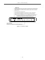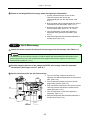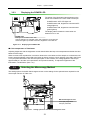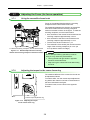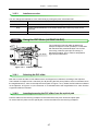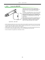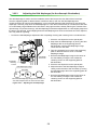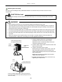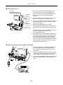
1
M498E 08.10.NF.1 (2/4) Inverted Metallurgical Microscope ECLIPSE MA200 Instructions Introduction Thank you for purchasing a Nikon product. This instruction manual is written for users of Nikon Inverted Metallurgical Microscope ECLIPSE MA200. To ensure correct usage, read this manual carefully before operating the product. • No part of this manual may be reproduced or transmitted in any form without prior written permission from Nikon. • The contents of this manual are subject to change without notice. • Although every effort has been made to ensure the accuracy of this manual, errors or inconsistencies may remain. If you note any points that are unclear or incorrect, please contact your nearest Nikon representative. • Some of the equipment described in this manual may not be included in the set you have purchased. • If you intend to use any other equipment with this product, read the manual for that equipment too. • If the equipment is used in a manner not specified by the manufacturer, the protection provided by the equipment may be impaired. 1 Safety Precautions To ensure correct and safe operation, read this manual before using the product. Warning and Caution Symbols Used in This Manual Although this product is designed and manufactured to be completely safe during use, incorrect usage or failure to follow the safety instructions provided may cause personal injury or property damage. To ensure correct usage, read this manual carefully before using the product. Do not discard this manual and keep it handy for easy reference. Safety instructions in this manual are marked with the following symbols to highlight their importance. For your safety, always follow the instructions marked with these symbols. Symbol Description Warning Disregarding instructions marked with this symbol may lead to serious injury or death. Caution Disregarding instructions marked with this symbol may lead to injury or property damage. Meaning of Symbols Used on the Product Symbol Description Caution for heat This marking on the back of the lamphouse calls your attention on the following (the position of this symbol is shown in Figure 1.1-3): • The lamphouse becomes extremely hot while the lamp is on and immediately after it is turned off. • Do not touch the lamphouse during and immediately after lighting to prevent the risk of burns. • Make sure that the lamphouse is sufficiently cool before the lamp replacement. 2 Safety Precautions WARNING 1. Intended product use The product should only be used for microscopic observation. Do not use this microscope for other purposes. Additionally, do not try to put a large sample on the stage if it is larger than the stage. 2. Do not disassemble Disassembling the microscope or the microscope system may result in electric shock or malfunctions. Damage or injury that may occur due to mishandling is unwarranted. Never attempt to disassemble any part other than the parts described in this manual. If you experience problems with the microscope or the microscope system, contact your nearest Nikon representative. 3. Read the instructions carefully To ensure safety, carefully read this manual and the manuals for other equipment used with this microscope. In particular, observe all warnings and cautions given at the beginning of each manual. 4. Ratings of the power supply The power supply circuit in this product is designed for AC power of 100 to 240 VAC and 50/60 Hz. Before connecting the power cord, check that the power supply to be used conforms to the voltage and frequency described above. Use of a non-conforming power line may result in equipment malfunction, failure or fire. 5. Power cord Be sure to use the specified power cord for the product. Using a wrong power cord may result in malfunctions or fire. The product is classified as subject to Class I protection against electrical shock. Make sure it is connected to an appropriate ground terminal (protective earth terminal). To prevent electrical shock, always turn off the power switch (set the switch to the “c” position) for the product before connecting or disconnecting the power cord. For specifications of the power cord, refer to “7. Specifications.” 6. Specified light source Use this product with a specified light source. The specified light source devices are shown as follows: For the episcopic illumination • Lamphouse Nikon 12V 50W Precentered Lamphouse (model name: LV-LH50PC) • Lamp Nikon 12V 50W longlife halogen lamp (model name: LV-HL50W) or 12V 50W shortlife halogen lamp from other manufacturers (model name: OSRAM HLX 64610, OSRAM HLX 64611, or PHILIPS 7027). For the diascopic illumination • Lamphouse Nikon 12V 100W Precentered Lamphouse LC (model name: D-LH/LC) • Lamp Nikon 12V 100W halogen lamp (model name: OSRAM HLX 64623 or PHILIPS 77241). • TI-PS 100W power supply If you wish to buy these lamps, please contact your nearest Nikon representative. 3 Safety Precautions 7. Heat from the light source The lamp and the lamphouse become extremely hot. To avoid burns, do not touch the lamphouse while the lamp is lit or for thirty minutes after it is turned off. Additionally, to avoid the risk of fire, do not place fabric, paper, or highly flammable volatile materials (such as gasoline, petroleum benzine, paint thinner, or alcohol) near the lamphouse while the lamp is lit or for about thirty minutes after it is turned off. 8. Air vents Do not block the air vents on the product and the lamphouse. If the air vents are blocked, the temperature inside the product will rise. And it may result in damage or fire. 9. To use the HG Precentered Fiber Illuminator To perform the epi-fl microscopy with this product, the brightness of the specified light source may be less than the desired brightness. In this case, connect an external light source that has a mercury lamp, Nikon INTENSILIGHT HG Precentered Fiber Illuminator (model: C-HGFI manual type, or C-HGFIE motorized type) to MA200 to be used. • Handling the mercury lamp When using the mercury lamp, you must take great care of the lamp. Read the instruction manual for the light source and follow the instructions and cautions. • Ultraviolet light from an external light source If you use an external light source other than the specified ones and that has a mercury lamp, the light source radiates ultraviolet light, which is harmful to the eyes and skin, from the emission port. Direct viewing of light from these lamps may result in snow blindness at a light case or blindness at the worst case. To prevent injury, be sure to attach a fiber illuminator to the microscope. The light source device is required to be connected to the microscope whenever the light source device is energized. Do not turn on the light source if it is not connected to the microscope, and do not disconnect the light source from the microscope while the light source is lit. When disconnecting the light source from the microscope, turn off the power to the light source, and then unplug the power cord from the outlet. 4 Safety Precautions CAUTION 1. Handle with care This product is a precision optical instrument. Handle the microscope system with care to avoid shock on impact. In particular, objectives may loose accuracy when exposed to even a weak physical shock. 2. Do not wet the microscope If the product gets wet, a short circuit may cause malfunction or abnormal heating of the microscope. If you accidentally spill water on the microscope, immediately turn off the power switch (set the switch to the “c” side) and unplug the power cord from the outlet. Then, wipe off the water with a piece of dry cloth. If water enters a component, immediately suspend use of this product, disconnect the power cord from the outlet, and contact your nearest Nikon representative. 3. Weak electromagnetic waves The product emits weak electromagnetic waves. The accuracy of any precision electronic equipment may be adversely affected if positioned too close. To prevent bad influences, locate such electronic equipment away from the microscope system. If a TV or radio reception is affected, move the TV or radio set farther from the product. 4. Installation location This product is a precision optical instrument. The usage or storage in an inappropriate environment may result in malfunctions or poor performance. Consider the following factors when selecting an installation location: • Select an installation location with a temperature from 0 to +40°C and a relative humidity of 85% or less (there should be no condensation). Select a storage location with a temperature from -20 to +60°C and a relative humidity of 90% or less (there should be no condensation). If installed or stored in a location subject to high temperatures and humidity, mold or condensation may form on the lens, resulting in lowered performance and possible damage to the microscope. • Avoid a brightly lit location, such as exposed to direct sunlight or directly under a room light. If there is excessive ambient light, the image may not clearly be visible. • Always install the product with a surrounding clear area of 10 cm or more. • Install the product in a location free from considerable dust or dirt. • Install the product on a flat surface with little vibration. • Install the product on a sturdy desk or table for the base of the microscope system. • Select a layout that allows easy removal of the power cord from the AC inlet of the product in the event of an emergency. • Do not install in a narrow space such as a shelf or locker. • Do not place anything on the product. • Cover the product to avoid dust when storing. • For details about the operating environment and storage environment, refer to “7. Specifications.” 5. Cautions on moving the microscope • This product is a precision optical instrument. Handle it carefully and do not subject it to a strong physical shock. (In particular, objectives may loose accuracy when exposed to even a weak physical shock.) • Securely hold the microscope at the front bottom and rear bottom when carrying it. 5 Safety Precautions • Do not hold the focus knobs, eyepiece tube, lamphouse, stage, and so on, when carrying the microscope. They may come off and may cause serious injury or malfunction. • Be careful not to pinch your hands or fingers during transportation. 6. Cautions on assembling the microscope • Be careful not to pinch your fingers or hands during assembly. • Scratches or fingerprints on the optical components, including lenses or filters etc., will adversely affect the image. Be careful not to scratch or touch the lens surfaces. 7. Cautions on replacing lamps • To prevent burn injuries, wait at least 30 minutes after the lamp is turned off to give it sufficient time to cool down when replacing lamps. • To prevent electrical shock and damage to the microscope, always turn off the power switch (set the switch to the “c” side) and unplug the power cord from the outlet before attaching or detaching the lamphouse. • Never touch the glass surface of the lamp with bare hands. Doing so may cause fingerprints, grease, etc., to generate ghost images on the lamp surface, reducing the illumination. If you do get any fingerprints or dirt on the lamp, wipe them clean. • Make sure the lamphouse cover is securely fitted to the lamphouse after replacing lamps. Never turn on the lamp with the lamphouse cover removed. • When you dispose of the replaced lamp, do not break it. Instead, dispose of the used lamp as industrial waste or dispose of it according to the local regulations and rules. 8. Cable routing Make sure the cables are routed properly. Do not bring the cables into contact with the lamphouse. If a cable comes into contact with the lamphouse, the cable sheath may melt and it may result in an electrical shock or fire. Additionally, connect the cables by placing them into the cable keeper on the rear of the microscope main body. 6 Contents Introduction ....................................................................................................................................................................... 1 Safety Precautions............................................................................................................................................................ 2 Warning and Caution Symbols Used in This Manual ................................................................................................. 2 Meaning of Symbols Used on the Product ................................................................................................................. 2 WARNING .......................................................................................................................................................... 3 CAUTION ........................................................................................................................................................... 5 1. Part Name and Function ........................................................................................................................................ 10 2. Microscopy ............................................................................................................................................................. 14 2.1 3. Bright-field Microscopy under the Episcopic Illumination .............................................................................. 16 2.2 Dark-field Microscopy under the Episcopic Illumination ................................................................................ 19 2.3 Polarization Microscopy under the Episcopic Illumination (simplified/sensitive color)................................... 20 2.4 Differential Interference Contrast Microscopy under the Episcopic Illumination............................................ 21 2.5 Epi-fl Microscopy........................................................................................................................................... 22 2.6 Bright-field Microscopy under the Diascopic Illumination .............................................................................. 24 2.7 Polarization Microscopy under the Diascopic Illumination (simplified/sensitive color)................................... 28 Operation Details.................................................................................................................................................... 29 3.1 3.2 Power ON/OFF ............................................................................................................................................. 29 3.1.1 Power of the microscope............................................................................................................... 29 3.1.2 Power supply of the lamp .............................................................................................................. 29 Illumination.................................................................................................................................................... 30 3.2.1 Brightness control and illumination ON/OFF ................................................................................. 30 3.2.2 Switching the Internal/External brightness control......................................................................... 30 3.2.3 Displaying the POWER LED ......................................................................................................... 31 3.3 Selecting the Microscopy Method ................................................................................................................. 31 3.4 Eyepiece Tube .............................................................................................................................................. 33 3.4.1 Selecting optical path .................................................................................................................... 33 3.4.2 Adjusting the eyelevel risers.......................................................................................................... 34 3.5 Adjusting the Interpupillary Distance............................................................................................................. 34 3.6 Adjusting the Diopters................................................................................................................................... 35 3.7 Adjusting the Focus (for focus operation) ..................................................................................................... 36 3.8 3.9 3.7.1 Using the coarse/fine focus knob .................................................................................................. 36 3.7.2 Adjusting the torque for the coarse focus ring ............................................................................... 36 Placing the Sample and Operating the Stage ............................................................................................... 37 3.8.1 Placing the sample........................................................................................................................ 37 3.8.2 Changing the Observation Position............................................................................................... 38 Operating the Revolving Nosepiece and the Objective................................................................................. 39 3.9.1 Revolving nosepiece in combination with the objective................................................................. 39 3.9.2 Changing the objectives ................................................................................................................ 39 3.9.3 Displaying the address for the revolving nosepiece ...................................................................... 39 3.10 Filter.............................................................................................................................................................. 40 3.11 Adjusting the Field Diaphragm (for the episcopic Illumination) ..................................................................... 41 3.12 Adjusting the Aperture Diaphragm (for the episcopic illumination) ................................................................ 42 3.13 Using the Polarizer/Analyzer Unit (MA2-PA/MA2-UPA) ................................................................................ 43 3.13.1 Inserting/removing the polarizer/analyzer from the optical path .................................................... 43 7 Contents 3.13.2 3.14 Using the λ Plate (MA2-λP)........................................................................................................................... 45 3.14.1 3.15 3.16 3.17 3.15.1 Inserting/removing the DIC prism from the optical path ................................................................ 46 3.15.2 Setting the DIC prism .................................................................................................................... 46 3.15.3 Interference color .......................................................................................................................... 47 Using the DIC Slider (LV-DIHC/LV-DIC) ........................................................................................................ 47 3.16.1 Selecting the DIC slider................................................................................................................. 47 3.16.2 Inserting/removing the DIC slider from the optical path................................................................. 47 3.16.3 Interference color .......................................................................................................................... 48 Using the Analyzer Slider (D-DA).................................................................................................................. 48 3.20 Inserting/removing the λ plate from the optical path...................................................................... 49 Using the Fluorescent Unit (MA2-FL)............................................................................................................ 50 3.19.1 Inserting/removing the fl filter from the optical path....................................................................... 50 3.19.2 Excitation light filter (EX filter) ....................................................................................................... 51 3.19.3 Barrier filter (BA filter).................................................................................................................... 52 Using the Scale Slider (MA2-GR/MA2-MR) .................................................................................................. 53 3.20.1 Grain scale slider (MA2-GR) ......................................................................................................... 53 3.20.2 Scale slider (MA2-MR) .................................................................................................................. 54 3.21 Using the Intermediate Magnification Unit (MA2-MC) ................................................................................... 55 3.22 Using the HG Precentered Fiber Illuminator (C-HGFI/C-HGFIE) .................................................................. 56 3.22.1 3.23 4. Inserting/removing the analyzer from the optical path................................................................... 48 Using the λ Plate (D-LP) ............................................................................................................................... 49 3.18.1 3.19 Inserting/removing the λ plate ....................................................................................................... 45 Using the DIC Slider (L-DIHC/L-DIC)............................................................................................................ 46 3.17.1 3.18 Adjusting the polarizer direction .................................................................................................... 44 Procedure for turning on the power switch .................................................................................... 56 Using the supporting pillar for dia-Illuminator 100W (MA2-DP)..................................................................... 57 3.23.1 Procedure for turning on the power switch .................................................................................... 57 3.23.2 Focusing and centering the condenser ......................................................................................... 58 3.23.3 Adjusting the field diaphragm (for the diascopic illumination)........................................................ 59 3.23.4 Adjusting the aperture diaphragm (for the diascopic illumination) ................................................. 60 3.23.5 Diascopic illumination filter ............................................................................................................ 60 3.23.6 Condenser refocusing clamp......................................................................................................... 61 3.23.7 Condenser mount rotation............................................................................................................. 61 3.23.8 Polarizer slider (T-P2), λ plate (TI-DIC) ......................................................................................... 62 3.24 Using the Supporting Arm (MA2-MP)............................................................................................................ 64 3.25 Using the DS Camera Control Unit (DS-L2).................................................................................................. 65 3.25.1 Procedure for turning on the power............................................................................................... 65 3.25.2 Displaying the microscope info menu............................................................................................ 65 3.25.3 Measurement corresponding to the magnification value of the microscope .................................. 66 3.25.4 Recording the microscope info while saving the image................................................................. 66 3.25.5 Connecting with the DS camera head switcher (DS-SW: Camera switch BOX, optional) ............. 67 Assembly ................................................................................................................................................................ 68 4.1 About the System.......................................................................................................................................... 70 4.2 Combination List for the Unit......................................................................................................................... 71 8 Contents 4.3 4.4 4.5 4.6 Network Connection...................................................................................................................................... 73 4.3.1 Unit system capable of establishing network................................................................................. 73 4.3.2 Viewing user control options and status displays on a PC or the DS-L2 ....................................... 74 4.3.3 Registering information on the objective ....................................................................................... 76 4.3.4 Procedure for turning on the power switch .................................................................................... 76 The LV-LH50PC Lamphouse and the Lamp.................................................................................................. 77 4.4.1 Attaching the lamphouse............................................................................................................... 77 4.4.2 Replacing the lamp ....................................................................................................................... 78 Revolving Nosepiece .................................................................................................................................... 78 4.5.1 Attaching the nosepiece ................................................................................................................ 78 4.5.2 Cable connection for the manual revolving nosepiece and the MA200......................................... 79 4.5.3 Connecting the motorized nosepiece and the Nosepiece Controller 2.......................................... 79 Stage............................................................................................................................................................. 80 4.6.1 4.7 Objectives ..................................................................................................................................................... 81 4.8 Eyepiece Tube .............................................................................................................................................. 81 4.9 Eyepieces ..................................................................................................................................................... 81 4.10 Grain Scale Slider/Scale Slider ..................................................................................................................... 82 4.11 Filters ............................................................................................................................................................ 82 4.12 Various Sliders Available for Attaching the Revolving Nosepiece ................................................................. 83 4.13 4.12.1 L-DIC/L-DIHC slider (single NR method) ...................................................................................... 83 4.12.2 LV-DIC/LV-DIHC slider (Senarmont method)................................................................................. 84 4.12.3 D-DA analyzer slider, D-LP λ plate ................................................................................................ 84 Polarizer/analyzer Unit and Fluorescent Unit ................................................................................................ 85 4.13.1 5. 6. 7. Sample holder ............................................................................................................................... 80 MA2-λP λ plate.............................................................................................................................. 85 4.14 Intermediate Magnification Unit..................................................................................................................... 86 4.15 External Light Source.................................................................................................................................... 87 4.15.1 C-HGFI/C-HGFIE HG Precentered Fiber Illuminator..................................................................... 87 4.15.2 Attaching the MA2-DP supporting pillar for dia-Illuminator 100W.................................................. 88 4.16 Supporting Arm (for DS-L2) .......................................................................................................................... 94 4.17 Eyelevel Risers ............................................................................................................................................. 96 4.18 Camera Adapter............................................................................................................................................ 97 4.19 Power Cord ................................................................................................................................................... 97 Troubleshooting ..................................................................................................................................................... 98 5.1 Viewing Problems and Control Problems...................................................................................................... 98 5.2 Electrical System Problems ........................................................................................................................ 101 Care and Maintenance ......................................................................................................................................... 102 6.1 Cleaning the Lenses and Filters.................................................................................................................. 102 6.2 Cleaning the Painted Parts, Plastic Parts, and Printed Parts ...................................................................... 102 6.3 Storage ....................................................................................................................................................... 103 6.4 Regular Inspections (fee charged) .............................................................................................................. 103 Specifications....................................................................................................................................................... 104 9 1 Part Name and Function Eyepiece Sample holder 10X, 12.5X, 15X (and 10X are equipped with the mask eyepiece.) Eyepiece tube (Figure illustrates the MA2-TI3.) The stage is equipped with the standard sample holder (with a sample clip). (Refer to 3.8.) Sample clip Binocular eyepiece may also be used. (Refer to 3.4, 3.5, and 3.6.) Stage (Figure illustrates the MA2-SR.) (Refer to 3.8.) Objectives (Refer to 3.9.) Nosepiece (Figure illustrates the MA2-NUI5.) Quintuple, sextuple and septuple revolving nosepieces may be used. (Refer to 3.9.) The DIC slider, analyzer slider etc., can be attached, depending on the revolving nosepiece used. Stage (forward/backward) movement knob for the Y direction Stage (left /right) movement knob for the X direction Display Fine focus knob (Refer to Figure 1.1-2.) (Refer to 3.7.) Located also on the left. Front-cover fixing bolt Aperture diaphragm dial (Refer to 3.12.) BD field changeover lever Press (BF): Bright-field Pull (DF): Dark-field (Refer to 3.3.) Scale slider slot (Refer to 3.20.) Attach the grain scale slider or scale slider. Aperture diaphragm centering holes Field diaphragm dial (Refer to 3.11.) Operation port for the polarizer/analyzer unit and the fluorescent unit (Refer to 3.13 and 3.19.) To perform the polarization microscopy, differential interference contrast microscopy or fluorescent microscopy, remove the front cover to attach the desired unit for the microscopy to be performed. Field diaphragm centering holes Figure 1.1-1 Front view, Right-side view 10 Chapter 1 Part Name and Function POWER LED Displays ON/OFF for the power switch or the light-status for the illumination lamp. Additionally, the display status remains the same when an external PC is in use. Power switch OFF: LED turns off Power switch ON; Brightness control dial OFF: Orange LED lights up Power switch ON; Brightness control dial ON: Green LED lights up Note: The Power LED Message is only compatible with the lamphouse of the MA200 main body for the episcopic illumination, and the HG precentered fiber illuminator (C-HGFIE motorized type). Address display Address of the objective in the optical path lights up. Figure 1.1-2 Front view 11 Display Chapter 1 Part Name and Function Supporting Pillar for Dia-Illuminator 100W/Supporting Arm for DS-L2 attaching part Optical path changeover lever (eyepiece tube/back port) (Refer to 3.23 and 3.24.) Attach the supporting pillar for dia-Illuminator 100W or the supporting arm for DS-L2. (Refer to 3.4.) Press: Eyepiece tube/back port =100/0 Tool storage Stores the supplied hexagonal wrench and two hexagonal screwdrivers. Rear-panel clamp screw Rear-panel Eyepiece tube clamp screw Pull: Eyepiece tube/back port =55/45 Attaching part for the intermediate magnification unit (Refer to 3.21.) Attach this unit to change observation magnifications. Remove the rear-panel cover for cable connection of the revolving nosepiece. Optical path changeover lever (vertical tube/binocular tube) (Refer to 3.4.) Press: Binocular/vertical tube=100/0 Pull: Binocular/vertical tube=0/100 Vertical tube Binocular tube Back port Air vents Cable keeper Keeps cables inside. “CAUTION for heat” symbol Clamp screws for the filter turret Epi illumination lamphouse (LV-LH50PC Lamphouse) Attach an HG precentered fiber illuminator instead of LV-LH 50PC Lamphouse, if necessary. Signal cable hole for the nosepiece controller 2 Connectors Brightness control dial Lamp air vents (Refer to 3.2.) Adjusts the brightness of the lamp. (Refer to Figure 1.1-4.) AC inlet Connects the power cord exclusive for the region of the product used (optional). Power switch Fine focus knob Filter turret (Refer to 3.10.) Switch the turret when the ND filter or other filters is/are turned. (Refer to 3.1.) Set the switch to the “|” side to turn on the power, or to the “c” side to turn off the power. Coarse torque adjustment ring (Refer to 3.7.) Adjusts the rotation residence. When the power is turned on, the POWER LED on the front-display lights up. Figure 1.1-3 Left view, Rear view 12 (Refer to 3.7.) Focus on the sample by slightly lifting/lowering the revolving nosepiece with the fine knob. Coarse focus knob (Refer to 3.7.) Focus on the sample roughly lifting/lowering the revolving nosepiece with the coarse knob. Chapter 1 Part Name and Function Lamphouse connector [LAMP DC12V50W] Connects the cord on the epi illumination lamphouse (12V 50W Precentered Lamphouse). Internal/External brightness control changeover switch [EXTERNAL ON/OFF] RS232C connector [HGFIE] Connects the C-HGFIE HG Precentered Fiber Illuminator. (Refer to 3.2.2, 3.22.1, and 3.23.1.) ON: Adjusts the brightness on PC; RS232C connector [NCNT] OFF: Adjusts the brightness on the microscope. Connects the LV-NCNT2 control unit for the motorized nosepiece. USB connector [USB] Connects a PC or the DS-L2. Figure 1.1-4 Connectors on the rear About product parts names in this manual The right column of the table below shows the product parts names described in this manual. Package names Parts names in the ECLIPSE MA200 Instructions MA2-TI3 Trinocular Eyepiece Tube ESD (erect image) MA2-TI3 Trinocular Eyepiece Tube MA2-NUI5 Intelligent Universal Quintuple Nosepiece ESD MA2-NUI5 Revolving Nosepiece MA2-MC Magnification Module MA2-MC Intermediate Magnification Unit Fl Filter Block MA2-FL G (Other types than G are available.) General name: MA2-FL Fluorescent Unit MA2-GR Grain Size Slider MA2-GR Grain Scale Slider MA2-PA Polarizing Filter Cube MA2-PA Polarizer/Analyzer Unit MA2-UPA Polarizing Filter Cube with 1/4λPlate MA2-UPA Polarizer/Analyzer Unit MA2-SRSH 10 Specimen Holder (Other types than SRSH 10 are available.) General name: Sample Holder 13 2 Microscopy This chapter describes the procedure of each microscopy. See Table 2.1 for the items required for each microscopy. • Refer to “4. Assembly,” when the product has not been assembled yet. • For detailed information about operations of parts of the product, refer to “3. Operation Details.” • Notes on using an external light source: The procedures described on the episcopic illumination in 2.1 to 2.5 are based on use of the light source of the MA200 main body with the LV-LH50PC Lamphouse attached. When using an external light source to perform the microscopy, follow the notes below. • The procedure on how to turn the power switch to ON: Turn on the power switch on the external device in advance, then turn on the MA200 main body. • Setting the Internal/External brightness control changeover switch of the MA200 main body: Sets to ON (external mode). • Adjusting the brightness of the light source: Adjusts the brightness on the external light source. • To perform the epi-fl microscopy using the C-HGFI/C-HGFIE HG Precentered Fiber Illuminator as the external light source, screw the compensation filter supplied with the fiber adapter into the MA2-FL fluorescent unit. (Refer to 4.15.1.) 14 Chapter 2 Table 2.1 Microscopy BF microscopy under the epi illumination Page Illuminator p.16 to p.18 Microscopy Items required for the microscopy Revolving nosepiece 5 revo., 6 revo., 7 revo. Objective Other items required • For EPI objectives with 5 revo., LU nosepiece adapter M32-25 required ⎯ • For 6 or 7 revo., BD objective unavailable DF microscopy under the epi illumination p.19 Simplified polarization microscopy under the epi illumination p.20 5 revo. only BD objective only ⎯ 5 revo., 6 revo., 7 revo. • For EPI objectives with 5 revo., LU nosepiece adapter M32-25 required • For 6 or 7 revo., BD objective unavailable DIC microscopy p.21 to p.22 under the epi illumination 5 revo., 6 revo. LU EPI objectives or LU BD objective only • For EPI objectives with 5 revo., LU nosepiece adapter M32-25 required LV-LH 50PC Lamphouse or C-HGFI/C-HGFIE HG Precentered Fiber Illuminator • BD objective unavailable for 6 revo. • MA2-PA/MA2-UPA polarizer/analyzer unit • For the sensitive color polarization microscopy, MA2-λP λ plate available For 5 revo.: • MA2-PA polarizer/analyzer unit • L-DIHC/L-DIC slider (single NR method) • For the sensitive color polarization microscopy, the MA2-λP λplate available For 6 revo.: • MA2-UPA polarizer/analyzer unit • LV-DIHC/LV-DIC slider (Senarmont method) • For the sensitive color polarization microscopy, the MA2-λP λplate available Epi-fl microscopy p.22 5 revo., 6 revo., 7 revo. LU EPI objectives or LU BD objective only • MA2-FL fluorescent unit • For EPI objectives with 5 revo., LU nosepiece adapter M32-25 required • For 6 or 7 revo., BD objective unavailable BF microscopy under the dia illumination Simplified polarization microscopy under the dia illumination p.23 to p.26 p.27 5 revo., 6 revo., 7 revo. Supporting pillar for dia-Illuminator 100W (+ condenser, D-LH/LC Lamphouse, 12V 100W halogen lamp) • For EPI objectives with 5 revo., LU nosepiece adapter M32-25 required ⎯ • For 6 or 7 revo., BD objective unavailable 5 revo., 6 revo., 7 revo. • For EPI objectives with 5 revo., LU nosepiece adapter M32-25 required • For 6 or 7 revo., BD objective unavailable • T-P2 polarizer • MA2-PA/MA2-UPA polarizer/analyzer unit (for 6 revo., the D-DA analyzer is also available) • For the sensitive color polarization microscopy, TI-DIC λplate available (for 6 revo., the D-LP λplate is also available) 15 Chapter 2 2.1 Microscopy Bright-field Microscopy under the Episcopic Illumination Turn on the power to light up the episcopic illumination lamp. 1 Turn on the power switch. (See 3.1.1.) The power LED on the front is lit. 2 Be sure that the Internal/External brightness control changeover switch is set to OFF “internal mode.” (See 3.2.2.) 3 Turn the brightness control dial to light up the lamp. (See 3.2.1.) 1-2 1-1 1-3 1-1 16 Chapter 2 Microscopy Set the microscope for the bright-field microscopy under the episcopic illumination. If the current unit is the one shown in the column at the right edge under “Other items required” in Table 2.1, pull out each item from the optical path. 1 Push in the optical path changeover lever for the eyepiece tube and select 100% for the binocular eyepiece. (See 3.4.1.) 2-4 2-1 2 Push in the eyepiece tube/back port changeover lever to select 100% for the eyepiece tube. (See 3.4.1.) 2-2 2-5, 6 3 Push in the BD field changeover lever to select the “BF (bright-field)” position. (See 3.3.) 2-4 4 Turn the revolving nosepiece to place the 10X objective into the optical path. (See 3.9.2) The nosepiece addresses (1 to 7) on the front-display light up to indicate the position of the revolving nosepiece. (See 3.9.3.) 2-6 5 Place the NCB11 filter in the filter turret into the optical path and compensate color temperature. (See 3.10) 2-3 2-7 6 Adjust the brightness roughly with the brightness control dial and the desired ND filter in the filter turret. (See 3.2.1 and 3.10.) 7 Turn the field diaphragm dial and the aperture diaphragm dial counter-clockwise to the limit to fully open the field diaphragm and the aperture diaphragm for the episcopic illumination. (See 3.11 and 3.12.) Place the sample onto the stage and adjust the focus and the brightness. 1 Use the sample holder according to the selected sample. Place the sample onto the stage and move the stage using the stage movement knob for the X/Y direction so that the observation position comes to the center of the view-field. (See 3.8.) 3-1 2 Turn the coarse/fine focus knobs and focus on the target. (See 3.7.) 3 Turn the brightness control dial to adjust the brightness of the episcopic illumination. (See 3.2.1.) 3-2 3-3 3-1 Adjust the diopter and the interpupillary distance. 1 Adjust the interpupillary distance. (See 3.5.) 2 Adjust the diopter. (See 3.6.) 17 Chapter 2 Microscopy Set the desired magnification and observe the sample. 5-1 1 Turn the revolving nosepiece to place the objective of a desired magnification into the optical path. (See 3.9.2.) 2 Turn the coarse/fine focus knobs and refocus on the sample. (See 3.7.) 5-6 3 Turn the brightness control dial to adjust the brightness of the episcopic illumination. (See 3.2.1.) 4 Turn the field diaphragm dial so that the field diaphragm image circumscribes the view-field. (See 3.11.) 5-2 5-3 5-5 5-4 5 Turn the aperture diaphragm dial so that the aperture diaphragm image becomes 70 to 80% of the numerical aperture of the objective. (See 3.12.) 6 Adjust the brightness with the desired ND filter in the filter turret. (See 3.10.) Note: Adjusting focus It may be difficult to focus on a sample with small contrast, such on a polished surface. In a case like this, stop down the field diaphragm so that its image can be seen in the view-field, and try to focus on the frame of the diaphragm image. When the frame is in focus, the sample is in focus just as well. 18 Chapter 2 2.2 Microscopy Dark-field Microscopy under the Episcopic Illumination Attach the items required for the dark-field microscopy under the episcopic illumination to the microscope. (See Table 2.1.) Focus on the sample with the bright-field microscopy under the episcopic illumination. (See Pages 16 and 17.) Set the microscope for the dark-field microscopy under the episcopic illumination. 3-1 1 Turn the revolving nosepiece to place the objective of a desired magnification into the optical path. (See 3.9.2.) 2 Pull out the BD field changeover lever to select the “DF (dark-field)” position. (See 3.3.) 3-4 The aperture diaphragm and the field diaphragm are fully opened. (The dial positions do not change.) When the polarizer/analyzer or the fl filter is placed into the optical path, it is automatically excluded. 3-3 3 Turn the brightness control dial to adjust the brightness of the episcopic illumination. (See 3.2.1.) 3-2 4 Adjust the brightness with the desired ND filter in the filter turret. (See 3.10.) Return to the bright-field microscopy under the episcopic illumination. 1 Push in the BD field changeover lever to select the “BF (bright-field)” position. (See 3.3.) The aperture diaphragm and the field diaphragm automatically return to the previous positions. (The dial positions do not change.) 2 Turn the brightness control dial to adjust the brightness of the episcopic illumination. (See 3.2.1) 3 Adjust the brightness with the desired ND filter in the filter turret. (See 3.10.) 19 Chapter 2 2.3 Microscopy Polarization Microscopy under the Episcopic Illumination (simplified/sensitive color) Attach the items required for the polarization microscopy under the episcopic illumination to the microscope. (See Table 2.1.) Focus on the sample with the bright-field microscopy under the episcopic illumination. (See Pages 16 to 17.) Set the microscope for the polarization microscopy under the episcopic illumination. 3-1 3-4 1 Turn the revolving nosepiece to place the objective of a desired magnification into the optical path. (See 3.9.2.) 2 Push in the polarizer/analyzer unit to the second click-stop position and place it into the optical path. (See 3.13.1.) 3-6 3 Turn the polarizer rotation ring to the crossed Nicol’s position. (See 3.13.2.) 4 To perform the sensitive color polarization microscopy, insert the λplate into the polarizer/analyzer unit and place it into the optical path. (See 3.14.1.) 3-5 3-3, 7 3-2 5 Turn the brightness control dial to adjust the brightness of the episcopic illumination. (See 3.2.1.) 6 Adjust the brightness with the desired ND filter in the filter turret. (See 3.10.) 7 Turn the polarizer rotation ring to adjust the polarization while observing the image. Return to the bright-field microscopy under the episcopic illumination. 1 Pull the analyzer/polarizer unit to the first click-stop position to remove the analyzer/polarizer from the optical path. (See 3.13.1.) 2 Both the λplate and the polarizer/analyzer unit are removed from the optical path. (See 3.14.1.) 3 Turn the brightness control dial to adjust the brightness of the episcopic illumination. (See 3.2.1.) 4 Adjust the brightness with the desired ND filter in the filter turret. (See 3.10.) 20 Chapter 2 2.4 Microscopy Differential Interference Contrast Microscopy under the Episcopic Illumination Attach the items required for the differential interference contrast (DIC) microscopy under the episcopic illumination to the microscope. (See Table 2.1.) Focus on the sample with the bright-field microscopy under the episcopic illumination. (See Pages 16 and 17.) Set the microscope for the DIC microscopy under the episcopic illumination. 3-5 3-1 3-4 1 Turn the revolving nosepiece to place the objective of a desired magnification into the optical path. (See 3.9.2.) 2 Push in the polarizer/analyzer unit to the second click-stop position and place it into the optical path. (See 3.13.1.) 3-7 3 Turn the polarizer rotation ring to the crossed Nicol’s position (See 3.13.2.) 4 Attach the DIC slider to the slot on the revolving nosepiece to place the DIC prism into the optical path. (See 3.15.1 or 3.16.2.) 3-6 3-3, 5 3-2 5 Set the interference color. (See 3.15.3 or 3.16.3.) For using the L-DIHC/L-DIC slider, turn the prism movement knob, whereas for using the LV-DIHC/LV-DIC slider, turn the polarizer rotation ring of the polarizer/analyzer unit. In either case, the interference color changes continuously from dark color, gray to sensitive red-violet. 6 Turn the brightness control dial to adjust the brightness of the episcopic illumination. (See 3.2.1.) 7 Adjust the brightness with the desired ND filter in the filter turret. (See 3.10.) ■ Sensitive color microscopy You can perform the sensitive color DIC microscopy using the λ plate placed into the polarizer/analyzer unit. If the λ plate is placed into the optical path in the crossed Nicol’s position (on dark background), the background is set to sensitive red-violet. This improves the contrast of the image to the highest degree. If you turn the polarizer rotation ring to pale-blue for background change when the λ plate is inserted, the interference image will resemble the dark contrast image in the phase contrast microscopy. Select the background color to achieve the desired contrast, if the phase contrast ratio varies intensively (for the rough, uneven surface of sample). 21 Chapter 2 Microscopy Return to the bright-field microscopy under the episcopic illumination. 1 Pull the polarizer/analyzer unit to the first stop-click position and remove the polarizer/analyzer from the optical path. (See 3.13.1.) 2 Both the λplate and the polarizer/analyzer unit are removed from the optical path. (See 3.14.1.) 3 Detach the DIC slider to remove the DIC prism from the optical path. (See 3.15.1 or 3.16.2.) 4 Turn the brightness control dial to adjust the brightness of the episcopic illumination. (See 3.2.1.) 5 Adjust the brightness with the desired ND filter in the filter turret. (See 3.10.) 2.5 Epi-fl Microscopy Attach the items required for the epi-fl microscopy to the microscope. (See Table 2.1.) To perform the epi-fl microscopy using the C-HGFI/C-HGFIE HG Precentered Fiber Illuminator as the external light source, screw the compensation filter supplied with the fiber adapter into the MA2-FL fluorescent unit. (Refer to 4.15.1.) Find the target and focus on the sample by BF/DF microscopy under the episcopic illumination. (See Pages 16 to 17, and 19.) Set the microscope for the epi-fl microscopy. 3-1 1 Turn the revolving nosepiece to place the objective of a desired magnification into the optical path. (See 3.9.2.) 2 Turn the BD field changeover lever to the “BF (bright-field)” position. (See 3.3.) 3 Push the attached fluorescent unit into the second click-stop position and place the fl filter into the optical path (See 3.19.1.) 3-5 4 Turn the brightness control dial to adjust the brightness. (See 3.2.1.) 5 Adjust the brightness with the desired ND filter in the filter turret. (See 3.10.) 3-4 3-3 3-2 22 Chapter 2 Microscopy Return to the bright-field or dark-field microscopy under the episcopic illumination. 1 Turn the BD field changeover lever to the “BF (bright-field)” or “DF (dark-field)” position. (See 3.3.) 2 Turn the brightness control dial to adjust the brightness. (See 3.2.1.) 3 Adjust the brightness with the desired ND filter in the filter turret. (See 3.10.) 23 Chapter 2 2.6 Microscopy Bright-field Microscopy under the Diascopic Illumination Attach the items required for the bright-field microscopy under the diascopic illumination. (See Table 2.1.) Turn on the power to light up the diascopic illumination lamp. (See 3.23.1.) 1 Set the brightness control dial to OFF on the MA200 main body. (See 3.2.1.) 2 Turn on the TI-PS100W power supply connected to the supporting pillar for dia-Illuminator. 3 Set the MA200 main body to ON. The power LED on the front is lit. The light intensity control dial for the TI-PS100W power supply is enabled. 2-4 4 Turn the light intensity control dial on the TI-PS100W power supply to adjust the illumination. You can change the output voltage within 1V to 12V. When the output voltage is set to around 9V, the ideal optical color reproduction generates. 2-2 2-3 2-1 2-3 24 Chapter 2 Microscopy Set the microscope for the bright-field microscopy under the diascopic illumination. When the “Other items required” (See the column at the right edge of Table 2.1.) is used for the episcopic illumination, remove each attachment from the optical path in advance. 1 Push in the optical path changeover lever for the eyepiece tube and select 100% for the binocular eyepiece. (See 3.4.1.) 2 Push in the BD field changeover lever to select the “BF (bright-field)” position. (See 3.3.) 3-4, 5 3-6 3 Turn the revolving nosepiece to place the 10X objective into the optical path. (See 3.9.2.) 3-8 3-1 3-7 3-9 3-5 3-3 3-2 4 Place the NCB filter on the supporting pillar for dia-Illuminator into the optical path and compensate the color temperature. (See 3.23.5.) 5 Adjust the brightness of the diascopic illumination roughly with the light intensity control dial for the TI-PS100W power supply and the desired ND filter on the pillar illuminator. (See 3.23.1 and 3.23.5.) 6 Turn the field diaphragm dial for the supporting pillar for dia-Illuminator clockwise to the limit and fully open the field diaphragm for the diascopic illumination. (See 3.23.3.) 7 Turn the aperture diaphragm lever for the system condenser clockwise to the limit and fully open the field diaphragm. (See 3.23.4) 8 Turn the condenser focus knobs for the supporting pillar for dia-Illuminator and lower the condenser mount to the limit. (See 3.23.6.) • When the ELWD condenser lens is attached to the system condenser, lower the condenser mount approximately 1 cm from the upper limit. • When the ELWD-S condenser is used, lower the condenser mount approximately 2 cm from the upper limit. 9 Turn the turret of the condenser to the “A” position to place the bright-field condenser cassette into the optical path. 25 Chapter 2 Microscopy Place the sample onto the stage to adjust the focus. 1 Use the sample holder according to the selected sample. Place the sample onto the stage and move the stage using the stage movement knob for the X/Y direction so that the observation position comes to the center of the view-field. (See 3.8.) 4-2 4-1 2 Turn the coarse/fine focus knobs and focus on the sample. (See 3.7.) 4-1 Adjust the diopter and the interpupillary distance. 1 Adjust the interpupillary distance. (See 3.5.) 2 Adjust the diopter. (See 3.6.) Adjust the focus again. 1 Look into the eyepieces. Move the stage to bring the observation target into the center of the view-field using the stage movement knob for the X/Y direction. 2 Look into the eyepieces. Adjust the focus onto the sample by turning the coarse/fine focus knob. 6-1, 2 6-1 6-2 26 Chapter 2 Microscopy Center the condenser. (See 3.23.2.) 1 Be sure that the objective is set to the 10X objective. If not, turn the revolving nosepiece to place the 10X objective into optical path. 7-2, 6 2 Stop down the field diaphragm by turning the field diaphragm dial on the supporting pillar for dia-Illuminator until the field diaphragm image comes into the view-field. 7-3 7-4, 7 3 Turn the condenser focus knob for the supporting pillar for dia-Illuminator to focus on the field diaphragm image. 4 Turn the two condenser centering screws for the pillar illuminator to move the field diaphragm images to the center of the view-field. 5 Turn the revolving nosepiece to place the 40X objective into the optical path. 7-1, 5 6 Turn the field diaphragm dial for the supporting pillar for dia-Illuminator until the diaphragm image becomes nearly the same as the view-field. 7 Turn the two condenser centering screws on the supporting pillar for dia-Illuminator to move the field diaphragm images to the center of the view-field. Set the desired magnification and observe the sample. 1 Turn the revolving nosepiece to place the objective of a desired magnification into the optical path. 8-5 2 Move the aperture diaphragm lever on the system condenser to adjust the aperture diaphragm to a size of 70 to 80% of the objective N.A. (See 3.23.4.) 8-4 8-3 3 Turn the field diaphragm dial for the supporting pillar for dia-Illuminator until the diaphragm becomes nearly the same as the view-field. (See 3.23.3.) 8-2 8-4 4 Push in or pull out the desired ND filter on the supporting pillar for dia-Illuminator to place it into the optical path, then adjust the brightness for the view-field. (See 3.23.5.) If accurate color reproduction is not crucial (e.g., for color photography), change the lamp voltage with the light intensity control dial on the TI-PS100W power supply. 8-1 8-5 8-6 5 Look into the eyepieces. Move the stage to bring the observation target into the center of the view-field. 6 Turn the coarse/fine focus knobs and focus on the sample. Note: Condenser refocusing clamp (See 3.23.6.) To raise or lower the condenser, secure the clamp in advance. You can restore the condenser position easily. 27 Chapter 2 2.7 Microscopy Polarization Microscopy under the Diascopic Illumination (simplified/sensitive color) Attach the items required for the polarization microscopy under the diascopic illumination to the microscope. (See Table 2.1.) Focus on the sample with the bright-field microscopy under the diascopic illumination and center the condenser. (See pages 23 to 26.) Set the microscope for the polarization microscopy under the diascopic illumination. 1 Turn the revolving nosepiece to place the objective of a desired magnification into the optical path. (See 3.9.2.) 3-6 2 Push the polarizer/analyzer unit attached to the MA200 main body into the optical path. (See 3.13.1.) 3-3, 4 When using the sextuple revolving nosepiece, insert the D-DA analyzer slider into the slot on the revolving nosepiece instead of the polarizer/analyzer unit, if desired. (See 3.17.1.) 3-5 3 Place the T-P2 polarizer into the optical path and make a crossed Nicol’s position. (See 3.23.8.) 3-1 4 To perform the sensitive color polarization microscopy, place the TI-DIC λplate into the optical path. (See 3.23.8.) When using the sextuple revolving nosepiece, use the D-LP λplate instead of the TI-DIC λplate, if desired. (See 3.18.1.) 3-2 5 Turn the light intensity control dial on the TI-PS 100W power supply to adjust the brightness of the diascopic illumination. 6 Push in or pull out the desired ND field for the supporting pillar for dia-Illuminator to place it into the optical path, then adjust the brightness for the view-field. (See 3.23.5.) Return to the bright-field microscopy under the diascopic illumination. 1 Remove the analyzer from the optical path. 2 Remove both the T-P2 polarizer and the λplate from the optical path. 3 Turn the light intensity control dial on the TI-PS 100W power supply to adjust the brightness of the diascopic illumination. 4 Push in or pull out the desired ND field for the supporting pillar for dia-Illuminator to place it into the optical path, then adjust the brightness for the view-field. 28 3 3.1 3.1.1 Operation Details Power ON/OFF Power of the microscope The power switch for the product is located beside the AC inlet on the rear of the microscope. To turn on the product, set the power switch to the “|” side. To turn off the microscope, set the power switch to the “c” side. The power LED on the front lights up when the power is turned on. Power switch “|” side: ON “c” side: OFF POWER LED lights up Figure 3.1-1 Power of the microscope ■ Turning on the microscope during the use of an external light source To use the HG precentered fiber illuminator or the supporting pillar for dia-Illuminator 100W provided as an external light source, set the power switch on the external light source to ON in advance, then set the power switch on the MA200 main body to ON. (See 3.22.1 and 3.23.1.) 3.1.2 Power supply of the lamp The product has a built-in power supply circuit for the halogen lamp. When the specified lamphouse (LV-LH50PC) is attached, the lamp is lit in connection with the power supply for the microscope. 29 Chapter 3 3.2 3.2.1 Operation Details Illumination Brightness control and illumination ON/OFF Adjust the brightness of the lamp for the lamphouse (LV-LH50PC) with the brightness control dial on the left of the microscope. With the power switch remained on, turn the dial clockwise to increase the brightness or turn the dial counter-clockwise to decrease it. Turn the dial to OFF to turn off the lamp. Brightness range OFF position Index Brightness control dial Figure 3.2-1 Brightness control and illumination ON/OFF 3.2.2 Switching the Internal/External brightness control To adjust the lamp for the lamphouse (LV-LH50PC) with the brightness control dial, be sure to set the Internal/External brightness control changeover switch [EXTERNAL ON/OFF] to OFF (internal mode) on the rear. To adjust the brightness of the lamphouse on the PC, set the changeover switch to ON (external mode). Internal/external brightness control changeover switch OFF: adjusts the brightness on the microscope Figure 3.2-2 Switching the Internal/External brightness control 30 Chapter 3 3.2.3 Operation Details Displaying the POWER LED The status of the illumination lamp appears on the Power LED located on the front of the microscope. POWER switch OFF: LED lights off POWER switch ON, brightness control dial OFF: orange lights up POWER switch ON, brightness control dial ON: green lights up The display status remains the same when an external PC is in use. POWER LED LED lights off: POWER switch OFF Orange LED lights up: POWER switch ON; brightness control dial OFF Green LED lights up: POWER switch ON; brightness control dial ON Figure 3.2-3 Displaying the POWER LED ■ Color temperature of illuminator Adjusting brightness with the brightness control dial will affect the lamp color temperature and alter the color balance of the image. When accurate color reproduction is critical to observe the color balance of the sample or to shoot/record its image, set the brightness control dial to the index as shown (at the 3 O’clock position of the dial in the Figure 3.2-1) and place the NCB11 filter into the optical path. In this condition, the voltage applied to the lamp is approximately 9 V and the color reproduction is improved maximally. To adjust the brightness of the illumination, use ND filters. (See 3.10.) 3.3 Selecting the Microscopy Method The setting options for the BD field changeover lever or the settings for the optional items required for this microscope is shown in Table 3.3-1. BD field changeover lever Press (BF): bright-field Pull (DF): dark-field Figure 3.3-1 Setting options for the BD field changeover lever 31 Chapter 3 Table 3.3-1 Microscopy Revolving nosepiece Objective • For EPI objectives with 5 revo., LU nosepiece adapter M32-25 required BF microscopy under the epi illumination 5 revo., 6 revo., 7 revo. DF microscopy under the epi illumination 5 revo. only BD objective only Operation Details Selecting the microscopy method Items required for the optical BD changeover path lever Remarks BF (Press) Normal bright-field microscopy under the episcopic illumination. DF (Pull) Pull out BD field changeover lever to perform dark-field microscopy under the episcopic illumination. ⎯ • For 6 or 7 revo., BD objective unavailable Pull out BD field changeover lever to fully auto-open field/aperture diaphragm (The dial position remains the same). ⎯ Pull out BD field changeover lever to exclude polarizer/analyzer unit or fluorescent unit when it is in the optical path. Simplified polarization microscopy under the epi illumination 5 revo., 6 revo., 7 revo. DIC microscopy under the epi illumination 5 revo., 6 revo. • For EPI objectives with 5 revo., LU nosepiece adapter M32-25 required • For 6 or 7 revo., BD objective unavailable • MA2-PA/MA2-UPA polarizer/analyzer unit BF (Press) • For the sensitive color polarization microscopy, MA2-λP λ plate available LU EPI objectives or LU For 5 revo.: BD objective only • MA2-PA polarizer/analyzer • For EPI objectives unit with 5 revo., LU • L-DIHC/L-DIC slider (single nosepiece adapter NR method) M32-25 required • For the sensitive color • BD objective polarization microscopy, unavailable for 6 MA2-λP λ plate available revo. For 6 revo.: Set bright-field microscopy under the episcopic illumination. And then, attach polarizer/analyzer unit to make crossed Nicol’s position. Push λ plate into polarizer/analyzer unit and place it into optical path. BF (Press) Set bright-field microscopy under the episcopic illumination. And then, attach polarizer/analyzer unit to make crossed Nicol’s position. Place DIC prism into optical path to perform DIC microscopy. To adjust the contrast, turn the prism setting dial for the single NR method, whereas turn the polarizer rotation ring for Senarmont method. Push λ plate into polarizer/analyzer unit and place it into optical path. • MA2-UPA polarizer/analyzer unit • LV-DIHC/LV-DIC slider (Senarmont method) • For the sensitive color polarization microscopy, MA2-λP λ plate available Epi-fl microscopy 5 revo., 6 revo., 7 revo. LU EPI objectives or LU • MA2-FL fluorescent unit BD objective only BF (Press) Place a desired fluorescent unit G, B, BV or V into optical path to perform epi-fl microscopy. BF (Press) Normal bright-field microscopy under the diascopic illumination. BF (Press) Set bright-field microscopy under diascopic illumination. And then, attach polarizer to diascopic pillar illuminator and insert analyzer into MA200 main body to make crossed Nicol’s position. (For polarizer/analyzer unit, the analyzer part is used.) • For EPI objectives with 5 revo., LU nosepiece adapter M32-25 required • For 6 or 7 revo., BD objective unavailable BF microscopy under the dia illumination 5 revo., 6 revo., 7 revo. Simplified polarization microscopy under the dia illumination 5 revo., 6 revo., 7 revo. • For EPI objectives with 5 revo., LU nosepiece adapter M32-25 required ⎯ • For 6 or 7 revo., BD objective unavailable • For EPI objectives with 5 revo., LU nosepiece adapter M32-25 required • For 6 or 7 revo., BD objective unavailable • T-P2 polarizer • MA2-PA/MA2-UPA polarizer/analyzer unit (for 6 revo., D-DA analyzer is also available) • For the sensitive color polarization microscopy, TI-DIC λ plate available (for 6 revo., D-LP λ plate is also available) 32 Attach TI-DIC λ plate to supporting pillar for dia-Illuminator 100W. For 6 revo., D-LP λ plate is also available. Chapter 3 3.4 3.4.1 Operation Details Eyepiece Tube Selecting optical path • The light distribution for both the binocular and vertical tube parts of the MA2-TI3 trinocular eyepiece tube can be performed using the optical path changeover lever. Light distribution Lever position Binocular tube Vertical tube IN (Press) 100 0 OUT (Pull) 0 100 Optical path changeover lever Figure 3.4-1 Selecting optical path • The light distribution for the eyepiece tube part and the back port can be selected with the eyepiece tube/back port changeover lever. Eyepiece tube Back port IN (Press) 100 0 OUT (Pull) 55 45 Eyepiece tube/back port changeover lever Figure 3.4-2 Selecting optical path 33 Light distribution Lever position Chapter 3 3.4.2 Operation Details Adjusting the eyelevel risers Eyelevel risers can be used to adjust the height of the eyepiece tube for the user’s eye point. Up to two eyelevel risers can be attached in piles. When one eyelevel riser is attached, the eyepiece height rises 25 mm. Eyelevel riser If you look through the objective that is 10X or less than 10X when two eyelevel risers are attached on the microscope, the rim of the view-filed may look different from the one without an eyelevel riser due to reduction of light intensity. Figure 3.4-3 Adjusting the eyelevel risers 3.5 Adjusting the Interpupillary Distance Adjust the interpupillary distance or the distance between the eyepieces according to user’s eye distance. Before adjusting the interpupillary distance, follow the procedure described in “2.1 Bright-field Microscopy under the Episcopic Illumination” or “2.6 Bright-field Microscopy under the Diascopic Illumination,” and focus on the sample with the 10X objective. Look through the eyepieces and adjust the binocular part until the view fields for the right and left eyes coincide. This will facilitate the observation with both eyes. Figure 3.5-1 Adjusting the interpupillary distance The binocular part has a scale for interpupillary distance. It is recommended to memorize or record your interpupillary distance, so that the distance between the eyepieces can be readily adjusted next time. 34 Chapter 3 3.6 Operation Details Adjusting the Diopters Adjust the diopter according to the user's eyesight using the diopter adjustment rings on the eyepieces. Diopter adjustment corrects the difference in the left and right eyesight. This adjustment facilitates binocular observation and minimizes focal deviation when switching objectives. Make sure to adjust the diopter adjustment rings on both eyepieces. Diopter adjustment ring Outer tube edge Engraved line Positioning groove Diopter adjustment reference position 1 Turn the diopter adjustment rings of the eyepieces and align their engraved lines with the edges of the outer tubes of the eyepieces. This indicates the reference positions for the diopter rings. 2 Follow the procedure described in “2.1 Bright-field Microscopy under the Episcopic Illumination” or “2.6 Bright-field Microscopy under the Diascopic Illumination,” and focus the sample with the 10X objective. 3 Place the 50X objective into the optical path. Turn the coarse/fine focus knobs to focus on the sample. 4 Place the 5X or 10X objective into the optical path. 5 Look into the right eyepiece with your right eye, not touching the coarse/fine focus knob, and focus on the sample by turning the diopter adjustment ring on the right eyepiece. 6 Look into the left eyepiece with your left eye, not touching the coarse/fine focus knob, and focus on the sample by turning the diopter adjustment ring on the left eyepiece. Figure 3.6-1 Adjusting the diopters 7 Repeat the steps from (3) to (6) until the image stays in focus even when the objective is changed. 35 Chapter 3 3.7 3.7.1 Operation Details Adjusting the Focus (for focus operation) Using the coarse/fine focus knob Focus on the sample lifting/lowering the revolving nosepiece with the fine/coarse focus knob. The relationship between the direction of coarse/fine focus knob rotation and the revolving nosepiece vertical movement is shown in the figure. To raise the revolving nosepiece, turn the knob forward. • One revolution of the coarse focus knob drives the revolving nosepiece approximately 4.0 mm. • One revolution of the fine focus knob drives the revolving nosepiece approximately 0.1 mm. • The fine focus knob is marked in 1 μm. • The coarse/fine focus stroke (the vertical movable range of the revolving nosepiece) is 4 mm. (±2 mm: top datum surface for stage) To raise the revolving nosepiece, turn the knob forward. Figure 3.7-1 Relationship between focus knob rotation and revolving nosepiece vertical movement Do not attempt following operations, because doing so may cause the product failure. • Turning the left and right knobs in opposite directions at the same time. • Keep turning the coarse/fine knobs after hitting the limits. 3.7.2 Adjusting the torque for the coarse focus ring The rotational stiffness of the coarse focus knob can be adjusted as follows. To make it stiffer, turn the coarse torque adjustment ring behind the coarse focus knob in the direction of the arrow indicated in the figure. Stiffer To make it looser, turn the knob in the opposite direction. Coarse torque adjustment ring Figure 3.7-2 Adjusting the torque for the coarse focus ring 36 Chapter 3 3.8 3.8.1 Operation Details Placing the Sample and Operating the Stage Placing the sample Sample holder Sample Sample clip Normally, a sample can be placed on the stage with the sample holder. It can be also placed directly on the stage without the sample holder. In either case, be sure that the observation position comes to the center of the view-field. Figure 3.8-1 Placing the sample ■ Sample holder To use the sample holder, place it onto the stage. The MA2-SR rectangular stage is supplied with the sample holder (outer diameter: φ108 mm, thickness: 2 mm, teardrop-shaped aperture: φ22 mm). This sample holder is also supplied with the sample clip to hold the sample set on the stage. Use the clip to prevent the sample from tipping over or being moved. The sample holder is supplied with a rotation knob. If you turn the ring holding the rotation knob, you can turn the sample with the observation position unmoved. Various options are available for the sample holder as shown below. Select an appropriate option according to the size or observation method of the sample used. Item Model Remarks Sample holder Standard Holder (attached to stage) Outer diameter φ108 mm; thickness: 2 mm; teardrop-shaped aperture: φ22 mm; supplied with the rotation knob and a sample clip MA-SRSH 40 φ40 mm, supplied with the rotation knob and a sample clip MA-SRSH 10 φ10 mm, supplied with the rotation knob and a sample clip MA-SRSH 25-40 φ25×40 mm, supplied with the rotation knob and a sample clip MA2-SRSH Holder set (φ23, 30, 36 mm) supplied with the rotation knob and a sample clip MA-SRSH1 φ15 mm 37 Chapter 3 3.8.2 Operation Details Changing the Observation Position The rectangular stage is equipped with the knob to move the stage in all four directions. The upper knob is used for Y direction (back and forth), and the lower knob for X direction (left and right). The stage knob has a universal joint that allows you to move the stage knob direction being tilted at 28 degrees. This offers easy operation and user convenience for switching between the focus knob and the stage knob. The stage is equipped with the graduations that move 50 mm (max.) to X or Y direction. Figure 3.8-2 Changing the observation position • A cross roller guide is provided to move the stage in the X/Y direction. The Y direction movement rack is located at the bottom of the stage. Do not touch the rack during your operation, as you may get injured. • If you move the stage plate directly by hands, the stage will be damaged. Make sure to use these stage knobs to move the stage. 38 Chapter 3 3.9 3.9.1 Operation Details Operating the Revolving Nosepiece and the Objective Revolving nosepiece in combination with the objective For the MA200, you can use various revolving nosepieces including the quintuple, sextuple or septuple revolving nosepiece to attach the industrial CFI objective lens. The combination varies depending on the microscopy applied. Refer to “4.2 Combination List for the Unit” to select an appropriate combination. ■ LU nosepiece adapter M32-25 The adapter runs to switch the screw diameter from large to small for the objective hole on the revolving nosepiece. To attach EPI objectives on the quintuple revolving nosepiece, screw the LU nosepiece adapter M32-25 into the hole on the revolving nosepiece. 3.9.2 Changing the objectives Turn the revolving nosepiece to the click-stop position by hand to switch the magnification for objectives. The observing area may be out of the optical path hole if the observation position is adjusted by moving the stage. Do not turn the revolving nosepiece under such condition, or the objective may touch the stage. When turning the revolving nosepiece, be sure that the objective does not touch the sample or the stage. Turn the revolving nosepiece to the click-stop position Figure 3.9-1 Changing the objectives 3.9.3 Normally, attach the objectives so that the magnification increases as the nosepiece is turned clockwise as viewed from above. Displaying the address for the revolving nosepiece The nosepiece addresses (1 to 7) on the front-display light up to indicate the position of the revolving nosepiece. The address for the revolving nosepiece placed in the optical path lights up Figure 3.9-2 Displaying the address for the revolving nosepiece 39 Chapter 3 3.10 Operation Details Filter Two quartet filter turrets are provided on the microscope, and each filter turret has the φ25 mm filters as shown below. Filter currently in the optical path displayed Filter turret 1 Each time you turn the turret 90 degrees, the next filter enters the optical path. The display indicated on the turret is the filter placed in the optical path. Select the filter suitable for your purpose, and place it into the optical path by turning the turret. Each turret is provided with an optional (USER) slot to add a desired filter. Use the slot if necessary. (For attaching an optional filter, refer to “4.11.”) Filter turret 2 Figure 3.10-1 Filter turret Turret position Turret 1: on user-side Turret 2: on far-side Filter Indication Usage ND16 (Neutral Density filter) ND16 Adjusts the brightness for general microscopy or photomicroscopy. Reduces the light intensity to 1/16. (Transmittance: approx. 6.3%) ND4 (Neutral Density filter) ND4 Adjusts the brightness for general microscopy or photomicroscopy. Reduces the light intensity to 1/4. (Transmittance: approx. 25%) Optional USER Attach as desired Dummy OPEN Without filters GIF (Green Interference filter) GIF Improves the contrast for microscopy under a monochrome light or when performing monochrome imaging. NCB11 (Neutral Color Balancing filter) NCB Corrects the color temperature for general microscopy or filming by daylight color TV camera photography. Color reproduction is best when this filter is inserted into the optical path, and the lamp voltage is set to the same display as the lamp rating. Remove from optical path when performing monochrome imaging. Optional USER Attach as desired Dummy OPEN Without filters 40 Chapter 3 3.11 Operation Details Adjusting the Field Diaphragm (for the episcopic Illumination) Image of the field diaphragm The field diaphragm is used to limit the irradiation area of the lamp to the view-field of the microscope. The field diaphragm dial (F. S.) changes the opening of the field diaphragm. Normally, stop down the field diaphragm to a size that circumscribes (or inscribes) the view-field. An unnecessarily large irradiation area will result in stray light and flare, thereby reducing the contrast of the optical image. For photomicroscopy, the field diaphragm should be stopped down to a size slightly larger than the area to be captured. Avoid stopping down the field diaphragm too close to the frame size to be captured, as it may result in vignetting. View-field of the eyepiece * Field diaphragm knob Figure 3.11-1 The adjustment of the field diaphragm opening should be performed after centering the diaphragm. Field diaphragm centering holes Field Diaphragm Adjustment ■ Centering procedure for the field diaphragm Image of the field diaphragm 1 Follow the procedure described in “2.1 Bright-field Microscopy under the Episcopic Illumination,” and focus on the sample with the 10X objective. 2 Stop down the field diaphragm by turning the field diaphragm dial. View-field of the eyepiece Figure 3.11-2 Centering the field diaphragm 3 Insert hexagonal screwdrivers into the field diaphragm centering holes and turn the internal adjustment screws to bring the field diaphragm image to the center of the view-field. 4 Adjust the field diaphragm image with the field diaphragm dial and centering screws so that it inscribes the view-field. 5 To observe the sample, turn the field diaphragm dial so that the field diaphragm image circumscribes the view-field. 41 Chapter 3 3.12 Operation Details Adjusting the Aperture Diaphragm (for the episcopic illumination) Objective pupil Aperture diaphragm The aperture diaphragm controls the numerical aperture of the illumination system, and is closely related to the resolution of the optical image, the brightness, the contrast and the depth of focus. When the size of the aperture diaphragm is stopped down, the resolution and the brightness are reduced while the contrast and the depth of focus are increased. However, when the size of the aperture diaphragm is increased, the resolution and the brightness are increased while the contrast and the depth of focus are reduced. The resolution, the brightness, the contrast and the depth of focus are related to one another and cannot be changed independently. Set the conditions to fit the requirements of the sample and the intended application. Aperture diaphragm dial Figure 3.12-1 Aperture diaphragm centering holes Aperture diaphragm adjustment The aperture diaphragm is adjusted by operating the aperture diaphragm dial (A.S.) on the front of the microscope. Adjust the aperture diaphragm properly according to the procedure below. Normally, the aperture diaphragm should be adjusted to about 70 to 80% of the numerical aperture of the objective. When the reflectance of the sample is low, the diaphragm image may not be seen. In this case, change to a sample of a near-polished surface. ■ Centering procedure for the aperture diaphragm Image of aperture diaphragm Objective pupil Figure 3.12-2 Centering the aperture diaphragm 1 Follow the procedure described in “2.1 Bright-field Microscopy under the Episcopic Illumination,” and focus on the sample with the 10X objective. 2 Remove one eyepiece to look into the eyepiece tube to check that the aperture diaphragm image is seen in the objective pupil in the eyepiece tube. 3 Stop down the aperture diaphragm by turning the aperture diaphragm dial. 4 Insert hexagonal screwdrivers into the aperture diaphragm centering holes and turn the internal adjustment screws to bring the aperture diaphragm image to the pupil center of the objective. 5 Operate the aperture diaphragm dial and the centering screws so that the aperture diaphragm image inscribes the objective pupil. 6 When starting observation, adjust the aperture diaphragm dial so that the aperture diaphragm image becomes 70 to 80% of the numerical aperture of the objective. (Perform this adjustment for each objective.) 42 Chapter 3 Operation Details ■ Adjustment with centering telescope (C-CT) Remove one of the eyepieces and attach the centering telescope instead. Turn the eyepiece of the centering telescope to adjust the focus. This will allow you to view the objective pupil (a bright circle) and the aperture diaphragm image. 3.13 Using the Polarizer/Analyzer Unit (MA2-PA/MA2-UPA) Second click-stop position First click-stop position Polarizer rotation ring Polarizer Analyzer Slot for λ plate Figure 3.13-1 Polarizer/analyzer unit Attach the polarizer/analyzer unit to the MA200 main body, then use it for the simplified polarization microscopy under the episcopic/diascopic illumination, and the differential interference contrast microscopy under the episcopic illumination. MA2-PA or MA2-UPA is equipped with both the polarizer and the analyzer with the slot provided to insert the λ plate for the sensitive color microscopy (see 3.14). A single push or pull of the unit allows you to insert or remove both the polarizer and analyzer from the optical path at the same time. The MA2-UPA is equipped with the 1/4 λ plate. If using the MA2-UPA for polarization observation, the low-contrast sample such as aluminum can be observed with clear contrast. For the simplified polarization microscopy under the diascopic illumination, only analyzer of the unit is used. 3.13.1 Inserting/removing the polarizer/analyzer from the optical path Polarizer/analyzer unit Push the unit attached into the microscope, and once the polarizer/analyzer hits the second click-stop position the polarizer/analyzer enters the optical path. Pull out the unit in advance, and when it hits the first click-stop position the polarizer/analyzer is removed from the optical path. Figure 3.13-2 Inserting/removing the polarizer/analyzer from the optical path 43 Chapter 3 3.13.2 Operation Details Adjusting the polarizer direction Each time you turn the polarizer rotation ring, the direction of the polarizer is changed. You can turn the polarizer 360 degrees. When the “+” mark on the polarizer rotation ring is aligned with the “T” mark, the crossed Nicol’s position is made. When the “=” mark on the rotation ring is aligned with the “T” mark, the open Nicol’s position is made. (1) (2) Polarizer direction Open Nicol’s position (2) Remove one eyepiece from the eyepiece tube and look inside the open sleeve. You can see the objective pupil as a bright circle. Turn the polarizer rotation ring in either direction until a dark cross appears in the view-field as shown in the figure. This is the crossed Nicol’s position. Dark cross Figure 3.13-3 Checking the crossed Nicol’s position Place the unit in the optical path. And then, place a sample with a flat and plain surface onto the stage. Set up the microscope for the simplified polarization microscopy under the episcopic illumination. (1) Crossed Nicol’s position (1) ■ Adjusting the polarizer direction 44 Chapter 3 3.14 Operation Details Using the λ Plate (MA2-λP) First click-stop position Attach the λ plate to the polarizer/analyzer unit to perform sensitive color polarization microscopy. The λ plate cannot be used for the simplified polarization microscopy under the diascopic illumination. Second click-stop position λ plate Figure 3.14-1 3.14.1 λ plate slider Inserting/removing the λ plate Push the λ plate slider into the polarizer/analyzer unit placed in the optical path. When it hits the second click-stop position, the λ plate enters the optical path. Pull out the λ plate slider, and the λ plate is removed from the optical path when it hits the first click-stop position. λ plate slider Figure 3.14-2 Inserting/removing the λ plate 45 Chapter 3 3.15 Operation Details Using the DIC Slider (L-DIHC/L-DIC) Prism position index Prism position Sliding limit groove Prism setting dial Prism movement knob Figure 3.15-1 3.15.1 First click-stop position Attach the L-DIHC/L-DIC DIC slider to the quintuple nosepiece (MA2-NUI5 or LV-NU5A) in combination with the MA2-PA polarizer/analyzer unit to perform the DIC microscopy under the episcopic illumination in single NR method. The L-DIHC slider is designed for high contrast observation. Second click-stop position L-DIHC/L-DIC slider Inserting/removing the DIC prism from the optical path DIC slider Push the slider attached to the revolving nosepiece. When it hits the second click-stop position, the DIC prism enters the optical path. Pull out the DIC slider. When it hits the first click-stop position, the DIC prism is removed from the optical path. Figure 3.15-2 Inserting/removing the DIC prism from the optical path 3.15.2 Setting the DIC prism For the DIC microscopy, switch the DIC prism depending on the objective to be used. Figure 3.15-3 DIC prism position indication The industrial LU objective has a character (A or B) showing the DIC prism position, which is indicated next to the magnification/N.A. value on the objective barrel. The figure shows the character “A” indicated on the objective. Turn the prism setting dial to align the index with the “A”. 46 Chapter 3 3.15.3 Operation Details Interference color You can change the interference color continuously by turning the prism movement knob. Interference color Dark color Observations similar to the dark-field microscopy can be performed. Gray Phase contrast distribution of the whole sample with a bird’s eye view can be observed. Sensitive red-violet 3.16 Characteristics Observations with the highest color contrast can be performed. Using the DIC Slider (LV-DIHC/LV-DIC) DIC Slider Figure 3.16-1 3.16.1 The LV-DIHC/LV-DIC DIC slider is attached to sextuple nosepiece revolver (D-ND6) in combination with the MA2-UPA polarizer/analyzer unit for DIC microscopy under the episcopic microscopy in Senarmont method. The LC-DIHC is designed for high contrast observation. LV-DIHC/LV-DIC Slider Selecting the DIC slider Both the LV-DIHC and the LV-DIC sliders have A and B types to be selected, according to the objective. The industrial LU objective has a character (A or B) showing the DIC prism position, which is indicated next to the magnification/N.A. value on the objective barrel (refer to Figure 3.15-3). Select the DIC slider as indicated on the objective. In Figure 3.15-3, the character “A” is indicated next to the magnification/ N.A. value. Use the A-type DIC slider as indicated. 3.16.2 Inserting/removing the DIC slider from the optical path Push the slider into the revolving nosepiece to the limit and the DIC prism enters the optical path. To remove the DIC prism from the optical path, remove the slider from the revolving nosepiece. 47 Chapter 3 3.16.3 Operation Details Interference color You can change the interference color continuously by adjusting the orientation of the polarizer. (Refer to 3.12.3.) Interference color Dark color Observations similar to the dark-field microscopy can be performed. Gray Phase contrast distribution of the whole sample with a bird’s eye view can be observed. Sensitive red-violet 3.17 Characteristics Observations with the highest color contrast can be performed. Using the Analyzer Slider (D-DA) Attach the D-DA analyzer slider to the sextuple revolving nosepiece (D-ND6) to perform the simplified polarization microscopy under the diascopic illumination. Analyzer First click-stop position Second click-stop position Figure 3.17-1 3.17.1 The D-DA analyzer is not required when the polarizer/analyzer unit (MA2-PA/MA-UPA) is attached to the microscope during the simplified polarization microscopy under the diascopic illumination. Analyzer slider Inserting/removing the analyzer from the optical path Two slots are provided on the front of the revolving nosepiece. Insert the D-DA analyzer slider with the nameplate facing down into the slot (with “A” indicated) far from the objective. When it hits the second click-stop position, the analyzer enters the optical path. Pull out the D-DA analyzer slider. When it hits the first click-stop position, the analyzer is removed from the optical path to enter the dummy hole. The analyzer direction is set to the backward or front of the microscope. Analyzer slider Figure 3.17-2 Inserting/removing the analyzer from the optical path 48 Chapter 3 3.18 Operation Details Using the λ Plate (D-LP) λ plate First click-stop position Attach the D-LP λ plate to the sextuple revolving nosepiece (D-ND6) to perform sensitive color polarization microscopy under the diascopic illumination. The D-LP λ plate is not required to use the TI-DIC λ plate on the supporting pillar for dia-Illuminator 100W. Second click-stop position Figure 3.18-1 3.18.1 λ plate slider Inserting/removing the λ plate from the optical path Two slots are provided on the front of the revolving nosepiece. Insert the D-LP analyzer slider with the nameplate facing down into the slot (with “λ” indicated) near the objective. When it hits the second click-stop position, the λ plate enters the optical path. Pull out the slider, and when it hits the first click-stop position the first red compensator is removed from the optical path. The dummy hole then enters the optical path. λ plate slider Figure 3.18-2 Inserting/removing the λ plate from the optical path 49 Chapter 3 3.19 Operation Details Using the Fluorescent Unit (MA2-FL) Attach the fluorescent unit to the MA200 main body to perform the epi-fl microscopy. Second click-stop position First click-stop position A fluorescent unit consists of two types of optical components: an excitation light filter (EX filter), a barrier filter (BA filter). You can use the four types of combination, "G", "B", "BV" or "V" as shown in the table below. Select the fluorescent unit suitable for your purpose and sample. Compensation filter attachment Excitation light filter Barrier filter Figure 3.19-1 To perform epi-fl microscopy using the C-HGFI/C-HGFIE HG Precentered Fiber Illuminator as the external light source, screw the compensation filter supplied with the fiber adapter into the filter attachment of the fluorescent unit. (Refer to 4.15.1.) Fluorescent unit Fluorescent unit Characteristics of EX filter (nm) Characteristics of BA filter (nm) MA2-FL G 510-560 590 MA2-FL B 450-490 520 MA2-FL BV 400-440 470 MA2-FL V 380-420 450 3.19.1 Inserting/removing the fl filter from the optical path Fluorescent unit Push in the unit attached on the microscope. When it hits the second click-stop position, the fl filter enters the optical path. Pull out the unit. When it hits the first click-stop position, the fl filter is removed from the optical path. Under this condition, the compensation filter attached to the fluorescent unit enters the optical path to reduce glare in the bright-field observation. (Refer to 4.15.1.) Figure 3.19-2 Inserting/removing the fluorescent unit from the optical path 50 Chapter 3 3.19.2 Operation Details Excitation light filter (EX filter) Spectral transmittance EX filter 0 Bandwidth Wavelength An excitation light filter transmits lights selectively and blocks other lights. The transmitted lights are called excitation lights. They are used to excite the fluorophore in the sample and fluorescent lights are emitted from the sample. The wavelength range of lights that can pass through the filter is called the bandwidth. The bandwidth of the excitation light filter determines the brightness of the fluorescent image, the occurrence of autofluorescence (fluorescence resulting from substances other than the fluorophores), and degree of fading. When the filter has a wide bandwidth, a large amount of excitation lights will be irradiated on the sample. In this case, the image becomes bright but the amount of autofluorescence becomes large and fading of the sample occurs soon. On the contrary, when the filter has a narrow bandwidth, a small amount of excitation lights will be irradiated on the sample. In this case, the image becomes dark but the amount of autofluorescence becomes small and fading of the sample occurs late. For samples with pronounced autofluorescence, use an excitation light filter with a narrow bandwidth. (The resulting fluorescent image will be darker, however.) The excitation light filter is exposed to strong lights. Therefore it may deteriorate under use. Please replace it at a proper interval based on the hours used. Narrow Bandwidth of excitation filter Wide Brightness of fluorescence image Dark Bright Occurrence of autofluorescence Less frequent Frequent Degree of fading Small Large 51 Chapter 3 3.19.3 Operation Details Barrier filter (BA filter) A barrier filter transmits only fluorescent lights emitted by the sample but blocks the excitation lights. This filter makes it possible to observe the fluorescent image without unnecessary light (that is, on a dark background). There are two types of barrier filters: LP filters (long-pass filters), which block all lights that are shorter than a certain boundary wavelength and allow all lights to pass that are longer than the boundary wavelength, and BP filters (band-pass filters), which allow only lights in a certain bandwidth to pass. The LP filter is a barrier filter that is provided on the MA200. The boundary to block or transmit lights using an LP filter is called the cut-on wavelength. An excitation light is a light that is irradiated to the sample. The fluorophore in the sample absorbs the excitation light energy. As a result, fluorescent lights are emitted from the fluorophore instead. When a sample is labeled with a fluorophore that emits fluorescent lights of very close wavelengths to the excitation light, select a barrier filter with the shortest cut-on wavelength permitted by performance requirements for efficient fluorescent microscopy. A longer cut-on wavelength tends to result in a more complete separation between an excitation light and fluorescent lights, rendering a darker background of the fluorescent image. With the recent advancement in filter performance, however, filters with shorter cut-on wavelengths can be used for this purpose and they are used more often than before. ■ Light source for the epi-fl microscopy To perform the epi-fl microscopy, the standard light source (a halogen lamp) may not be able to provide the sufficient brightness. In such case, attach an HG Precentered Fiber Illuminator (C-HGFI/ C-HGFIE) that uses a mercury lamp as a light source to perform the episcopic illumination (refer to 3.22). 52 Chapter 3 3.20 Operation Details Using the Scale Slider (MA2-GR/MA2-MR) Attach the MA2-GR/MA2-MR slider to the MA200 main body to measure steel structures or to photograph images. 3.20.1 Grain scale slider (MA2-GR) The following two types of scales are provided for a single slider for Austenitic steel measurement. • Austenitic steel measurement scale (ASTM E112-63 reticle numbers 1 to 8) Compare the reticle pattern (numbers 1 to 8) with the sample-structure size in order to measure the grain size. Normally, the 10X objective is used in measuring the grain size. To use the 20X objective, select the reticle number two scales up, whereas to use the 5X objective, select the reticle number two scales down. • Lattice scale (0.5 mm intervals; Vertical/Horizontal: 20 each) The lattice scale is normally used for the Nonmetallic Inclusion test, and it can also be used for simple lattice-measurement. The lattice, whose intervals on a reticle indicate 0.5 mm, consists of 20 vertical or horizontal lines. When the 10X objective is used, the lattice intervals equivalent to those on the sample become 0.05 mm. Austenitic steel measurement scale When inserted, the grain scale slider is pressed down by a leaf spring installed inside of the slot to adjust the desired inserting position. To place the scale in the optical path, use the icons to indicate the current scale type on the slider and the positioning index line. Lattice scale Positioning index line Figure 3.20-1 Grain scale slider 53 Chapter 3 3.20.2 Operation Details Scale slider (MA2-MR) Three items of reticles including “magnification,” “length indication” by a line, and length indication by the unit of “xx μm” are provided for photographic images. The reticle is compatible with 5X, 10X, 20X, 40X, 50X and 100X objectives, and turn the dial of the slider to switch to the reticle which suits the magnification of the objective in the optical path. To increase the scale magnification, turn the dial as the arrow in the left figure shows. Reticle Figure 3.20-2 When inserted, the scale slider is pressed down by a leaf spring built inside the slot to adjust the desired inserting position. Adjust its position to locate the reticle on the right hand side of the view-field. Scale slider * When inserting the slider into the slot, face its side with the indication toward the front of the microscope. * To capture the scale using the camera, adjust the desired inserting position by checking the actual scale position or area on the DS-L2 monitor or a PC monitor. * Reticle patterns may not be clearly visible on a dark background as in the case of dark-field microscopy. * Do not touch or press hard against the glass. It may cause damage to the scale reticle. * Remove the dust on the glass with a soft blower or brush. 54 Chapter 3 3.21 Operation Details Using the Intermediate Magnification Unit (MA2-MC) Attach the intermediate magnification unit to the MA200 main body to change the observation magnification for the binocular, vertical tube or the back port. Turn the turret for this unit to select the desired magnification from the magnifications 1X (dummy), 1.5X and 2X. Set the turret at the desired magnification displayed on the turret (click-stop). Magnification Magnification changeover turret Figure 3.21-1 Intermediate magnification unit 55 Chapter 3 3.22 Operation Details Using the HG Precentered Fiber Illuminator (C-HGFI/C-HGFIE) The specified light source LV-LH50PC may not provide sufficient brightness to perform epi-fl microscopy. In such case, use an HG precentered fiber illuminator that uses a high intensity mercury lamp as a light source. HG Precentered Fiber Illuminator Figure 3.22-1 HG Precentered Fiber Illuminator 3.22.1 Procedure for turning on the power switch 1 Be sure that the fiber illuminator is properly connected to the MA200 main body. 2 Set the POWER switch to the “|” side to turn on the fiber illuminator and wait until it starts up. When the POWER indicator on the fiber illuminator lights up, the LAMP indicator starts blinking. Once the illuminator starts up, the LAMP indicator stops blinking and lights up. 2 Power switch ON If the C-HGFIE motorized fiber illuminator is in use, the communication function on the illuminator does not activate until it starts. Be sure to wait until the illuminator starts up. 3 Set the POWER switch to the “|” side to turn on the power on the MA200 main body. The power LED on the front of the MA200 main body lights up. 4 To turn off the fiber illuminator, set the power switch to the “c” side in the sequence of the fiber illuminator, the MA200 main body. * LAMP indicator POWER indicator 1 Power switch ON Figure 3.22-2 Procedure for turning on the power switch 56 To use the HG precentered fiber illuminator correctly, carefully read the instruction manual supplied with the fiber illuminator and make sure to follow the instruction. Chapter 3 3.23 Operation Details Using the supporting pillar for dia-Illuminator 100W (MA2-DP) Attach the supporting pillar for dia-Illuminator 100W to the MA200 main body to perform the microscopy under the diascopic illumination. To perform the microscopy, mount the D-LH/LC Lamphouse and condenser etc. to the supporting pillar for dia-Illuminator 100W, and connect the power supply (TI-PS 100W) to the lamphouse. Lamphouse Filter slider Supporting pillar for dia-Illuminator 100W Condenser mount Condenser Power supply Figure 3.23-1 3.23.1 Supporting pillar for dia-Illuminator 100W Procedure for turning on the power switch 1 Be sure that the lamphouse on the supporting pillar for dia-Illuminator is properly connected to the power supply, and the brightness control dial on MA200 main body is set to OFF. 2 Set the POWER switch to the “|” side on the power supply. The POWER indicator on the power supply and the lamp light up. 2 Power switch ON 3 Set the POWER switch to the “|” side to turn on the MA200 main body. The power LED on the front lights up. POWER indicator 4 To turn off the pillar illuminator, set the power switch to the “c” side in the sequence of the fiber illuminator, the MA200 main body. * 1 Light intensity control dial Power switch ON Figure 3.23-2 Procedure for turning on the power switch 57 To adjust the brightness of the diascopic illumination or to use the TI-PS 100W power supply in detail, refer to the instruction manual supplied with the equipment. Chapter 3 3.23.2 Operation Details Focusing and centering the condenser To perform the diascopic illumination for the first time or to replace the current condenser, focus and center the condenser so that the light through the condenser is focused on the correct position of the sample surface (at the center of the optical path). 1 Be sure to focus the 10X objective on the sample as described in “2.6 Bright-field Microscopy under the Diascopic Illumination.” Field diaphragm dial 2 Stop down the field diaphragm by turning the field diaphragm dial on the supporting pillar for dia-Illuminator 100W until the field diaphragm image comes into the view-field. Condenser focus knob Condenser focus knob Condenser centering screws Field diaphragm image View-field Move the field diaphragm image into the center of the view-field. Adjust its size to match the view-field. Figure 3.23-3 Focusing and centering the condenser 3 Turn the condenser focus knob of the supporting pillar for dia-Illuminator to focus on the field diaphragm image. 4 Turn the condenser centering screws (2 for both sides) for the supporting pillar for dia-Illuminator to move the field diaphragm image to the center of the view-field. 5 Place the 50X objective into the optical path. 6 Adjust the size of the field diaphragm image to closely match the size of the view-field, by turning the field diaphragm dial on the supporting pillar for dia-Illuminator. 7 Turn the condenser centering screws on the supporting pillar for dia-Illuminator to move the field diaphragm image to the center of the view-field. * 58 To observe the sample, turn the field diaphragm dial so that the field diaphragm image circumscribes the view-field. (Perform this adjustment for each objective.) Chapter 3 3.23.3 Operation Details Adjusting the field diaphragm (for the diascopic illumination) The field diaphragm is used to limit the irradiation area of the lamp to the view-field of the microscope. View the supporting pillar for dia-Illuminator 100W from above, then turn the field diaphragm dial counter-clockwise to open the field diaphragm, or turn the field diaphragm dial clockwise to stop down the diaphragm. Normally, stop down the field diaphragm to a size that circumscribes (or inscribes) the view-field. An unnecessarily large irradiation area will result in stray light and flare, thereby reducing the contrast of the optical image. For photomicroscopy, the field diaphragm should be stopped down to a size slightly larger than the area to be captured. Avoid stopping down the field diaphragm too close to the frame size to be captured, as it may result in vignetting. * Perform the field diaphragm adjustment after completing focusing and centering for the condenser lens. 1 Place the 10X objective into the optical path. 2 Stop down the field diaphragm by turning the field diaphragm dial on the supporting pillar for dia-Illuminator until the field diaphragm image comes into the view-field. Field diaphragm dial 3 Turn the condenser focus knob of the supporting pillar for dia-Illuminator to focus on the field diaphragm image. Condenser focus knob Condenser focus knob Condenser centering screws 4 Move the field diaphragm image to the center of the view-field by turning the two condenser centering screws on the supporting pillar for dia-Illuminator. 5 Place the 50X objective into the optical path. Field diaphragm image View-field Move the field diaphragm image into the center of view-field. Adjust its size to match the view-field. Figure 3.23-4 6 Adjust the size of the field diaphragm image to closely match the size of the view-field, by turning the field diaphragm dial on the supporting pillar for dia-Illuminator. 7 Move the field diaphragm image to the center of the view-field by turning the two condenser centering screws on the supporting pillar for dia-Illuminator. Adjusting the field diaphragm 59 Chapter 3 3.23.4 Operation Details Adjusting the aperture diaphragm (for the diascopic illumination) The aperture diaphragm controls the numerical aperture of the illumination system, and is closely related to the resolution of the optical image, the brightness, the contrast and the depth of focus. Aperture diaphragm lever Objective pupil plane Aperture diaphragm image Adjust the size of the aperture diaphragm image to 70-80% the size of the objective pupil plane. Figure 3.23-5 3.23.5 Adjusting the aperture diaphragm When the size of the aperture diaphragm is stopped down, the resolution and the brightness are reduced while the contrast and the depth of focus are increased. However, when the size of the aperture diaphragm is increased, the resolution and the brightness are increased while the contrast and the depth of focus are reduced. The resolution, the brightness, the contrast and the depth of focus are related to one another and cannot be changed independently. Set the conditions to fit the requirements of the sample and the intended application. Adjust the aperture diaphragm while looking at the actual diaphragm image. Turn the aperture diaphragm lever counter-clockwise to close the aperture, or clockwise to open the aperture. Adjust the aperture diaphragm so that the size of the diaphragm image is at 70-80% of the size of the objective pupil. Diascopic illumination filter Up to four filter sliders can be attached to the supporting pillar for dia-Illuminator 100W. Attach appropriate filters (φ45 mm) to the filter sliders. (See Step 6, 4.15.2.) Filter sliders Figure 3.23-6 Filter slider 60 Chapter 3 Operation Details Filter list Filter Description ND2 (Neutral Density filter) Adjusts the brightness for general microscopy or photomicroscopy. Reduces the light intensity to 1/2. Dims the quantity of light to 1/2 (Transmittance: approx. 50%). ND16 (Neutral Density filter) Adjusts the brightness for general microscopy or photomicroscopy. Dims the quantity of light to 1/16 (Transmittance: approx. 6.3%). GIF (Green Interference filter) Improves the contrast for microscopy under a monochrome light or when performing monochrome imaging. NCB11 (Neutral Color Balancing filter) Corrects the color temperature for general microscopy or filming by daylight color TV camera photography. Color reproduction is best when this filter is inserted into the optical path, and the lamp voltage is set to the same display as the lamp rating. Remove from optical path when performing monochrome imaging. 3.23.6 Condenser refocusing clamp Form the field diaphragm image on the sample surface by turning the condenser focus knob. Turn the condenser refocusing clamp clockwise to the limit to mark this position. Condenser refocusing clamp When the condenser is elevated to change the sample, it can easily be brought back down to the initial position (at which the field diaphragm image is formed) by turning the condenser focus knob to the limit. The condenser refocusing clamp has a range of motion of 13 mm. Condenser focus knob Condenser focus knob Figure 3.23-7 3.23.7 Condenser refocusing clamp Condenser mount rotation The condenser mount can be turned by loosening the condenser mount rotation clamp screw. Condenser mount Condenser mount rotation clamp screw Figure 3.23-8 Condenser mount rotation 61 Chapter 3 3.23.8 Operation Details Polarizer slider (T-P2), λ plate (TI-DIC) When performing the simplified polarization microscopy under the diascopic illumination, mount the polarizer slider on the condenser mount for the supporting pillar for dia-Illuminator 100W. Push in the slider, and the polarizer enters the optical path. If you loosen the rotation clamp screw and slightly turn the polarizer, the image contrast changes. To perform the sensitive color microscopy, pull out the dust-proof plate from the polarizer slider to attach the TI-DIC λ plate. Clamp Polarizer Rotation clamp screw Rotating section Dummy hole Polarizer rotation lever Dial scale (5° intervals) White index mark Dust-proof plate/λ plate slider Fixing ring Condenser turret White index mark Aperture diaphragm lever Condenser lens Figure 3.23-9 T-P2 polarizer slider ■ Adjusting the polarizer direction White index mark 1 Focus on the condenser and bring it to the center by following the instruction in 3.23.2. 2 Select the 50X objective and focus on the sample. 3 Move the stage to remove the sample out of the view-field. In its place, bring an almost dust-free area into the view-field. (There must be no dust in the whole view-field.) 4 Remove an eyepiece from the binocular part to attach the centering telescope. (To observe the objective pupil, turn the eyepiece while pressing the flange on the centering telescope.) 5 Place the analyzer of the MA200 main body into the optical path. 6 Push in the slider, and the polarizer enters the optical path. Confirm that the white index mark on the polarizer is positioned at the center of the dial scale. (If it is not, adjust it as described in “4. Assembly.”) 62 Chapter 3 Mount rotation clamp screw Operation Details 7 Loosen the condenser mount rotation clamp screw. Hold the condenser turret and turn both the condenser and the polarizer at the same time. Tighten the mount rotation clamp screw to fix it at the position where a dark cross appears in the objective pupil. Be careful not to accidentally loosen the mount rotation clamp screw during microscopy. Dark cross that appears in the objective pupil Figure 3.23-10 Adjusting the polarizer direction 63 Chapter 3 3.24 Operation Details Using the Supporting Arm (MA2-MP) The supporting arm is designed to mount Nikon camera control unit DS-L2. The Supporting Arm for DS-L2 is equipped with a one-touch release. If you pull up the mount arm attaching/detaching knob, the DS-L2 can be attached or removed from the supporting arm. Mount arm attaching/detaching knob Mount arm Rotation torque nuts (x2) Supporting arm The rotation torque can be adjusted depending on the tightness of the docking section of the mount arm to keep the DS-L2 steady, while achieving more comfortable operation for angle adjustment. Turn the two nuts on the docking sections with the supplied tool and control each rotation torque for the horizontal/vertical direction. For using the DS-L2, refer to the instruction manual supplied with the DS-L2. DS-L2 DS-L2 attached to the supporting arm Figure 3.24-1 Supporting arm 64 Chapter 3 3.25 Operation Details Using the DS Camera Control Unit (DS-L2) Once you connect the DS Camera Control Unit DS-L2 with the DS camera attached to the vertical tube on MA200 or the back port using the specified cable, you can operate the DS camera. Additionally, by connecting MA200 with DS-L2 via USB cable, the following functions are available on the DS-L2. • Displaying the microscope info menu • Measurement corresponding to the magnification value of the microscope • Recording the microscope info while saving the image 3.25.1 Procedure for turning on the power 1 Check that the MA200 main body and the DS-L2 are connected correctly. (Refer to “Cable Connection for the DS-L2 and MA200” in 4.16.) 2 Set the power switch on the MA200 main body to the “|” side to turn it on. 3 Push in the power switch on the DS-L2 to turn it on. 3.25.2 Displaying the microscope info menu Right-click on the mouse over the upper-screen of the DS-L2 to display the microscope info menu. (Refer to Figure 3.25-1.) Magnification/NA value of the objective ■ The microscope info menu buttons : Closes the microscope info menu. Magnification value of the intermediate magnification unit : Resizes the microscope info menu. : Displays the objective info. (Refer to 3.25-2.) To display the objective lens info on the DS-L2, use the “MA200 Setup” in “MA200 Setup Tool” supplied with MA200 to allow the user to register the info from an external PC to the microscope. For installing and operating “MA200 Setup,” refer to the software manual of “MA200 Setup Tool.” Light source for the episcopic illumination (EpiLamp) and brightness value (lamp voltage) (If the motorized C-HGFIE HG Precentered Fiber Illuminator is used as the light source for the episcopic illumination (EpiLamp), the transmittance of the ND filter for the fiber illuminator is indicated in the brightness value area.) to : Specify the nosepiece address to be placed into the optical path. This button appears when the motorized LV-NU5A is attached to MA200. However, this is not applied to the manual nosepiece. Press the button, then the revolving nosepiece is automatically set to the nosepiece address. The nosepiece address that is currently placed into the optical path is framed in red. Figure 3.25-1 DS-L2 microscope info menu 65 Chapter 3 Operation Details ■ Nosepiece address Name of the objective NA value of the objective WD value of the objective Displaying the objective info Press the button, and the name and other info are displayed of the objective at the nosepiece address that is currently placed into the optical path (see Figure 3.25-2). Close the objective info area with the X button displayed on the right of the nosepiece address. Figure 3.25-2 Objective info The nosepiece address of the motorized nosepiece that is mounted on the microscope can be controlled from the microscope info menu on the DS-L2. To adjust the illumination of the lamphouse (LV-LH50PC) with the DS-L2 connected, set [EXTERNAL ON/OFF] of the Internal/External brightness control changeover switch on the rear of the MA200 main body to OFF (Internal mode), then adjust the brightness control dial. 3.25.3 Measurement corresponding to the magnification value of the microscope Once you calibrate the reference length, you can have a simple means of measuring distances of an image on DS-L2. When MA200 is connected with the DS-L2, you can save calibration values for each nosepiece address in order to measure the length of a desired image. Additionally, when the intermediate magnification unit is attached to MA200, the magnification value of the intermediate magnification unit is automatically multiplied when measuring the length of the image. For calibrating and measuring the length of an image, refer to the instruction manual supplied with the DS-L2. 3.25.4 Recording the microscope info while saving the image When MA200 is connected with the DS-L2, the information on the objective, the intermediate magnification unit, or the illumination for the episcopic microscopy, can be recorded as text data. For setting log information or saving the image, refer to the instruction manual supplied with the DS-L2. 66 Chapter 3 3.25.5 Operation Details Connecting with the DS camera head switcher (DS-SW: Camera switch BOX, optional) If the DS-L2 is connected with the DS camera head switcher, two camera heads can be connected to the DS-L2. If the DS-L2 is connected with the DS-SW, the register tab appears on the DS-L2 microscope info menu. On the register tab, the “Measurement interlock for the magnification value of the microscope” function can be set to ON/OFF for each camera head. If you check the checkbox, the measurement corresponds to the optical magnification of the microscope for the displayed image captured by the camera connected to the selected camera port of the DS-SW. [REG.] tab Sets if the optical magnification value of MA200 corresponds to the port 1 on the camera. Sets if the optical magnification value of MA200 corresponds to the port 2 on the camera. Figure 3.25-3 Registering the measurement interlock For capturing the image and setting the camera, refer to the instruction manual supplied with the DS-L2. 67 4 Assembly WARNING WARNING and CAUTION at the • Before assembling the microscope, be sure to read the beginning of this instruction manual and follow the instructions written therein. • To prevent electrical shocks and fire, turn off the power switch (set the switch to the “c” side) and unplug the power cord from the outlet when assembling the microscope. CAUTION • Be careful not to pinch your fingers or hands during assembly. • Scratches or fingerprints on the lenses will adversely affect the microscopy image. Be careful not to scratch or touch the lens surfaces. If lenses are contaminated with fingerprint or such, clean them according to the procedure described in “6. Care and Maintenance.” • This product is a precision optical instrument. Handle it carefully and do not subject it to a strong physical shock. In particular, objectives may loose accuracy when exposed to even a weak physical shock. ■ Required tools • Two hexagonal screwdrivers (2 mm) (supplied with the microscope) • Hexagonal wrench (3 mm) (supplied with the microscope) • Hexagonal wrench (5 mm) • Filter replacing tool (supplied with the microscope) When these tools are not used, place them in the tool holder at the right-end of the top-surface of the product. ■ Installation location This product is a precision optical instrument. The usage or storage in an inappropriate environment may result in malfunctions or poor performance. Consider the following factors when selecting an installation location: • Avoid a brightly lit location, such as exposed to direct sunlight or directly under a room light. If there is excessive ambient light, the image may not clearly visible. • Always install the microscope with a surrounding clear area of 10 cm or more. • Install the microscope in a location that is free from considerable dust or dirt. • Install the microscope on a flat surface with little vibration. • Install the microscope on a sturdy desk or table that is able to bear the weight of the instrument. • Do not install the microscope in a hot and humid location. • Arrange a layout that allows easy removal of the power cord from the inlet of the product in the event of an emergency. • For details about the operating environment and storage environment, refer to “7. Specifications.” 68 Chapter 4 Assembly ■ Combination of the illuminator and the light source Use this product with a specified light source. The specified light source devices are as follows: For the episcopic illumination • Lamphouse Nikon 12V 50W Precentered Lamphouse (model name: LV-LH50PC) • Lamp Nikon 12V 50W longlife halogen lamp (model name: LV-HL50W), or 12V 50W shortlife halogen lamp from other manufacturers (model name: OSRAM HLX 64610, OSRAM HLX 64611, or PHILIPS 7027). For the diascopic illumination • Lamphouse Nikon 12V 100W Precentered Lamphouse LC (model name: D-LH/LC) • Lamp Nikon 12V 100W halogen lamp (model name: OSRAM HLX 64623 or PHILIPS 77241). • TI-PS 100W power supply If you wish to buy these lamps, please contact your nearest Nikon representative. 69 Chapter 4 4.1 Assembly About the System Filter (GIF, NCB11, ND2, ND16) T-DIC λ plate D-LH/LC lamphouse + 12V 100W halogen lamp T-P2 polarizer TI-C system condenser MA2-DP supporting pillar for dia-Illuminator 100W ELWD-S condenser TI-C-LWD condenser lens C-mount camera C-mount adapter MC TMD2 ELWD condenser lens C-mount adapter LV-TV adapter Eyepiece MA2-MC intermediate magnification unit TI-PS 100W power supply DS-L2 monitor MA2-MP supporting arm for DS-L2 MA2-TI3 trinocular eyepiece/Y-TB binocular eyepiece tube C-ER eyelevel riser MA2-FL fluorescent Unit (G, B, BV, V) Sample holder MA2-λP λ plate MA2-SR rectangular stage MA2-PA/MA2-UPA polarizer/analyzer unit MA200 main body 12V 50W halogen lamp MA2-GR grain scale slider MA2-MR scale slider EPI Objective D-ND6 revolving nosepiece LU nosepiece adapter M32-25 D-NI7 MA2-NUI5 revolving revolving nosepiece nosepiece LV-LH50PC Lamphouse (for the episcopic illumination) BD objective C-LHGFI HG lamp LV-HGFA HG fiber adapter LV-NU5A motorized nosepiece C-HGFIF HG fiber D-LP λ plate slider D-DA analyzer slider LV-DIC/LV-DIHC slider (Senarmont method) LV-NCNT2 Nosepiece Controller 2 L-DIC/L-DIHC slider (single NR method) 70 C-HGFI/C-HGFIE HG Precentered Fiber Illuminator (for the episcopic illumination) Chapter 4 4.2 Assembly Combination List for the Unit Combinations for each microscopy provided for MA200. : All selectable or available. c: Selections limited. Only the unit under this symbol is available. /: Unselectable or unavailable. n: Notes on combinations. Table 4.2-1 Unit name Model Combination List for the Unit Simplified Simplified BF DF DIC BF polarization polarization microscopy microscopy microscopy microscopy Epi-fl microscopy microscopy under the under the under the under the microscopy under the under the epi epi epi dia epi dia illumination illumination illumination illumination illumination illumination Microscope MA200 Stage MA2-SR rectangular stage (sample holder supplied) Light source Eyepiece tube Eyepiece LV-LH50PC Lamphouse (specified light source, refer to “7. Specifications”) / / C-HGFI/C-HGFIE HG Precentered Fiber Illuminator / / MA2-DP supporting pillar for dia-Illuminator 100W under diascopic illumination / / / / / MA2-TI3 trinocular eyepiece tube Y-TB binocular eyepiece tube All types LV-NU5A motorized nosepiece Revolving nosepiece MA2-NUI5 revolving nosepiece D-ND6 revolving nosepiece c 5 revo. D-NI7 revolving nosepiece CFI LU Plan FLUOR EPI CFI L Plan EPI 1 2 LU BD objective c 1 2 Objective CFI LU Plan FLUOR BD c 5 revo. 6 revo. LU EPI objectives LU BD objective 1 2 3 LU EPI objectives LU BD objective 1 2 3 c 1 2 1 2 c Polarizer/analyzer unit MA2-PA/MA2-UPA unit / / / / Polarizer T-P2 polarizer / / / / / / D-DA analyzer / / / / / / MA2-λP λ plate / / / / D-LP λ plate / / / / / / TI-DIC λ plate / / / / / / / / / / / / / / / / / / / / / / / Analyzer λ plate DIC prism (single NR method) L-DIC/L-DIHC slider DIC prism (Senarmont method) LV-DIC/LV-DIHC slider Fl unit MA2-FL unit (G, B, BV, V) Scale MA2-GR/MA2-MR slider Intermediate magnification MA2-MC intermediate magnification unit Monitor stand MA2-MP supporting arm for DS-L2 Sample holder Multiple types Eyelevel riser C-ER eyelevel riser Camera adapter LV-TV TV adapter or C-mount adapter 71 6 7 / 4 / 5 Chapter 4 Assembly 1: For EPI objective on 5 revo., “LU nosepiece adapter M32-25” is required. 2: BD objective is unavailable on 6 revo., 7 revo. 3: The CFI L Plan EPI objective lens cannot be used for DIC microscopy under the epi-illumination, epi-fl microscopy. 4: D-DA analyzer is attachable for 6 revo. only. 5: D-LP λ plate is attachable for 6 revo. only. 6: L-DIC/L-DIHC slider is attachable for 5 revo. only. 7: LV-DIC/LV-DIHC slider is attachable for 6 revo. only. 72 Chapter 4 4.3 Assembly Network Connection 4.3.1 Unit system capable of establishing network The table below shows a unit system capable of establishing network on a PC or the DS-L2 connected to MA200 via the USB cable. MA2-DP supporting pillar for dia-Illuminator 100W Camera cable D-LH/LC Lamphouse Power cord DS-U2/DS-L2 [Note 1] Power cord Power supply AC adapter USB cable AC adapter/power cord exclusive for your PC Camera cable Intermediate magnification unit PC Power cord LV-LH50PC Lamphouse DS-L2 AC adapter Power cord Fiber adapter Power cord USB cable Signal cable Power cord AC adapter MA200 main body HG fiber C-HGFI HG Precentered Fiber Illuminator RS232C cross cable Nosepiece Controller 2 [Note 2] Power cord RS232C cross cable C-HGFIE HG Precentered Fiber Illuminator [Note 1] When the DS-L2 is connected, the MA200 cannot be controlled. [Note 2] For use with LV-NU5A motorized nosepiece. 73 Chapter 4 4.3.2 Assembly Viewing user control options and status displays on a PC or the DS-L2 The table below shows user control options and status displays of a unit that can be controlled on a PC or the DS-L2 connected to MA200 via the USB cable. The “/” indicates external control/status display is unavailable. To control MA200 on a PC or to display the current status of the MA200 on a PC, use the “SDK” in the supplied “MA200 Setup Tool” software. For details on how to install the “SDK” on a PC, refer to the software manual supplied with the “MA200 Setup Tool.” 74 Chapter 4 Table 4.3-1 User control options for the unit using the PC/DS-L2 PC Unit Control DS-L2 Notes / --- Status EXTERNAL: Lamp lit/unlit, Lamp lit/unlit, ON (external lamp brightness lamp brightness mode) adjustment adjustment / Lamp lit/unlit, lamp brightness adjustment / Lamp lit/unlit, lamp brightness adjustment / Lamp lit/unlit, Lamp lit/unlit, lamp brightness lamp brightness adjustment adjustment / / / Light source C-HGFI HG Precentered Fiber Illuminator Status Brightness control dial Control LV-LH50 PC Lamphouse EXTERNAL: OFF (internal mode) C-HGFIE HG Precentered Fiber Illuminator Changing the shutter open/close, ND (Neutral Density) 1 Shutter open/close, ND (Neutral Density) MA2-DP supporting pillar for dia-Illuminator 100W / / LV-NU5A motorized nosepiece Rotation of the revolving nosepiece 2 / Rotation of the revolving nosepiece 3 / Do not use the C-HGFI when the LV-NU5A motorized nosepiece is mounted. Shutter open/close, ND (Neutral Density) / To connect the C-HGFIE with the MA200 main body, use the RS232C cross cable. When attaching the C-HGFIE to the microscope with the LV-NU5A motorized nosepiece mounted, RS232C cross cable must be used for their connection to control the shutter according to the rotation of the motorized nosepiece. If you fail to make this connection, a fire of light may enter in the view-field at the rotation of the motorized nosepiece. / / To use the MA2-DP for the diascopic illumination, set the brightness control dial to OFF. / Address for the revolving nosepiece Connect the Motorized Nosepiece Controller 2 with the MA200 main body using the RS232C cross cable. MA2-NUI5 revolving nosepiece / Address for the revolving nosepiece D-ND6 revolving nosepiece / Address for the revolving nosepiece / Address for the revolving nosepiece --- D-NI7 revolving nosepiece / Address for the revolving nosepiece / Address for the revolving nosepiece --- Intermediate magnification 3 Address for the revolving nosepiece / --- MA2-MC intermediate magnification unit / Magnification of the MA2-MC / Magnification of the MA2-MC --- Objective information Revolving nosepiece Assembly / Address for the revolving nosepiece --- Registering information on the objective Objective info Objective info / Objective info Refer to “4.3.3 Registering information on the objective.” 1: Shutter open/close or ND select can be controlled using the remote controller (C-HGFIE-C HG controller) exclusive for the C-HGFIE. 2: The shutter open/close or ND select can be controlled if the remote controller (C-HGFIE-C HG controller) exclusive for the C-HGFIE is used. 3: The rotation of the revolving nosepiece can be controlled on the Motorized Nosepiece Controller 2. 75 Chapter 4 4.3.3 Assembly Registering information on the objective You can register the information to be checked on a PC or the DS-L2 with the “MA200 Setup” in the supplied “MA200 Setup Tool” software. For details on how to install the “MA200 Setup” on an appropriate device, refer to the software manual supplied with “MA200 Setup Tool.” 4.3.4 Procedure for turning on the power switch To establish an appropriate connection between MA200 and an external device or to use the product safely, turn on the power as follows. ■ For using the C-HGFIE HG Precentered Fiber Illuminator (motorized type) 1 Set the power switch on the fiber illuminator to the “|” side and wait until it starts up. 2 Set the power switch on the MA200 main body to the “|” side to turn it on. 3 To turn off the fiber illuminator, set the power switch to the “c” side in the sequence of the fiber illuminator, the MA200 main body. ■ For using the Nosepiece Controller 2 1 Set the power switch on the Nosepiece Controller 2 to the “|” side to turn it on. 2 Set the power switch on the MA200 main body to the “|” side to turn it on. ■ For using the C-HGFIE HG Precentered Fiber Illuminator (motorized type) and the Nosepiece Controller 2 1 Set the power switch on the fiber illuminator to the “|” side and wait until it starts up. 2 Set the power switch on the Nosepiece Controller 2 to the “|” side to turn it on. 3 Set the power switch on the MA200 main body to the “|” side to turn it on. 4 To turn off the dia pillar illuminator, set the power switch to the “c” side in the sequence of the fiber illuminator, the MA200 main body, the Nosepiece Controller 2. ■ For using the DS-L2/DS-U2 1 Set the power switch on the MA200 main body to the “|” side to turn it on. 2 Push in the power switch on the DS-L2 or DS-U2 to turn it on. ■ For using the MA2-DP Supporting Pillar for Dia-Illuminator 100W under the diascopic illumination 1 Set the brightness control dial on the MA200 main body to OFF. 2 Set the power switch on the power supply (TI-PS100W) to the “|” side to turn it on. 3 Set the power switch on the MA200 main body to the “|” side to turn it on. 76 Chapter 4 4.4 Assembly The LV-LH50PC Lamphouse and the Lamp CAUTION for heat Do not touch the lamp and the lamphouse while the lamp is on or for thirty minutes after it has been turned off. CAUTION • To prevent electrical shock and damage to the microscope, always turn off the power switch (set the switch to the “O” side) and unplug the power cord from the outlet before attaching or detaching the lamphouse or replacing the lamp. • To prevent burn injury, allow the lamp and the lamphouse to cool down completely (for at least 30 minutes after the lamp is turned off), before replacing lamps or attaching/detaching the lamphouse. • Never touch the glass surface of the lamp with bare hands. Doing so will cause fingerprints, grease, etc., to generate ghost images on the lamp surface, reducing the illumination. If you do get any fingerprints or dirt on the lamp, wipe them clean. • Make sure the lamphouse cover is securely fitted to the lamphouse after replacing lamps. Never turn on the lamp with the lamphouse cover removed. • When you dispose of the replaced lamp, do not break it. Instead, dispose of the used lamp as industrial waste or dispose of it according to the local regulations and rules. 4.4.1 Attaching the lamphouse 1 Fully loosen the clamp screw on the upper side of the lamphouse connecting sleeve by using the supplied hexagonal screwdriver. (1) (2) (4) 2 Mount the lamphouse to the connection port on the rear of the product and insert the lamphouse to the limit. 3 Using the hexagonal screwdriver, tighten the clamp screw on the upper side of the connector of the lamphouse to secure it. 4 Plug the cable coming from the lamphouse into the lamphouse connector [LAMP DC12V 50W] on the rear of the product and tighten the ring of the connector to secure the connection. 77 Chapter 4 4.4.2 Assembly Replacing the lamp 1 Loosen the lamphouse cover clamp screw using the supplied hexagonal wrench. 2 Remove the lamphouse cover. (1) 3 Press the lamp clamp levers and remove the old lamp. (3) (2) 4 With the lamp clamp levers pressed, insert the electrodes of a new lamp into the holes of the socket. Insert the lamp to the limit, and release the lamp clamp levers to secure the lamp. Be careful not to touch the glass surface of the lamp with bare hands. (4) When releasing the lamp clamp levers, take care so that the lamp does not tilt. 5 Reattach the lamphouse cover and secure it by tightening the clamp screw. * The lamp exclusive for this microscope is the LV-HL50W 12V 50W longlife halogen lamp. The 12V 50W shortlife halogen lamp from other manufacturers (OSRAM HLX 64610, OSRAM HLX64611, PHILIPS 7027) may also be used. If you wish to buy these lamps, please contact your nearest Nikon representative. 4.5 Revolving Nosepiece The following instructions are applied to all revolving nosepieces to attach the microscope. * For using the MA2-NUI5, D-ND6, or D-NI7 manual revolving nosepiece, be sure to provide a cable connection between the revolving nosepiece and the microscope. * For using the LV-NU5A motorized nosepiece, be sure to provide a cable connection for the LV-NCNT2 Nosepiece Controller 2. 4.5.1 Attaching the nosepiece Hole to pull out the nosepiece cable Nosepiece clamp screw 1 Fully loosen the nosepiece clamp screw located on the front of the mount using the supplied hexagonal screwdriver. 2 Align the revolving nosepiece with the dovetail at the mount and insert it from the front on the microscope to push it into the limit. 3 Fix the revolving nosepiece with the nosepiece clamp screw. 4 Adhere the address sticker for the revolving nosepiece supplied with the MA200 main body. Look down at the revolving nosepiece, then adhere the address sticker clockwise in ascending order starting with the revolving address1. Nosepiece cable I Sticker of the nosepiece address 1 on the MA2-NUI5 revolving nosepiece The “|” sticker is adhered on the address 1 for the MA2-NUI5 revolving nosepiece. (See the figure on the left.) 5 Pass the nosepiece cable through the hole on the inner-rear of the microscope. 78 Chapter 4 4.5.2 Assembly Cable connection for the manual revolving nosepiece and the MA200 Connect the cable of the revolving nosepiece to the connector on the microscope. 1 Loosen the rear-panel clamp screw on the microscope with the supplied hexagonal screwdriver to remove the rear-panel. 2 Connect the cable of the revolving nosepiece to the connector on the microscope. Connect the cable of the MA2-NUI5 revolving nosepiece to the round connector on the microscope. Square connector Round connector * Connect the cable of the D-ND6/D-NI7 revolving nosepiece to the square connector. 3 Secure the clamp screw to reattach the rear-panel. The address information for the revolving nosepiece is displayed on the MA200 front display via cable connection. Additionally, the address information can be output to a device including a PC or the DS-L2 via USB connection. 4.5.3 Connecting the motorized nosepiece and the Nosepiece Controller 2 Make sure to turn off the motorized Nosepiece Controller 2 to attach or remove the signal cable. 1 Loosen the rear-panel clamp screw on the microscope with the supplied hexagonal screwdriver to remove the rear-panel. 2 Remove the cap from the signal cable hole on the rear-panel. 3 Pass the signal cable for the LV-NCNT2 Nosepiece Controller 2 through the hole of the rear-panel, then connect it to the cable of the revolving nosepiece. 4 Secure the clamp screw to reattach the rear-panel. 5 Connect the signal cable to the motorized nosepiece connector on the LV-NCNT2. 6 Connect the LV-NCNT2 to the [NCNT] connector on the MA200 main body using the RS232C cross cable. 79 Chapter 4 4.6 Assembly Stage • To attach or remove the stage, hold the stage securely to prevent from being fallen. • To remove the stage from the microscope with the supporting pillar for dia-Illuminator 100W mounted, be sure that the stage does not come into contact with the condenser, etc. • A cross roller guide is provided to move the stage in the X/Y direction. The Y direction movement rack is located at the bottom of the stage. Do not touch the rack during your operation, as you may get injured. 1 Place the stage on the stage mount so that the stage handle is positioned at the right front. Align three screw holes on the stage with the corresponding screw holes on the mount part. 2 Insert three hexagonal socket head bolts (M6 x 20 mm) and secure them with the supplied hexagonal wrench (5 mm). Attach the stage so that its top surface is located in a horizontal position. Y direction movement rack 4.6.1 Sample holder The MA2-SR rectangular stage is supplied with a sample holder (outer diameter: φ108 mm, Teardrop-shaped aperture: φ22 mm, with a detachable sample clip). Attach the sample holder onto the mount part on the center-stage. Other types of sample holders are also available (see 3.8.1). Remove the standard sample holder from the center-stage to attach a desired sample holder instead. Additionally, the rotation knob is supplied with the sample holder (except MA-SRSH1) and screw the knob into the hole on the ring. 80 Chapter 4 4.7 Assembly Objectives 1 Remove the sample holder from the stage. 2 Screw the objectives into the socket of the revolving nosepiece securely through the stage hole. Attach the objectives so that the magnification increases when the revolving nosepieces are turned clockwise as viewed from above. ■ LU nosepiece adapter M32-25 To use the EPI objectives with small screw diameter while the quintuple revolving nosepiece is in use, screw the LU nosepiece adapter M32-25 into the revolving nosepiece in advance. 4.8 Eyepiece Tube Fully loosen the eyepiece tube clamp screw on the upper-left with the supplied hexagonal screwdriver. Insert the dovetail on the eyepiece tube into the circular groove on the attaching part to secure the eyepiece tube with clamp screw. Eyepiece tube clamp screw Hold the eyepiece tube by hand when loosening the clamp screw to prevent a sudden disconnection and falling. 4.9 Eyepieces Attach eyepieces of the same magnification and the same view-field number. There are positioning protrusions on the binocular part sleeve of the eyepiece tube. Align the notches of the eyepiece with the protrusions on the sleeve and slide the eyepiece into the eyepiece socket. 81 Chapter 4 4.10 Assembly Grain Scale Slider/Scale Slider 1 Remove the dust protection cover from the scale slider slot on the bottom-front of the microscope. Be sure to face the indication on the slider to the correct direction. Insert the slider in the direction shown in the figure. 2 Securely insert the slider to the limit. • When removing the scale slider, do not touch or press hard against the glass. It may cause damage to the micrometer reticle. • Remove the dust on the glass with a soft blower or brush. 4.11 Filters You can attach the φ25-mm, up to 3-mm thick filter on the optional slot for the filter turret 1 or 2. When handling filters, put on gloves and do not touch the surface of filters with bare hands. And be careful not to let dust or fingerprints get on them. 1 Loosen the clamp screws (2) for the filter turret with the supplied hexagonal screwdriver. 2 Remove the filter turret from the microscope. 3 Remove the filter holding ring from the optional slot with the supplied filter replacing tool. 4 Insert the desired filter into the optional slot to screw the holding ring back securely. 5 Attach the filter turret to the microscope. 82 Chapter 4 4.12 Assembly Various Sliders for Attaching the Revolving Nosepiece To insert a slider, be sure to attach the objective in advance. 4.12.1 L-DIC/L-DIHC slider (single NR method) For using the DIC slider in single NR method, attach the MA2-NUI5 revolving nosepiece or LV-NU5A motorized nosepiece. Sliding limit groove 1 Loosen the DIC slider limit screw on the nosepiece using a hexagonal screwdriver. 2 Remove the slot from the revolving nosepiece to insert the DIC slider. 3 Screw in the DIC slider limit screw. When removing the DIC slider from the nosepiece, fully loosen the DIC slider limit screw using a hexagon screwdriver, and then pull out the slider. Prism setting dial Prism movement knob Quintuple nosepiece DIC slider limit screw 83 Chapter 4 4.12.2 Assembly LV-DIC/LV-DIHC slider (Senarmont method) Attach the DIC slider in Senarmont method to the D-ND6 revolving nosepiece. DIC slider slot 1 Select the slider (A or B) corresponding to the objective to be used (refer to 3.16) 2 Insert the slider into the slot corresponding to the position of the objective. Push the slider into the limit to place the DIC prism in the optical path. 3 If you do not want to use the DIC slider, remove it from the revolving nosepiece. Sextuple nosepiece DIC slider 4.12.3 D-DA analyzer slider, D-LP λ plate Attach the D-DA analyzer and the D-LP λ plate to the D-ND6 revolving nosepiece. Two slots are provided for the revolving nosepiece. Insert the analyzer slider into the slot (indicated with “A”) far from the objective, and insert the λ plate into the slot (indicated with “λ”) near the objective. Insert these two sliders with their nameplates down. When the sliders hit the second click-stop position, the analyzer or D-LP λ plate enters the optical path. Pull them out to the first click-stop position, and the dummy hole enters the optical path. * Analyzer slider λ plate Sextuple nosepiece 84 These sliders are designed to perform the simplified polarization microscopy under the diascopic illumination. Insert the dummy slider into the slot for other microscopy as these sliders are not required. Chapter 4 4.13 Assembly Polarizer/analyzer Unit and Fluorescent Unit 1 Loosen the front-cover fixing bolt with the supplied hexagonal screwdriver to remove it. Turn to loosen the BD field changeover lever counter-clockwise, then remove the lever and front-cover from the main body. Fluorescent unit Polarizer/analyzer unit λ plate 2 Insert the unit into the slot inside the microscope. Push the unit into the second click-stop position, the polarizer/analyzer or fl filter enters the optical path. Pull out the unit until it hits the click-stop position, the polarizer/analyzer or the fl filter can be removed from the optical path. 3 Remove the dust protection cover from the front cover to hide the operation port, then return the front cover to the original place to fix it with the bolt. To perform the epi-fl microscopy using the C-HGFI/C-HGFIE HG Precentered Fiber Illuminator as the external light source, screw the compensation filter supplied with the fiber adapter into the fluorescent unit. (Refer to 4.15.1.) 4.13.1 MA2-λP λ plate The MA2-λP λ plate can be attached to the MA2-PA/MA2-UPA polarizer/analyzer unit. Insert the MA2-λP slider from the front as illustrated. 85 Chapter 4 4.14 Assembly Intermediate Magnification Unit 1 Remove four bolts to take out the cover on the attaching part for intermediate magnification unit with the supplied hexagonal screwdriver. 2 The cables are secured by the cable keeper inside the opening as the figure shows. Remove the cable from the cable keeper, then connect the cable to the connector on the intermediate magnification unit. * Cable Cable keeper The cable keeper is attached to MA200 with a double-side tape. Be sure to remove the keeper before attaching the intermediate magnification unit. 3 Insert the intermediate magnification unit to the opening (with the MAGNIFICATION indications up) to the limit, then screw the four bolts back into the microscope securely. Opening for the intermediate magnification unit 86 Chapter 4 4.15 Assembly External Light Source You can attach the HG precentered fiber illuminator (for the episcopic illumination) or the supporting pillar for dia-Illuminator 100W as an external light source. CAUTION • To use an external light source, carefully read the instruction manual and make sure to follow the instructions. • To assemble and connect parts, check that the power supplies for the light source and the product are turned off and that the power cord is unplugged from the outlet. 4.15.1 C-HGFI/C-HGFIE HG Precentered Fiber Illuminator WARNING • An HG precentered fiber illuminator emits very strong light including ultraviolet light that is harmful to the eyes and skin. Never turn on the power for the light source before completion of assembling and connecting parts. • To prevent a fire of flash To attach the HG precentered fiber illuminator to the microscope with the LV-NU5A motorized nosepiece mounted, be sure to use the motorized HG precentered fiber illuminator. Because it is necessary to control the shutter according to the rotation of the motorized nosepiece, connect the fiber illuminator and [HGFIE] connector on the microscope using the RS232C cross cable supplied with the C-HGFIE. If you fail to make this connection, a fire of light may enter in the view-field at the rotation of the motorized nosepiece. 1 If mounted, remove the LV-LH 50PC Lamphouse. Fiber adapter clamp screw 2 Fully loosen the fiber adapter clamp screw using the hexagonal screwdriver. Fiber clamp screw HG fiber 3 Mount the fiber adapter onto the attaching part of the LV-LH 50PC. Push the adapter into the limit and fix it with the fiber clamp screw. 4 Insert the HG fiber tip through the hole of the fiber adapter, and then tighten the fiber clamp screw to fix the HG fiber using the hexagonal screwdriver. 5 Connect the HG fiber to the HG fiber port on the fiber illuminator. Fiber adapter Compensation filter attachment Compensation filter MA2-FL fluorescent unit 6 Screw the compensation filter supplied with the fiber adapter into the compensation filter attachment on the MA2-FL fluorescent unit. This filter is designed for adjusting color balance and brightness. If you fail to attach it to the fluorescent unit, an extremely strong light enters the view-field during the bright-field microscopy. Be sure to attach it. * 87 For information about connecting the HG fiber, refer to the instruction manual for the C-HGFI/C-HGFIE HG Precentered Fiber Illuminator. Chapter 4 Assembly * 4.15.2 For the C-HGFIE motorized fiber illuminator, connect the C-HGFIE and the [HGFIE] connector on the MA200 using the RS232C cross cable. Attaching the MA2-DP supporting pillar for dia-Illuminator 100W When working, hold the dia pillar illuminator to prevent it from falling. Loosen clamp screws (2) using the supplied hexagonal screwdriver, and remove the cover from the attaching part of the supporting pillar for dia-Illuminator 100W/supporting arm on the top-surface of the microscope. Mount the supporting pillar for dia-Illuminator onto the microscope. Align the pins (2) on the lower-surface of the supporting pillar for dia-Illuminator with the holes on the attaching part. Using the supplied hexagonal wrench (5 mm), secure the dia pillar illuminator by tightening the four hexagonal socket head bolts (M6 x 20 mm). Attach the condenser mount to the supporting pillar for dia-Illuminator. 1 Remove the fall-stop screw. 2 Attach the condenser mount by sliding it along the dovetail on the supporting pillar for dia-Illuminator. Slide the mount upward to the limit. 3 Using a hexagonal screwdriver securely tighten the clamp screw on the right of the condenser mount. Condenser mount 4 Attach the fall-stop screw. Clamp screw Fall-stop screw 88 Chapter 4 Assembly Attach the condenser to the condenser mount. You can attach the TI-C condenser turret (system condenser) or ELWD-S condenser to the condenser mount. Additionally, attach the TI-C-LWD condenser lens or the MC TMD2 ELWD condenser lens to the system condenser. ■ Preparation for attachment Positioning pin Positioning groove Condenser mount rotation clamp screw ■ Condenser clamp screw* (within side hole) Loosen the condenser clamp screw on the right side of the condenser holder using a hexagonal screwdriver. * Condenser holder The condenser clamp screw is located inside the hole on the right side of the condenser holder. If the condenser mount is shifted from the reference position, the screw will not be visible in the hole. In that case, loosen the condenser mount rotation clamp screw, align the positioning groove on the mount with the positioning pin on the condenser holder by turning the mount, and then tighten the condenser mount rotation clamp screw. Condenser mount Attaching the TI-C system condenser 1 Turn the condenser turret to the “A” position (dummy hole cassette position for bright-field microscopy). Dovetail Condenser clamp screw “A” position System condenser 2 With the “A” label facing the front (towards the user), insert the dovetail on the system condenser into the bottom of the condenser holder, and secure it by tightening the condenser clamp screw. Attach the condenser turret by sliding it in from the front. 3 Insert the condenser cassette into the condenser turret, and secure it with two hexagonal socket head bolts. Up to five condenser cassettes can be attached to the turret. Attach the cassettes so that their numbering is increased by turning the turret clockwise (as viewed from above). Condenser cassette 4 Screw in the condenser lens into the bottom of the turret. Condenser lens 89 Chapter 4 ■ Assembly Attaching the ELWD-S condenser With the indication on the turret facing the front (towards the user), insert the condenser turret into the bottom of the condenser holder, and secure it by tightening the condenser clamp screw. Dovetail Condenser indication position Condenser clamp screw ELWD-S condenser Attach the D-LH/LC Lamphouse to the supporting pillar for dia-Illuminator 100W. Insert hexagonal screwdriver and tighten clamp screw. 1 Insert the lamphouse into the lamphouse mount at the top of the supporting pillar for dia-Illuminator. Lamphouse clamp screw Align the positioning pin on the dia pillar illuminator with the groove on the cylinder of the lamphouse. 2 Insert a hexagonal screwdriver into the hole on the top of the supporting pillar for dia-Illuminator. Secure the lamphouse by tightening the lamphouse clamp screw. 3 Secure the lamphouse cable with the cable clamp on the back of the supporting pillar for dia-Illuminator. The cable clamp is attached to the supporting pillar for dia-Illuminator with the hooks on its sides. To remove the cable clamp, push in the hooks from the sides. The cable clamp can hold up to four cables. Cable clamp 90 Chapter 4 Assembly Attach/replace the lamp. Be sure to use the halogen lamp (OSRAM HLX64623 or PHILIPS77241) exclusive for the D-LH/LC Lamphouse. CAUTION for heat Do not touch the lamp and the lamphouse while the lamp is on or for thirty minutes after it has been turned off. WARNING • When replacing the lamp, turn off the power supply and unplug the power cord. • The lamp and its surroundings will be hot while the lamp is on and immediately after it is turned off. When replacing the lamp, wait approximately 30 minutes after turning off the lamp, and make sure that the lamp has cooled down sufficiently. • Do not touch the lamp glass with your bare hands. Fingerprints and other dirt on the lamp may result in uneven illumination and reduce the service life of the lamp. Wear gloves when handling the lamp. • Securely close the lamphouse cover after replacing the lamp. Never turn on the lamp with the cover removed. • When you dispose of the replaced lamp, do not break it. Instead, dispose of the used lamp as industrial waste or dispose of it according to the local regulations and rules. 1 Insert a hexagonal wrench or a hexagonal screwdriver into the hole on the top of the lamphouse cover. Loosen the clamp screw and remove the lamphouse cover. Insert hexagonal wrench and tighten clamp screw. Clamp screw 2 Press the lamp clamp levers and remove the used lamp from the socket. Lamphouse cover 3 Insert a new lamp into the socket. While pushing in the lamp clamp levers, push the lamp electrodes (pins) into the pin holes in the socket. Insert the lamp to the limit, and release the lamp clamp levers. Make sure the lamp is not tilted when the lamp clamp levers are released. 4 Re-attach the lamphouse cover, and secure it by tightening the clamp screw. Lamp Lamp clamp levers Push in the lamp clamp lever to open the pin hole on the socket. Remove the lamp while pushing the lever in. Attach new lamp. 91 Chapter 4 Assembly Attach the filter and the slider. • Do not touch filters or other optical components with your bare hands. • Latches at both ends of the filter slider are at their end point when sliding. When removing a filter slider, you can slide it out by pushing up the latch on the opposite side of the tab with your finger to release the filter slider. Applying undue force on the filter slider can break the latches. 1 Attach the desired filter to the filter slider. Filter slider (back) Attach it from the back of the filter slider. The mounting hole has three tabs to keep the filter from falling. Only one tab can be moved to the side. Move this tab aside, and attach the filter. Filter 2 Affix a label indicating the filter type on the tab of the filter slider. Tab 3 Insert the filter slider into the slot of the supporting pillar for dia-Illuminator. The filter slider has latches that determine the limit of slide operation. Push the latches up, and push the filter into the slot. You can insert up to four filter sliders. You can insert filter sliders from the right or the left. If they are all inserted from the same direction, they will be difficult to handle, so you should insert them alternately from the left and right. Latches Connect the TI-PS100W power supply. POWER switch EXTERNAL/CTRL switch Connect the cable of the 100W diascopic illumination lamp to the 12 VDC output connector on the power supply. Secure the lamp cable with the lock ring. Do not connect the lamp cable of 100W diascopic illumination lamp to the lamp connector [LAMP DC12V50W] on the MA200 main body. It is possible to connect the cable to the connector because the type of the cable connector is the same as the one on the lamp connector. However, if you turn the brightness control dial to the maximum, the light turns dull being caused by inappropriate connection. Connect the lamp cable of 100W diascopic illumination lamp to the TI-PS100W power supply as described above. AC inlet 12 VDC/6 VDC output connector * EXTERNAL/CTRL connector* 92 Do not use the EXTERNAL/CTRL connector. Chapter 4 Assembly Attach the T-P2 polarizer slider. Fixing ring 1 Remove the system condenser, if attached, from the condenser holder to attach the T-P2 polarizer slider. Pin 2 Mount the polarizer slider on the condenser mount, and align the positioning pin for the polarizer slider with the groove on the condenser mount. Turn the fixing ring to secure the polarizer slider. Groove 3 Loosen the rotation clamp screw, hold the polarizer rotation lever, and turn the rotating section to align the white index mark with the center of the scale plate. (Be sure that the steel ball on the tip of the clamp screw is in the groove on the rotating section.) Tighten the rotation clamp screw to secure the rotating section. Condenser mount Rotation clamp screw Steel ball and groove Polarizer rotation lever White index mark 4 Use a hexagonal screwdriver to loosen the condenser mount rotation clamp screw on the left side of the condenser holder. Turn the entire polarizer to align the white index mark set in Step 3. with the white index mark on the condenser holder. Tighten the mount rotation clamp screw to secure the mount. 5 The polarizer can now be moved in and out of the optical path by moving the slider. White index mark Mount rotation clamp screw 93 Chapter 4 4.16 Assembly Supporting Arm (for DS-L2) You can mount the camera control unit DS-L2 on the MA200 main body by attaching the supporting arm. 1 Loosen clamp screws (2) using the supplied hexagonal screwdriver and remove the cover from the attaching part of the supporting pillar for dia-Illuminator 100W/supporting arm on top-surface of the microscope. 2 Align the pins (2) on the lower-surface of the supporting arm with the holes on the attaching part. Using the supplied hexagonal wrench (5 mm), secure the supporting arm by tightening the four hexagonal socket head bolts (M6 x 20 mm). The standard descriptions on the DS-L2 attaching part is shown as follows. • VESA 75 mm standard compliance, UL1678-compatible • Attachment screw holes: M4 depth 7 mm • Tightening torque: 80 to 120N cm • Leave a clearance of about 100 mm around the DS-L2 to prevent heat from collecting near the equipment. 94 Chapter 4 Assembly ■ Attaching the DS-L2 1 Remove the one-touch release attached to the front of the mount arm for the supporting arm. Mount arm attaching/detaching knob One-touch release Pull up the mount arm attaching/detaching knob, then hold up the docking section forward to remove it. Rotation torque nuts (x2) 2 Detach the stand arm attached on the rear of the DS-L2 by removing the four clamp screws. Docking section (both sides) Supporting arm 3 Fix the docking section of the one-touch release to the rear of the DS-L2 by using the clamp screws (4) removed in Step 2. 4 Insert the docking section into the upper one-touch release. Align the pins on the mount arm with the holes on the docking section to insert it. The DS-L2 attached to the supporting arm can be removed by pulling up the mount arm attaching/detaching knob. 6 The rotation torque can be adjusted depending on the tightness of the docking section of the mount arm to keep the DS-L2 steady, while achieving more comfortable operation for angle adjustment. Turn the two nuts on the docking sections with the supplied tool and control each rotation torque for the horizontal/vertical direction. ■ Cable connection between the DS-L2 and MA200 (1) (2) (3) 1 Connect the DS camera attached to MA200 with the Camera connector on the left-side of the DS-L2 using the camera cable exclusive for the DS camera. 2 Connect the USB (H) connector on the right-side of the DS-L2 and the [USB] connector on the rear of the MA200 main body using the USB cable. 3 Connect the AC adapter exclusive for the DS-L2 to the 12 VDC IN connector on the left side of the DS-L2. (2) 95 Chapter 4 4.17 Assembly Eyelevel Risers Eyepiece tube clamp screw Eyepiece tube clamp screw 1 Fully loosen the eyepiece tube clamp screw on the microscope, to mount the eyelevel riser onto the attaching part for the eyepiece tube, then fitting the dovetail on the eyelevel riser to the circular groove of the attaching part. 2 Secure the eyelevel riser by tightening the eyepiece tube clamp screw. 3 Attach the eyepiece tube on the eyelevel riser and secure the eyepiece tube with clamp screw. 96 Chapter 4 4.18 Assembly Camera Adapter You can perform photomicroscopy by mounting the photomicrographic equipment such as CCD camera on the microscope with the LV-TV TV or the C-mount adapter attached. Apply the camera adapter to the vertical tube port on the MA2-TI3 trinocular eyepiece or the back port on the upper-surface of the microscope. Be sure to apply the adapter or zoom lens compatible with the camera. Clamp screw Camera 1 Remove the cap from the vertical tube port/back port. Camera adapter 2 Fully loosen the clamp screw of the side of the vertical tube port/back port. Clamp screw 3 Insert the camera adapter into the hole on the vertical tube port/back port and secure it by tightening the clamp screw. CAUTION After mounting the camera, be sure to place cables into the cable keeper. If a cable comes into contact with the lamphouse, the cable sheath may melt resulting in an electrical shock or fire. 4.19 Power Cord WARNING Make sure to use the specified power cord. Using a wrong power cord may result in malfunctions or fire. This product is classified as subject to Class I protection against electrical shock. Make sure it is connected to an appropriate ground terminal (protective earth terminal). For specifications of the power cord, refer to “7. Specifications.” Turn off the power switch on the product (set the switch to the “O” side). Insert the plug of the power cord into the AC inlet on the back of the product. Then, securely plug the power cord to the outlet. 97 5 Troubleshooting Improper use of the microscope may adversely affect performance, even if the microscope is not damaged. If any of the problems listed in the table below arise, take the countermeasures indicated. If the problem is not listed below, or if the problem cannot be resolved by the suggested countermeasure, unplug the power cord and contact your nearest Nikon representative. 5.1 Viewing Problems and Control Problems Problem The view-field is invisible, vignetted, or uneven in brightness. Epi-fl microscopy Diascopic microscopy Cause Countermeasure The lamp is not attached correctly. Install the lamp correctly. The lamp is not lit. Be sure that the cable is connected, then turn the power on. (p.78) The optical path changeover lever for the eyepiece tube/back port selection or the binocular tube/vertical tube selection is in an intermediate position. Securely move the optical path changeover lever to the position where 100% light goes through the binocular eyepiece. (p.33) A filter or a slider is in an intermediate position. Move the filter or the slider to a click-stop position. (p.40, 43 - 50, 53, 54) The field diaphragm is stopped down too far. Open the diaphragm to a suitable size. The revolving nosepiece is not attached correctly. Install the revolving nosepiece correctly. (p.78) The rotation of the revolving nosepiece is stopped at an incorrect position. (No objective is placed in the optical path.) Turn the revolving nosepiece to the click-stop position. (Place the objective into the optical path.) (p.39) The sample holder is placed into the optical path. Remove it from the optical path. The BD field changeover lever is in an intermediate position. Move the lever to the click-stop position. The intermediate magnification is in the intermediate position. Be sure to switch the position correctly. No fluorescent unit is attached in place; the fluorescent unit is attached in a wrong position. Attach the fluorescent unit to the correct position. (p.50) The fluorescent unit selection is wrong. Use a suitable fluorescent unit. The condenser position is too low. Adjust the condenser focus knob to enable the field diaphragm image focus on the sample surface. (p.59) The condenser is not centered. Center the condenser. (p.58) The condenser is not attached correctly. Install the condenser correctly. (p.89) The condenser turret position of the system condenser is located in an intermediate position. Turn it to the click-stop position. The polarizer is not attached correctly. Attach the polarizer to the correct position. (p.93) 98 (p.78) (p.41) (p.38) (p.31) (p.55) (p.50) Chapter 5 Problem Dirt or dust is seen in the view-field. Troubleshooting Cause Countermeasure The aperture diaphragm is stopped down too far. Open the diaphragm to a suitable size. Dirt or dust exists on the intermediate magnification unit. Clean the components. (p.102) Dirt or dust exists on the lens, eyepiece, filter or sample. Clean the components. (p.102) Dirt or dust exists on the scale slider or grain scale slider. Clean the components. (p.102) The upper surface of the condenser is not clean. Clean the components. (p.102) The condenser position is too low. Adjust the condenser focus knob to enable the field diaphragm image focus on the sample surface. (p.59) Dirt or dust exists on the lens, eyepiece, filter, or sample. Clean the components. (p.102) The current objective is not suitable for the microscopy. Use a suitable objective. (p.32) Dirt exists on the lens for putting the eyepiece tube or eyepiece tube entrance lens. Clean the components. (p.102) The aperture diaphragm is stopped down too far. Open the diaphragm to a suitable size. Epi-fl microscopy The current fluorescent unit is not suited for the sample. Use a fluorescent unit suited for the sample. Diascopic microscopy The condenser position is too low. Adjust the condenser focus knob so that the field diaphragm image is focused on the sample surface. (p.59) The revolving nosepiece is not attached correctly. Install the revolving nosepiece correctly. The revolving nosepiece is not placed to a click-stop position. (The objective is not placed in the optical path). Turn the revolving nosepiece to the click-stop position. (p.39) The sample holder is slanted. Attach the sample holder correctly. The revolving nosepiece is not attached correctly. Install the revolving nosepiece correctly. (p.78) The revolving nosepiece is not placed to a click-stop position. Turn the revolving nosepiece to the click-stop position. (p.39) The stage is tilting. Attach the stage correctly. The microscope is not installed on a flat surface. Install the microscope on a flat and level surface. The condenser has not been centered. Center the condenser. The NCB11 filter is not used. Place the NCB 11 filter into the optical path. (p.40) The lamp voltage is too low. Increase the brightness with the brightness control dial, and adjust the brightness with ND filters. (p.30, 40) The lamp voltage is too high. Adjust the brightness with the brightness control dial; place an ND filter into the optical path. (p.30, 40) Diascopic microscopy Viewing is poor (too much/little contrast or poor resolution). The focus is uneven. The image is elongated; the image shifts during focus. Diascopic microscopy The image is tinged yellow. The image is too bright. 99 (p.42) (p.42) (p.50) (p.78) (p.80) (p.80) (p.58) Chapter 5 Problem The brightness is insufficient. (Refer to the troubleshooting for the electric system too.) Troubleshooting Cause Countermeasure The lamp voltage is too low. Adjust the brightness with the brightness control dial. (p.30) An ND filter is placed in the optical path. Remove the ND filter from the optical path. (p.40) The aperture diaphragm is stopped down too far. Open the diaphragm to a suitable size. A polarizer, analyzer or the fluorescent unit is placed in the optical path although the bright-field microscopy is to be performed. Remove the polarizer, the analyzer, or the fluorescent unit from the optical path. A halogen lamp is used for a dark sample. Replace the light source to the brighter one. (p.56) The used objective is not suitable for the microscopy. Use the designated objective. The room is too bright. (for the dark-field microscopy or the epi-fl microscopy) Darken the room. The condenser position is too low. Adjust the condenser focus knob so that the field diaphragm image is focused on the sample surface. (p.59) The objective hits the sample when switched from low to high magnification. The sample goes out of focus when switching objectives. The eyepiece diopters are not adjusted. Adjust the diopters. The eyepieces are not attached correctly. Mount the eyepieces correctly by aligning the positioning grooves. (p.81) The sample does not move smoothly. The sample holder is not secured correctly on the stage. Secure the sample holder correctly. When viewing through the binocular eyepiece, the image does not resolve into a single image. The interpupillary distance is not adjusted. Adjust the interpupillary distance. (p.34) The eyepiece diopters are not adjusted. Adjust the diopters. (p.35) Eye strain develops while viewing. The interpupillary distance is not adjusted. Adjust the interpupillary distance. (p.34) The eyepiece diopters are not adjusted. Adjust the diopters. (p.35) The brightness is not appropriate. Adjust the brightness with the brightness control dial or ND filters. (p.30, 40) Eyepieces with different view-field numbers are used for the left and right eyes. Use eyepieces with the same view-field number. The coarse focus ring is heavy in rotation. The coarse torque adjustment ring is tightened too much. Loosen the coarse torque adjustment ring adequately. (p.36) The revolving nosepiece falls on its own weight and the image goes out of focus. The coarse torque adjustment ring is loosened too much. Tighten the coarse torque adjustment ring adequately. (p.36) No interference color is seen in the DIC microscopy. No polarizer or analyzer is placed in the optical path. Place it into the optical path. The analyzer and the polarizer are not at the crossed Nicol’s position. Adjust the orientation of the polarizer to make the crossed Nicol’s position. (p.44) No DIC prism is placed in the optical path. Place it into the optical path. The 1/4 λ plate is not attached to the polarizer. (For Senarmont method) Place the polarizer equipped with a 1/4 λ plate into the optical path. Diascopic microscopy (p.42) (p.43, 50) (p.32) (p.35) (p.80) (p.43) (p.46, 47) (p.43) The combination of the objective and the DIC prism is wrong. 100 Place an appropriate objective into the optical path. (p.46) Chapter 5 Problem Troubleshooting Cause Uneven colors are seen or low contrast image is seen in the DIC microscopy. Countermeasure A wrong objective is used. Place an appropriate objective into the optical path. (p.32) The orientation of the polarizer is wrong. Adjust the orientation of the polarizer correctly. (p.44) No sensitive color is seen in the DIC microscopy or the polarization microscopy. 5.2 Dust exists on the objective, the condenser or the sample. Clean it. (Pay great attention to dust for the DIC microscopy.) (p.102) The combination of the objective and the DIC prism is wrong. Place the DIC prism suitable for the objective into the optical path. (p.46) No λ plate is placed in the optical path. Place it into the optical path. (p.45, 49) Electrical System Problems Problem The lamp does not light even though the power switch is turned on. Cause Countermeasure No power cord is plugged in. Or, the power cord is not connected securely. Connect the power cord correctly. No lamp is attached. Attach a lamp. The lamp is blown. Replace the lamp with a new one. (p.97) (p.78) (p.78) The lamp flickers, or its brightness is unstable. A wrong lamp is used. Use the specified lamp. (Refer to “7. Specifications.”) The lamp is about to blow. Replace the lamp with a new one. The power cord or the cable of the lamphouse is not connected securely. Connect the power cord and the lamphouse cable securely. (p.77, 97) The lamp is not securely inserted into the socket. Insert the lamp securely. The lamphouse is not connected securely. Connect the lamphouse securely. (p.78) (p.78) (p.77) The brightness control dial does not function. Internal/External brightness control changeover switch is set to ON (external mode). Set the Internal/External brightness control changeover switch to OFF (internal mode). (p.30) The address for the objective is not displayed. Cable is not connected. Securely connect the cable. 101 (p.79) 6 Care and Maintenance Nikon recommends daily care and maintenance for maintaining the performance as long as possible. Do not let dust, fingerprint, etc., get on the lenses. Dirt on the lenses, filters, and the like will adversely affect the optical performance of the microscope. If lenses are contaminated, clean them according to the procedure described in “6.1 Cleaning the Lenses and Filters.” When cleaning, be sure to turn off the power switch (set the switch to “c” side) to avoid any operation error. ■ Daily care and maintenance Clean the parts frequently manipulated by hands, such as eyepieces and sample holder, as described in “6.1 Cleaning the Lenses and Filters” without removing them from the microscope. Nikon recommends cleaning them frequently. Clean the objectives, filters, and the like to maintain the optical performance. When cleaning the objectives, remove them from the microscope. Clean them whenever they are contaminated. Microscopes and stages are contaminated with use. When you find the microscope is contaminated, clean them according to the description in “6.2 Cleaning the Painted, Plastic, and Printed Parts.” ■ Cleaning tool and supplies (consumables) • Cleaning tool Brush (with soft bristles) (Use a cleanroom wiper in a cleanroom.) • Cleaning supplies (consumables) Ethyl or methyl alcohol Lens tissue (Use a cleanroom wiper in a cleanroom.) 6.1 Cleaning the Lenses and Filters Do not let dust, fingerprint, etc. get on the lenses and filters. Dirt on the lenses, filters, etc. will adversely affect the view of image. If any lens gets dirty, clean it as described below. • Either brush away dust with a soft brush, or else gently wipe it off with a piece of gauze. • Only if there are fingerprints or grease on a lens, dampen lightly a piece of soft, clean cotton cloth, lens tissue, or gauze with absolute alcohol (ethyl or methyl) and gently wipe off the dirt. • Absolute alcohol is highly flammable. Be careful when handling it, when around open flames, when turning the power switch on/off, and so on. • Follow the instructions provided by the manufacturer when using absolute alcohol. 6.2 Cleaning the Painted Parts, Plastic Parts, and Printed Parts Do not use organic solvents such as alcohol, ether, or paint thinner on painted components, plastic components, or printed components. Doing so could result in discoloration or in peeling of the printed characters. For persistent dirt, dampen a piece of gauze with neutral detergent and wipe gently. 102 Chapter 6 6.3 Care and Maintenance Storage • Store this product in a dry place where mold is not likely to form. • Store the objectives and eyepieces in a desiccator or similar container with a drying agent. • Put the dust-proof cover over this product to protect it from dust. • Before putting on the dust-proof cover, turn off the power switch of the product (set the switch to the “Ο” side) and wait until the lamphouse gets cool sufficiently. 6.4 Regular Inspections (fee charged) Periodical inspections of this product are recommended in order to maintain peak performance. Contact your nearest Nikon representative for details. 103 7 Specifications Type ECLIPSE MA200 Dimension 413 (W) × 337 (D) × 308 (H) mm, including the handle and mount parts Weight 20 kg Optical system Objective: CFI60 system (chromatic aberration free infinity optics system) Eyepiece: Field number: 22, 25 Revo. nosepiece: 5 revo. (MA2-NUI5, LV-NU5A) 6 revo. (D-ND6) 7 revo. (D-NI7) Illumination Episcopic illumination: Built-in lamp power supply Illumination: Köhler illumination Microscopy method: Bright-field, Dark-field, Simplified polarization, Differential interference contrast and Fluorescence (UV excitation light non-correspondence) Filter: ND4, ND16, GIF, and NCB11 Lamp ratings: 12 VDC, 50W halogen lamp Specified lamp: LV-HL50W 12V 50W longlife halogen lamp Specified lamp house: LV-LH50PC Precentered Lamphouse Diascopic illumination: TI-PS100W power supply Power supply specification Input ratings: 100-240 VAC (±10%), 1.8 A, 50/60 Hz Built-in fuse ratings: 250V T4A Output ratings: 12 VDC 100W Maximum output current: 8.4 A Electric shock protection class: Class I Remarks: UL listed product, GS approved Illumination: Köhler illumination Microscopy method: Bright-field, Simplified polarization Filter: ND2, ND16, GIF, and NCB11 Lamp ratings: 12 VDC, 100W halogen lamp Specified lamp: Halogen lamp (OSRAM HLX64623, PHILIPS77241) Specified lamp house: D-LH/LC Precentered Lamphouse LC Lamphouse attachment method: MA2-DP supporting pillar for dia-Illuminator 100W Focusing mechanism Input ratings Manual operation type single axis focus knob mechanism (left side with coarse/fine focus, right side with fine focus knob) Stroke: 4 mm (±2 mm: top datum surface for stage) Coarse focus knob: 4.0 mm/revolution (with coarse torque adjustment mechanism) Fine focus knob: 0.1 mm/revolution (1 μm/marking) Input voltage: 100-240 VAC Rated current: 1.2 A maximum ±10% 50/60 Hz 104 Chapter 7 Power cord Specifications When used in 100-120 V region, outside Japan: UL listed detachable power cord set, 3 conductor grounding (3 conductor grounding Type SVT, No.18 AWG, 3 m long maximum, rated at 125 VAC minimum) When used in 220-240 V region: Detachable power cord set approved according to EU/EN standard, 3 conductor grounding (3 conductor grounding Type H05VV-F, 3 m long maximum, rated at 250 VAC minimum) When used inside Japan: PSE approved detachable power cord set, 3 conductor grounding (3 conductor grounding Type VCTF 3x0.75mm2, 3 m long maximum, rated at 125 VAC minimum) Operation conditions Temperature: 0°C to +40°C Humidity: 85% RH maximum (with no condensation) Altitude: 2000 m maximum Pollution degree: Degree 2 Installation category: Category II Electric shock protection class: Class I Indoor use only Transport and Temperature: storage conditions Relative humidity: -20°C to +60°C Imaging system Scale: Slider slot provided Port: Eyepiece tube/Back = 100/0 90% RH maximum (with no condensation) Eyepiece tube/Back = 55/45 Intermediate magnification: Intermediate magnification unit (MA2-MC) attaching part provided Applicable standard • This equipment has been tested and found to comply with the limits for a Class A digital device, pursuant to Part 15 of the FCC Rules. These limits are designed to provide reasonable protection against harmful interference when the equipment is operated in a commercial environment. This equipment generates, uses, and can radiate radio frequency energy and, if not installed and used in accordance with the instruction manual, may cause harmful interference to radio communications. Operation of this equipment in a residential area is likely to cause harmful interference in which case the user will be required to correct the interference at his own expense. • This Class A digital apparatus complies with Canadian ICES-003. Cet appreil numérique de classe A est conforme à la norme NMB-003 du Canada. • The product complies with Australian EMI standard. (AS/NZS CISPR11 Group1 Class A) • CE marking • The product meets EU Low Voltage Directive requirements. • The product meets EU EMC Directive requirements. (EN61326) 105