1
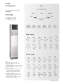
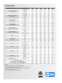
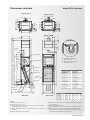
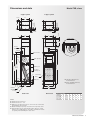
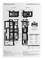
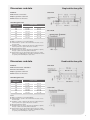
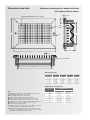
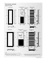
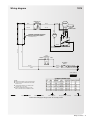
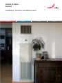
Vertical Hi-Stack Fan Coil Installation, Operation and Maintenance Heating Cooling Fresh Air Clean Air i Airflow arrangements 1 General data 2 Dimensions and data 3 General information 6 Installation9 Wiring diagram 13 Start-up15 Maintenance19 Replacement parts 21 Equipment start-up checklist 22 Troubleshooting26 Warranty33 IMPORTANT: Approved submittal documentation, specific to each project, supersedes the general guidelines contained within this document. Airflow arrangements BACK Riser and supply air discharge designations TOP LEFT Example: BFNN B = Riser location F = Supply air 1 location N = Supply air 2 location N = Outside air location RIGHT O.A. O.A. FRONT B Back F Front L Left R Right T Top N None Single supply LBNN BLNN BFNN RLNN RFNN BRNN LRNN LFNN BTNN LTNN RBNN RTNN Double supply BFLN Notes: Return air always in front of unit. Access to internal components always through front panel. Sight and sound baffles provided as required, ordered separately. Sight and sound baffle not available with top outlet configurations. The above arrangements apply to hideaway and master units only. Slave units and hideaway units without risers have piping connections where pipes are shown in diagrams to the right. Outside air available on left or right side of unit opposite riser side. Available on both sides with back riser location. Optional riser chase available for hideaway units. Contact factory for pricing. RLBN BLRN RFBN LFBN LRBN BLTN BFTN BRTN RLTN RFTN BFRN LFRN RFLN LRTN LBTN LFTN RBTN Airflow arrangements 1 General data Unit size Certified cooling capacity (3 row main coil) Certified cooling capacity (4 row main coil) Heating capacity (3 row main coil) Heating capacity (4 row main coil) Heating capacity (optional 1 row reheat coil) Heating capacity (optional 2 row reheat coil) 03 04 06 08 10 12 Total MBH 12.4 14.3 22.2 25.7 35.0 38.2 Sensible MBH 8.4 9.5 14.8 17.2 24.8 26.1 GPM 2.5 3.0 4.7 5.4 7.4 8.0 PD, ft. of H2O 6.7 9.7 23.8 13.6 24.5 28.3 Total MBH 14.3 17.2 24.3 32.6 44.3 47.0 Sensible MBH 9.6 11.7 16.5 20.6 30.1 32.4 GPM 2.8 3.5 4.9 6.8 9.1 9.7 PD, ft. of H2O 11.1 16.3 30.6 18.3 44.2 49.9 MBH 34.2 43.7 66.1 75.7 105.6 116.3 GPM 3.5 4.5 6.8 7.8 10.8 11.8 PD, ft. of H2O 10.7 16.9 36.8 22.5 42.1 50.4 MBH 36.3 47.3 74.3 83.1 119.5 133.0 GPM 3.7 4.8 7.6 8.5 12.2 13.6 PD, ft. of H2O 15.1 24.8 57.7 32.6 64.3 78.6 MBH 19.9 23.7 31.6 38.6 48.6 52.0 GPM 2.1 2.4 3.2 4.0 4.9 5.3 PD, ft. of H2O 7.5 10.3 17.3 7.1 10.9 12.3 MBH 29.2 36.3 52.1 61.2 80.7 88.8 GPM 3.0 3.7 5.3 6.3 8.3 9.1 PD, ft. of H2O 5.8 8.7 17.3 8.2 13.8 16.5 1280 CFM 320 425 680 700 1120 250 290 450 600 700 850 Low 170 200 330 510 600 630 High 300 420 790 825 970 1230 Medium 255 350 480 515 575 1020 Low 230 290 350 415 400 530 FPI 12 12 12 12 12 12 Face area, ft.2 2.5 2.5 2.5 3.75 3.75 3.75 Coil connections 1/2" Cu 1/2" Cu 1/2" Cu 1/2" Cu 1/2" Cu 1/2" Cu Quantity 1 1 1 1 1 1 Diameter 6.6 6.6 6.6 8.8 8.8 8.8 9.5 CFM, high static (@ 0.2" ESP) Coil High Medium Blower Filter Width 7.0 7.0 7.0 9.5 9.5 Number 1 1 1 1 1 1 Length, in. 30 30 30 30 30 30 18.5 Width, in. 12.5 12.5 12.5 18.5 18.5 Thickness, in. 1 1 1 1 1 1 Height, in. 88 88 88 88 88 88 Cabinet size Length, in. 18 18 18 18 18 18 Width, in. 18 18 18 24 24 24 Inlet, in.2 314 314 314 450 450 450 Outlet, in.2 168 168 168 224 224 224 Base unit shipping weight, lbs. 170 170 170 225 225 225 (4) 2" risers and (1) 1" riser shipping weight, lbs. 185 185 185 245 245 245 (4) 2" risers and (1) 1" riser shipping weight, lbs. 100 100 100 100 100 100 Minimum free area Notes: Airflow under dry conditions. Inlet air 70-80 °F DB. Cooling capacity based on inlet air 80 °F DB, 67 °F WB, 45 °F entering water, 55 °F leaving water, high fan speed. Heating capacity based on inlet air 60 °F DB, 180 °F entering water, 160 °F leaving water, high fan speed. Pressure drop (PD) shown in feet of water. 2 Dimensions and data Model FVH, hideaway 2-pipe system 2-1/2" 1-1/4" F 3" C 4-3/8" CS R D S 1-9/16" 2-9/16" D 4-3/8" R D S E HR HS D CR CS CS CR D HS CR D HS HR HR 2-3/16" 2-3/16" C Swage C F E D G 2-1/2" 1-9/16" 2-9/16" 2-1/2" 1-1/4" 2-1/2" R D S 4-pipe system Control box 2-11/16" 2-1/4" 2-11/16" Motor blower 63-5/8" Heating coil Acceptable riser combinations 3-1/2" 37-1/2" Cooling/ heating coil 5" Throwaway filter Drain pan 18" 13" - 24" Piping range Outside air damper 1-1/4" 5-3/4" 5" 1-3/8" Left: 08-12 blower/motor, viewed from front Above: 03-06 blower/motor, viewed from front Valve package 55-3/16" (Door 53-3/4") 57-1/8" 104" - 115" 88" Front access panel “P” trap B A Side view Notes: All dimensions are in inches All dimensions are +/- 1/4" Wiring from electrical entry point to control enclosure is furnished and installed by others in field Risers available from 3/4" to 2-1/2" diameter with 1/2" or 3/4" thick insulation Riser length is 104"-115" standard Front view Supply and return (insulation) Condensate (insulation) ≤2-1⁄2" (1⁄2") ≤3⁄4" (1⁄2") ≤2" (1⁄2") ≤1" (1⁄2") ≤2" (1⁄2") ≤1-1⁄2" (1⁄2") ≤1-1⁄2" (3⁄4") ≤3⁄4" (1⁄2") ≤1-1⁄4" (3⁄4") ≤1" (1⁄2") ≤1" (3⁄4") ≤1-1⁄4" (1⁄2") ≤1-1⁄4" (3⁄4") ≤3⁄4" (3⁄4") ≤1" (3⁄4") ≤1" (3⁄4") Dimensional data Unit size A B C D E F G 03, 04, 06 18 12-1⁄2 14 12 6 2 2 08, 10, 12 24 18-1⁄2 16 14 7 4 1 Back riser location shown. See arrangement drawings for available unit configurations. Factory mounted risers shown Outside air damper opening is located on left or right side of unit All listed dimensions are approximate and are subject to change without notice. Modifications to the product specifications must be accepted by Zehnder Rittling at its base office. Dimensions and data 3 Dimensions and data Model FVM, master 2-pipe system 2-1/2" CS R D S F 1-9/16" 2-9/16" E D R D S R D S 2-1/2" 4-3/8" 2-1/2" 4-3/8" HR HS D CR CS CS CR D HS CR D HS HR HR 1-9/16" 2-9/16" 2-1/2" 1-1/4" 4-pipe system 2-3/16" 2-3/16" C Swage 3" C G E D F 1-1/4" C Control box 2-11/16" 2-1/4" 2-11/16" Motor blower 37-1/2" Cooling/ heating coil 5" Throwaway filter 3-1/2" Drain pan 13" - 24" Piping range 5-3/4" 1-1/4" 18" Outside air damper “P” trap Side view Notes: All dimensions are in inches All dimensions are +/- 1/4" Wiring from electrical entry point to control enclosure is furnished and installed by others in field Risers available from 3/4" to 2-1/2" diameter with 1/2" or 3/4" thick insulation Riser length is 104"-115" standard 4 63-5/8" Heating coil 5" 1-3/8" Left: 08-12 blower/motor, viewed from front Above: 03-06 blower/motor, viewed from front Valve package 55-3/16" (Door 53-3/4") 57-1/8" 104"- 115" 88" Front access panel Acceptable riser combinations Supply and return (insulation) Condensate (insulation) ≤2-1⁄2" (1⁄2") ≤3⁄4" (1⁄2") ≤2" (1⁄2") ≤1" (1⁄2") ≤2" (1⁄2") ≤1-1⁄2" (1⁄2") ≤1-1⁄2" (3⁄4") ≤3⁄4" (1⁄2") ≤1-1⁄4" (3⁄4") ≤1" (1⁄2") ≤1" (3⁄4") ≤1-1⁄4" (1⁄2") ≤1-1⁄4" (3⁄4") ≤3⁄4" (3⁄4") ≤1" (3⁄4") ≤1" (3⁄4") Dimensional data B Unit size A B C D E F G A 03, 04, 06 18 12-1⁄2 14 12 6 2 2 Front view 08, 10, 12 24 18-1⁄2 16 14 7 4 1 Back riser location shown. See arrangement drawings for available unit configurations. Factory mounted risers shown Outside air damper opening is located on left or right side of unit All listed dimensions are approximate and are subject to change without notice. Modifications to the product specifications must be accepted by Zehnder Rittling at its base office. Dimensions and data Model FVS, slave 2-pipe system 1-1/4" 4-pipe system C 1-9/16" 2-9/16" 2-3/16" 2-3/16" C C F E D G 1-1/4" D 1-9/16" 2-9/16" E F Control box 2-11/16" 2-1/4" 2-11/16" Front access panel 3-1/2" 37-1/2" Heating coil 5" Cooling/ heating coil Throwaway filter Drain pan Left: 08-12 blower/motor, viewed from front Above: 03-06 blower/motor, viewed from front 5-3/4" Outside air damper 1-1/4" 5" 1-3/8" 63-5/8" Valve package 57-1/8" 55-3/16" (Door 53-3/4") 88" Motor blower 18" B A “P” trap Side view Front view Dimensional data Unit size A B C D E F G 03, 04, 06 18 12-1⁄2 14 12 6 2 2 08, 10, 12 24 18-1⁄2 16 14 7 4 1 Notes: All dimensions are in inches All dimensions are +/- 1/4" Wiring from electrical entry point to control enclosure is furnished and installed by others in field Outside air damper opening is located on left or right side of unit All listed dimensions are approximate and are subject to change without notice. Modifications to the product specifications must be accepted by Zehnder Rittling at its base office. Dimensions and data 5 Dimensions and data Model FVA/FVB: Back to back 1-9/16" 2-9/16" C 5/8" Type “X” drywall Support frame 42" C G Support frame E Support frame 2-1/2" 1-1/4" D C Swage F 1-1/4" E D 3" Hr Hs D Cr Cs 2-1/2" F 5/8" Type “X” drywall 4-3/8" 4-3/8" 6" R D S 2-3/8" 4-pipe system 3" 1-9/16" 2-9/16" 2-3/8" 2-pipe system Control box 2-11/16" 2-1/4" Motor blower Front access panel Left: 08-12 blower/motor, viewed from front Above: 03-06 blower/motor, viewed from front 63-5/8" Valve package 57-1/8" 55-3/16" (Door 53-3/4") 104" -115" 88" 2-11/16" Throwaway filter 5" Drain pan Outside air damper 18" 13" - 24" Piping range 1-1/4" 5-3/4" 5" 1-3/8" Cooling/ heating coil 3-1/2" 37 1/2" Heating coil Support frame 5/8" Type “X” drywall “P” trap Side view B A Front view Acceptable riser combinations Supply & Return (Insulation) Condensate (Insulation) ≤2-1⁄2" (1⁄2") ≤3⁄4" (1⁄2") ≤2" (1⁄2") ≤1" (1⁄2") ≤2" (1⁄2") ≤1-1⁄2" (1⁄2") ≤1-1⁄2" (3⁄4") ≤3⁄4" (1⁄2") ≤1-1⁄4" (3⁄4") ≤1" (1⁄2") ≤1" (3⁄4") ≤1-1⁄4" (1⁄2") ≤1-1⁄4" (3⁄4") ≤3⁄4" (3⁄4") ≤1" (3⁄4") ≤1" (3⁄4") Dimensional data Unit Size Notes: All dimensions are in inches All dimensions are +/- 1/4" Wiring from electrical entry point to control enclosure is furnished and installed by others in field Risers available from 3/4" to 2-1/2" diameter with 1/2" or 3/4" thick insulation Riser length is 104"-115" standard 6 C D E F 03, 04, 06 18 12-1⁄2 A B 14 12 6 2 G 2 08, 10, 12 24 18-1⁄2 16 14 7 4 1 Back riser location shown. See arrangement drawings for available unit configurations. Factory mounted risers shown Outside air damper opening is located on left or right side of unit All listed dimensions are approximate and are subject to change without notice. Modifications to the product specifications must be accepted by Zehnder Rittling at its base office. Dimensions and data Single deflection grille Features Aluminum construction Epoxy powder coat finish Dimensions are in inches Side view Standard grille sizes Model size Height x width Single supply Double supply 03 6" x 14" 6" x 14" 04 6" x 14" 6" x 14" 06 12" x 14" 6" x 14" 08 14" x 16" 7" x 16" 10 14" x 16" 14" x 16" 12 14" x 16" 14" x 16" Face view Notes: Grilles are shipped loose for field installation Standard finish is “powder coated” and will be the same color as the return grille Installation of grille on adjacent unit sides may require furring one side away from unit to prevent interference of frames Mounting hardware included Negligible air pressure drop is experienced, regardless of quanity and type of grille used, leaving airflow unaffected All listed dimensions are approximate and are subject to change without notice. Modifications to the product specifications must be accepted by Zehnder Rittling at its base office. Dimensions and data Double deflection grille Features Aluminum borders and blades Vertical front blades Epoxy powder coat finish Dimensions are in inches Side view Standard grille sizes Model size Height x width Single supply Double supply 03 6" x 14" 6" x 14" 04 6" x 14" 6" x 14" 06 12" x 14" 6" x 14" 08 14" x 16" 7" x 16" 10 14" x 16" 14" x 16" 12 14" x 16" 14" x 16" Face view Notes: Grilles are shipped loose for field installation Standard finish is “powder coated” and will be the same color as the return grille Installation of grille on adjacent unit sides may require furring one side away from unit to prevent interference of frames Mounting hardware included Negligible air pressure drop is experienced, regardless of quanity and type of grille used, leaving airflow unaffected All listed dimensions are approximate and are subject to change without notice. Modifications to the product specifications must be accepted by Zehnder Rittling at its base office. 7 Dimensions and data Aluminum discharge grille, double deflection with opposed blade damper 5/32" Individually adjustable blades on 2/3" spacing 1-1/4" Slide operator C D 5/8" 2-13/16" A 2/3" One piece extruded frame B Dimensional data Grille size H W A B 14" x 16" 13-11/16" 15-11/16" 17-11/16" 17-11/16" 12" x 14" 11-11/16" 13-11/16" 15-11/16" 15-11/16" 7" x 16" 6-11/16" 15-11/16" 17-11/16" 17-11/16" 6" x 14" 5-11/16" 13-11/16" 15-11/16" 15-11/16" Supply grille arrangements Unit size Notes Vertical blades in the front, horizontal blades in the back, both individually adjustable and on 2/3" spacing Opposed blade damper with slide operator Aluminum roll formed blade with semi-airfoil design Pressure fit nylon pivot pins (rattle-free and non-loosening) Aluminum extruded frame with mechanically locked corners Countersunk screw holes complete with painted mounting screws Sealing gasket to prevent streaking on walls or ceiling Durable powdercoat painted finish Negligible air pressure drop is experienced, regardless of quanity and type of grille used, leaving airflow unaffected All listed dimensions are approximate and are subject to change without notice. Modifications to the product specifications must be accepted by Zehnder Rittling at its base office. 8 Height x width Single supply Double supply 03 6" x 14" 6" x 14" 04 6" x 14" 6" x 14" 06 12" x 14" 6" x 14" 08 14" x 16" 7" x 16" 10 14" x 16" 14" x 16" 12 14" x 16" 14" x 16" Dimensions and data Return air grille Standard louver 03-06 Frame 03-06 Optional grille 03-06 Optional ADA thermostat location 4-7/8" 2-11/16" 1/2" 2-1/4" 55-3/16" 53-3/4" 45° 55-11/16" 53-9/16" 53-13/16" 41-1/16" Ø3/16 Mounting hole (typical) 27-7/8" 3/4" 4-7/8" 17-5/16" 8-7/8" 15-13/16" 17-11/16" 16" 1-1/16" 15-13/16" Frame 08-12 Standard louver 08-12 Optional ADA thermostat location 1-1/8" 1-1/16" Optional grille 08-12 4-7/8" 1/2" 2-11/16" 2-1/4" 53-3/4" 45° 55-11/16" 55-3/16" 53-13/16" 53-9/16" Ø3/16 Mounting hole (typical) 41-1/16" 27-7/8" 3/4" 4-7/8" 23-5/16" 21-13/16" 11-7/8" 1-1/8" 23-11/16" 22" 1-1/16" Notes: Frame and return grilles are shipped loose for field installation Optional grille does not come with a frame Contact the factory regarding extended front panels for additional control panel access and/or ADA mounting of thermostats 21-13/16" 1-1/16" All listed dimensions are approximate and are subject to change without notice. Modifications to the product specifications must be accepted by Zehnder Rittling at its base office. Dimensions and data 9 General information Safety considerations This installation and start-up instructions literature is for Vertical Hi-Stack Fan Coil units. Fan coils are hydronic terminal units designed for year-round cooling or cooling/ heating. Your equipment is initially protected under the Zehnder Rittling standard 2-year warranty provided the steps outlined in this manual for initial inspection, installation, periodic maintenance and normal every day operation of the equipment are followed. This manual should be thoroughly reviewed prior to the installation, start-up or maintenance of the equipment. If any questions arise, please contact your local Zehnder Rittling sales representative or the factory before proceeding any further. The installation of Vertical Hi-Stack Fan Coil units and all associated components, parts and accessories which make up the installation, shall be in accordance with the regulations of all authorities having jurisdiction and must conform to all applicable codes. Only trained and qualified service personnel using good judgment and safe practices should install, repair and/or service air conditioning equipment. There are a multitude of options and accessories available with the equipment covered in this manual. For more specific details on the included options and accessories, refer to the order acknowledgment, approved submittals and catalogs. Untrained personnel can perform basic maintenance functions such as cleaning coils and cleaning or replacing filters. All other operations should be performed by trained service personnel. When working on air conditioning equipment, observe precautions in the literature, tags and labels attached to the equipment and all other safety precautions that may apply. Improper installation, adjustment, alteration, service, maintenance, or use can cause explosion, fire, electrical shock or other hazardous conditions which may cause serious personal injury and/or property damage. Consult a qualified installer, service agency, or your sales representative for information or assistance. The equipment must always be properly supported by rigging and lifting equipment. Any temporary supports used during installation or maintenance must be designed to adequately hold the equipment in place until equipment is permanently fastened and set in its final location. All supports must meet applicable local codes and ordinances. 10 All fastening devices must be designed to mechanically hold the assembly in place without the ability to loosen or break away due to system operation or vibration. All power must be disconnected and locked out before any installation or service is performed to avoid electrocution or shock. More than one power source may be supplied to a unit. Power to remote mounted units may not be supplied through the unit. Electric resistance heating elements must be disconnected prior to servicing to avoid burns. Never use bulky or loose fitting clothing when working on any mechanical equipment. Gloves should always be worn for protection against heat, sharp edges and all other possible hazards. Safety glasses should always be worn, especially when drilling, cutting or working with chemicals. Never pressurize equipment beyond specified pressures as shown on unit rating plate. Always pressure test with an inert fluid such as water or dry nitrogen to avoid possible damage or injury in the event of a leak or component failure during testing. Always protect adjacent flammable material when welding or soldering. Use a suitable heat shield material to contain sparks or drops of solder. Have a fire extinguisher readily available. Safety considerations Please follow standard safe practices regarding the handling, installing or servicing of mechanical equipment. Read these instructions thoroughly and follow all warnings or cautions attached to the equipment. Consult local building codes and the National Electrical Code(NEC) for special installation requirements. Understand the signal words: danger, warning and caution. Identifies the most serious hazards which will result in severe personal injury or death. Signifies hazards that could result in personal injury or death. Used to identify unsafe practices, which would result in minor personal injury or product and property damage. The manufacturer assumes no responsibility for personal injury or property damage resulting from improper or unsafe practices during the handling, installation, service or operation of the equipment. The installation of fan coils and all associated components, parts and accessories shall be in accordance with the regulations of all authorities having jurisdiction and must conform to all applicable codes. It is the responsibility of the installing contractor to determine and comply with all applicable codes and regulations. Receiving Upon delivery, examine each unit carefully for shipping damage. Any damage should be reported to the freight carrier and a claim should be filed with them. Ensure the shipping company makes proper notation of any shortages or damage on all copies of the freight bill. Concealed damage not discovered during unloading must be reported to the shipping company within 15 days of receipt of the shipment. All units are shipped F.O.B. factory. Therefore, Zehnder Rittling is not responsible for damage during transit. It is the responsibility of the installing contractor to inspect and verify that the unit shipped was in fact the correct model number, voltage, etc. Any discrepancies should be reported to the local Sales Representative for immediate resolution prior to uncrating and installation. The factory should be notified of any warranty repairs required in writing before any corrective action is taken. The factory must be fully informed of the expected costs before the work is begun. Zehnder Rittling is not responsible for any repairs or alterations made by the purchaser without Zehnder Rittling’s written consent and will not accept any back charges associated with these repairs or alterations. The return of damaged equipment will not be accepted without written authorization from Zehnder Rittling. A unit that has received a written Return Goods Authorization will be inspected by Zehnder Rittling upon receipt. Any damage, missing parts, reworking or re-crating resulting from prior installation will constitute just cause for Zehnder Rittling to issue partial credit. Several components are shipped loose for field installation and to offer added protection during shipment and job site storage. These items may include: thermostats, supply grilles, return air access doors, risers, etc. General information 11 Unpacking and preparation All units are carefully inspected at the factory throughout the entire fabrication and assembly processes under Zehnder Rittling’s stringent quality assurance program. All major components and subassemblies such as motors, blowers, coils, controls, valve packages and paint quality are carefully tested for proper operation, visually inspected and verified for full compliance with factory standards. Operational testing for some customer furnished components such as pneumatic valves and DDC controllers may be a possible exception. Vertical Hi-Stack Fan Coil units are usually shipped on pallets of up to six units. Since equipment is normally moved to each floor on the shipping pallet, units can be palletized by floor at the request of the customer, thereby avoiding field handling of the equipment. Should the number of units per floor not be divisible by six, then one pallet will have units for multiple floors. Each unit is factory tagged according to the customer’s purchase order. This allows the unit, upon removal from the pallet, to be taken directly to its’ assigned space for immediate installation. Units should not be installed at locations other than that designated on the tag. It is the sole responsibility of the customer to provide the protection necessary to prevent vandalism and weather deterioration of the equipment. Under no condition should the units be left unprotected from the elements. The equipment is NOT suitable for outdoor installations. 12 Once the equipment is properly positioned on the job site, cover the unit openings with either a shipping carton, vinyl film, or an equivalent protective covering. Take special care to prevent foreign materials from entering the units in areas where painting, dry walling, or spraying of fireproof material, etc. has not yet been completed as these materials may accumulate in the drain pan or on the motors and blower wheels. Foreign material that accumulates within the units can prevent proper startup, necessitate costly clean-up operations, or result in immediate or premature component failure. Before installing any of the system components, be sure to examine each pipe, fitting and valve, and remove any dirt or foreign material found in or on these components. All manufacturer’s warranties are void if foreign material is allowed to be deposited in the drain pan or on the motor or blower wheels of any unit. DO NOT store or install units in corrosive environments or in locations subject to temperature or humidity extremes (e.g., attics, garages, rooftops, etc.). Corrosive conditions and high temperature or humidity can significantly reduce system performance, reliability and overall service life. Handling and installation While all equipment is designed for durability and fabricated with heavy gauge materials and may present a robust appearance, great care must be taken to assure that no undue force is applied to the coil, piping, drain connection or other delicate components such as control boards during handling. Wherever possible, all units should be maintained in an upright position and must be handled by the cabinet. At no time during handling should the unit be supported or lifted by the risers. Damage to riser pipe or leaking connections resulting from improper handling is not covered under the warranty. Preliminary installation Although Zehnder Rittling does not become involved with the design and selection of support methods and/or components, it should be recognized that unacceptable operating characteristics and/or performance may result from poorly implemented unit support. Lifting or supporting the cabinet only at the top and bottom should be avoided to maintain a straight and square cabinet. When lowering the cabinet into place, take care to properly align the risers so they engage the swage connection on the risers below. Never bend or push risers together to pass through the opening in the floor. Zehnder Rittling assumes no responsibility for personal injury or property damage resulting from improper or unsafe practices during the handling, installation, servicing or operation of equipment. Installation of the Vertical Hi-Stack Fan Coil should begin on the lowest floor and progress upward, floor by floor, to the top. Tip the unit over the riser hole in the building floor. As the unit is righted, align the risers with the unit below. In the case of shipped loose risers, install from the lowest floor to the highest floor. After the risers are field tested for leaks, the Fan Coils can then be installed in any order. Risers are supported, anchored and isolated in the field by others. Field-furnished isolator pads, if required, should be positioned beneath the unit at this time. On certain units, shipping screws or braces for valves should be removed before attaching any drywall to the unit. Be sure to check all labels on the unit to determine which, if any, of these supports need to be removed. General information 13 Installation positioning, fastening and testing Each riser is supplied with a 3-inch swaged portion on the top and sufficient extension at the bottom for an inserted length of approximately 2 inches. This unit-to-unit joint is not intended for full bottoming in the joint. When installing the Vertical Hi-Stack unit to the unit below, the risers should never be pulled down to engage in the swage connection. This is already accounted for in the riser lengths and allows for variations in floor-to-floor dimensions and correct riser positioning. Some jobs require that the unit risers be supplemented with “between-the-floor” extensions. These pieces should be assembled into position at this time. “Between-the-floor” extensions may be field or factory supplied. If the latter, insulation is also provided. Once the units are positioned with the risers centered in the pipe chase, each unit should be positioned perfectly vertical (plumb) in two planes and anchored to the building structure. All assemblies must be adequately secured during lifting and rigging until equipment is permanently fastened and set in its final location. All temporary and permanent supports must be capable of safely supporting the equipment’s weight along with any additional live or dead loads that may occur. All supports must be designed to meet applicable local codes. All fastening devices must be designed to mechanically lock the equipment in place without the possibility of loosening or breaking away due to system operation or vibration. It is imperative that the unit be properly leveled to assure condensate drainage and proper coil operation. Once all units on a riser are anchored, unit-to-unit riser joints may be made as follows: Each branch run out in the coil section must be centered in the expansion slot in the side or back panel prior to joining risers. Ensure that clamps on drain pan P-trap are secured and have not loosened during shipment or installation. Make sure the branch run out is pitched slightly downward inside the unit so condensate, if formed, will run back into the condensate pan and not out toward the riser. Any water damage caused by not following this procedure is not covered under the warranty. 14 Each riser joint must be in vertical alignment, with a minimum of 1" penetration (although 2" is preferable and allowed for) into each swaged joint. This condition will be met if floor-to-floor dimension is as specified and if each branch run out is properly centered. Riser joints must be made with phos-copper, silfos, or other high temperature alloys. Soft solders (50-50, 60-40, 85-15) or other low temperature lead alloys are not suitable for this application. Use flame and heat protection barriers where needed during soldering or brazing process to protect adjacent flammable materials. Care should be taken to assure that no valve package components are subjected to high temperature, which may damage seals or gaskets. If the valve package connection at the coil is made with a union, the coil side of the union must be prevented from twisting during tightening to prevent damage to the coil tubing. Over-tightening must be avoided to prevent distorting the union seal surface and destorying the union, ultimately causing a leak. Secure the union nut hand-tight and then tighten no more than an additional 1/4 turn. Wide variations in floor-to-floor dimensions may necessitate cutting off or extending individual risers. Such modifications are the full responsibility of the installing contractor. The risers must not be rigidly fastened within each unit, but must be free to move within the pipe chase with normal vertical expansion and contraction movements. The installing contractor must anchor the built-in risers at some point to the building structure. The unit design will accommodate up to a 1" expansion and contraction (2" total movement). The installing contractor must provide and install additional expansion compensation devices in each riser. Venting of risers must be provided by installing contractors. Once all field riser joints are completed and the riser assembly is properly anchored, a hydrostatic test for leaks should be made, but test pressure must not exceed 250 psi, measured at the bottom of the riser. At this time, prior to insulating and furring in of any Installation positioning, fastening and testing risers or piping connections, all coils should be vented, and the interior unit piping checked for visible signs of leakage due to possible shipping damage or mishandling. The coil manual air vent is accessible through the return-air opening. After the test, insulate all risers continuously from top to bottom, if not provided by factory. All unit piping and water coils must be protected from freezing after filling with water. All leaks should be repaired before proceeding with installation. All field-furnished and installed riser insulation must have a vapor barrier cover, or be closed-cell foam insulated. All joints should be properly sealed (taped or glued) so no air can pass through to the cold riser pipe. Any water damage caused by not following this procedure is not covered under the warranty. To assure compliance with existing building codes, the installing contractor must restore the original fire resistance rating of the structure by sealing the access space around the risers with material having the same fire ratings as structure. Applicable local installation codes may limit this unit to installation in single-story residences only. Any fireproofing requirements where risers or piping penetrate the floors or walls are the responsibility of the installing contractor. This work should only be done after all pressure testing is complete. Whatever method is used for fireproofing must be able to accommodate pipe expansion and contraction. The piping must be protected from abrasion and/or chemical attack. Pipe insulation must be maintained to prevent condensation and should be protected from damage at the joint between the insulation and fireproofing material. The riser connection joints should be hydrostatically tested for leaks before furring in the unit. Pressure of water column alone is approximately 0.43 psi per foot; i.e., 43 psi for each 100 feet. DO NOT EXCEED 250 PSI or that which the supplied components were designed. Installation 15 Ductwork connections All ductwork and or supply and return grilles should be installed in accordance with the project plans and specifications. If not included on the unit or furnished from the factory, supply and return grilles should be provided as recommended in the product catalog. All units must be installed in non-combustible and nonhazardous areas. Some models are designed to be connected to ductwork with a minimum amount of external static pressure. These units may be damaged by operation without the proper ductwork connected. Consult the approved submittals and the product catalog for unit external static pressure limitations. Units provided with outside air should have some form of low temperature protection to prevent coil(s) from freezing. This protection may be a lowtemperature thermostat to close the outside air damper, a preheat coil to temper the outside air before it reaches the unit, or any other protective method. It should be noted that none of these methods will adequately protect a coil in the event of power failure. The safest method of freeze protection is to use glycol in the proper percent solution for the coldest expected air temperature. 16 Flexible duct connections should be used on all air handling equipment to minimize vibration transmissions. Insulation and ductwork should be installed to allow servicing of equipment. It is recommended to have sight/ sound baffles installed on dual, opposite side, discharge units with the exception of top discharge. It is also recommended to have at least one discharge grille with damper to aid in air balancing. Dual discharge units with top discharge require a field supplied and installed damper in the top discharge duct. Zehnder Rittling assumes no responsibility for undesirable system operation due to improper design, equipment or component selection, and/or installation of base unit, ductwork, grilles and other related components. Special application Operation of the unit with fieldfabricated outside air provision, or operation in coastal areas of high humidity may make it necessary to add insulation and/or a suitable vapor barrier between the drywall material and the air handling compartment. Such recommendations will be made by the factory upon request. Wiring diagram 120V L T1 M H MOTOR QUICK CONNECT SEE MOTOR CHART FOR WIRE COLORS YELLOW BLUE YELLOW BLOWER MOTOR WHITE RED CONTROL PACKAGE LOCATION D DAMPER MOTOR F BLUE IF A CONTROL PACKAGE IS ORDERED, REFER TO CORRESPONDING SCHEMATIC FOR WIRING LAYOUT E BLACK L1 WHITE T2 BLUE L2 HEATER MANUAL MOTOR STARTER WHITE *BROWN 3-SPEED SWITCH YEL GFCI RECEPTACLE HOT 120V L2 NEUTRAL WHITE WHITE *BROWN TERMINATED IF NO DAMPER MOTOR 120V L1 HOT LINE HOT WHITE LOAD DISCONNECT SWITCH YELLOW WHITE YELLOW L1 HOT (YELLOW) WHITE 120VAC L2 NEUTRAL (WHTIE) A B SPARE TERMINALS C G H I NOTES: ■ THERMOSTAT SHIPPED LOOSE IF WALL MOUNTED. ■ CONTROL VALVE AND CHANGEOVER SWITCH ARE SHIPPED LOOSE. ■ COMPLETE THE WIRING IN ACCORDANCE WITH NATIONAL AND LOCAL CODES. ■ IF REMOTE TEMPERATURE SENSOR IS USED, WIRE TO THERMOSTAT TB1, TERMINALS 1 AND 2. Field wired Factory wired 18AWG Factory wired 16AWG Wire connection Factory wire, not connected Wire termination CAUTION: Not following proper wiring procedure can cause injury or death Wiring schematics 17 Wiring schematic 208V/240V/277V BLACK BLACK BLACK BLOWER MOTOR L H MOTOR QUICK CONNECT SEE WIRE CHART FOR WIRE COLORS RED D CONTROL PACKAGE LOCATION E F BLACK BLACK BLUE BLACK M IF A CONTROL PACKAGE IS ORDERED, REFER TO CORRESPONDING SCHEMATIC FOR WIRING LAYOUT *BROWN 3-SPEED SWITCH BLACK BLACK *BROWN TERMINATED DISCONNECT SWITCH BLACK BLACK L1 HOT (BLACK) BLACK BLACK L2 HOT (BLACK) A 208 / 240 / 277VAC B C G H I SPARE TERMINALS NOTES: ■ THERMOSTAT SHIPPED LOOSE IF WALL MOUNTED. ■ CONTROL VALVE AND CHANGEOVER SWITCH ARE SHIPPED LOOSE. ■ COMPLETE THE WIRING IN ACCORDANCE WITH NATIONAL AND LOCAL CODES. ■ IF REMOTE TEMPERATURE SENSOR IS USED, WIRE TO THERMOSTAT TB1, TERMINALS 1 AND 2. Field wired Factory wired 18AWG Factory wired 16AWG Wire connection Factory wire, not connected CAUTION: Not following proper wiring procedure can cause injury or death 18 Wire termination Electrical connections The electrical service to the unit should be compared to the unit nameplate to verify compatibility. The type and sizing of all wiring and other electrical components such as circuit breakers, disconnect switches, etc. should be determined by the individual job requirements and should not be based on the size and/or type of connection(s) provided on the equipment. Verify the electrical conductor size is suitable for the distance to the equipment connection and will support the equipment electrical load. All installations should be made in compliance with all governing codes and ordinances. Compliance with all codes is the responsibility of the installing contractor. The unit serial tag lists the unit electrical characteristics such as the required supply voltage, motor and heater amperage and required circuit ampacities. The unit wiring diagram shows all unit and field wiring. The installer must be familiar with the wiring diagram before beginning any wiring as the wiring can change from project to project. All field wiring connecting to this type of unit must be 105 °F rated copper conductor and should be in accordance with the National Electrical Code and any applicable local codes. Branch circuit fusing and electrical disconnect means (if required) must be furnished and installed by others. All unitmounted control components and electrical heater elements (when furnished) are factory wired to the unit junction control box located in the center of the unit. Remote-mounted control components are shipped loose for field installation and wiring. All wiring connections should be checked prior to start-up to ensure connections have not come loose during shipment or installation. The electrical components, located in the upper portion of the unit, facilitate field wiring. The applicable wiring diagram for the unit ships with each unit and must be strictly followed. See unit wiring diagram, provided with unit, for proper voltage and for proper control packages if used. Field power supply wiring should be through knockouts supplied in the side and/or top of the unit. Electrical shock can cause personal injury or death. When installing or servicing system, always turn off main power to system. There may be more than one disconnect switch. Thermostat “OFF” should not be used for disconnect purposes. Only qualified personnel should perform service and installation. Zehnder Rittling assumes no responsibility for any damages and/or injuries from improper field installation and/or wiring. Electrical 19 Enclosing unit All wall framing is the responsibility of others. Normally the units are enclosed in the field-furnished drywall enclosure. The enclosure can be furred out from the unit with studs or the drywall can be attached directly to the sheetmetal cabinet. For maximum sound attenuation, units should be furred out and insulated. If the riser pipes and electrical conduit face the room interior, then an enclosure must be furred out from the unit to provide proper clearance. If the drywall is attached directly to the sheet metal cabinet, use sheet metal low-profile pan-head or drywall screws, no longer than is required to provide proper grip to secure drywall to the sheet metal cabinet. The front of the unit is designed to have drywall flush against the front of the sheet metal cabinet. Either 1⁄2" or 5⁄8" drywall may be used. Be sure to keep drywall dust out of the unit. Drywall dust is hard on motors, and coil efficiency is reduced if drywall dust is allowed to collect on the coil fins. The manufacturer will not be responsible for damaged components due to drywall dust. Do not apply sheet metal screws or nails where they are subject to penetrating the coil, riser pipes, electrical junction boxes, and raceways or where they may impede the removal of internal components. 20 Extreme care is necessary when driving screws in the vicinity of the control box, heat exchange coils and drain pan to prevent electrical shorts and water leaks. The drywall material should not be screwed to either the drain pan edges or to the control-box enclosure. This unit is not intended for direct attachment of wood, chipboard, or similar paneling. All wall finishes must be preceded with drywall. When cutting out supply and return holes for grilles, be sure to clean all drywall dust from coils, drain pans, and blower discharge plenum. After drywall is in place and rooms are prepared for final wall treatment, the supply and return air openings and control component opening should be securely covered to prevent introduction of foreign material. If the wall texture and/or color are to be sprayed, cover the coil, fan, or other unit parts. Unit warranties are voided if paint or foreign materials of any kind are present on coil, fan, piping, wiring, or other internal components. A return air grille/access door and discharge grille (if ordered) are typically furnished with each unit. These items are usually shipped at time of finish to the contractor’s specified destination. The units should not be operated at anytime without complete enclosure, supply grille, return air grille, and filter in place. Operation in any other condition could result in motor overloading or burnout, clogging of coil surface, fan blade damage, or all of the above. Prior to installation of the return grille, the following final checks should be made: 1. Rotate the fan wheel by hand to ensure that it is free and does not rub the housing. Rough handling during shipment may have caused the wheel to shift. Adjust, if necessary. 2. Check to see that the service valves are opened and that the motorized control valve (if supplied) is set for automatic operation, if of such type. 3. Vent all air from the coil and related piping. 4. Check the drain line to see that it is not clogged and that it is properly positioned with a downward pitch and secured. Ensure that all hose clamps are properly connected and tightened down. These connections can come loose during shipment and/or installation. 5. If the unit is equipped with a combination stop and balance valve in the return line, the proper flow should be set at this time. Back-to-back (FVA/FVB) installation The installation instructions included in this manual are provided to meet the requirements of UL1479. Some jurisdictions may require additional or different installation methods; therefore, consult with the authority having jurisdiction for specific differences. For these cases, the requirements defined by the authority having jurisdiction will take precedence over the documents contained herein. Riser chase plate FVA FVB 2" x 4" wall stud A Wood screws A Figure 2: Recess detail The mounting lines for the drywall channel and wall studs should be laid out on the floor and ceiling (see Figure 1:A). 5/8" Type X drywall, field supplied Tracking may be installed now or after the unit is set. Position the back-to-back Fan Coil assembly between two rooms with the unit drywall separation spotted over the wall control lines. Check unit tagging against mechanical drawings to ensure proper location. If not already installed, install the floor and ceiling tracks up to and over the back-to-back Fan Coil unit. Channels up to the unit sides at riser chase plate and ceiling channels over the unit floor assembly, leaving space for the riser penetrations. Next, position the vertical studs and fasten into each of the stud pockets formed into the riser chase plates (see Figure 1:B and Figure 3). Spacing of the vertical studs should be done in accordance with local, state and national codes while meeting project specifications. A. Drywall channel and stud mounting lines B. Install wall stud into recess formed by rise chase plate Wall studs E. Install drywall to sides of unit with optional cut outs for supply, outside air and thermostat F. Install drywall to face of unit with optional cut outs for supply, return and thermostat FVA C. Install studs from top of unit to ceiling (4 corners) D. Install drywall to walls FVB See detail 5/8" Type X drywall, factory supplied The wall studs may be mechanically fastened to the back-to-back Fan Coil within the riser chase plate recess. Install studs from top of unit to ceiling at all four corners (see Figure 1:C). Care should be taken, however, not to penetrate the supply or return water risers or internal piping. Anchor unit to floor through bottom of unit. 1/2" typ. Space as needed Given the levelness of the floor and/ or the Fan Coil assembly, some Figure 3: shimmming may be necessary to Cross section A make the unit square to floor and ceiling. Make any remaining electrical and plumbing connections. Assemble the specified wall construction up to and over the top of the Fan Coil unit. With the fire-wall separation being complete (see Figure 1:D and Figure 2), the drywall skin on the surface of the individual Fan Coils can be applied (see Figure 1:E). Drywall can be applied directly to the surface, or, if necessary, studding may be installed on the corners for vertical control. For ease of installation of the access panel, apply drywall on the return air side directly to the surface of the unit (see Figure 1:F). When applying the drywall directly to the unit cabinet, it may be necessary to shim in some areas to achieve the desired finished wall surface. After all drywalling and painting is complete, install thermostats, supply air grilles and return air panels. Figure 1: Installation Installation 21 Start-up 22 Before beginning any startup, the start-up personnel should take the time to familiarize themselves with the unit, options, accessories and control sequence to fully understand how the unit should operate properly under normal conditions. All personnel should have a good working knowledge of general start-up procedures. After installation and prior to start-up, be sure filter is clean and free of any construction dirt, etc. If not, the filter should be replaced. Failure to do so could result in damage to the equipment or building while voiding all manufacturer’s warranties. All internal doors and walls should be in place. In some cases, the internal decorations and furniture may influence overall system performance. The entire building should be as complete as possible before beginning any system balancing. if the unit is installed during the winter months, care must be taken so that the unit is not subjected to freezing temperatures while filled with water during construction. Coils damaged due to freeze-ups are not covered by the warranty. The building must be completely finished including doors, windows and insulation before system start-up and balancing. A final visual inspection of equipment should be done before commencing with startup. This includes checking for debris, loose wires at terminal block connections and quick connects, free blower wheel operation, leaks, proper drain connections, loose or missing access panels, clean filters, etc. Except as required during startup and balancing, no fan coils should be operated without all the proper ductwork attached, supply and return grilles in place and all the access doors and panels secured in place. Failure to do so could result in damage to the equipment or building and furnishings and will void the manufacturer’s warranty. Water system Prior to water system start-up and balancing, the chilled and hot water systems should be flushed to clean out dirt and debris which may have collected in the piping during construction. All unit service valves should be in the closed position during this procedure to prevent debris from entering metering devices and coils. Strainers are recommended to help protect against debris entering units during normal operation. During system filling, air venting from the unit is accomplished by the use of the standard, manual air vent or the optional automatic air vent that is installed at the top of each coil’s header. Manual air vents are capped Schrader valves. To vent the air from the coil, unscrew the cap, turn the cap over and insert the pointed Water treatment Proper water treatment is a specialized industry and therefore it is recommended to consult an expert in this field to analyze the water for compliance with the water quality parameters listed below and to specify the appropriate water treatment program. The expert may recommend rust inhibitors, scaling preventative, antimicrobial growth agents or algae preventatives. Anti-freeze solutions, glycols, may also be used to lower the freezing point. All Zehnder Rittling water coils are constructed of copper tubes and headers while multiple brass and bronze alloys may be present in the valve packages. It is the end user’s responsibility to ensure that any of the water delivery components are compatible with the treated water. end of the cap into the vent to depress the valve until all of the air has been vented from the coil. When water begins to escape from the vent, release the valve and replace the cap. Automatic air vents may be unscrewed one turn counterclockwise to speed up the initial venting but should be screwed in for automatic venting during normal operation. The air vents provided are not intended to replace the main system air vents and may not release air trapped in other parts of the system. Inspect the entire system for potential air traps and independently vent those areas as required. In addition, some systems may require repeated venting over time to fully eliminate air in the system. Failure to provide proper water quality will void the fan coil unit’s warranty. Water content Required concentration Sulphate < 200 ppm pH 7.0 – 8.5 Chlorides < 200 ppm Nitrate < 100 ppm Iron < 4.5 mg/L Ammonia < 2.0 mg/L Manganese < 0.1 mg/L Dissolved solids < 1000 mg/L Calcium carbonate hardness 300 – 500 ppm Calcium carbonate alkalinity 300 – 500 ppm Particulate quantity < 10 ppm Particulate size 800 micron max Start-up 23 Water system balancing A complete knowledge of the hydronic system, including its components and controls, is essential to proper water system balancing and should only be completed by a qualified expert. The system must be complete, and all components must be in operating condition before beginning the water system balancing procedures. Each hydronic system has different operating conditions depending on the devices and controls installed for the particular application. The actual balancing technique may vary from one system to another. Air system balancing 24 All ductwork must be complete and connected and all grilles, panels and filters installed before the start of balancing. System balancing is to be conducted by a qualified balance specialist. Non-ducted units do not require balancing except to select fan speeds. Ensure that the units are not obstructed by window treatments, drapes or furniture. After the proper system operation is established, the appropriate operating conditions such as water temperatures, flow rates and pressure drops should be recorded for future reference. Before and during water system balancing, conditions may exist due to incorrect system pressures which may result in noticeable water noise or undesired valve operation. After the entire system is balanced, these conditions will not exist on properly designed systems. If any of these conditions persist, recheck the system for air that may not have been properly vented during start-up. After proper system operation is established, the actual unit air delivery and the actual fan motor amperage draw for each unit should be measured and recorded for future reference. EC Motor If the unit is equipped with an EC motor, additional steps may be required during the air balancing process. Review project submittals or order acknowledgment to determine what type of EC motor control is provided. Alternatively, match the control board to the illustrations. The unit has been factory configured to produce the same airflow as the standard PSC motor on all speeds when using the 3-speed control card and a maximum of 10% higher than the high speed setting when using the 0-10 VDC control card. If these settings are acceptable, then no further configuring is required. The control box needs to be powered while adjustments are made. Line voltage components are concealed within a covered junction box. However, the installer should take all necessary precautions to avoid contact with live voltage wires. Controls operation 3-speed control card 0-10 VDC control card The unit has been factory configured to produce the same airflow as the standard PSC motor on all speeds when using the 3-speed control card with a maximum of 10% higher than the high speed setting available on most units during readjustment. If these settings are acceptable, then no further configuring is required. The 0-10 VDC control card is not configured at the factory and needs to be used in conjunction with a field installed/ provided thermostat and/or DDC controller. If alternative airflows are desired, use board mounted potentiometers, marked as FL01, FL02, FL03, to adjust the airflow associated with each input. Each output can be adjusted from 0 to 100% of the motor’s factory programmed operating range using an instrument screwdriver. Insert the screwdriver into the white center of the potentiometer and turn clockwise for an increase in airflow or counterclockwise for a decrease in airflow. Before proper control operation can be verified, all other systems must be operating properly. The correct water and air temperatures must be present to determine if the control function is operating to design. Some controls and features are designed to not operate under certain conditions. For example, a 2-pipe cooling/heating system with auxiliary electric heat, the electric heat will not energize when hot water is present. A wide range of controls, electrical options and accessories may be used with the units covered in this manual. Review the approved project submittals or order acknowledgment for detailed information regarding each individual unit and its controls. Since controls may vary from one unit to another, care should be taken to identify the controls being used with each individual unit and its proper control sequence. Start-up 25 Maintenance General Each unit on a project will have its own unique operating environment and conditions which dictate a maintenance schedule for that unit that may be different from other equipment on the project. A formal regular maintenance schedule and an individual unit log should be established and maintained. Following this schedule will help maximize the performance and service life of each unit on the project. The safety considerations listed in the front of this manual should be followed during any service and maintenance operations. For more detailed service information consult your Sales Representative or the factory. Disconnect power supply from the unit before servicing. ■■ Filter Since the Vertical Hi-Stack Fan Coil is a draw-through coil type, filter must be changed or cleaned a minimum of four times a year. Under certain operating conditions, it may be necessary to change or clean the filters more frequently to obtain maximum unit performance. Brushing should be followed by cleaning with a vacuum cleaner. Compressed air can also be used by blowing air through the coil fins from the leaving air side, again followed by vacuuming. If fins are damaged during the cleaning process, a 12 fins per inch fin comb can be used to straighten the fins. For a deeper cleaning, spray the finned surface with a mild alkali cleaning solution and rinse thoroughly. Failure to maintain a clean coil surface will result in reduced airflow, reduced performance and increased power consumption. Clean the coil at every inspection. Units provided with the proper type of air filters, replaced regularly, will require less frequent coil cleaning. Before performing service at or near any heating coil, piping or valve, disconnect all power, close all isolation valves and allow the equipment to cool. Drain ■■ Once yearly, preferably at the start of the cooling season, the drain pan should be checked and cleaned if necessary. A flexible probe for 3/4-inch pipe may be used to clear any obstruction from the line, or the drain tube may be removed through the lower area of the return-air opening, should more thorough cleaning be needed. Coil ■■ Coils may be cleaned by removing the motor/blower assembly and air filter, providing access to the air entry side of the coil. Brush the entire finned surface with a soft bristled brush, brushing parallel to the fins, taking care not to damage the fins. 26 off plate of each unit for that unit’s individual operating characteristics. All motors have permanently lubricated bearings so no further field lubrication is ever required. The unit motor/blower is directdrive assembly. Remove the air block-off plate to gain access to the motor/blower assembly. The entire motor/blower assembly can be removed from its track through the returnair grille for field servicing by removing a single screw and quick connect. Disconnect all remote electric power supplies before servicing as motors can start automatically. Dirt and dust should not be allowed to accumulate on the blower wheel or housing. Failure to keep this clean may result in an unbalanced wheel condition which can lead to a damaged blower wheel or motor. The wheel and housing may be cleaned periodically using a brush and vacuum cleaner, taking care not to dislodge the factory applied balancing weights on the blower wheel blades. Clean the blower at every inspection. Any blower or motor that is not properly maintained will not be covered under the manufacturer’s warranty. ■■ Electric heating element ■■ Motor/blower assembly The type of fan operation is determined by the control components and their method of wiring. This may vary from unit to unit. Refer to the wiring diagram located in a zip-lock plastic bag on the air block- Finned tubular type heaters generally require no normal periodic maintenance when unit air filters are changed properly. The operation and service life may be affected by other conditions and equipment in the system. The two most important Maintenance operating conditions for an electric heater are proper airflow and proper supply voltage. High supply voltage and/or poorly distributed or insufficient airflow over the heater will result in the element overheating. This condition may result in the heater cycling on the primary automatic high limit thermal cutout. If the temperature becomes too high, the secondary high limit thermal cutout may be activated, breaking the circuit and leaving the unit non-operational. The primary automatic thermal cutout will reset automatically after the heater has cooled down, allowing the unit to run again without intervening. The secondary thermal cutout is a safety device only, is not intended for continuous operation and will need to be replaced before the unit will operate again. With proper unit application and operation, the primary high limit thermal cutout will not operate. This device only operates when there is a problem and ANY condition that causes the high limit cutout to operate MUST be corrected immediately. High supply voltage also causes excessive amperage draw and may trip the circuit breaker or blow the fuses on the incoming power supply. After proper airflow and supply power are verified, regular filter maintenance is important to provide clean air over the heater. A dirty filter will inhibit the proper airflow, leading to high temperature situations. Improper filtration will also lead to dirt being deposited on the heating element, causing hot spots and eventual element burn through. These hot spots will generally not be enough to cause the high limit switches to trip and may not be evident until the element actually fails. Dirt deposited on the element will also cause unwanted odors in the air-conditioned space as the foreign material is burned off. ■■ Electrical wiring & controls The electrical operation of each unit is determined by the components and wiring of the unit. This may vary from unit to unit. Refer to the wiring diagram located in a zip-lock plastic bag on the air block-off plate of each unit for the actual type and number of controls provided on each unit. The integrity of all electrical connections should be verified at least twice during the first year of operation. Afterwards, all controls should be inspected regularly for proper operation. Some components may experience erratic operation or failure due to age. Thermostats may become clogged with dust and lint, and should be periodically inspected and cleaned to provide reliable operation. When replacing any electrical components such as fuses, contactors, relays or transformers, use only the exact type, size and voltage component as furnished from the factory. Any deviation from this could result in personnel injury or damage to the unit. This will also void the manufacturer’s warranty. All repair work should be done in such a way as to maintain the equipment in compliance with governing local and national codes, ordinances and safety testing agency listings. ■■ Valves and piping No formal maintenance is required on the valve package components other than a visual inspection for possible leaks during normal periodic unit maintenance. Strainers, when included, should be checked regularly for buildup and rinsed as needed. In the event that a valve should need replacement, the same precautions taken during the initial installation to protect the valve package from excessive heat should be implemented during replacement ■■ Throwaway filters These types of filters should be replaced on a regular basis. The time interval between replacement is dependent upon the environment in which the unit is operating and should be set established based on regular inspection of the filter. Record the time interval in the maintenance log for future reference. Refer to the product catalog for the recommended filter size. If the replacement filters are not purchased from the factory, the same type and size filters should be obtained. MERV9 or higher pleated media or extended surface filters should not be used without consent from the factory due to the high air pressure drops associated with these types of filters, negatively affecting unit performance. ■■ Cleanable filters These types of filters should be inspected and cleaned on a regular basis, similar to the maintenance schedule Maintenance 27 Maintenance used for throwaway filters. The time interval between cleaning is dependent upon the environment in which the unit is operating and should be set established based on regular inspection of the filter. Record the time interval in the maintenance log for future reference. Unlike throwaway filters, cleanable filters may be cleaned and reinstalled in the unit instead of being disposed of when dirty. The cleanable filters may be washed in hot, soapy water and then set aside to dry before recharging and reinstalling. Before replacing the filter, it should be recharged with some type of entrapment film Replacement parts such as “Film-Car recharging Oil.” The filter should be sprayed on both sides or submerged in the film to assure complete coverage. The filter should not be soaked in the film but should be quickly dunked and removed, allowing the excess to drain off of the surface before reinstalling in the unit. It should be noted that cleanable filters tend to have less air pressure drop than throwaway filters. ■■ Drain The drain pan and drain should be checked during initial start-up and at the beginning of each cooling season to ensure that the pan, drain, trap and line are all securely connected and clear. If clogged, steps should be taken to clear the Periodic checks of the drain should be made during the cooling season to maintain a free-flowing condensate. Should the growth of algae and/or bacteria be a concern, consult an air-conditioning and refrigeration supply company familiar with local conditions for chemicals or other solutions available to control these substances. Factory replacement parts should be used wherever possible to maintain unit performance, it’s normal operating characteristics and its safety testing agency listings. When ordering parts, the following information should be supplied to ensure proper part identification: ■■ Complete unit model number Replacement parts may be purchased through the local Zehnder Rittling Sales Representative. ■■ Complete part description Contact the local Sales representative or factory before attempting any unit modifications. Any modifications not authorized by the factory could result in personnel injury, damage to the unit, and will void the manufacturer’s warranty. 28 foreign debris to allow proper flow of condensate. Failure to strictly follow this instruction, will void the manufacturer’s warranty and the manufacturer will not be responsible for any consequential damages due to water. ■■ Unit serial number including any identifying numbers on the part On warranty replacements, it is often necessary to return the faulty component to receive credit. Contact the local Sales Representative who will get authorization from the factory including an RGA (Returned Goods Authorization) to be used when sending components back for inspection. Any returned components sent back to the factory without the proper RGA attached will cancel any outstanding credit. Troubleshooting Symptom Unit not operating Unit blows fuse when power is applied to unit Fan doesn’t operate Possible cause Corrective action No power to unit. Apply proper power to unit. Incorrect power to unit. Apply correct power to unit and check for damaged components and/or blown fuses, if furnished. Power distribution panel switch or circuit breaker in “OFF” position. Unit toggle disconnect switch in “OFF” position. Fan switch or thermostat system switch in “OFF” position. Blown or defective unit main fuse, if furnished. Defective toggle, fan or thermostat system switch. Turn power distribution panels switch or circuit breaker to “ON” position. Turn unit toggle disconnect switch to “ON” position. Turn fan switch or thermostat system switch to “ON” position. Check for possible defective component or improper wiring and replace fuse. Momentarily jumper suspected component to simulate closed contacts and achieve unit operation. Replace defective device with known good part. Loose or improper wiring from power distribution and/ or remote mounted control devices. Verify all wiring connections and terminations, and verify proper wiring of all incoming power devices and remote mounted controls. Level switch activated, drain pan clogged Remove debris from drain pan, unclog pan, unclog drain and emtpy. Defective or improperly wired component. Using a battery powered continuity tester, check for shorted or grounded components starting at incoming power. Note position of all controls during various component checks. Caution: some voltages have isolated common which may not show a short to chassis ground. Be sure to isolate each control to eliminate faulty reading through a parallel wired component. Thermostat system switch in “OFF” position. Turn thermostat system switch to “ON” position. Remote “start/stop” switch in “OFF” position. Turn remote “start/stop” switch to “ON” position. Loose or improper wiring from fan switch or thermostat to unit. Verify all wiring connections and terminations, and verify proper wiring of all control devices. Loose or improper wiring from remote “start/stop” switch to unit “start/stop” relay. Verify all wiring connections and terminations, and verify proper wiring of remote “start/stop” switch. Defective “start/stop” relay. Momentarily jumper “start/stop” relay to simulate proper relay operation. Replace defective “start/stop” relay. Defective fan motor. Verify proper fan switch operation and replace defective fan motor. Troubleshooting 29 Troubleshooting Symptom Possible cause Incorrect power applied to unit. Fan motor hums Defective motor capacitor. and/or gets hot, but Defective fan motor. operates at reduced speed or not Blower wheel stuck in housing. at all Foreign object in blower wheel. Fan operates but vibrates Fan operates but blower wheel rubs housing Fan operates but air delivery is low Corrective action Apply correct power to unit. Replace with known good capacitor. Replace defective motor. Reposition blower wheel for proper alignment in housing, or replace if damaged. Remove foreign object and replace blower wheel if damaged. Blower wheel dirty. Remove and clean blower wheel taking care not to remove or reposition balance weights. Blower wheel bent. Replace blower wheel. Blower wheel out of balance. Replace blower wheel. Foreign object in blower wheel. Remove foreign object and replace blower wheel, if damaged. Loose motor mount screws. Verify proper motor and blower wheel position, tighten motor mount and set screws. Broken motor mount frame or mounting screws. Replace motor or mounting screws. Bent blower wheel. Replace blower wheel. Blower wheel not positioned properly on motor shaft. Incorrect fan speed has been selected. Check for damage to blower wheel. Reposition blower wheel on motor shaft or replace as required. Dirty air filter. Replace air filter. Dirty coil. Clean coil. Obstruction in ductwork. Actual E.S.P. higher than design. No chilled/hot water flow in system. Unit isolation valves closed. Re-select proper fan speed as required. Check for improperly positioned balancing or fire dampers. Check for fallen duct liner. Repair as required. Check that supply grilles are open. Check installation for proper supply and/or return grilles, and compliance with plans and specifications. Establish chilled/hot water flow in system as designed. Open unit isolation valves. Debris in water piping blocking Locate and clear debris from water piping as required. flow. Plugged strainer. Fan operates but no cooling/heating (hydronic units) Riser or main flushing loop open. Loose or improper wiring from thermostat to control valve. Close flushing loop valve as required. Defective control valve actuator. Verify all wiring connections and terminations, and verify proper wiring of thermostat. Momentarily jumper thermostat contacts to simulate proper operation. Replace thermostat as required. Manually place control valve in “open” position using lever on actuator housing. Replace actuator as required. Improper aquastat operation. Verify proper aquastat position and operation. Replace as required. Defective thermostat. 30 Clean or remove strainer screen as required. Symptom Possible cause No power to electric heating circuit on units with dual point power. Loose or improper wiring from thermostat to electric heating contactor. Loose or improper wiring of electric heating element. Defective electric heating contactor. Tripped or defective primary Fan operates but no heating (electric high limit switch. heating units) Tripped secondary high limit switch. Defective thermostat. Defective electric heating element. Improper aquastat or change over relay operation on units so equipped. (Note: electric heat will not operate when hot water is present at the unit.) Corrective action Establish power to electric heating circuit. Verify all wiring connections and terminations, verify proper wiring of thermostat. Verify all wiring connections and terminations, verify proper wiring of electric heating element. With electric heating contactor energized, verify proper voltage on contactor load terminals. Replace as required. Turn thermostat to lowest set point and allow fan to run 10-15 minutes for limit switch to cool and rest. Then turn thermostat to highest set point and check for proper heating operations. If high limit trips again, check for the following conditions: improper voltage to heating element; obstructed fan or unit outlet reducing air flow over heating element; dirty or defective heating element causing hot spot. If heater does not operate after sufficient time for limit switch to cool, disconnect power and check continuity across primary high limit switch. Replace if defective. Secondary high limit switches are designed to trip only during extreme failure conditions. Contact factory before attempting any corrective action. Limit switch will require replacement. Momentarily jumper thermostat contacts to simulate proper operation. Replace thermostat as required. Disconnect power and check continuity through heating element. Replace as required. Verify proper aquastat position on piping, and verify proper aquastat and change over relay operation. Replace as required. Troubleshooting Equipment start-up checklist Receiving and inspection Electrical connections ■■ Unit received undamaged ■■ Refer to unit wiring diagram ■■ Unit received complete as ordered ■■ Connect incoming power service or services ■■ Unit arrangement and handing is correct ■■ Install and connect “shipped loose” components ■■ Unit structural support is complete and correct Handling and installation Unit start-up ■■ Mounting grommets/isolators are used ■■ General visual inspection and system inspection ■■ Unit mounted level and square ■■ Check for free and proper fan rotation ■■ Proper access is provided for unit and accessories ■■ Record electrical supply voltage and amperage ■■ Proper overcurrent protection is provided ■■ Proper service switch/disconnect is provided ■■ Proper chilled/hot water line sizes to unit ■■ All services to unit in code compliance ■■ All shipping screws and braces are removed ■■ Unit protected from dirt and foreign matter draw ■■ Check all wiring for secure connections ■■ Close all unit isolation valves ■■ Flush water systems ■■ After system has been flushed, ensure all isolation valves are open ■■ Vent water systems, as required ■■ All ductwork and grilles are in place Cooling/heating connections ■■ All unit panels are in place ■■ Protect valve package components from excessive ■■ Filters are in place heat ■■ Pressure test all piping for leaks ■■ Ensure all valve package piping is sloped towards inside of unit ■■ Install drain lines and traps, as required ■■ Insulate all piping, as required ■■ Connect risers from master FVM models to slave FVS models ■■ If risers are shipped separately or are field provided, connect risers to valve packages Ductwork connections ■■ Install ductwork, fittings and grilles, as required ■■ Flexible duct connections at unit ■■ Proper supply and return grille type and size ■■ Control outside air for freeze protection ■■ Insulate all ductwork, as required 32 ■■ Start blowers, pumps, chillers, etc. ■■ Check for overload conditions on all units ■■ Check all ductwork and units for air leaks ■■ Balance water systems, as required ■■ Balance air systems, as required ■■ Record all final settings for future reference ■■ Check piping and walls for excessive vibration ■■ Check all dampers for proper operation ■■ Verify cooling operation ■■ Verify heating operation, where applicable ■■ Ensure all access covers and grilles are properly installed ■■ Verify proper condensate flow Warranty Zehnder Rittling guarantees its products to be free from defects in material and workmanship for a period of two years from date of shipment from our factory. Defects arising from damage due to shipment, improper installation, negligence or misuse by others are not covered by this warranty. Should there be any defects in the good(s), the purchaser should promptly notify Zehnder Rittling. Upon receipt of written consent from Zehnder Rittling, the purchaser shall return the defective good(s) to the factory for inspection with freight prepaid. If inspection shows the goods to be defective, Zehnder Rittling will at its discretion repair or replace the said item(s). This warranty is extended only to the original purchaser from Zehnder Rittling. Warranty 33 © Zehnder Rittling September 2014, English, subject to change without notice Zehnder Rittling · 100 Rittling Boulevard · Buffalo, NY USA 14220 T 716-827-6510 · F 716-827-6523 · [email protected] www.zehnder-rittling.com