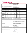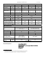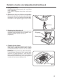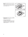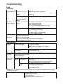
1
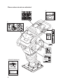
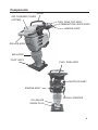
TAMPING RAMMER
MTX SERIES
INSTRUCTION MANUAL
302-02804
1) DECLARATION OF CONFORMITY
2) Manufacturer’s name and address.
Mikasa Sangyo Co., Ltd.
1-4-3 Sarugaku-cho, Chiyoda-ku, Tokyo, Japan
3) Name and address of the person who keeps the
technical documentation.
Takao Itoh, engineer
R. & D. Division, Mikasa Sangyo Co., Ltd.
Shiraoka-machi, Saitama, Japan
4) Type: Vibratory Rammers
MTX-60
MTX-70
MTX-80
MTX-90
51087 51089
51228 51229
51233
51265 51267
51275 51277
5) model
6) Equipment
item number
7) power sorce
Honda GX100U Honda GX100U Robin EH12-2D Robin EH12-2D
1.7kW
1.7kW
2.1kW
2.1kW
8) Measured
sound power
level(dB)
9) Guaranteed
sound power
level(dB)
10) Max. Sound
pressure
level(dB)
103
104
105
105
107
107
107
107
92
94
95
97
11) Conformity assessment according to Annex:
VIII (Full Quality Assurance procedure)
12) Name and address of the Notified Body
Société Nationale de Certification et d’Homologation (SNCH)
11, route de Luxembourg
L-5230 Sandweiler䇭LUXEMBOURG
13) Related Directive
Directive 2000/14/EC relating to the noise emission in the
environment by equipment for use outdoors.
14) Declaration
The equipment refer in this document, fulfills with all the
requirements of the Directive 2000/14/EC
15) Other related Community Directives
98/37/EC, 89/336/EEC, 2002/88/EC
EN500-1, EN500-4
16) EC Conformity Certificate No:
e13*2000/14*2000/14*0472*00
Tokyo, Japan
December, 2007
Signed by:
Mikasa Sangyo Co., Ltd.
17) Place and date of the declaration
Keiichi YOSHIDA
Director, General Manager R&D Division
㪇㪎㩾㪄㪈㪉㪄㪉㪌
㪪㫇㪼㪺㫀㪽㫀㪺㪸㫋㫀㫆㫅㩷㪽㫆㫉㩷㪤㪫㪯㪄㫊㪼㫉㫀㪼㫊
Rammer Specifications
Model
MTX-60
MTX-70
MTX-80
MTX-90
Overall height
mm
985
1,000
1,000
1,000
Overall width
mm
350
350
365
365
Overall length
mm
713
788
788
788
Shoe Size W x L
mm
265 x 340
10.7 䌾 㪈㪈㪅㪍
10.7 䌾 㪈㪈㪅㪍
10.7 䌾 㪈㪈㪅㪊
11.0 䌾 㪈㪈㪅㪍
(min )
mm
(644 䌾 695)
(644 䌾 695)
(642 䌾 679)
(660 䌾 698)
kN (kgf)
13.6 (1,390)
Hz
Number of Blow
-1
Jumping stroke
Impact Force
285 x 340
50 䌾 80
14.9 (1,520)
15.6 (1,590)
16.5 (1,680)
㪘㫌㫋㫆㫄㪸㫋㫀㪺㩷㪚㪼㫅㫋㫉㫀㪽㫌㪾㪸㫃
Clutch
Fuel Tank Capacity
liters
㪊㩷㫃㫀㫋㪼㫉㫊
2 liters
㪘㫌㫋㫆㫄㫆㪹㫀㫃㪼㩷㪦㫀㫃㩷㪪㪘㪜㩷㪈㪇㪮㪄㪊㪇㪒㩷㪚㫃㪸㫊㫊㩷㪪㪜㩷㫆㫉㩷㪿㫀㪾㪿㪼㫉
Lubricant for Body
Capacity of Lubricant
for Body
Operating weight
0.82
liters
0.65
kg
64 kg
75 kg
83 kg
89 kg
Guaranteed Sound Power Level
(in comply with 2000/14/EC)
107 dB
107 dB
107 dB
107 dB
Hand Arm Vibration (m/sec2) (in
comply with 2002/44/EC) 䌁䌨䌶
5.2
5.6
5.6
5.5
Engine Specifications
Model
Honda GX100U-KRBF
Robin EH12-2D46530
Type
㪘㫀㫉㪄㪚㫆㫆㫃㪼㪻㩷㪋㩷㪪㫋㫉㫆㫂㪼㪃㩷㪦㪟㪚㪃㩷㫊㫀㫅㪾㫃㪼㩷㪺㫐㫃㫀㫅㪻㪼㫉
㪾㪸㫊㫆㫃㫀㫅㪼㩷㪼㫅㪾㫀㫅㪼㪅
㪘㫀㫉㪄㪚㫆㫆㫃㪼㪻㩷㪋㩷㪪㫋㫉㫆㫂㪼㪃㩷㪦㪟㪭㪃
㫊㫀㫅㪾㫃㪼㩷㪺㫐㫃㫀㫅㪻㪼㫉㩷㪾㪸㫊㫆㫃㫀㫅㪼㩷㪼㫅㪾㫀㫅㪼㪅
㪛㫀㪸㫇㪿㫉㪸㪾㫄㩷㪫㫐㫇㪼
Caburetor System
cc
98
121
kw / rpm
2.1 / 3,600
2.6 / 3,600
rpm
㪊㪃㪏㪇㪇㩷㪄㩷㪋㪃㪈㪇㪇
Piston Displacement
Max. Output
Setting speed
Starting System
Spark plug
Only use the anti-EMI
(electromagnetic interference) type
Lubricant for Engine
Capacity of Lubricant
for Engine
Fuel
Standard Equipment:
㪊㪃㪋㪇㪇㩷㪄㩷㪊㪃㪍㪇㪇
㪊㪃㪌㪇㪇㩷㪄㩷㪊㪃㪎㪇㪇
㪩㪼㪺㫆㫀㫃㩷㪪㫋㪼㫉㫋㪼㫉
㪥㪞㪢㩷㪑㩷㪚㪩㪌㪟㪪㪙
㪛㪜㪥㪪㪦㩷㪑㩷㪬㪈㪍㪝㪪㪩㪄㪬㪙
㪥㪞㪢㩷㪑㩷㪙㪩㪍㪜㪪
㪘㫌㫋㫆㫄㫆㪹㫀㫃㪼㩷㪦㫀㫃㩷㪒㩷㪚㫃㪸㫊㫊㩷㪪㪜㩷㫆㫉㩷㪿㫀㪾㪿㪼㫉
liters
㪇㪅㪋
0.28
Unleaded Gasoline
㪫㫉㫀㫇㫃㪼㩷㪘㫀㫉㩷㪚㫃㪼㪸㫅㪼㫉㩷㪪㫐㫊㫋㪼㫄
㪟㫆㫌㫉㩷㩽㩷㪫㪸㪺㪿㫆㪄㫄㪼㫋㪼㫉
㪫㪿㫉㫆㫋㫋㫃㪼㩷㫃㪼㫍㪼㫉㩷㫎㪿㫀㪺㪿㩷㫌㫅㫀㫋㪼㪻㩷㫋㪿㪼㩷㪼㫅㪾㫀㫅㪼㩷㫊㫎㫀㫋㪺㪿㩷㪸㫅㪻㩷㫋㪿㪼㩷㪽㫌㪼㫃㩷㪺㫆㪺㫂
㪜㫅㪾㫀㫅㪼㩷㪧㫉㫆㫋㪼㪺㫋㫆㫉
㪩㫆㫃㫃㪼㫉㩷㫆㫅㩷㪟㪸㫅㪻㫃㪼
㪣㫀㪽㫋㫀㫅㪾㩷㪟㪸㫅㪻㫃㪼
䋪㪘㪹㫆㫌㫋㩷㪦㫇㪼㫉㪼㫋㫀㫆㫅㩷㫎㪼㫀㪾㪿㫋
䇭䇭㩷㪈㪀㩷㪝㫌㪼㫃㩷㫋㪸㫅㫂㩷㫀㫊㩷㪽㫀㫃㫃㪼㪻㩷㫌㫇㩷㫎㫀㫋㪿㩷㫆㫅㪼㩷㪿㪸㫃㪽㩷㫆㪽㩷㫋㪿㪼㩷㪽㫌㪼㫃㩷㫆㪽㩷㫉㪼㪾㫌㫃㪸㫋㫀㫆㫅㩷㫋㪸㫅㫂㩷㪺㪸㫇㪸㪺㫀㫋㫐㪅
䇭䇭㩷㪉㪀㩷㪦㫀㫃㩷㫄㪼㪸㫊㫌㫉㪼㩷㫆㪽㩷㫋㪿㪼㩷㪹㫆㪻㫐㩷㪸㫅㪻㩷㪼㫅㪾㫀㫅㪼㩷㫀㫊㩷㫀㫅㪺㫃㫌㪻㪼㪻㩷㫋㪿㪼㩷㫊㫋㪸㫋㪼㪻㩷㪺㪸㫇㪸㪺㫀㫋㫐
MTX TAMPING RAMMER INSTRUCTION MANUAL
Table of contents
Preface ............................................................................ 1
Application ........................................................................ 1
Warning about incorrect applications and techniques ..... 1
Structure ........................................................................... 1
Power transmission .......................................................... 1
Warning labels .................................................................. 2
Precautions for safety ....................................................... 2
General precautions .................................................... 2
Precautions when adding fuel ..................................... 3
Precautions about where to use the machine ............. 3
Precautions before starting work .............................. 3-4
Precautions while lifting ............................................... 4
Transportation and storage precautions ...................... 5
Maintenance precautions ............................................ 5
Places where decals are attached ................................... 6
Dimentions ....................................................................... 8
Components ................................................................... 9
Inspection before operation ........................................... 10
Operation ........................................................................ 11
Starting ...................................................................... 11
Operation .................................................................. 12
Stopping the machine .................................................... 13
Maintenance and storage ............................................... 14
Periodic checks and adjustments ................................... 14
Troubleshooting .............................................................. 17
Preface
This instruction manual describes the proper methods for using the tamping rammer, as well as
simple checks and maintenance. Be sure to read this instruction manual before using the
rammer, in order to get full use of the excellent performance of this machine, to improve your
operation and to perform engineering work effectively.
After reading this manual, store it in a handy location for easy reference.
For details about the engine in this machine, see the separate instruction manual for the
engine.
For inquiries about repair parts, parts lists, service manuals, and repair of the machine, please
contact the shop where you purchased it, our sales office, or the Mikasa Parts Service Center.
In addition, parts lists are available on the MIKASA website at:
http://www.mikasas.com/english/
The illustrations and Figures in this manual may be different from the machine you
actually purchased due to design changes and other reasons for improvement.
Application
Though compact and lightweight, this rammer creates a strong impact and you may expect a
large tamping effect on the ground.
It will compact nearly all types of soil, except soft soil that contains too much moisture.
Use this rammer to tamp the ground for creating roads, embankments, and to prepare the
surface to support buildings. It can also be used when burying gas or water lines, and electric
cables.
Warning about incorrect applications and techniques
Do not use this machine on ground that is harder than the machine can handle, or for driving
pilings or tamping rock beds. Furthermore, use of the machine on sloping ground such as the
side of an embankment, may be make the machine unstable and can cause an accident. It can
also result in premature machine wear due to uneven loads on the machine.
Use the machine with confidence for tamping earth and sand, soil, sand, gravel, and asphalt.
Do not use the machine for other type of jobs.
Structure
The upper section of the machine functions as a weight and consists of an engine section
guide, a gear reducer section, and reciprocating section. It also accommodates the handle and
the fuel tank sections, which are connected by rubber dampers.
The lower section of the machine which hits the ground, consists of a spring case to engage
sliding motion, a sloping section to allow the machine to tilt toward the front, bellows to cover
the foot, a sliding section, and a protective sleeve.
Power transmission
Power is provided by an air-cooled, 4-cycle, single-cylinder gasoline engine. The output end of
the engine crankshaft is equipped with a centrifugal clutch.
As the engine speed increases, the centrifugal clutch expands and a pinion gear that is a part
of the clutch drum engages a gear in the crank shaft on the main frame. The engine speed is
decreased in order to produce the required force for tamping.
The rotating motion of the main frame crankshaft is converted to a reciprocating motion through
a connecting rod. This reciprocating motion causes the foot to go up and down through a strong
coil spring. The weight of the main body and the strong force from the engine compress the
spring and the foot moves up and down, striking the ground forcefully.
1
Warning labels
The triangle shaped marks used in this manual and on the decals stuck on the
main body indicate common hazards. Be sure to read and observe the cautions
described.
䋣 Warning labels indicating hazards to humans and to equipment.
䋣 DANGER: Denotes an extreme hazard. It calls attention to a procedure,
practice, condition or the like, which, if not correctly performed
or adhered to, is likely to result in serious injury or death.
䋣 WARNING: Denotes a hazard. It calls attention to a procedure, practice,
condition or the like, which, if not correctly performed or
adhered to, could result in serious injury or death.
䋣 CAUTION: Denotes a hazard. It calls attention to a procedure, practice,
condition or the like, which, if not correctly performed or
adhered to, could result in injury to people and may damage or
destroy the product.
Precautions (without a triangular mark): Failure to follow the instructions may
result in damage to property.
Precautions for safety
General precautions
䋣 WARNING
■ DO NOT work in the following conditions.
- If you do not feel well due to overwork or illness.
- If you are taking any medicine.
- If you are under the influence of alcohol.
䋣 CAUTION
■ Read this instruction manual carefully
and handle the machine as described
so that you can work safely.
■ For details about the engine, refer the separate instruction manual for the engine.
Make sure you thoroughly understand the construction and operation of the machine.
■ To work safely, always wear
protective clothing (helmet, safety
glasses, safety shoes, ear plugs etc.)
and appropriate work clothes.
Always check the machine to make
sure that it is normal before starting
operation.
■ The decals on the machine body (operating methods, warning decals, etc.) are very
important to ensure safety. Keep the machine body clean so that they can be read at all
times. If any decal cannot be read, replace it with a new one.
■ It is very dangerous if children come into contact with the machine. Take the utmost care
about how and where the machine is stored.
■ Before performing any maintenance, be sure to turn the engine off.
■ Mikasa does not accept any liability for accidents or problems caused as a result of not
using genuine Mikasa parts (foot assembly, etc.), or if the machine has been modified.
2
Precautions when adding fuel
䋣 DANGER
■ When adding fuel.
- Be sure to work in a well ventilated location.
- Be sure to turn the engine off and wait until it has cooled down.
- Take the machine to a clear flat location without any combustibles nearby. Be careful not
any fuel. If you do spill some gasoline, wipe it all up.
- Do not allow any open flames nearby
while adding fuel. (In particular,
smoking while adding fuel is strictly
prohibited.)
■ Adding fuel until it comes too close to the top of the inlet may cause the fuel to overflow.
That is dangerous. Follow the instructions in the engine manual about the specified fuel
level.
■ When through adding fuel, tighten the tank cap securely.
Precautions about where to use the machine
䋣 DANGER
■ DO NOT run the engine in an
unventilated location, such as indoors
or in a tunnel. The exhaust gas from
the engine is carbon monoxide and is
deadly.
■ DO NOT operate the machine near
open fires.
Precautions before starting work
䋣 CAUTION
■ If you use the machine for a long time, be careful to watch for signs of vibration syndrome.
Since this machine vibrates, operation for a long time may have a negative effect on your
body. Take sufficient breaks while working.
■ Before starting to operate the machine, check for other people or obstacles that are too
close for safe operation.
■ When starting the engine, the rammer may jump suddenly. Hold the handle firmly with one
hand and pull the recoil starter with the other hand.
■ Always be careful around scaffolding. Operate the rammer in a stable manner so that it will
not become unbalanced.
■ During operation, don't let the foot of the machine come too close to your foot. The plate
may smash your foot.
■ The main parts of the engine, the
muffler, and muffler cover will be very
hot during operation. Be careful not to
touch them during operation or soon
after operation.
■ If you encounter any problems or abnormality with the machine during operation, while
moving it, or stopping operation, stop work immediately.
■ Before leaving the machine, be sure to turn the engine off. Also, make sure to turn the
engine off if you want to move the machine. When the throttle lever is in the stop position,
the fuel cock is closed. Do not move the lever away from the stop position.
■ When lifting the machine by the handle, be careful not to pinch your fingers between the
handle and main body.
3
Precautions before starting work(Continued)
䋣 DANGER
■ Take the utmost care not to allow the
machine to fall during work, or when
stopped or stored. Secure the
machine with a rope or similar tie
when stored or left idle so that it
cannot fall. If the rammer falls over
when children are around, a serious
accident may occur. If the machine
foot is worn, the machine will be
especially unstable. If the machine
foot is worn badly, replace it with a
new one.
■ If the machine falls over while working, the machine will move forward due to the kicking
motion of the foot while it is lying on its side. If the ground is solid, it will move quickly and is
very dangerous. To ensure that the operator and anyone nearby are safe, turn the throttle
lever to the engine stop position and make sure the machine stops. You must be extremely
careful when working on a road because a serious accident can easily occur.
Precautions while lifting
䋣 DANGER
■ Before lifting the machine, make sure that there is no damage to any of the components on
the machine (look especially for damage to the rubber dampers and the hook). There must
not be any loose or missing screws and the machine must generally be in a safe condition.
■ Turn the engine off before lifting the machine.
■ Use wire cables with enough strength to support the machine.
■ DO NOT lift it higher than necessary, for safety.
■ DO NOTuse a damaged wire cable.
■ Only use the single hook to lift the
machine. DO NOT support it from any
other points (such as the handle).
■ Never lift or lower the machine rapidly when using a hydraulic shovel or a crane.
■ When lifting the machine, do not allow any people or animals to pass under or near the
machine.
■ When using any type of equipment to lift the machine, be careful that the lifting equipment
does not cause an accident. Make sure you check the lifting equipment carefully, to ensure
that there are no problems or damage.
4
Transportation and storage precautions
䋣 DANGER
When transporting
■ Before transporting the machine, stop the engine.
■ DO NOT try to move it before the engine and machine body have cooled down enough.
■ Drain any fuel before transporting the machine.
■ Transport the rammer in a manner that keeps it level. If you must lay the machine down to
transport it, drain any fuel from the fuel tank and carburetor. Then close the fuel tank cap
and oil fill plug securely. Next, position the machine so that the carburetor will be facing up.
■ Secure the machine body so that the machine cannot move or fall during transportation.
■ When you want to lift the machine by gripping the handle, be careful not to pinch your
fingers or hands between the handle and the main body.
■ Since this machine is quite heavy, use a truck specifically designed to transport heavy
objects.
When storing the machine
■ After the engine and machine body have cooled down enough, store the rammer so that it is
level. Fasten the machine as needed so that the machine cannot fall down. If it you must lay
the machine down, close the fuel tank cap and oil fill plug securely. Arrange the machine
position so that the carburetor will be facing up. After it is lying down, make sure there are
no oil or fuel leaks. (If fuel is leaking, drain it all from the fuel tank.)
Maintenance precautions
䋣 WARNING
■ Appropriate maintenance of the machine is required to ensure safety and keep the machine
performing well. Always be aware of the machine's condition and keep it in good condition.
䋣 CAUTION
■ Be sure to turn the engine off before
checking or adjusting the machine.
■ The muffler and muffler guard
become very hot. Do not touch them
until they will have cooled down.
■ The lubrication oil and engine oil are
very hot and can burn you. Do not
start any maintenance on the
machine while the oil remains hot.
■ After performing any maintenance, check the condition of the safety components and the
general safety of the machine. In particular, check the nuts and bolts thoroughly.
■ If you have to disassemble any components on the machine, be sure to refer the
maintenance standard sheets and always work safely.
5
Places where decals are attached
1
4
02#
2
3
5
STOP
02#
02#
7
02# 6
11
/1&'./#%*+0'6;2'
/1&'../1&'..1/1&'.1
5'4+#.010&'5'4+'
(#$4+040/#64+%1.#
0/#64+%7.#
8(QUICK MANUAL)
9'+)*621+&5616#.
$'64'+$5)'9+%*6
2'51/#:2'5112'4#6+41
MI
17627627+55/#:+
.'+560)216'0<#/#55+/#
216'0%+#/#:
MY
Made in Japan
ᵫᵧᵩᵟᵱᵟᴾᵱᵟᵬᵥᵷᵭᴾᵡᵭᵌᵊᵪᵲᵢ
ᵏᵋᵒᵋᵑᵊᵱᵿᶐᶓᶅᵿᶉᶓᵋᶁᶆᶍᵊᵡᶆᶇᶗᶍᶂᵿᵋᶉᶓᵊᵲᶍᶉᶗᶍᵊᵨᵿᶎᵿᶌ
series
quick manual
Engine Oil
Use SAE 10W/30,SE or higher grade motor oil
RAMMING CYLINDER OIL
Use SAE 10W/30,SF or higher grade moter oil
Fuel
Use normal quality gasoline
6
,
No.
1
2
3
4
4
4
5
6
7
8
11
11
11
11
Part Name
DECAL,OPERATION
DECAL,AIR CLERNER
DECAL,LEVER OPERATION
DECAL,MAX SPEED 4100
DECAL,MAX SPEED 3600
DECAL,MAX SPEED 3700
DECAL,MACHINE STOP
DECAL,EC NOISE REQ.LWA107
DECAL,CHOKE OPERATION
QUICK MANUAL
PLATE,SERIAL NO./MTX-60
PLATE,SERIAL NO./MTX-70
PLATE,SERIAL NO./MTX-80
PLATE,SERIAL NO./MTX-90
Part No.
9202-12910
9202-12460
9202-12470
9202-12490
9202-12500
9202-12510
9202-12480
9202-10310
9202-12840
9202-12540
9202-13040
9202-12370
9202-12390
9202-12410
Remarks
MTX-60,70
MTX-80
MTX-90
MTX-60
MTX-70
MTX-80
MTX-90
Descriptions of the symbols on the warning decals
㪘
㪙
㪜
㪝
㪞
㪟
㪚
㪛
㪠
㪡
㪢
㪣
A. Read the instruction manual carefully
B. Wear protective clothing, such as safety glasses.
C. Wear protective clothing, such as ear protectors.
D. Fire hazard
E. Be careful not to get burned
F. Danger: poisonous exhaust gas
G. Lay the machine down carefully
H. Don't let your foot slip under the machine foot.
I. Lift point.
J. Lifting with a forklift is prohibited
K. Lifting the machine by the engine guard is prohibited
L. Fuel specification (gasoline)
Starting, running and stopping
1) Slide the throttle lever to the idle position.
2) Turn the choke lever to the "Closed" position.
3) Pull the recoil starter handle.
4) Turn the choke lever to the "Open" position.
5) Slide the throttle lever to the operating position.
6) After work, slide the throttle lever to the idle position.
7) After the machine has cooled down a little, slide the
throttle lever to the stop position.
Product number name plate
Product name, machine serial number, weight,
engine output, and CE mark
/1&'./#%*+0'6;2'
/1&'../1&'..1/1&'.1
5'4+#.010&'5'4+'
(#$4+040/#64+%1.#
0/#64+%7.#
9'+)*621+&5616#.
$'64'+$5)'9+%*6
2'51/#:2'5112'4#6+41
MI
17627627+55/#:+
.'+560)216'0<#/#55+/#
216'0%+#/#:
MY
Made in Japan
ᵫᵧᵩᵟᵱᵟᴾᵱᵟᵬᵥᵷᵭᴾᵡᵭᵌᵊᵪᵲᵢ
ᵏᵋᵒᵋᵑᵊᵱᵿᶐᶓᶅᵿᶉᶓᵋᶁᶆᶍᵊᵡᶆᶇᶗᶍᶂᵿᵋᶉᶓᵊᵲᶍᶉᶗᶍᵊᵨᵿᶎᵿᶌ
7
Dimentions
713/MTX-60
788/MTX-70,80,90
985/MTX-60
1000/MTX-70,80,90
350/MTX-60,70
365/MTX-80,90
265/MTX-60
285/MTX-70,80,90
8
340
Components
HOOK
AIR CLERNER COVER
(UPPER)
FUEL TANK CAP ASSY
COMBINATION LEVER ASSY
HANDLE ASSY
ROLLER ASSY
BELLOWS
FOOT ASSY
FUEL TANK ASSY
MUFFLER ASSY
ENGINE ASSY
OIL GAUGE
RECOIL STARTER
DRAIN PLUG
9
Inspection before operation
䋣 WARNING
■ Only check the machine while the engine is stopped. Otherwise, you may be caught by the
rotating components and be seriously injured.
■ Check the machine body only after it
has cooled down. The muffler is very
hot and you may be badly burned.
Inspection points
Appearance
Air cleaner
Bolts, nuts
Handle
Rubber damper
Engine oil
Main body lubrication oil
Fuel tank
Fuel system
Inspection items
Flaws, deformity, stains
Stains, flaws, deformation
Loose or missing parts
Flaws, deformity, cracks, breaks
Flaws, deformity, cracks, breaks
Color, oil level
Color, oil level
Leaks, fuel level, presence of dirt
Leaks, wear, loose parts
1 Clean each component thoroughly so that
there is no mud or dirt on it.
In particular, remove any mud on the machine
foot, and clean the area around the recoil
starter and carburetor.
2 Make sure that all of the screws are tight.
Loose screws may cause an accident due to
the vibration.
3 To check the engine oil, place the machine
body on a level surface and then tilt it forward.
(Figure 1)
For details about the engine, see the separate
instruction manual for the engine.
Oil level gauge
Fig.1
4 Place the machine body on a level surface and
look at the oil gauge on the protective sleeve,
from the right side. See if the oil is at the
specified level. (Figure 2)
Use 10W-30 engine oil rated SE or SF or
better for the engine.
䇭
Oil gauge assy
Drain plug
Fig.2
10
㪌 Add regular gasoline (Unleaded) to the fuel
tank and check the engine oil. Add oil before it
gets too low. Too little engine oil may cause
the engine to wear prematurely. (Figure 3)
Use 10W-30 engine oil rated SE or SF or
better for the engine.
䋣 DANGER: Fire hazard while refueling.
䋣 CAUTION: If any fuel spills, wipe it all up.
Fig.3
Operation
Starting
㪈 Slide the throttle lever from the stop to the idle
position( ). That opens the fuel cock and the
engine electrical circuit is turned on
automatically. (Figure 4)
Fig.4
㪉 Push the choke lever on the carburetor to the
closed position. When it is cold, close the
choke all the way. When it is hot, such as in
the summer, or when the engine is already hot,
open the choke a little or leave it fully open.
If the engine cannot be started, open the
choke a little so as not to flood the carburetor.
(Figure 5)
Fig.5
㪊 Hold the recoil starter handle and pull it a little.
You will feel resistance. Then, pull it hard to
turn the engine. Allow the starter cord to return
slowly into the case before letting go of the
handle. (Figure 6)
Fig.6
11
4 After the engine has started, open the choke
lever gradually until it is wide open. Pay
attention to the sound of the engine to guide
you in the amount to open the choke. After the
engine has started, be sure to warm up the
engine at low speed for 3 to 5 minutes. During
this time, check the machine for leaking fuel,
abnormal sounds, or abnormal exhaust color
or odor.
CAUTION: When warming up, if in the semiclutch in order not to be,pay
attention to engine speed.
5 If the engine cannot be started after pulling the
starter handle several times, remove the spark
plug and see if it has a spark. If the plug is wet
from fuel (due to flooding from the carburetor),
or if it is stained, replace the plug or clean it
thoroughly. While the plug is removed, pull the
starter handle 2 to 3 times to discharge any
fuel from the cylinder.
Operation
1 Shift the throttle lever from idle( ) to the
operating position( ) (Figure 7) and the
tamping rammer will start vibrating. Shifting the
lever slowly will cause irregular operation and
damage the clutch, springs, and foot.
CAUTION: If you start it operating too quickly
the engine may stop due to the
operation of the carburetor.
Fig.7
2 After operation is started, adjust the throttle
lever a little until the rammer tamps the soil
correctly. When the engine is running within
the specified rpm range, the rammer will be the
most effective. If the engine runs too fast, the
tamping force will not be increased. Instead,
t h e sp r ing r es onanc e w i l l dec r e a se t h e
tamping force and damage the machine.
䋣
If you start it operating too quickly
the engine may stop due to the
operation of the carburetor.
WARNING: If the rammer is used on sloping
ground, check the safety of the
surroundings and be careful not to
allow the machine to fall over.
12
3 In the cold season, the oil in the machine will be
thicker, and the resistance of the components
will be much larger, which may cause irregular
motion. Shift the throttle lever from the
operation to the idle position several times and
allow it to warm up sufficiently before starting
actual work.
4 The surface of the foot in contact with the
ground is a metal sheet that has excellent wear
resistance. However if you need to tamp ground
that contains large stones (about the size of a
fist), first put some fill soil over them so that the
foot will tamp the ground evenly.
5 The machine body will advance as it jumps. If
you want to move forward faster, push the
handle a little forward to make the machine
body lean a little forward.
6 To halt work, quickly slide the throttle lever from
the operation position( ) to the idle position
( ). Do not slide the throttle lever slowly
(Figure 8).
Fig.8
Stopping the machine
1 Slide the throttle lever from the operation
position( ) to the idle position( ). Run the
engine at low speed for 3 to 5 minutes to cool it
down. Then slide the throttle lever from the idle
position to the stop position. The engine will
stop and the fuel cock is closed automatically.
(Figure 9)
fig.9
2 If the engine does not stop due to a problem
with the switch or something similar, take the
machine to a safe location and hold the throttle
lever in the stop position. Let the machine run in
idle and the engine will stop after a few
minutes.
13
Maintenance and storage
1 Wash off any dirt or mud on each part of the
machine using fresh water.
2 After the engine and main body have cooled
down, store the rammer on a level location.
Secure the machine body so that it can not fall
down. If you have to lay the machine down,
close the fuel tank cap securely and tighten
engine oil drain plug. After the engine and
machine body have cooled down, lay the
machine so that the carburetor is facing up.
Once the machine has been laid down, make
sure that there are no fuel lubrication oil leaks.
(If the fuel leaks, drain the fuel from the fuel
tank.)
3 Put a cover on the machine body to prevent
dirt landing on it. Store the machine in a
location that is not exposed to direct sunlight
and which has low humidity.
4 For prolonged storage
- Slide the throttle lever to the stop position.
- Drain any fuel and replace the lubrication oil.
Apply grease to the lubrication points.
Be sure to remove any fuel in the fuel hose,
too.
- Cover the air intake on the air cleaner and
the exhaust outlet on the muffler.
- Store the machine indoors. Do not leave it
outside.
Periodic checks and adjustments
Table of scheduled checks
How often?
Daily
(before starting operation)
After first 20 hours
Every 50 hours
Every 200 hours
Every 200 to 300 hours
Every 2 years
14
Place to check
Appearance
Air cleaner
Bolts, nuts
Handle
Rubber damper
Engine oil
Lubrication oil in
the main body
Fuel tank
Fuel system
Engine oil
Spark plug
Engine oil
Lubrication oil in
the main body
Pre-air cleaner
(primary element)
Fuel hose
Item to check
Flaws, deformity, dirt
Dirt, flaws, deformation
Loose or missing parts
Flaws, deformity, cracks, damage
Wear, deformity, cracks, damage
Dirt, oil level
Dirt, oil level
Leaks, fuel level, dirt
Leaks, wear, looseness
Replace once, after the first 20 hours
Clean, adjust gap
Replace
Replace
Cleaning
Replace
Oil etc.
Engine oil
Engine oil
Gasoline
Engine oil
Engine oil
Engine oil
Lamp kerosene
Periodic checks and adjustments(Continued)
1 Daily maintenance
Carefully wipe off any mud, dirt or oil from
each component.
If oil leaks, retighten the joints and check
again.
2 Maintenance after every 50 hours of operation
Remove the fuel filter cup and clean the inside
thoroughly. (Figure 10) Remove the spark plug
and clean it. Then adjust the gap to 0.6 to 0.7 mm.
Fuel filter
fig.10
3 Replacing the lubrication oil
Remove the drain plug on the lower part of the
machine body and drain the oil inside. Then
add the specified amount of new oil.
(Figure 11)
Oil gauge
Drain plug
fig.11
4 Cleaning the air cleaner
Remove the upper air cleaner cover on the
main body. Loosen and remove the 2 Phillips
screws that hold the cover on the air cleaner
assembly.
a. Primary element (clean every 80 to 100 hours)
If the primary element is dirty, wash it with
gasoline or lamp kerosene. Then, dip it in
engine oil SAE10W-30 and wring it out. (Wring
the element so that 25 to 30 cc of engine oil
remains in the element.) (Figure 12)
Primary element
fig.12
15
b. Secondary element (clean every 100 to 150
hours)
When the secondary element (under the
primary element) becomes dirty, wash it with
neutral detergent solution and dry it well. Then
reuse it. (Figures 13, 14)
Secondary element
fig.13
fig.14
5 Be sure to check the fuel line for damaged
or looseness.
Replace the fuel line every 2 years, even if it
does not show any abnormality.
6 Cleaning the machine body
If you want to clean the machine body using
high-pressure steam, do not spray water
directly into the air cleaner, carburetor, muffler,
or top of the fuel tank. Otherwise engine
problems may occur.
16
Troubleshooting
Engine
1.Won't start
Fuel is present
but the spark plug
is not sparking.
Fuel and spark
are both present.
Fuel is not being
supplied to the
carburetor.
Electricity is being
supplied to the
high voltage
cable.
Electricity is not
being supplied to
the high voltage
cable
Compression is
good
The gap in the spark plug tip is clogged.
Carbon is stuck on the spark plug
The spark plug has a short circuit due to faulty
insulation.
The gap in the spark plug is the wrong size.
The stop button switch has a short circuit.
The ignition coil is broken.
The muffler is clogged with carbon.
The wrong fuel was used.
The air cleaner is clogged.
The fuel is contaminated with water or dirt.
The cylinder head gasket is blown or the head is not
correctly tightened.
Compression is
The piston rings don't fit well.
low
The cylinder is worn.
The spark plug is not seated tightly.
The valve seat is damaged.
No fuel in the fuel tank.
Faulty fuel cock operation.
The fuel filter is clogged.
The air hole in the cap on the fuel tank is clogged.
Air is trapped in the fuel line.
2.Faulty operation
Too little
power
Engine
overheats
Smoke
comes from
the muffler
Dirt in the air cleaner.
Air trapped in the fuel line.
Carbon has accumulated in the cylinder.
Low compression (See ”Compression in low” above
Faulty ignition coil.
Good compression
Dirt on the spark plug.
but misfires
Ignition coil shorts sometimes.
Excessive accumulation of carbon in the combustion chamber.
Clog exhaust port or muffler.
Faulty spark plug.
Choke lever wasn't returned to the open position.
Black smoke
Good
Blended oil (for 2-cycle engines) was used.
Blue
Too much oil.
smoke compression
Engine oil leaked into the air cleaner when the
machine was laid down on the wrong side.
Compression
Worn piston rings.
is low
The piston rings don't fit well.
Moisture in the gasoline.
White smoke
The air cleaner is wet.
Good compression
and no misfiring
(In the winter, the machine may emit white smoke for a while when first started in the morning.
This is not abnormal.)
Engine speed fluctuates
Faulty governor adjustment.
Faulty governor spring.
Faulty fuel flow.
Air being sucked into the fuel line.
17
Note
- - - - - - - - - - - - - - - - - - - - - - - - - - - - - - - - - - - - - - - - - - - - - - - - - - - - - - - - - - - - - - - - - - - - - - - - - - - - - - - - - - - - - - - - - - - - - - - - - - - - - - - - - - - - - - - - - - - - - - - - - - - - - - - - - - - - - - - - - - - - - - - - - - - - - - - - - - - - - - - - - - - - - - - - - - - - - - - - - - - - - - - - - - - - - - - - - - - - - - - - - - - - - - - - - - - - - - - - - - - - - - - - - - - - - - - - - - - - - - - - - - - - - - - - - - - - - - - - - - - - - - - - - - - - - - - - - - - - - - - - - - - - - - - - - - - - - - - - - - - - - - - - - - - - - - - - - - - - - - - - - - - - - - - - - - - - - - - - - - - - - - - - - - - - - - - - - - - - - - - - - - - - - - - - - - - - - - - - - - - - - - - - - - - - - - - - - - - - - - - - - - - - - - - - - - - - - - - - - - - - - - - - - - - - - - - - - - - - - - - - - - - - - - - - - - - - - - - - - - - - - - - - - - - - - - - - - - - - - - - - - - - - - - - - - - - - - - - - - - - - - - - - - - - - - - - - - - - - - - - - - - - - - - - - - - - - - - - - - - - - - - - - - - - - - - - - - - - - - - - - - - - - - - - - - - - - - - - - - - - - - - - - - - - - - - - - - - - - - - - - - - - - - - - - - - - - - - - - - - - - - - - - - - - - - - - - - - - - - - - - - - - - - - - - - - - - - - - - - - - - - - - - - - - - - - - - - - - - - - - - - - - - - - - - - - - - - - - - - - - - - - - - - - - - - - - - - - - - - - - - - - - - - - - - - - - - - - - - - - - - - - - - - - - - - - - - - - - - - - - - - - - - - - - - - - - - - - - - - - - - - - - - - - - - - - - - - - - - - - - - - - - - - - - - - - - - - - - - - - - - - - - - - - - - - - - - - - - - - - - - - - - - - - - - - - - - - - - - - - - - - - - - - - - - - - - - - - - - - - - - - - - - - - - - - - - - - - - - - - - - - - - - - - - - - - - - - - - - - - - - - - - - - - - - - - - - - - - - - - - - - - - - - - - - - - - - - - - - - - - - - - - - - - - - - - - - - - - - - - - - - - - - - - - - - - - - - - - - - - - - - - - - - - - - - - - - - - - - - - - - -