1
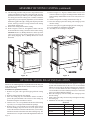
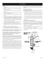
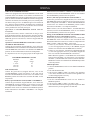
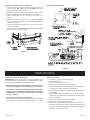
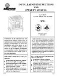
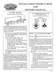
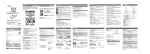
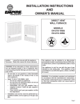
INSTALLATION INSTRUCTIONS
AND
OWNER'S MANUAL
The Classic Cast Iron Stoves
CAST IRON
VENTED FIREPLACE HEATER
MODEL
CIBV-30-20
Installer: Leave this manual with the appliance.
Consumer: Retain this manual for future reference.
WARNING: If the information in these instructions are not followed exactly, a fire or explosion may result causing property damage,
personal injury or loss of life.
— Do not store or use gasoline or other flammable vapors and liquids in the vicinity of this or
any other appliance.
— WHAT TO DO IF YOU SMELL GAS
• Do not try to light any appliance.
• Do not touch any electrical switch; do not
use any phone in your building.
• Immediately call your gas supplier from a
neighbor’s phone. Follow the gas supplier’s instructions.
• If you cannot reach your gas supplier, call
the fire department.
— Installation and service must be performed
by a qualified installer, service agency or the
gas supplier.
AVERTISSEMENT: Assurez vous de bien
suivre les instructions données dans cette notice
pour réduire au minimum le risque d’incendie
ou d’explosion ou pour éviter tout dommage
matériel, toute blessure ou la mort.
— Ne pas entreposer ni utiliser d’essence ni
d’autres vapeurs ou liquides inflammables
dans le voisnage de cet appareil ou de tout autre appareil.
— QUE FAIRE SI VOUS SENTEZ UNE ODEUR
DE GAZ:
• Ne pas tenter d’allumer d’appareil.
• Ne touchez a aucun interrupteur. Ne pas
vous servir des téléphones se trouvant
dans le bâtiment où vous vous trouvez.
• Appelez immédiatement votre fournisseur
de gaz depuis un voisin. Suivez les instructions du fournisseur.
• Si vous ne pouvez rejoindre le fournisseur
de gaz, appelez le service des incendies.
— L’installation et l’entretien doivent être assurés par un installateur ou un service
d’entretien qualifié ou par le fournisseur de
gaz.
Page 1
TABLE OF CONTENTS
SECTION
PAGE
Important Safety Information .................................................................................................3
Safety Information for Users of LP Gas .................................................................................4
Introduction ............................................................................................................................5
Specifications .........................................................................................................................6
Gas Supply .............................................................................................................................7
Clearances .............................................................................................................................8
Appliance Hardware Package ................................................................................................9
Assembly of Stove Casting .............................................................................................. 9-12
Optional Stone Inlay Installation..........................................................................................12
Wire Channel Installation .....................................................................................................13
Log Placement ......................................................................................................................13
Operating Guidelines............................................................................................................14
Vent Safety Shutoff System ..................................................................................................14
Venting .................................................................................................................................15
Lighting Instructions ...........................................................................................................16
Pilot Flame Characteristics...................................................................................................17
Main Burner Flame Characteristics......................................................................................17
Wiring ............................................................................................................................ 18-19
Maintenance ................................................................................................................... 19-20
Troubleshooting ................................................................................................................... 21
How To Order Repair Parts ..................................................................................................22
Parts List for CIBV-30-20 ...................................................................................................22
Parts View for CIBV-30-20 ................................................................................................23
Parts List for Stove Casting ..................................................................................................24
Parts View for Stove Casting................................................................................................25
Optional Blower Installation Instructions ..................................................................... 26-27
Page 2
15627-5-0807
IMPORTANT SAFETY INFORMATION
THIS IS A HEATING APPLIANCE
DO NOT OPERATE THIS APPLIANCE WITHOUT FRONT PANEL INSTALLED.
• Due to high temperatures, the fireplace heater should be
located out of traffic and away from furniture and draperies.
• Children and adults should be alerted to the hazards of
high surface temperature and should stay away to avoid
burns or clothing ignition.
• Young children should be carefully supervised when they
are in the same room as the fireplace heater.
• Clothing or other flammable material should not be placed
on or near the fireplace heater.
• Surveiller les enfants. Garder les vêtements, les meubles,
l'essence ou autres liquides à vapeur inflammables lin de
l'appareil.
• Due to high surface temperatures, keep children, clothing
and furniture away.
• The glass front or any part removed for servicing the
appliance must be replaced prior to operating the appliance.
Work should be done by a qualified service person.
• Keep burner and control compartment clean.
• Installation and repair should be done by a QUALIFIED
SERVICE PERSON. The fireplace heater should be
inspected before use and at least annually by a qualified
service person. More frequent cleaning may be required
due to excessive lint from carpeting, bedding material,
etc. It is imperative that control compartments, burners
and circulating air passageways of the fireplace heater be
kept clean.
• S'assurer que le brûleur et le compartiment des commandes sont propres. Voir les instructions d'installation et
d'utilisation qui accompagnent l'appareil.
• DO examine burners periodically. Clean and replace damaged parts.
• CAUTION: The glass used in your heater is a special
high temperature ceramic glass. If the glass is cracked
or damaged in any way, it should be replaced only with
a complete glass frame assembly from Empire. See parts
list on Page 22 for ordering.
• DO NOT use this heater if any part has been under water.
Immediately call a qualified service technician to inspect
the heater and to replace any part of the control system
and any gas control which has been under water.
• Ne pas se servir de cet appareil s'il a été plongé dans l'eau,
complètement ou en partie. Appeler un technicien qualifié
pour inspecter l'appareil et remplacer toute partie du
système de contrôle et toute commande qui ont été plongés
dans l'eau.
• Under no circumstances should any solid fuels (wood,
coal, paper or cardboard etc.) be used in this appliance.
• WARNING: Any change to this fireplace heater or its
controls can be dangerous. Any safety screen or guard
removed for servicing a fireplace heater must be replaced
prior to operating the fireplace heater
• WARNING: If not installed, operated and maintained
in accordance with the manufacturer's instructions, this
product could expose you to substances in fuel or from fuel
combustion which can cause death or serious illness.
• WARNING: Do not operate appliance with the glass
front removed, cracked or broken. Replacement of the
glass should be done by a licensed or qualified service
person.
• DO keep the appliance area clear and free from combustible material, gasoline and other flammable vapors and
liquids.
15627-5-0807
Page 3
SAFETY INFORMATION FOR USERS OF LP-GAS
Propane (LP-Gas) is a flammable gas which can cause fires
and explosions. In its natural state, propane is odorless and
colorless. You may not know all the following safety precautions
which can protect both you and your family from an accident.
Read them carefully now, then review them point by point
with the members of your household. Someday when there
may not be a minute to lose, everyone's safety will depend on
knowing exactly what to do. If, after reading the following
information, you feel you still need more information, please
contact your gas supplier.
LP-GAS WARNING ODOR
If a gas leak happens, you should be able to smell the gas because of the odorant put in the LP-Gas.
That's your signal to go into immediate action!
•
•
•
•
Do not operate electric switches, light matches, use your
phone. Do not do anything that could ignite the gas.
Get everyone out of the building, vehicle, trailer, or area.
Do that IMMEDIATELY.
Close all gas tank or cylinder supply valves.
LP-Gas is heavier than air and may settle in low areas such
as basements. When you have reason to suspect a gas leak,
keep out of basements and other low areas. Stay out until
firefighters declare them to be safe.
•
•
Use your neighbor's phone and call a trained LP-Gas service
person and the fire department. Even though you may not
continue to smell gas, do not turn on the gas again. Do not
re-enter the building, vehicle, trailer, or area.
Finally, let the service man and firefighters check for escaped
gas. Have them air out the area before you return. Properly
trained LP-Gas service people should repair the leak, then
check and relight the gas appliance for you.
NO ODOR DETECTED - ODOR FADE
Some people cannot smell well. Some people cannot smell the
odor of the chemical put into the gas. You must find out if you
can smell the odorant in propane. Smoking can decrease your
ability to smell. Being around an odor for a time can affect your
sensitivity or ability to detect that odor. Sometimes other odors
in the area mask the gas odor. People may not smell the gas odor
or their minds are on something else. Thinking about smelling a
gas odor can make it easier to smell.
The odorant in LP-gas is colorless, and it can fade under some
circumstances. For example, if there is an underground leak, the
movement of the gas through soil can filter the odorant. Odorants
in LP-Gas also are subject to oxidation. This fading can occur if
there is rust inside the storage tank or in iron gas pipes.
The odorant in escaped gas can adsorb or absorb onto or into walls,
masonry and other materials and fabrics in a room. That will take
some of the odorant out of the gas, reducing its odor intensity.
LP-Gas may stratify in a closed area, and the odor intensity could
vary at different levels. Since it is heavier than air, there may be
more odor at lower levels. Always be sensitive to the slightest gas
odor. If you detect any odor, treat it as a serious leak. Immediately
go into action as instructed earlier.
SOME POINTS TO REMEMBER
•
Learn to recognize the odor of LP-gas. Your local LP-Gas
Dealer can give you a "Scratch and Sniff" pamphlet. Use it
to find out what the propane odor smells like. If you suspect
that your LP-Gas has a weak or abnormal odor, call your
LP-Gas Dealer.
•
If you are not qualified, do not light pilot lights, perform
service, or make adjustments to appliances on the LP-Gas
system. If you are qualified, consciously think about the odor
of LP-Gas prior to and while lighting pilot lights or performing service or making adjustments.
•
Sometimes a basement or a closed-up house has a musty
smell that can cover up the LP-Gas odor. Do not try to light
pilot lights, perform service, or make adjustments in an area
where the conditions are such that you may not detect the
odor if there has been a leak of LP-Gas.
•
Odor fade, due to oxidation by rust or adsorption on walls
of new cylinders and tanks, is possible. Therefore, people
should be particularly alert and careful when new tanks or
cylinders are placed in service. Odor fade can occur in new
tanks, or reinstalled old tanks, if they are filled and allowed
to set too long before refilling. Cylinders and tanks which
Page 4
have been out of service for a time may develop internal rust
which will cause odor fade. If such conditions are suspected
to exist, a periodic sniff test of the gas is advisable. If you
have any question about the gas odor, call your LP-gas
dealer. A periodic sniff test of the LP-gas is a good safety
measure under any condition.
•
If, at any time, you do not smell the LP-Gas odorant and you
think you should, assume you have a leak. Then take the same
immediate action recommended above for the occasion when
you do detect the odorized LP-Gas.
•
If you experience a complete "gas out," (the container is under no vapor pressure), turn the tank valve off immediately.
If the container valve is left on, the container may draw in
some air through openings such as pilot light orifices. If this
occurs, some new internal rusting could occur. If the valve is
left open, then treat the container as a new tank. Always be
sure your container is under vapor pressure by turning it off
at the container before it goes completely empty or having
it refilled before it is completely empty.
15627-5-0807
INTRODUCTION
Introduction
Always consult your local Building Department regarding
regulations, codes or ordinances which apply to the installation
of a vented fireplace heater.
Instructions to Installer
1. Installer must leave instruction manual with owner after
installation.
2. Installer must have owner fill out and mail warranty card
supplied with heater.
3. Installer should show owner how to start and operate heater
and thermostat.
General Information
This appliance is design certified in accordance with American
National Standard /CSA Standard ANSI Z21.88 and CSA 2.33 by
the Canadian Standards Association, as a Vented Fireplace Heater
and must be installed according to these instructions.
Any alteration of the original design, installed other than
as shown in these instructions or use with a type of gas not
shown on the rating plate is the responsibility of the person
and company making the change.
Important
All correspondence should refer to complete Model Number,
Serial Number and type of gas.
Notice: During initial firing of this unit, its paint will bake out
and smoke will occur. To prevent triggering of smoke alarms,
ventilate the room in which the unit is installed.
Qualified Installing Agency
Installation and replacement of gas piping, gas utilization
equipment or accessories and repair and servicing of equipment
shall be performed only by a qualified agency. The term "qualified
agency" means any individual, firm, corporation or company
which either in person or through a representative is engaged in
and is responsible for (a) the installation or replacement of gas
piping or (b) the connection, installation, repair or servicing of
equipment, who is experienced in such work, familiar with all
precautions required and has complied with all the requirements
of the authority having jurisdiction.
State of Massachusetts: The installation must be made by
a licensed plumber or gas fitter in the Commonwealth of
Massachusetts.
The installation must conform with local codes or, in the absence
of local codes, with the National Fuel Gas Code, ANSI Z223.1/
NFPA 54.*
High Altitudes
When installing this unit at an elevation above 2000 feet (in the
United States) it may be necessary to decrease the input rating by
changing the existing burner orifice to a smaller size. Generally,
input should be reduced 4 percent for each 1000 feet above sea
level. However, if the heating value of the gas has been reduced,
this general rule may not apply. Check with local gas utility for
proper orifice size identification.
APPLIES TO CANADIAN MODELS ONLY FOR PROPANE
GAS.
Altitude: 0-4,500 feet (0-1370 m) without orifice change.
APPLIES TO CANADIAN MODELS ONLY FOR NATURAL
GAS.
Altitude 0-2,000 feet (0-610m) without orifice change.
Cet appareil est équipé pour des altitudes compris entre 0 et
2000 pieds (0-610m) seulement.
For installations from 610-1370 metres (2,000-4,500 ft.) the
orifice size (DMS) for natural gas is 39. See data plate for
additional information.
For high altitude installations consult the local gas distributor or
the authority having jurisdiction for proper rating methods. If the
installer must convert the unit to adjust for varying altitudes, the
information sticker (illustrated below) must be filled out by the
installer and adhered to the appliance at the time of conversion.
THE CONVERSION SHALL BE CARRIED OUT BY A MANUFACTURER'S AUTHORIZED REPRESENTATIVE IN ACCORDANCE WITH THE REQUIREMENTS OF THE MANUFACTURER, PROVINCIAL OR TERRITORIALAUTHORITIES
HAVING JURISDICTION AND IN ACCORDANCE WITH THE
REQUIREMENTS OF THE CAN/CGA-B141.1 OR CAN/CGAB141.2 INSTALLATION CODES.
LA CONVERSION DOIT ÊTRE EFFECTUÉE CONFORMÉMENT AUX RÉGLEMENTATION PROVINCIAUX EN
CAUSE ET AUX EXIGENCES DES CODES D'INSTALLATION
CAN/CGA-B149.
This appliance has been converted for use at an altitude of
Orifice size
Manifold Pressure
Input (Btu/h)
Fuel Type
Date of Conversion
Converted by
Cet appareil a été converti au
Injecteur
Pression à la tubulure d'alimentation
Déoit calorifique
*Available from the American National Standards Institute, Inc., 11 West 42nd
St., New York, N.Y. 10036.
15627-5-0807
Page 5
SPECIFICATIONS
Model
Input BTU/HR (KW/H) Maximum
BTU/HR (KW/H) Minimum
Height
Width
Depth including diverter
Gas Inlet
Size Draft Diverter Collar
Floor to top of collar on vertical position of Draft Diverter
Floor to center of collar on horizontal position of Draft
Diverter
Stove Casting (Must be ordered with Firebox)
CIFB-1
CIPB-1
CIPG-1
CIPS-1
CIPN-1
CIPR-1
Accessories
TMV
FRBC-1
FRBTC-1
FREC-1
FWS-1
CIB-2
Stone Inlay Replaces Standard Grill Top
CII-2
Stone Inlay
CII-3
Stone Inlay
CII-4
Stone Inlay
CII-5
Stone Inlay
CII-6
Stone Inlay
CII-7
Stone Inlay
Page 6
CIBV-30
30,000 (8.7)
21,000 (6.2)
27 3/4" (704mm)
25 `/1" (647mm)
21" (533mm)
1/2" (13mm)
4" (101mm)
27 3/8" (695mm)
23 1/2" (596mm)
Flat Black
Porcelain Black
Porcelain Green
Porcelain Sand
Porcelain Navy
Porcelain Red
Millivolt Wall Thermostat - Reed Switch
Battery Operated Remote Control
Battery Operated Remote Control w/Thermostat
Electric Remote Control
Wall Switch
Automatic Blower
Empress Green
Hunan Jade
Gray Botticino
Azul
Salome
Black Swan
15627-5-0807
GAS SUPPLY
Consult the current National Fuel Gas Code, ANSI Z223.1 CAN/
CGA-B149 (.1 or .2) installation code.
Recommended Gas Pipe Diameter
Pipe Length
Schedule 40 Pipe
Tubing, Type L
Inside Diameter
Outside Diameter
Nat.
L.P.
Nat.
L.P.
0-10 feet
1/2”
3/8”
1/2”
3/8”
0-3 meters
12.7mm 9.5mm 12.7mm 9.5mm
10-40 feet
1/2”
1/2”
5/8”
1/2”
4-12 meters 12.7mm 12.7mm 15.9mm 12.7mm
40-100 feet
1/2”
1/2”
3/4”
1/2”
13-30 meters 12.7mm 12.7mm
19mm 12.7mm
100-150 feet
3/4”
1/2”
7/8”
3/4”
31-46 meters 19mm 12.7mm 22.2mm 19mm
Note: Never use plastic pipe. Check to confirm whether your local
codes allow copper tubing or galvanized.
Note: Since some municipalities have additional local codes,
it is always best to consult your local authority and installation
code.
The use of the following gas connectors is recommended:
— ANS Z21.24 Appliance Connectors of Corrugated Metal
Tubing and Fittings
— ANS Z21.45 Assembled Flexible Appliance Connectors of
Other Than All-Metal Construction
The above connectors may be used if acceptable by the authority
having jurisdiction. The state of Massachusetts requires that a
flexible appliance connector cannot exceed three feet in length.
Installing a New Main Gas Cock
Each appliance should have its own manual gas cock.
A manual main gas cock should be located in the vicinity of
the unit. Where none exists, or where its size or location is not
adequate, contact your local authorized installer for installation
or relocation.
Compounds used on threaded joints of gas piping shall be resistant
to the action of liquefied petroleum gases. The gas lines must be
checked for leaks by the installer. This should be done with a soap
solution watching for bubbles on all exposed connections, and if
unexposed, a pressure test should be made.
Never use an exposed flame to check for leaks. Appliance must
be disconnected from piping at inlet of control valve and pipe
capped or plugged for pressure test. Never pressure test with
appliance connected; control valve will sustain damage!
NOTE: The gas control is equipped with a captured screw type
pressure test point, therefore it is not necessary to provide a 1/8"
test point up stream of the control.
A gas valve and ground joint union should be installed in the gas
line upstream of the gas control to aid in servicing. It is required
by the National Fuel Gas Code that a drip line be installed near
the gas inlet. This should consist of a vertical length of pipe tee
connected into the gas line that is capped on the bottom in which
condensation and foreign particles may collect.
When using copper or flex connector use only approved fittings.
Always provide a union so that gas line can be easily disconnected
for burner servicing.
The appliance and it's individual shut off valve must be disconnected
from supply piping system during any pressure testing of that
system at test pressures in excess of 1/2 psig (3.5kPa).
The appliance must be isolated from the gas supply piping system
by closing its individual manual shut off valve during any pressure
testing of the gas supply piping system at test pressures equal to
or less than 1/2 psig (3.5kPa).
Attention! If one of the procedures results in pressures in excess
of 1/2 psig (14" w.c.) (3.5 kPa) on the fireplace gas valve, it will
result in a hazardous condition.
Figure 1
15627-5-0807
Checking Manifold Pressure
Both Propane and Natural gas valves have a built-in pressure
regulator in the gas valve. Natural gas models will have a manifold
pressure of approximately 3.5" w.c. (.871kPa) for maximum input
or 1.7" w.c. (.423kPa) for minimum input at the valve outlet
with the inlet pressure to the valve from a minimum of 5.0" w.c.
(1.245kPa) for the purpose of input adjustment to a maximum of
10.5" (2.615kPa) w.c. Propane gas models will have a manifold
pressure approximately 10.0"w.c. (2.49kPa) for maximum input
or 5.9" w.c. (1.469kPa) for minimum input at the valve outlet
with the inlet pressure to the valve from a minimum of 11.0" w.c.
(2.739kPa) for the purpose of input adjustment to a maximum of
13.0" w.c. (3.237kPa).
A 1/8" (3mm) N.P.T. plugged tapping, accessible for test gauge
connection, is located on the outlet side of the gas control.
Page 7
CLEARANCES
Clearances: When facing the front of the fireplace heater the
minimum clearances to combustible construction (material) are
the following:
Open in front to provide service, access, and clearance to
construction.
Top of appliance (ceiling)
36 (inches)
Draft Diverter to Rear Wall
2 (inches)
Side Wall
6 (inches)
Heater Corners (45° angle) to Wall
4 (inches)
Floor
0 (inches)
Installation on Rugs and Tile
If this appliance is to be installed directly on carpeting, tile, or
other combustible material, other than wood flooring, the appliance shall be installed on a metal or wood panel extending the
full width and depth of the appliance.
The base referred to above does not mean the fire-proof base as
used on wood stoves. The protection is primarily for rugs that may
be extremely thick and light-color tile that can discolor.
(914mm) TO CEILING
OR HORIZONTAL
PROJECTION ABOVE
APPLIANCE
Figure 3
Figure 2
Figure 4
Page 8
15627-5-0807
APPLIANCE HARDWARE PACKAGE
Appliance Hardware Package Parts List
Part
Description
Part
Number
Quantity
Supplied
1/42-0 x 1" Phillips Head Bolt
R-3188
4
1/4-20 x 3/8" Phillips Head Bolt
R-3646
16
1/4-20 x 1/2" Leveling Bolt
R-3747
4
No. 10 x 1/2" Hex Washer Head Screw
R-2737
10
1/4-20 Washer Head Nut
R-3185
4
Leg Pad "A" (see Figure 6)
CI-008
2
Leg Pad "B" (see Figure 6)
CI-009
2
1-1/4" x 1/2" Retaining Tab (see Figure 8)
CI-007
4
1/4" x 9/32 Washer (Not Shown)
R-1150
8
Figure 5
ASSEMBLY OF STOVE CASTING
Assembly of Stove Casting (Figures 6, 7, 8, 9, 10, 11 and 12)
Attention: Included in the hardware package are (8) 1/4" inside
diameter washers. A 1/4" washer may be used with a 1/4-20 x 3/8"
bolt when assembling the stove casting parts. If a bolt hole is not
tapped deep enough for a tight fit between stove casting parts, the
1/4" washer can be used as a shim to provide a tight fit.
The 1/4" washers are not required for assembly of the stove casting
if all the bolt holes are tapped to a proper depth.
Additonal 1/4" washers are to be purchased locally.
1. Place porcelain casting pieces on a non-abrasive surface
in order to protect the porcelain finish. The exterior of the
porcelain casting pieces should be facing the non-abrasive
surface.
2. The assembly of the casting is accomplished in 7 stages:
A. Attaching legs to the sides (Figure 6).
B. Attaching rear cover to sides (Figure 7).
C. Removing protective packaging from casting front and
window (Figure 8).
D. Assembly of front by attaching retaining tabs and placing
front on unit (Figure 9).
15627-5-0807
E. Inserting firebox into partially completed assembly (Figure
10 and Figure 11).
F. Attaching firebox to rear cover (Figure 12).
G. Placing top on unit.
Detailed Instructions Follow
3. Refer to Figure 6, the leg pads will have the letter "A" and
"B" stamped into the metal. Place leg pad "A" and leg pad
"B" at the bottom of each casting side. Leg pad "A" attaches
to the front of the casting side, right and to the rear of the
casting side, left. Leg pad "B" attaches to the rear of the casting
side, right and to the front of the casting side, left. Position
the 3/4" flange on the leg pad against the (2) locator dimples
on the casting side. The 3/4" flange must be facing upward,
toward the top louver openings on the casting side. Attach
the two rear leg pads to the casting sides with (2) 3/8" bolts.
Attach but do not completely tighten the two front leg pads
to the casting sides with (2) 3/8" bolts. Attention: The front
leg pads can be adjusted to provide a snug fit between the
casting front and the casting sides.
4. Attach (4) leveling bolts to the bottom of the (4) legs.
Page 9
ASSEMBLY OF STOVE CASTING
Figure 6
5. Align the 3/8" hole at the top of the leg with the 3/8" hole in
the leg pad. Attention: For proper positioning of the leg to
the leg pad the (2) 1-1/2" top edges of the leg must be placed
flush and parallel to the (2) edges on the leg pad. Attach leg
to leg pad by inserting (1) 1" bolt through the leg pad and
into the leg, secure bolt with 1/4" nut.
6. Insert (2) 3/8" bolts into the (2) holes on the edges of the
casting sides. The bolts should only be threaded half-way
into the holes in order to allow for clearance when the casting
back is attached to the casting sides.
7. Refer to Figure 7, the rear cover has (4) keyholes for attachment
to the casting sides. Stand the casting sides on the floor with
the (2) bolts attached half-way into the edges of the rear
cover positioned at the rear. The large diameter holes in the
keyholes of the rear cover will be toward the floor. Working
with one casting side at a time, place the large diameter holes
in the keyholes over and behind both of the bolts at the same
time. Push downward on the rear cover to lock the keyholes
into position behind the bolts. Finish tightening both bolts
to secure rear cover to casting side. Repeat this procedure to
secure rear cover to the second casting side.
Figure 7
Page 10
15627-5-0807
Figure 8
8. Position the completed portion of the casting in the approximate
location for installation as the completed assembly will be
heavy.
9. Refer to Figure 8, remove protective packing foam from
casting front and window. Remove the (1) 3/4" bolt and (1)
1/4" washer from top of window. Remove (1) 3/8" bolt and 1
- 5/8" x 3/4" retaining tab from bottom of window. Remove
the window from casting front. Remove the protective sheet
of foam from the casting front.
Place the window into the casting front. Attach the top of the
window to the casting front with (1) 1/4" washer and (1) 3/4"
bolt. Place the 1 -5/8" x 3/4" retaining tab into the locator
notch on the bottom of the casting front. Attach the bottom
of the window to the casting front by inserting (1) 3/8" bolt
through retaining tab and into locator notch.
10. Refer to Figure 8, attach the (4) 1-1/4" x 1/2" retaining tabs
to the casting front with (4) 3/8" bolts. The retaining tabs
should be positioned downward, from the casting front, top
to the casting front, bottom.
11. Refer to Figure 9, attach casting front to casting by using the
(4) retaining tabs on the casting front. The (2) top, retaining
tabs on the casting front will be placed behind the (2) top,
locator tabs on the front of the casting sides. The (2) bottom,
retaining tabs will be inserted into the (2) 9/16" slots on the
front, leg pads. Place the top, retaining tabs behind the top,
locator tabs as you pivot inward the bottom of the casting front
order to insert the bottom, retaining tabs into the slots.
15627-5-0807
Figure 9
Page 11
ASSEMBLY OF STOVE CASTING (continued)
12. The following procedure will provide a snug fit between the
casting front and the casting sides. Grasp the right, front leg,
push inward on the leg in order to provide a snug fit between
the casting front and the casting side. Continue to hold the
right, front leg as you completely tighten the (2) 3/8" bolts that
attach the leg pad to the right, casting side. Repeat procedure
for left, front leg to achieve a snug fit between the casting
front and the casting side.
13. Remove the casting front from the casting.
14. Refer to Figures 10 and 11, the appliance firebox can now
be inserted into the casting. Center the firebox in the casting.
Attention: Remove (1) Phillips-head screw in the top of the
valve cover. The screw is used to secure the valve cover in
place during shipping. The (1) Phillips-head screw can be
discarded.
15. Refer to Figure 12, align (4) clearance holes on rear cover
with screw holes in (2) upper mounting brackets and diverter
back assembly. Attach firebox to rear cover with (4) 10 x 1/2"
screws.
16. Attach casting front to casting as described in Step 11.
17. Place the casting top onto the casting. The casting top nests
into the casting.
18. Insert center grill, left grill and right grill into casting top.
19. Level appliance by adjusting leveling bolts.
20. Assembly of stove casting is completed.
Figure 10
Figure 11
OPTIONAL STONE INLAY INSTALLATION
Whenever the standard grill top is replaced with a stone inlay you
must install the top shield and heat shield, which are provided
with the stone inlay.
Installation of Optional Stone Inlay
1. Remove left grill, center grill and right grill from casting
top.
2. Remove casting top from outer casting.
3. Place the casting top on a non-abrasive surface in order to
protect the porcelain finish. The exterior of the casting top
should be facing the non-abrasive surface.
4. Attach 11 5/8" x 11 5/8" top shield to the interior of the casting
top with (1) 3/8" bolt provided in hardware package.
5. Remove the (2) 1/2" hex-head screws located on the front of
the heat exchanger top. The screws are 8 3/4" apart. Do not
remove the center hex-head screw. Remove the (2) screw hole,
knockouts located on the back of the heat exchanger top. The
knockouts are 8 3/4" apart. Position the angled front on the 12"
Page 12
x 19 3/8" heat shield with the front of the appliance. Align the
(4) tabs with clearance holes on the 12" x 19 3/8" heat shield
with the (4) screw holes on the heat exchanger top. Attach the
12" x 19 3/8" heat shield to the heat exchanger top with (2)
1/2" hex-head screws removed in Step 5 and (2) 1/2" hex-head
screws provided in hardware package.
6. Place the casting top onto the casting. The casting top nests
into the casting.
7. Insert center stone inlay, left stone inlay and right stone inlay
into casting top.
8. Installation of stone inlay is completed.
Parts List
Part Description
Part Number
Quantity Supplied
CI-091
1
12" x 19 3/8" Heat Shield
CI-092
1
3/8" Bolt
R-3646
1
1/2" Hex-Head Screw
R-2737
4
11 5/8" x 11 5/8" Top Shield
15627-5-0807
WIRE CHANNEL INSTALLATION
The ON/OFF/REMOTE switch with harness is
factory installed into the switch box.
After the appliance housing is installed into the
casting the wire channel can be installed.
1. Attach switch box on the left side of rear cover
with (2) 10 x 1/2" screws.
2. Route wires from ON/OFF/REMOTE switch
within wire channel.
3. Attach wire channel on the left side of the rear
cover with (4) 10 x 1/2" screws.
4. Attach the black and green (wires) female pushons to the TH/TP and TH (two outside male
tabs) terminals on gas valve.
5. Identify vent safety switch wire harness. The
first wire is installed into magnet section on
gas valve. The second wire is attached to the
TH/TP terminal on gas valve. Route opposite
end of vent safety switch wire harness within
(2) metal clips on exterior of rear cover. Attach
(2) 1/4" female push-ons on vent safety switch
wire harness onto (2) 1/4" male tabs on vent
safety switch which is located on the side of
draft diverter.
Figure 12
LOG PLACEMENT
1. Lower valve cover on firebox.
2. Release two door latches at bottom of firebox.
3. Grasp bottom of glass frame, lift glass frame upward in order
to release glass frame from lip on top of firebox.
4. Remove logs from interior of firebox. Remove all protective
packaging from logs and interior of firebox.
5. Place front log onto two (2) front pins on inner bottom.
6. Place rear log onto two (2) rear pins on rear log support.
7. Place top log onto two (2) pins on rear log.
8. Align and place top of glass frame over lip on top of firebox.
Grasp bottom of glass frame, push inward and place glass
frame onto firebox.
9. Attach two door latches to bottom of firebox.
10. Log placement is completed.
Refer to Figure 13 for the following warning.
Warning: Failure to position the parts in accordance with
this diagram or failure to use only parts specifically approved
with this appliance may result in property damage or personal
injury.
Avertissement: Risque de dommages ou de blessures si les
pièces ne sont pas installées conformément à ce schéma et
ou si de pièces autres que celles spécifiquement approuvées
avec cet appareil sont utilisées.
Figure 13
15627-5-0807
Page 13
OPERATING GUIDELINES
Before operating this heater, please review the safety warnings
pages at the beginning of this manual and those precautions and
warnings listed below.
1. Know what type of ignition system this model has (standing
pilot) and follow the applicable SAFETY and LIGHTING
instructions.
2. Check to ensure there are no gas leaks. If you are unsure,
turn gas off to the heater and call a service person or your gas
utility.
CAUTION: Clothing or other flammable material should not
be placed on or near the appliance.
WARNING: Children and adults should be alerted to the
hazard of high surface temperature and should stay away
to avoid burns or clothing ignition. Young children should
be carefully supervised when they are in the same room
as the appliance.
3. Tampering is DANGEROUS and voids all warranties. Any
component that is found to be faulty, must be replaced with
an approved component.
Initial Lighting (Figure 14)
Upon completing the gas line or turning the gas valve "ON" after it
has been in the "OFF" position, a small amount of air will be in the
lines. When first lighting the appliance, it will take a few minutes
for the lines to purge themselves of this air. Once the purging is
complete, the appliance will light and operate satisfactorily.
Subsequent lightings of the appliance will not require such purging
if the gas valve is not turned to "OFF."
Standing Pilot Operation
1. Follow the SAFETY and LIGHTING INSTRUCTIONS for
standing pilot controls found in this manual and on labels found
attached to the appliance.
CAUTION: During the initial purging and subsequent
lightings, never allow the gas valve control knob to remain
depressed in the "pilot" position without pushing the piezo
ignitor button at least once every second.
2. During the heating season, leave the control valve knob in the
"ON" position. This will allow the pilot flame to remain lit.
Turn the burner flame on or off with the appliance ON/OFF
rocker switch, wall switch, remote control kits or 750 millivolt
wall thermostat.
NOTE: The gas control valve allows you to increase or decrease the
height of the main burner flame. The control valve has a pressure
regulator with a knob as shown in Figure 14. Rotate the knob
clockwise to "HI" to increase the flame height and counterclockwise
to "LO" to decrease the flame height.
3. When the heating season is over, turn the on/off switch to
"OFF" and the control valve to "OFF". The system, including
the pilot light, will be shut down.
Figure 14
Maximum and Minimum Input
The gas valve on the appliance allows the input to adjust between
a maximum input of 30,000 to a minimum input of 21,000 Btuh.
Please be advised, the maximum input provides the greatest amount
of yellow flame and ember glow on the log set. The minimum
input substantially decreases the yellow flame and ember glow
on the log set.
VENT SAFETY SHUTOFF SYSTEM
This heater must be properly connected to a venting system. This
heater is equipped with a vent safety shutoff system.
Warning:
Operation of this heater, when not connected to a properly
installed and maintained venting system or tampering
with the vent safety shutoff system, can result in carbon
monoxide (CO) poisoning and possible death.
This appliance needs fresh air for safe operation and must be
installed so there are provisions for adequate combustion and
ventilation air.
Reversible Vertical or Horizontal Draft Diverter
This fireplace heater has a reversible draft diverter. The draft
diverter is installed in the vertical position at the factory. Please
use the following steps to change the draft diverter from the vertical
position to the horizontal position.
1. Remove (8) hex-head screws located adjacent to the flue collar
on the draft diverter.
2. Rotate flue collar to the horizontal position on the draft
diverter.
3. Attach flue collar to draft diverter with (8) hex-head screws from
Step 1.
This fireplace heater is equipped with a vent safety switch. The
vent safety switch will cause gas flow to the pilot to "shut off"
due to improper venting or a blocked flue.
If the vent safety switch continues to "shut off" the gas flow to
the pilot a qualified service person must be contacted to inspect
for improper venting, blockage in the vent pipe or the vent safety
switch for being defective.
Page 14
15627-5-0807
VENTING
Venting
1. Flue pipe must be as large as the flue collar on the draft
diverter.
2. Maintain an upward slope of at least 1/4 inch (6mm) per
foot of horizontal run.
3. Run flue pipe as directly as possible with a minimum of
elbows.
4. Flue pipe should extend through the wall of a chimney
to be flush with inner wall.
5. Flue pipe must be adequately supported by metal
straps.
6. Single wall vent pipe may be attached directly to the draft
hood of the fireplace heater when a clearance of 2 1/2 inches
(64mm) is maintained between the single wall vent pipe and
the combustible wall of the room in which the fireplace heater
is located. Use double wall vent pipe for clearances less than
2 1/2 inches (64mm) to combustibles.
7. For flue pipe running through walls and roof, use B-1 [1
inch (25mm) clearance to combustibles] vent pipe.
8. Chimneys should extend at least 2 feet (.6m) above the
roof and above any object or nearby building within 10 feet
(3m).
9. Open tees should not be used in the flue pipe.
10. Appliance must not be connected to a chimney flue that is
servicing a separate solid-fuel burning appliance.
For proper venting, do not attach a 90° elbow directly to draft
diverter. If possible, attach 2 feet (.6m) of straight vent pipe before
an elbow is used. Use of 45° elbows is recommended.
zone as the combustion air inlet to the appliance and shall be so
located so that the relief opening is accessible for checking vent
operation.
Liner and Insulated Liner
When you install a vented fireplace heater into a masonry chimney
you must follow these steps.
1. The chimney must be lined and sized properly. Most masonry
chimneys are over sized and absorb too much heat to be
considered a proper vent. If you have any doubts line the
chimney with the right size liner. If it's unlined you must line
it.
2. Use an insulated liner when the chimney is on the outside,
three sides exposed to the weather, and there is no clay liner
in the chimney. The insulation will help keep the flue gases
warmer.
Insulated Vent Enclosure (Figure 15)
Vented fireplace heaters installed with the vent going directly to
the outside and above the eaves can cause poor venting. The cold
pipe will have a delay in proper venting and cause the fireplace
heater to shut "off" by the vent safety switch. To prevent delayed
venting as well as condensation of flue products an insulated
enclosure is recommended.
Use type B 4" (102mm) diameter vent pipe and maintain at least
a one inch (25mm) clearance to combustibles.
Use metal thimble to protect vent pipe as it passes through
combustibles
Uninsulated single-wall metal pipe shall not be used outdoors
in cold climates for venting gas utilization equipment.
Ventilation and Combustion Air
Fireplace heaters shall be installed in a location in which the
facilities for ventilation permit satisfactory combustion of gas
and proper venting under normal conditions. In buildings of
conventional frame, brick or stone construction without tight storm
windows and doors, infiltration is normally adequate to provide
for combustion and draft hood dilution.
Where appliances are installed in a confined space within a
building, the building being of unusually tight construction, air for
combustion and ventilation must be obtained directly from outdoors
or from such spaces that freely communicate with the outdoors.
Under these conditions, the confined space shall be provided with
two permanent openings, one near the top of the enclosure and one
near the bottom; each opening shall have a free area of not less
than one square inch (6.5cm2) per 1,000 BTU's (.3KW) of total
input. The draft hood must be in the same atmospheric pressure
.
Figure 15
15627-5-0807
Page 15
LIGHTING INSTRUCTIONS
FOR YOUR SAFETY READ BEFORE LIGHTING
WARNING: If you do not follow these instructions exactly, a fire or explosion may result
causing property damage, personal injury or loss of life.
A. This appliance has a pilot which must be lighted by
hand. When lighting the pilot, follow these instructions
exactly.
B. BEFORE LIGHTING smell all around the appliance
area for gas. Be sure to smell next to the floor because some
gas is heavier than air and will settle on the floor.
WHAT TO DO IF YOU SMELL GAS
• Do not try to light any appliance.
• Do not touch any electrical switch;
do not use any phone in your building.
• Immediately call your gas supplier from a neighbor's
phone. Follow the gas supplier's instructions.
• If you cannot reach your gas supplier, call the fire
department.
C. Use only your hand to push in or turn the gas control
knob. Never use tools. If the knob will not push in or
turn by hand, don't try to repair it; call a qualified
service technician. Force or attempted repair may
result in a fire or explosion.
D. Do not use this appliance if any part has been under
water. Immediately call a qualified service technician
to inspect the appliance and to replace any part of
the control system and any gas control which has
been under water.
LIGHTING INSTRUCTIONS
1.
STOP! Read the safety information above.
2.
Set the thermostat to lowest setting.
3.
Turn off all electric power to the appliance (if applicable).
4.
Lower valve cover.
5.
Push in gas control knob slightly and turn clockwise
to "OFF".
8. Turn knob on gas control counterclockwise
to "PILOT."
9. Push in gas control knob all the way and hold in.
Repeatedly push the piezo ignitor button until pilot
is lit. Continue to hold the control knob in for about
one (1) minute after the pilot is lit. Release knob and
it will pop back up. Pilot should remain lit. If it goes
out, repeat steps 5 through 9.
• If knob does not pop up when released, stop and
immediately call your service technician or gas
supplier.
6.
Wait ten (10) minutes to clear out any gas. Then smell
for gas, including near the floor. If you smell gas, STOP!
Follow "B" in the safety information above. If you don't
smell gas, go to the
next step.
7. Find pilot - The pilot
is attached to the
main burner behind
the front log.
• If the pilot will not stay lit after several tries,
turn the gas control knob to "OFF" and call your
service technician or gas supplier.
10. Turn gas control knob counterclockwise
"ON".
to
11. Raise valve cover.
12. Turn on all electric power to the appliance (if applicable).
13. Set thermostat to desired setting.
TO TURN OFF GAS TO APPLIANCE
1.
2.
3.
Set the thermostat to lowest setting.
Turn off all electric power to appliance if service is to
be performed (if applicable).
Lower valve cover.
Page 16
4.
5.
Push in gas control knob slightly and turn clockwise
to "OFF". Do not force.
Raise valve cover.
15627-5-0807
PILOT FLAME CHARACTERISTICS
Figure 16 shows a correct pilot flame pattern. The correct
flame will be blue and will extend beyond the thermopile.
The flame will surround the thermopile just below the tip.
A slight yellow flame may occur where the pilot flame and
main burner flame meet. Figure 17 shows an incorrect pilot
flame pattern. The incorrect pilot flame is not touching the
thermopile. This will cause the thermopile to cool. When the
thermopile cools, the heater will shut down.
If pilot flame pattern is incorrect, as shown in Figure 17
• See Troubleshooting, page 21.
Correct Pilot Flame Pattern
Incorrect Pilot Flame Pattern
Figure 16
Figure 17
MAIN BURNER FLAME CHARACTERISTICS
Figure 18 shows a correct main burner flame pattern. Figure 19
shows an incorrect main burner flame pattern.
Air Shutter Adjustment
An air shutter adjusting screw is located on the exterior, bottom
of the inner body. Screw air shutter adjusting screw IN to close
air shutter top (increase yellow flame). Screw air shutter adjusting
screw OUT to open air shutter top (decrease yellow flame).
If main burner flame pattern is incorrect, as shown in Figure 19
• See Troubleshooting, page 21.
Cleaning and Maintenance / Main Burner
Warning: Turn off heater and let cool before cleaning
After use, cleaning of the main burner may be required for the
proper flame. The main burner may be cleaned by applying air
pressure to the ports on the main burner.
from the logs and the firebox area. An extra-soft brush should be
used on the logs as they are extremely fragile; a vacuum cleaner
may be used on the firebox. If at any time the logs cannot be
removed or installed without forcing, the cause must be found.
The logs must never be forced.
CAUTION: The ceramic logs are durable when handled and
installed properly. However, they are delicate and may be damaged
easily if not handled with care. Handling damage to the ceramic
logs is not covered by warranty.
DO NOT HANDLE LOGS WHILE THEY ARE HOT. ALLOW
PLENTY OF TIME FOR THE APPLIANCE TO COOL
COMPLETELY BEFORE HANDLING.
Cleaning the Log Set and Firebox
During the annual inspection and maintenance appointment, the
service person should clean dust, lint, and any light accumulation
PLEASE NOTE
It is normal for appliances fabricated of steel to give off
some expansion and/or contraction noised during the start
up or cool down cycle. Similar noises are found with your
furnace heat exchanger or car engine.
Correct Main Burner Flame
Figure 18
Incorrect Main Burner Flame
Figure 19
15627-5-0807
Page 17
WIRING
CIBV-30 ON/OFF/REMOTE Switch
CIBV-30 is equipped with an ON/OFF/REMOTE switch which
is located on the wire channel. A wire harness is attached to the
ON/OFF/REMOTE switch. The red, black and green (wires) female
push-ons attach to the ON/OFF/REMOTE switch. At the opposite
end of the wire harness, the black and green (wires) female pushons attach to the gas valve. An additional green wire and the red
wire, which are stripped and bare, will attach to the 750 millivolt
wall thermostat accessory, or, to one of the other accessories that
can be purchased for use with your log set.
Operation of ON/OFF/REMOTE Switch with no
Accessories
To ignite main burner, turn the control knob on the gas valve
from the PILOT position to the ON position. Turn the ON/OFF/
REMOTE switch from the OFF position to the ON position. The
additional green wire and red wire, which are stripped and bare
are not used.
Operation of ON/OFF/REMOTE Switch with Accessories
750 Millivolt Wall Thermostat
Connect the green and red, stripped and bare, wires on the ON/
OFF/REMOTE switch wire harness to the wall thermostat. Turn the
ON/OFF/REMOTE switch on the wire channel to the REMOTE
position. Set the wall thermostat to the desired temperature.
It is important to use wire of a gauge proper for the length of the
wire:
RECOMMENDED WIRE GAUGES
Maximum
Length
1' to 10'
10' to 25'
25' to 35'
Wire
Gauge
18
16
14
Wall Switch, FWS-1
Connect the green and red, stripped and bare, wires on the
ON/OFF/REMOTE switch wire harness to the wall switch.
Turn the ON/OFF/REMOTE switch on the wire channel to the
REMOTE position. Pivot the rocker switch on the FWS-1 to the
ON position.
Battery Operated Remote Control, FRBC-1 and FRBTC-1
Connect the green and red, stripped and bare, wires on the ON/
OFF/REMOTE switch wire harness to the remote receiver that
is a component in the FRBC-1 and FRBTC-1. Turn the ON/OFF/
REMOTE switch on the wire channel to the REMOTE position.
Follow instructions in the FRBC-1 and FRBTC-1 to complete
installation.
Page 18
Note: If batteries fail in FRBC-1 or FRBTC-1, and immediate heat
is desired, turn the ON/OFF/REMOTE switch on wire channel
from the REMOTE position to the ON position.
Electric (120 volt) Operated Remote Control, FREC-1
Connect the green and red, stripped and bare, wires on the ON/
OFF/REMOTE switch wire harness to the wires on remote receiver
that is a component in the FREC-1. Turn the ON/OFF/REMOTE
switch on the wire channel to the REMOTE position. Follow
instructions in the FREC-1 to complete installation.
Note: If electric (120 volt) fails in FREC-1, and immediate heat
is desired, turn the ON/OFF/REMOTE switch on wire channel
from the REMOTE position to the ON position.
Wiring of ON/OFF/REMOTE Switch with 750 Millivolt Wall
Thermostat Accessory and Another Accessory
Connect the green and red, stripped and bare, wires on the ON/
OFF/REMOTE switch wire harness to the 750 millivolt wall
thermostat AND to the remote receiver that is a component in the
FRBC-1, FREC-1 OR to the FWS-1, wall switch.
1. Connect (1) wire from the 750 millivolt wall thermostat and
(1) wire from appropriate accessory to the GREEN, stripped
and bare wire from the ON/OFF/REMOTE wire harness.
2. Connect (1) wire from the 750 millivolt wall thermostat and
(1) wire from appropriate accessory to the RED, stripped and
bare wire from the ON/OFF/REMOTE wire harness.
Note: When the appliance is in the MANUAL mode and the
batteries fail in the FRBC-1 or if the electric (120 volt) fails in
the FREC-1, and immediate heat is desired, turn the ON/OFF/
REMOTE switch on wire channel from the REMOTE position
to the ON position.
Manual Operation
1. Turn ON/OFF/REMOTE switch on wire channel to REMOTE
position.
2. Turn wall thermostat OFF.
3. Turn accessory, FRBC-1, FREC-1 or FWS-1, ON. Appliance
is now in the manual mode. You must turn the appliance ON
or OFF with appropriate accessory.
Wall Thermostat Operation
1. Turn the ON/OFF/REMOTE switch on wire channel to
REMOTE position.
2. Turn accessory, FRBC-1, FREC-1 or FWS-1, OFF.
3. Turn wall thermostat ON and set appropriate temperature. Wall
thermostat will cycle the appliance ON and OFF.
15627-5-0807
Installation of Remote Receiver (Figure 20)
1. Attach, from left to right, the slide-on cover plate onto the
remote receiver. ON will be to the top and OFF will be to the
bottom on the slide-on cover plate.
2. Push the receiver slide button onto the receiver slide switch.
Reverse installation of the slide button if it is off center.
3. Attach velcro loop on the left side of the valve cover
support.
4. Attach velcro hook onto remote receiver. The word TOP on
the remote receiver should be to the top when installed onto
valve cover support.
5. Attach velcro hook on remote receiver onto velcro loop on
valve cover support.
Refer to remote control installation and operating instructions
for more details on remote control.
Wiring Diagram (Figure 21)
Figure 20
.
Figure 21
MAINTENANCE
Maintenance & Service Instructions
IMPORTANT: Turn off gas before servicing appliance. It is
recommended that a competent service technician perform these
check-ups at the beginning of each heating season.
• DO NOT put anything around the heater that will obstruct
the flow of combustion and ventilation air. See clearances.
• DO examine venting system periodically. Clean and replace
damaged parts. Examinations should be made at the start
of the heating season and also in mid heating season under
average conditions.
• Clean Burner and Control Compartment
Keep the control compartment, logs, and burner areas surrounding
the logs clean by vacuuming or brushing at least twice a year.
15627-5-0807
Cleaning Procedure
1. Let the unit cool if it has been operating.
2. Shut off gas supply .
3. Lower valve cover on firebox.
4. Release two door latches at bottom of firebox.
5. Grasp bottom of glass frame, lift glass frame upward in order
to release glass frame from lip on top of firebox.
6. Vacuum burner compartment especially around orifice/primary
air openings.
7. Align and place top of glass frame over lip on top of firebox.
Grasp bottom of glass frame, push inward and place glass
frame onto firebox.
8. Attach two door latches to bottom of firebox.
9. Ignite pilot. (See Lighting Instructions)
10. Operate the main burner and visually check to make sure
the flame pattern appears similar to the pictorial illustration
shown for main burner flame pattern, Figure 18. If it appears
abnormal call a service person.
Page 19
MAINTENANCE (continued)
Glass Cleaning
It will be necessary to clean the glass periodically. During start-up
condensation, which is normal, forms on the inside of the glass and
causes lint, dust and other airborne particles to cling to the glass
surface. Also initial paint curing may deposit a slight film on the
glass. It is therefore recommended that the glass be cleaned two
or three times with a non-abrasive household cleaner and warm
water (we recommend gas fireplace glass cleaner). We do not
recommend using packaged spray type household glass cleaner.
After that the glass should be cleaned two or three times during
each heating season depending on the circumstances present.
General Glass Information
Only glass approved for use in Empire Comfort Systems, Inc.
fireplaces may be used for replacement. The glass replacement
should be done by a licensed or qualified service person.
8. Use putty knife to remove silicone and gasket material from
frame. Surface of frame must be clean and dry.
9. At each corner of frame apply (2) three inch beads of high
temperate (orange) silicone.
10. With thin gasket on glass facing silicone on frame, insert glass
into frame. Carefully press the glass onto frame in order to
have contact between glass and silicone.
11. Allow silicone to set-up for an adequate time.
12. Align and place top of glass frame over lip on top of firebox.
Grasp bottom of glass frame, push inward and place glass
frame onto firebox.
13. Attach two door latches to bottom of firebox.
14. Replace casting front onto casting.
15. Replace casting top onto casting.
16. Replacement of glass assembly is completed.
WARNING:
1. The use of substitute glass will void all product warranties.
2. Care must be taken to avoid breakage of the glass.
3. Under no circumstances should this appliance be operated
without the glass front or with a broken glass front. Replacement
of the glass (with gasket) as supplied by the manufacturer
should be done by a qualified service person.
4. Do not abuse the glass by striking or hitting the glass.
WARNING: Do not use abrasive cleaners on glass. Do not
attempt to clean glass when glass is hot.
Failure to follow these warnings could cause a serious safety issue
to the operator, such as fire or other serious conditions.
Glass Assembly Replacement
1. Remove casting top from casting.
2. Remove casting front from casting.
3. Lower valve cover on firebox.
4. Release two door latches at bottom of firebox.
5. Grasp bottom of glass frame, lift glass frame upward in order
to release glass frame from lip on top of firebox.
6. Place glass frame assembly on a non-abrasive surface. The
exterior of the glass frame assembly should be facing the
non-abrasive surface.
7. Insert a putty knife between glass and bottom corners on
frame. Carefully separate glass from frame.
Page 20
Figure 22
15627-5-0807
TROUBLESHOOTING
With proper installation and maintenance, your new Vented Fireplace Heater should provide years of trouble-free service. If you
do experience a problem, refer to Trouble Shooting Guide below. This guide will assist a qualified service person in the diagnosis
of problems and the corrective action to be taken.
1. Spark ignitor will not light pilot after repeated depressing
of piezo ignitor button.
a. Defective ignitor (no spark at electrode)
- Check for spark at electrode and pilot; if no spark and
electrode wire is properly connected, replace ignitor.
b. No gas or low gas pressure.
- Check remote shut off valves from fireplace. Usually there
is a valve near the main. There can be more than one (1)
valve between the heater and main.
- Low pressure can be caused by a variety of situations
such as a bent line, too narrow diameter of pipe, or low
line pressure. Consult with plumber of gas supplier.
c. No LP in tank.
- Check LP (propane) tank. Refill tank.
2. Pilot will not stay lit after carefully following lighting
instructions.
a. Defective thermopile.
- Check that pilot flame impinges on thermopile. Clean
and/or adjust pilot for maximum flame impingement.
- Ensure that the thermopile connection at the gas valve is
tight.
3. Pilot burning, no gas to burner, valve knob "ON", on/off
switch "ON."
a. "On/Off" switch, wall switch, or wires defective.
- Check "on/off" switch and wires for proper connections.
Place jumper wires across terminal at switch - if burner
comes on, replace defective switch. If OK, place jumper
wires across switch wires at gas valve-if burner comes on,
wires are faulty or connections are bad.
b. Thermopile may not be generating sufficient millivoltage.
- If the pilot flame is not close enough physically to the
thermopile, adjust the pilot flame.
- Be sure the wire connections from the thermopile at the
gas valve terminals are tight and the thermopile is fully
inserted into the pilot bracket.
- Check the thermopile with a millivolt meter. Take the
reading at TH-TP & TP terminals of the gas valve. The
meter should read 325 millivolts minimum, while holding
the valve knob depressed the pilot position, with the pilot
lit, and the ON/OFF switch in the OFF position. Replace
the faulty thermopile if the reading is below the specified
minimum.
15627-5-0807
- With the pilot in the ON position, disconnect the thermopile
leads from the valve. Take a reading at the thermopile leads.
The reading should be 325 millivolts minimum. Replace
the thermopile if the reading is below the minimum.
c. Defective valve.
- Turn valve knob to "ON." Place ON/OFF switch to
"ON." Check with millivolt meter at thermopile terminals.
Millivolt meter should read greater than 100 M.V. If the
reading is okay and the burner does not come, replace the
gas valve.
d. Plugged main burner orifice.
- Check main burner orifice for blockage, clean main burner
orifice.
4. Frequent pilot outage problem.
a. Pilot flame may be too high or too low, or blowing (high),
causing pilot safety to drop out.
- Clean and adjust flame for maximum flame impingement
on the thermopile. Follow lighting instructions carefully.
5. The pilot and main burner extinguish while in operation.
a. No LP (Propane) in tank..
- Check LP (Propane) tank. Refill fuel tank.
b. Bad thermopile.
- Replace if necessary.
c. Improper vent cap installation.
- Check for proper installation and freedom from debris or
blockage.
6. Glass soots.
a. Flame impingement on logs.
- Adjust the log set so that the flame does not excessively
impinge on it.
b. Improper air shutter adjustment.
- Adjust the air shutter.
7. Flame lifts off main burner.
a. Insufficient oxygen being supplied.
- Check to make sure vent cap is installed properly and free
of debris. Make sure that vent system joints are tight and
have no leaks.
- Check to make sure that no material has been placed at
the burner base.
Page 21
HOW TO ORDER REPAIR PARTS
Parts can be ordered only through your service person or dealer. For best results, the service person or dealer should order parts
through the distributor. Parts can be shipped directly to the service person/dealer.
All parts listed in the Parts List have a Part Number. When ordering parts, first obtain the Model Number from the name plate on
your equipment. Then determine the Part Number (not the Index Number) and the Description of each part from the following appropriate illustration and list. Be sure to give all this information.
Heater Model Number
Heater Serial Number
Part Number
Part Description
Type of Gas (Propane or Natural)
Do not order bolts, screws, washers or nuts. They are standard hardware items and can be purchased at any local hardware store.
Shipments contingent upon strikes, fires and all causes beyond our control.
Empire Comfort Systems, Inc. Nine Eighteen Freeburg Ave. Belleville, Illinois 62222-0529
PARTS LIST FOR CIBV-30-20
Index
Part
Part
Number
Description
18
15553
REAR LOG SUPPORT ASSEMBLY
VALVE COVER ASSEMBLY
19
15483
INNER BODY
R-4053
LATCH
20
15515
SIDE SHIELDS
4
15490
VALVE BRACKET
21
15607
DIVERTER BACK ASSEMBLY
5
R-3633
GAS VALVE - NAT
22
15517
INNER TOP ASSEMBLY
5
R-3632
GAS VALVE - LPG
23
15493
MOUNTING BRACKET - UPPER
6
R-2423
BRASS MALE CONNECTOR
24
R-3768
ECO WIRE ASSEMBLY
7
15556
TUBING - VALVE TO BURNER
25
R-3981
ECO LIMIT SWITCH
8
P-253
ORIFICE FITTING
26
15606
DIVERTER ASSEMBLY
9
P-185
ORIFICE - LPG
27
11228
DIVERTER OUTLET ASSEMBLY
9
P-243
ORIFICE - NAT
28
CI-328
WIRE CHANNEL
10
R-3357
SPRING
29
CI-326
SWITCH BOX
11
15569
AIR SHUTTER - NAT
30
R-3436
ON/OFF/REMOTE SWITCH
11
15559
AIR SHUTTER - LPG
31
15643
REAR COVER ASSEMBLY
12
R-7106
BURNER
32
R-7221
FRONT LOG
13
15608
INNER BOTTOM ASSEMBLY
33
R-7220
REAR LOG
14
15512
PILOT BRACKET
34
R-7222
TOP LOG
15
R-3631
PILOT ASSEMBLY - NAT
NS
R-7295
WIRE ASSEMBLY
15
R-3630
PILOT ASSEMBLY - LPG
NS
CI-253
MAGNET ASSEMBLY
16
15609
GLASS ASSEMBLY
NS
15610
TUBING - VALVE TO PILOT
17
15502
GLASS FRAME
NS
CI-348
SWITCH BOX INSULATION
No.
Number
Description
1
R-2708
PIEZO IGNITOR
2
15516
3
Index
No.
USE ONLY MANUFACTURER'S REPLACEMENT PARTS. USE OF ANY OTHER PARTS COULD CAUSE INJURY OR DEATH.
Page 22
15627-5-0807
PARTS VIEW FOR CIBV-30-20
15627-5-0807
Page 23
PARTS LIST FOR STOVE CASTING
PLEASE NOTE: When ordering parts, it is very important that part number and description of part coincide.
Index
No.
Part
Number
Description
Index
No.
Part
Number
Description
1
*CI-006
WINDOW RETAINING TAB
7
* CI-007
RETAINING TAB - 4 REQUIRED
2
R-3948
WINDOW (BLACK PAINT)
8
R-3946
SIDE - RIGHT (BLACK PAINT)
2
R-3688
WINDOW (BLACK ENAMEL)
8
R-3685
SIDE - RIGHT (BLACK ENAMEL)
R-3693
SIDE - RIGHT (SAND ENAMEL)
2
R-3696
WINDOW (SAND ENAMEL)
8
2
R-3704
WINDOW (GREEN ENAMEL)
8
R-3701
SIDE - RIGHT (GREEN ENAMEL)
2
R-3712
WINDOW (RED ENAMEL)
8
R-3709
SIDE - RIGHT (RED ENAMEL)
2
R-3720
WINDOW (NAVY ENAMEL)
8
R-3717
SIDE - RIGHT (NAVY ENAMEL)
R-3947
FRONT (BLACK PAINT)
3
R-3949
GRILL - LEFT (BLACK PAINT)
9
3
R-3726
GRILL - LEFT (BLACK ENAMEL)
9
R-3687
FRONT (BLACK ENAMEL)
3
R-3729
GRILL - LEFT (SAND ENAMEL)
9
R-3695
FRONT (SAND ENAMEL)
3
R-3732
GRILL - LEFT (GREEN ENAMEL)
9
R-3703
FRONT (GREEN ENAMEL)
R-3711
FRONT (RED ENAMEL)
3
R-3735
GRILL - LEFT (RED ENAMEL)
9
3
R-3738
GRILL - LEFT (NAVY ENAMEL)
9
R-3719
FRONT (NAVY ENAMEL)
4
R-3950
GRILL - CENTER (BLACK PAINT)
10
* CI-009
LEG PAD “B” - 2 REQUIRED
GRILL ENAMEL)
11
* CI-008
LEG PAD “A” - 2 REQUIRED
12
* R-3747
LEVELING BOLT - 4 REQUIRED
4
R-3727
CENTER
(BLACK
4
R-3730
GRILL - CENTER (SAND ENAMEL)
13
R-3952
4
R-3733
GRILL ENAMEL)
LEG - 4 REQUIRED (BLACK
PAINT)
13
R-3742
LEG - 4 REQUIRED (BLACK
ENAMEL)
13
R-3743
LEG - 4 REQUIRED (SAND
ENAMEL)
13
R-3744
LEG - 4 REQUIRED (GREEN
ENAMEL)
13
R-3745
LEG - 4 REQUIRED (RED ENAMEL)
13
R-3746
L E G - 4 R E Q U I R E D ( N AV Y
ENAMEL)
14
R-3945
SIDE - LEFT (BLACK PAINT)
14
R-3684
SIDE - LEFT (BLACK ENAMEL)
14
R-3692
SIDE - LEFT (SAND ENAMEL)
14
R-3700
SIDE - LEFT (GREEN ENAMEL)
14
R-3708
SIDE - LEFT (RED ENAMEL)
14
R-3716
SIDE - LEFT (NAVY ENAMEL)
CENTER
(GREEN
4
R-3736
GRILL - CENTER (RED ENAMEL)
4
R-3739
GRILL - CENTER (NAVY ENAMEL)
5
R-3951
GRILL - RIGHT (BLACK PAINT)
5
R-3728
GRILL - RIGHT (BLACK ENAMEL)
5
R-3731
GRILL - RIGHT (SAND ENAMEL)
5
R-3734
GRILL - RIGHT (GREEN ENAMEL)
5
R-3737
GRILL - RIGHT (RED ENAMEL
5
R-3740
GRILL - RIGHT (NAVY ENAMEL)
6
R-3944
TOP (BLACK PAINT)
6
R-3683
TOP (BLACK ENAMEL)
6
R-3691
TOP (SAND ENAMEL)
6
R-3699
TOP (GREEN ENAMEL)
6
R-3707
TOP (RED ENAMEL)
6
R-3715
TOP (NAVY ENAMEL)
Page 24
* PART IS NOT SUPPLIED WITH CASTING, IT IS INCLUDED IN
THE FIREBOX HARDWARE PACKAGE
15627-5-0807
PARTS VIEW FOR STOVE CASTING
Models: CIFB-1, CIPB-1, CIPG-1, CIPS-1, CIPN-1, CIPR-1
15627-5-0807
Page 25
OPTIONAL BLOWER INSTALLATION INSTRUCTIONS
Installing Optional CIB-2 Blower
1. Loosen, but do not remove, (4) hex-head screws located on
the exterior, bottom of the appliance.
2. Position the blower assembly at the rear of the appliance.
The blower assembly has (4) keyholes for attachment to the
exterior, bottom of the appliance.
3. Place the large diameter holes in the keyholes over and behind
the (4) hex-head screws that were loosened in Step 1. Push
inward on the blower assembly to lock the keyholes into position
behind the screws. Tighten (4) hex-head screws to secure
blower assembly to exterior, bottom of the appliance.
4. Remove wire channel from rear cover by removing (4) hexhead screws. Note: If optional blower is being installed during
initial installation of appliance, the wire channel will not be
attached to rear cover. (Refer to Wire Channel Installation,
Page 13)
5. Attach fan control to FLAT, fan control bracket (Part 9A, Page
27) with (2) 6 x 1/4" screws provided in hardware package.
6. Attach fan control with bracket onto the wire channel by using
(2) 8 x 1/4" screws provided in hardware package.
7. Route wires from fan control and ON/OFF/REMOTE switch
within wire channel.
8. When facing the rear of the appliance, align and insert fan
control with bracket into 1 3/8" x 2" opening on the left side
of the rear cover.
9. A t t a c h w i r e c h a n n e l t o r e a r c o v e r b y u s i n g
(4) hex-head screws
removed in Step 4.
(Refer to Wire Channel Installation, Page 13)
10. Insert AUTO/OFF/ON switch into rectangular notch on valve
bracket. Be sure to insert AUTO/OFF/ON switch with letters
(words) upright. (See wiring diagram)
11. Attach 1/4" push-on terminal from blue wire on the fan control
to the AUTO (top) tab on the switch.
12. Attach 1/4" push-on terminal from black wire to the OFF
(middle) tab on the switch.
13. Attach 1/4" push-on terminal from white wire on the fan
control to the ON (bottom) tab on the switch.
14. Installation of optional CIB-2 blower is completed.
Page 26
Fan Control
The fan control is a non-adjustable automatic type. The fan
control will require between 5 and 10 minutes of main burner
operation before the fan control "closes" and activates the blower.
The blower will continue to run between 5 and 10 minutes after
the main burner shuts off, before the fan control "opens" and
deactivates the blower.
15627-5-0807
Cleaning
The blower wheel will collect lint and could require cleaning once
a year. If the air output decreases or the noise level increases, it
indicates a dirty wheel.
Blower Motor
The blower motor does not have oiling holes. Do not attempt to
oil blower motor.
Wiring
The appliance, when installed, must be electrically grounded in
accordance with local codes or, in the absence of local codes,
with the National Electrical Code, ANSI/NFPA 70 or Canadian
Electrical Code, CSA C22.1, if an external electrical source
is utilized. This appliance is equipped with a three-prong
[grounding] plug for your protection against shock hazard
and should be plugged directly into a properly grounded
three-prong receptacle. Do not cut or remove the grounding
prong from this plug. For an ungrounded receptacle, an adapter,
which has two prongs and a wire for grounding, can be purchased,
plugged into the ungrounded receptacle and its wire connected to
the receptacle mounting screws. With this wire completing the
ground, the appliance cord plug can be plugged into the adapter
and be electrically grounded.
CAUTION: Label all wires prior to disconnection when servicing
controls. Wiring errors can cause improper and dangerous
operation. Verify proper operation after servicing.
WARNING:
Unplugging of blower accessory will not stop the heater
from cycling. To shut heater off: Turn temperature dial
or thermostat to lowest setting. Turn knob on gas control
to "OFF", depressing slightly. Do not force.
PARTS LIST
15627-5-0807
Index
No.
Part
No.
1
2
3
4
5
6
7
8
9A
R-1454
R-1499
CI-002
R-1517
R-2804-A
CI-003
R-2099
R-3767-A
CI-004
9B
CI-325
10
11
12
R-2503
R-2805
CI-220
13
R-1410
Description
Brass Bushing (4 Required)
Rubber Grommet (4 Required)
Blower Housing
Tinnerman Clip (4 Required)
Blower Assembly
Blower Housing Cover
Cord Set
Wire Harness
Fan Control Bracket
(Use with CIBV-30 and CIVF-25)
Fan Control Bracket
(Use with CIDV-30)
Fan Control
Auto/Off/On Switch
Fan Control Shield
(Use with CIVF-25)
Bushing 7/8" Diameter
Page 27
Empire Comfort Systems, Inc.
Nine Eighteen Freeburg Ave.
Belleville, Illinois 62222-0529
Page 28
PH: 1-800-851-3153
PH: 1-618-233-7420
FAX: 1-800-443-8648
FAX: 1-618-233-7097
E-MAIL: [email protected]
WEB SITE: www.empirecomfort.com
15627-5-0807