1
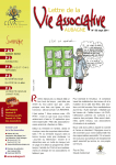
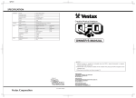
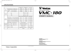
OWNER'S MANUAL
CONGRATULATIONS!
Thank you for purchasing the Vestax PMC-500 Professional Mixing Controller. We suggest that
you read through this owner's manual thoroughly so that you may enjoy the full use of this
product safely and in the knowledge of all its special features and suitable applications.
CONTENTS
C A U T I O N
INPORTANT SAFEGUARDS
SPECIFICATIONS
F E AT U R E S
FUNCTIONS
PROGRAM INPUT SECTION
CROSSFADER SECTION
MONITOR SECTION
MASTER SECTION
R E A R PA N E L
HOW TO CHANGE THE FADER UNIT
BLOCK DIAGRAM
2
3
4
5
5
6
7
7
8
9
11
13
CAUTION
RISK OF ELECTRIC SHOCK DO NOT OPEN
CAUTl0N:TO REDUCE THE RlSK OF ELECTRlC SHOCK
DO NOT REMOVE COVER(OR BACK)
NO USER-SERVICEABLE PARTS INSIDE
REFER SERVlCING T0 QUALIFIED SERVlCE PERSONNEL
The lightning flash with arrowhead symbol,within an equilateral triangle,is intended to
alert the user to the presence of uninsulated“dangerous voltage”within the product's
enclosure that may be of sufficient magnitude to consitute a risk of electric shock to persons.
The exclamation point within an equilateral triangle is intended to alert the user to the presence
of important operating and maintenance(servicing)instructions in the literature accompanying
the appliance.
T0 REDUCE THE RISK 0F FIRE 0R ELECTRlC SHOCK,DO NOT
EXPOSE THIS APPLIANCE T0 RAIN 0R M0ISTURE.
2
IMPORTANT SAFEGUARDS
READ BEFORE OPERATING EQUIPMENT
This product was designed and manufactured to meet
strict quality and safety standards. There are, however,
some installation and operation precautions which you
should be particularly aware of.
1. Read instructions-All the safety and operating
instructions should be read before the appliance
is operated.
2. Retain instructions-The safety and operating
instructions should be retained for future
reference.
3. Heed Warnings-All warnings on the appliance
and in the operating instructions should be
adhered to.
4. Follow Instructions-All operating and use
instructions should be followed.
5. Cleaning-Do not use liquid cleaners or aerosol
cleaners. Use a damp cloth for cleaning.
6. Attachments-Do not use attachments not
recommended by the product manufacturer as
they may cause hazards.
7. Water and Moisture-Do not use this product near
water-for example, near a dath tub, wash bowl,
kitchen sink, or laundry tub, in a wet basement,
or near a swimming pool, and the like.
8. Accessories-Do not place this product on an
unstable cart, stand, tripod, or table. The product
may fall, causing serious injury to a child or
adult, and serious damage to the appliance. Use
only with a cart,. stand, tripod, bracket, or table
recommended by the manufacturer, or sold with
product. Any mounting of the appliance should
follow the manufacturer's instructions, and
sholud use a mounting accessory recommended
by the manufacturer.
9. This product should never be placed near or over
a radiator or heat register. This product should
not be placed in a built-in installation such as a
bookcase or rack unless proper ventilation is
provided or the manufacturer's instructions have
been adhered to.
10. Power sources-This product should be operated
only from the type of power source indicated on
the marking label. If you are not sure of the type
of power supply to your home, consult your
appliance dealer or local power company.
11. Lightning-For added protection for this product
during lightning storm, or when it is left
unattended and unused for long periods of time,
unplug it from the wall outlet. This will prevent
damage to the product due to lightning and
power-line surges.
12. Overloading-Do not overload wall outlets and
extension cords as this can result in a risk of fire
or electric shock.
13. Object and Liquid Entry-Never push objects of
any kind into this product through openings as
they may touch dangerous voltage points or
short-out parts that could result in a fire or
electric shock. Never spill liquid of any kind on
the product.
14. Servicing-Do not attempt to service product
yourself as opening or removing covers may
expose you to dangerrous voltage or other
hazards. Refer all servicing to qualified
sersonnel.
3
15. Damage Requiring Service-Unplug this product
from the wall outlet and refer servicing to
qualified service personnel under the following
conditions:
a. When the power-supply cord or plug is
damaged.
b. If liquid has been spilled or objects have fallen
into the product.
c. If the product has been exposed to rain or
water.
d. If the product dose not operate normally by
following the operating instructions. Adjust
only those controls that are coverd by the
operating instructions as an improper
adjustment of other, controls may result in
damage and will often require extensive work
by a qualified technician to restore the product
to its normal operation.
e. If the product has been dropped or cabinet has
been damaged.
f. When the product exhibits a distinct change in
perfromance-this indicates need for service.
16. Replacement Parts-When replacement parts are
required, be sure the service technician has used
replacement parts specified by the manufacturer
or have the same characterristics as the original
parts. Unauthorized substitutions may result in
fire, electric shock or other hazards.
17. Safety Check-Upon completion of any service or
repairs to product, ask the service technician to
perfrom sefety checks to determine that the
product is in proper operating condition.
18. Carts and Stands-The appliance should be used
only with a cart stand that is recommended by
manufacturer.
19. An appliance and cart combination should be
moved with care. Quick stops, excessive force,
and uneven surfaces may cause the appliance
and cart combination to overturn.
SPECIFICATION
INPUT
SECTION
NOMINAL INPUT
MAXMUM INPUT
INPEDANCE
MIC1
(XLR FEMALE 2PIN HOT BALANCE)
-50dBv
-20dBv
3.3kΩ
MIC2
(1/4 INCH PHONE JACK)
-50dBv
-20dBv
3.3kΩ
1∼5L/R(RCA PIN JACK)
-46dBv
-18dBv
57kΩ
LINE
PHONO
1∼12L/R(RCA PIN JACK)
-10dBv
+8dBv
17kΩ
AUX RCV
(1/4 INCH PHONE JACK)
-10dBv
+12dBv
47kΩ
RATED OUTPUT
MAXMUM OUTPUT
INPEDANCE
MASTER1/2 L/R (XLR MALE 2PIN, BALANCE)
-6dB
+27dB
600Ω OVER/440Ω
MASTER1/2 L/R(1/4 INCH PHONE JACK,UNBALANCE)
0dB, -10dB
+22dB
600Ω OVER/440Ω
-10dB
+13dB
750Ω
0dB∼-10dB
+22dB
10kΩ OVER/220Ω
0dB
+22dB
220Ω
190mW
8Ω OVER/68Ω
OUTPUT
REC OUT
SECTION
BOOTH L/R
(1/4 INCH PHONE OUT)
AUX SEND L/R (1/4 INCH PHONE JACK)
HEAD PHONE (1/4 INCH PHONE JACK)
FREQUENCY
MIC
30Hz ∼ 20kHz ±3dB
CROSSFADER CROSSTALK
RESPONSE
> 80dB
LINE
30Hz ∼ 20kHz ±1.5dB
CHANNEL CROSSTALK
> 65dB
MIC
> 60dB
POWER SUPPLY
AC 100V 50/60Hz 50W
LINE
> 75dB
S/N RATIO
FADER
ATTENUATION
DIMENSION(W×H×D) > 80dB
WEIGHT
4
482×308×142
7kg
FEATURES
・The PMC-500 has Five (5) dedicated line
channels, each with a three (3) band isolator (HI,
MID, LOW), seven (7) segment level indicator,
numerous input options, great effects controls and
super smooth 60mm tight torque rail slide fader.
・Two (2) dedicated MIC channels, which can also be
used as line channels. The main MIC channel has a
XLR input whilst MIC 2 has an unbalanced (1/4)
jack input. Both MIC 1 & 2 have MIC effect loop
inputs (1/4) and two (2) band EQ (HI, LOW).
Both channels are also switch able to line
channels with a LED indicating which channel is
active
・Quality Vestax PCV cross fader (user
replaceable) with four pre-selectable cross fader
curve settings for long or short mixing (scratching
and cutting).
・Flexible Auxiliary (AUX) Send and Receive
(RCV) controls, both with volume level controls.
AUX SEND is pre selectable to Pre, off or post
with its own CUE switch. The AUX RCV has a
seven (7) segment LED for active level metering.
・Full Master and Booth controls. Both Master 1 & 2
and booth outputs are limitable. The attenuation
switch is located under the top panel and pre
selectable to -10dB or 0dB. The BOOTH level
also has a dedicated two (2) band EQ for accurate
monitoring and a BOOTH mute (100%) switch.
・Advanced monitoring and headphone controls
with dedicated two (2) band EQ (HI, LOW). The
headphone signal is selectable to SPLIT CUE or
STEREO CUE.
・Fire Alarm, MUTE function
・High power AC-20 Adapter (+20/-20v, 1500mA).
FUNCTIONS
INPUT SECTION
MASTER SECTION
CROSS FADER SECTION
5
MONITOR SECTION
PROGRAM INPUT SECTION
17
NOTE
8
PGM levels are pre-set for MM type (pick up)
cartridges. When MC type (pick up) cartridges
are used, a head amplifier is required.
1
9
oPGM TRIM
10
2
Adjusts the input level of each PGM channels. For
acoustic clarity, set the INPUT FADER and
MASRER FADER to a position of 7-8. Then adjusts
the INPUT LEVEL METER !7 so as to established
an indicated level of about 0dB.
11
3
4
5
6
7
12
13
15
16
!0 PGM ISOLATOR HI
14
Adjusts the HI frequency level of each PGM.
!1 ISOLATOR MID
18
Adjusts the MID frequency level of each PGM.
!2 PGM ISOLATOR LOW
Adjusts the LOW frequency level of each PGM.
qLINE INPUT RCA JACK
!3 AUX SEND SWITCH
Input connectors for line level equipment such as CD
players, MD players, tape decks, DAT and VTR etc.
This switch enables the signal from each program to be
sent to AUX SEND JACK $9. This signal can be sent to
the AUX device in the following three (3) ways;
PRE: The signal before the input fader (after EQ) will be
sent to AUX SEND JACK.
POST: The signal after the input fader and crossfader will
be sent to AUX SEND JACK.
OFF: No signal will be sent to AUX SEND JACK.
wMIC EQ (HI/LOW)
Adjusts the HI and LOW frequencies for the MIC
input.
eMIC LEVEL
Adjusts the input level of the MIC input.
rMIC/LINE SELECT SWITCH
!4 C.F. ASSIGN SWITCH
Selects between MIC and LINE input.
Assigns the signals from each of the PGM channels to
either side of the crossfader or to MASTER OUT. There
are three positions;
A ……………The PGM is sent to the "A" position or left
position of the crossfader.
MASTER ……The PGM is sent directly to the master out.
B ……………The PGM is sent to the "B" position or
right side of the crossfader.
tMIC/LINE CUE LED
When MIC is selected this LED will be illuminated.
yMIC/LINE CUE ON/OFF SWITCH
Sends the signal from the mic channel to the monitor
section for headphone monitoring.
uMIC/LINE CUE LED
When CUE is selected this LED will be illuminated.
!5 CUE ON/OFF SWITCH
iINPUT SELECT SWITCH
Sends a signal from each PGM to the monitor section for
Selects the input to be sent to each PGM channel. On
headphone monitoring.
the five (5) main PGMs you can select from up to three !6 CUE LED
(3) input sources as follows.
This LED will be illuminated when the CUE
PGM-1 …………PHONO1/LINE1/LINE2
SWITCH !5 is on.
PGM-2 …………PHONO2/LINE3/LINE4
!7
INPUT LEVEL METER
PGM-3 …………PHONO3/LINE5/LINE6
The
LED bar level meters indicate the L and R outputs.
PGM-4 …………PHONO4/LINE7/LINE8
PGM-5 …………PHONO5/LINE9/LINE10
!8 INPUT FADER
All phono inputs are RIAA equalized. The line inputs
Adjusts the Input level of each program. Typically this
can be assigned to either a CD player, MD player, DAT
fader is set to a position of 7-8. This fader is user
player, tape deck or other like LINE device.
replaceable and may be changed easily by following this
users guide's instructions carefully.
See "HOW TO CHANGE THE INPUT FADER UNIT".
*Replace this fader with a Vestax IF-500 replacement
inputfader.
6
CROSS FADER SECTION
!9 CROSS FADER
Mixes the signals assigned by the C.F. ASSIGN
SWITCH !4 to either side of the crossfader. When the
crossfader is set in the center position, both the left and
right signals will be heard. This fader is user replaceable
and may be changed easily by following this user
guide's instructions carefully. See"HOW TO CHANGE
THE CROSSFADER".
*Replace this fader with a Vestax CF-PCV
replacement inputfader.
20
@0 C.F. CURVE SELECT SWITCH
Adjusts the crossfader curve. A clockwise rotation
gives a gentle crossfade, good for long running
mixes, whereas a counter clockwise rotation gives a
sleep crossfade which is good for scratching and
cutting.
19
MONITOR SECTION
@3 MONITOR MODE SELECT SWITCH
When this switch is set to "SPLIT", the master signal
is always heard through the right ear-cup with the
"monitor" PGM being heard in the left ear-cup. The
monitor PGM sent the headphone is controlled
through the MONITOR MODE SELECT SWITCH.
When set to "STEREO" no master output is heard in
the headphones, and only the signal selected by
MONITOR SELECT SWITCH will be heard in both
ear-cups.
21
22
@4 MONITOR MODE LED
This LED will be illuminated when the MONITOR
MODE SELECT SWITCH@3 is on.
24
23
@5 PHONES JACK
Use this jack to connect headphones. Headphones
with an impedance of 8ohm to 600ohm can be used
on this unit.
*For best sound quality Vestax recommends using
Headphones with 150ohm impedance.
25
@1 MONITOR EQ (HI/LOW)
Adjusts the HI and LOW frequencies for Headphone
monitoring.
@2 MONITOR LEVEL
Adjusts the headphone monitor level.
7
MASTER SECTION
#1 METER ASSIGN SWITCH
Use this switch to select either MASTER OUT 1 or
2 to be shown in the MASTER LEVEL METER #0.
#2 POWER LED
This LED will be illuminated when the POWER
SWITCH %4 is on.
#3 AUX SEND LEVEL
Adjusts the output level sent to an external effects unit
connected to the AUX SEND JACK $9 on the rear
panel. When the crossfader is used, this signal is taken
after the crossfader but before the master fader. This
makes a variety of techniques possible, such as the
application of echo to a cut out in which the crossfader
would be used.
#4 AUX RCV LEVEL
Adjusts the input level from an external effect unit
connected to the AUX RCV JACK %0 on the rear
panel.
#5 AUX CUE ON/OFF SWITCH
Sends the signal of external effects unit connected to
the AUX SEND JACK to the MONITOR section for
headphone monitoring.
#6 AUX CUE LED
This LED will be illuminated when the AUX CUE
SWITCH#5 is on.
#7 AUX RCV LEVEL METER
This LED bar level meter indicates the level of the
AUX RCV JACK signal.
#8 BOOTH OUT EQ (HI/LOW)
@6 MASTER BALANCE 1&2
Adjusts the HI and LOW frequencies for the
Adjusts the signal balance of the L to R side of the
BOOTH OUT.
outputs from MASTER OUT 1&2 JACKS %2 on the #9 BOOTH OUT LEVEL
rear panel.
Adjusts the output level of BOOTH OUT.
@7 MASTER LEVEL 1&2
$0 MUTE SWITCH
Adjusts the signal level outputs from MASTER OUT
1&2 JACKS on the rear panel.
This switch mutes the signal being sent to BOOTH
OUT.
@8 MASTER 1&2 CUE SWITCH
$1 MUTE LED
Used to send the signal from the MASTER OUT
1&2 to the monitor section for headphone
monitoring.
This LED will be illuminated when the MUTE
SWITCH $0 is on.
$2MASTER 1&2 & BOOTH OUTPUT LEVEL
SELECTOR (ATTENUATION).
@9 MASTER 1&2 CUE LED
This LED is illuminated when the MASTER 1&2
CUE SWITCH @8 is on.
Located under the top panel, this switch adjusts the
output level for Master 1&2 in addition to the Booth out
put level. The PMC-500 is pre-set to a 0dB output
level but may be changed to -10dB.
#0 MASTER LEVEL METER
This LED bar level meter indicates the L and R
outputs.
8
REAR PANEL
54
52
51
46
45
43
56
44
55
53
50
$3 MIC1 INPUT JACK
47
Connects to the input jack of any recording device
IE, tape recorder, MD, DAT, etc. The output level of
this jack is fixed and does not change with the
MASTER LEVEL.
$4 EFFECT LOOP JACK
%2MASTER OUT1&2(1/4" PHONE JACK
(UNBALANCED),XLR JACK(BALANCED)
TIP: SEND OUT
RING: RETURN INPUT
SLEEVE: EARTH
Connects to the input of an external effects device.
RETURN
49
%1 REC OUT JACK
Input jack for MIC.
MIC1: PHONE JACK (UNBALANCED)
MIC2: XLR JACK (BALANCED)
SEND
48
Connect to the input on a power amplifier. These jacks are
Phone type for consumer applications. This mixer has
two sets of MASTER OUT jacks so that the each output
level can be set separately. Therefore, the MASTER
OUT can be used for main output or sub output IE. One
for the main area and the other for entrance.
EARTH
%3 BOOTH OUT(1/4" PHONE JACK
(UNBALANCED),XLR JACK(BALANCED)
Connects to the DJ booth monitors.
$5 INPUT LEVEL SELECT SWITCH (0dB/-10dB)
Selects the attenuation level for any input signal.
$6 LINE INPUT RCA JACK
Input connectors for line level equipment such as CD
players, MD players, tape decks, DAT and/or VTR
etc.
$7 PHONO INPUT RCA JACK
Input jacks for turntables. Connect turntables
equipped with MM (pick up) cartridge.
$8 GND TERMINAL
In order to prevent feedback from booth monitors
in a typical setting, both MIC1/LINE11 &
MIC2/LINE12 cannot be heard thorough the
booth monitor section. These 2 PGMs can
however be monitored through the headphone
section. An internal modification is needed in
order to allow these a PGMs to be heard through
the booth monitor section. Please consult a
Vestax Technical Support Representative before
attempting any such modification.
Connect this terminal to the ground lead of the
turntable. This will help to reduce unnecessary noise. %4 POWER SWITCH
$9 AUX SEND JACK
Power on/off.
Connects to the input of external effects devices. %5POWER JACK
(Delay, Reverb, etc)
Connect the Vestax AC-20 , AC adaptor.
%0 AUX RCV JACK
Connects to the output of external effects devices.
9
%4 FIRE EVACUATION CONTROL (JACK)
This feature has been added in order to ensure that
venues using the PMC-500 are in compliance with
modern fire safety standards. If a Fire Alarm is
correctly connected to the PMC-500 and is triggered
in an evacuation emergency, the PMC-500 will react
to such a signal (alarm) by swiftly canceling the
output of all but the MIC signal(s). Keeping the MIC
signal(s) open will thus allow the PMC-500 operator
to broadcast any necessary evacuation procedures
ensuring that all present are quickly and safely
notified in an emergency.
Connection to the Fire Evacuation Control Jack can be accomplished as illustrated.
FIRE EVACUATION
CONTROL INPUT JACK
+
−
+ voltage
- voltage
FIRE ALARM
EARTH(GND)
(VENUE)
When a signal of greater than -20dB is sent through the Fire Evacuation Control
Jack to the PMC-500, both the Master Out and Booth Out volume levels (excepting
MIC) will automatically decrease to -18dB, thereby facilitating the broadcast of any
emergency information clearly.
FIRE EVACUATION CONTROL INPUT LEVEL
(INNER OF THE PANEL)
+
BOTTOM PANEL
Professional installation users may wish to alter the sound output level further. In
order to do so please make any such adjustment by using the Fire Evacuation
Control Trim (screw) located on the bottom panel of the PMC-500. (This screw is
located next to the left leg stand).
10
HOW TO CHANGE THE INPUTFADER UNIT
■Change to "IF-500"
q Re1.Remove the fader knobs. (See fig-a)
w Remove the 4 screws which fix the input fader panel to
the mixer. (See fig-b)
e Remove the 2 screws which fix the input fader.
(See fig-c)
r Remove the input fader, and carefully remove the
multi-cable connector from the fader unit.
(See fig-d)
t Replace the fader unit making sure that the connector
wires are securely fastened before carefully
positioning the fader unit and affixing with screws.
fig-b
fig-a
fig-c
fig-d
11
HOW TO CHANGE THE CROSSFADER UNIT
■Change to "CF-PCV"
q Remove the fader knob and 3 screws which fix the
crossfader panel, and the carefully remove the panel.
(See fig-e)
w Remove the 2 screws affixing the crossfader unit.
(See fig-f)
e Carefully remove the multi-cable connector from the
fader unit.
(See fig-g)
r Remove the fader knob of the new CF-PCV.
(See fig-h)
t Replace the fader unit making sure that the connector
wires are securely fastened before carefully
positioning the fader unit and affixing with screws.
fig-e
fig-f
fig-g
fig-h
↑
Set side switch to "PMC" position
12
BLOCK DIAGRAM
13
14
AUG.2003 PMC-500Eq
Vestax Corporation