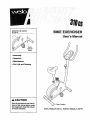
1
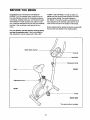
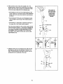
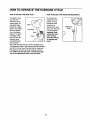
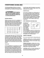
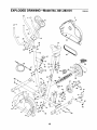
Model No. 831.283101
Serial No.
BIKE EXERCISER
User's Manual
Serial
Number
Decal
• Assembly
• Operation
• Maintenance
• Part List and Drawing
_k CAUTION
Read all precautions and instructions in this manual before using
this equipment. Keep this manual
for future reference.
Patent Pending
Sears, Roebuck and Co., Hoffman Estates, IL 60179
TABLE OF CONTENTS
IMPORTANT PRECAUTIONS ................................................................
BEFORE YOU BEGIN ......................................................................
ASSEMBLY ...............................................................................
HOW TO OPERATE THE EXERCISE CYCLE ....................................................
MAINTENANCE AND TROUBLESHOOTING ...................................................
CONDITIONING GUIDELINES ...............................................................
PART LIST ..............................................................................
EXPLODED DRAWING ....................................................................
ORDERING REPLACEMENT PARTS ..................................................
LIMITED WARRANTY ..............................................................
2
3
4
8
10
12
14
15
Back Cover
Back Cover
IMPORTANT PRECAUTIONS
WARNING:
TO reduce the dsk of serious injury, read the following important precautions before using the exercise cycle.
1. Read all instructions in this manual before
using the exercise cycle.
2. Use the exercise cycle only as described in
this manual.
3. It is the responsibility of the owner to ensure
that all users of the exercise cycle are adequately informed of all precautions.
4,
Use the exercise cycle indoors on a level surface. Keep the exercise cycle away from
moisture and dust. Place a mat under the
exercise cycle to protect the floor.
5. Inspect and properly tighten all parts regularly. Replace any worn parts immediately.
6. Keep children under the age of 12 and pets
away from the exercise cycle at all times.
WARNIN G:
7. Wear appropriate clothes when exercising; do
not wear loose clothes that could become
caught on the exercise cycle. Always wear
athletic shoes for foot protection.
8. The exercise cycle should not be used by
persons weighing more than 250 pounds.
9. Always keep your back straight while using
the exercise cycle; do not arch your back.
10. If you feel pain or dizziness while exercising,
stop ..........
and cool down.
11. The exercise cycle does not have a free
wheel; the pedals will continue to move until
the flywheel stops.
12. The exercise cycle is intended for home use
only. Do not use the exercise cycle in
a commercial,
rental, or institutional setting.
Before beginning this or any exercise program, consult your physician. This
is especially important for persons over the age of 35 or persons with pre-existing health problems.
Read all instructions before using. SEARS assumes no responsibility for personal injury or property
damage sustained by or through the use of this product.
BEFORE YOU BEGIN
Congratulations for selecting the new WESLO °
PURSUIT 310 CS exercise cycle. Cycling is one of
the most effective exercises for increasing cardiovascular fitness, building endurance, and toning the body.
The PURSUIT 310 CS exercise cycle offers a selection of features designed to let you enjoy this healthful
exercise in the convenience and privacy of your
home.
HOME ®(1-800-469-4663). To help us assist you,
please note the product model number and serial
number before calling. The model number is
831.283101. The serial number can be found on a
decal attached to the exercise cycle (see the front
cover of this manual for the location of the decal).
Before reading further, please familiarize yourself with
the parts that are labeled in the drawing below.
For your benefit, read this manual carefully before
you use the exercise cycle. If you have questions
after reading the manual, please call 1-800-4-MY-
Water Bottle Holder*
Console
Handlebar
Resistance Knob
Seat
FRONT
Adjustment Knob
REAR
Pedal
RIGHT SIDE
*No water bottle is included
3
ASSEMBLY
Assembly requires two persons. Place all parts of the exercise cycle in a cleared area and remove the packing
materials. Do not dispose of the packing materials until assembly is completed.
Assembly requires the included tools and your own adjustable wrench _,
driver _Y,,..-,,.=,--,
and pliers _.
Phillips screw-
Use the part drawings below to identifythe small parts used in assembly. The number in parenthesis below
each drawing refers to the key number of the part, from the PART LIST on page 14. The second number refers
to the quantity needed for assembly. Note: Some small parts may have been pre-attached for shipping. If a
part is not in the parts bag, check to see if it has been pre-attached.
Note: If a part is not in the parts bag, first check to see if it has been pre-assembled. If a part is missing,
call toll-free 1-800-999-3756.
M8 Split
Washer (42)-10
M4 x 16mm
Screw (49)-4
M8 Nylon
Locknut (10)-4
M8 x 15mm Button
Screw (34)-6
M10 Nylon
Locknut (33)-4
M10 x 65mm Carriage Bolt (30)-4
1. While another person lifts the front of the Frame (1)
slightly, attach a Stabilizer (2) with two MIO x 65ram
Carriage Bolts (30) and two MIO Nylon Locknuts (33).
3O
2. While another person lifts the rear of the Frame (1)
slightly, attach a Stabilizer (2) with two MIO x 65mm
Carriage Bolts (30) and two MIO Nylon Locknuts (33).
33
2
33
3O
4
3. The Console (16) requires three AA batteries; alkaline
batteries are recommended. Insert three batteries into
the battery compartment. Make sure that the batteries are oriented as shown by the markings inside
the battery compartment.
Batteries
J
16
4. Hold the Console (16) near the Handlebar (15). Insert
the console wire into the indicated hole in the
4
16
Handlebar. Note: The console wire is longer than
shown.
Attach the Console (16) to the Handlebar (15) with four
M4 x 16mm Screws (49). Be careful to avoid pinching the console wire,
Wire
49
5. While another person holds the Handlebar (15) near
the Upright (13), insert the console wire down through
the Upright. Attach the Handlebar te the Upright with
three M8 x 15ram Button Screws (34) and three M8
Split Washers (42). Be careful to avoid pinching the
console wire. Note: The console wire is longer than
shown,
is I
Be careful to
avoid pinching
the console wire.
5
Be careful
to avoid
pinching the
console
wire.
6. While another person holds the Upright (13) in the
position shown, connect the console wire to the Reed
Switch Wire (43). Next, connect the Resistance Cable
(19) to the Lower Cable (45) in the following way:
Be careful to
avoid pinching
the wires and
cables while
inserting the
• See drawing A. Pull up on the metal bracket on the
Lower Cable (45), and insert the tip of the Resistance
Cable (19) into the wire clip inside the metal bracket
as shown.
• See drawing B. Firmly pull up the ResistanceCable
(19) and slide it into the top of the metal bracket as
shown.
/_
Upright.
- _13
• See drawing C. Using pliers, squeeze the prongs on
the upper end of the metal bracket together.
_r-
Console Wire
19/!ii
Push the excess Cable (19, 45) and the excess console
wire down into the Frame (1), and insertthe Upright into
the Frame. Be careful to avoid pinching the Wires
and Cables. Attach the Upright to the Frame with
three M8 x 15mm Button Screws (34) and three M8
Split Washers (42).
=_
_
43
r
34
i _ _- 1
A
B
C
ii
.-..i
-_-_-JMetal
racket
i
19
Metal..
Bracket
P
i
r-
7. Attach the Seat (12) to the Seat Post (5) with four M8
Split Washers (42) and four M8 Nylon Locknuts (10).
Note: The Split Washers and Nylon Locknuts may be
preattached to the underside of the Seat.
42 /s
6
8. Turn the indicated Adjustment Knob (9) counterclockwise and remove it. Insert the Seat Post (5) intothe
Frame (1). Align one of the adjustment holes in the
Seat Post with the indicated hole in the Frame. Insert
the Adjustment Knob into the Frame and the Seat Post,
and turn the Knob clockwise until it is tight. Make sure
that the Knob is inserted through one of the
adjustment holes in the Seat Post.
5
/
/
/
/
/
/
9. Identify the Left Pedal (24), which is marked with an
"L." Using an adjustable wrench, firmly tighten the
Left Pedal counterclockwise into the left arm of the
Crank (21). Tighten the Right Pedal (not shown) clockwise into the right arm of the Crank. Important:
Tighten both Pedals as firmly as possible. After
using the exercise cycle for one week, retighten the
Pedals. For best performance, the Pedals must be
kept tightened.
1,,
F_'_
_
,_Adjustment
Holes
H°le
9
9
10. Make sure that all parts are properly tightened before you use the exercise cycle. Note: After assembly is
completed, some extra parts may be left over. Place a mat beneath the exercise cycleto protectthe floor.
7
HOW TO OPERATE THE EXERCISE CYCLE
HOW TO ADJUST THE SEAT POST
HOW TO ADJUST THE PEDALING RESISTANCE
For effectiveexercise, the seat
should be at the
proper height. As
Seatyou pedal, there
should be a slight
bend in your knees
Seat
when the pedals
are in the lowest
Hole.
position.To adjust
the height of the
seat, first turn the
indicatedknob
counterclockwise
and remove it.
Next, slide the seat post up or down and align one of
the adjustment holes in the seat post with the indicated
hole in the Frame. Insert the knob into the frame and
the seat post, and turn the knob clockwise until it is
tight. Make sure that the knob is inserted through
one of the adjustment holes in the seat post.
To increase the
resistance of the
pedals, turn the
resistance knob
clockwise;to
decrease the resistance, turn the knob
counterclockwise.
Important: Stop
turning the knob
when turning
becomes difficult,
or damage may
result.
FEATURES
OFTHECONSOLE
2. Select one of the modes:
Theeasy-to-use
consolefeatures
five modes that provide instant exemise feedback during your workouts.
The modes are described below.
Scan modem
When the power
is turned on, the
scan mode will be
selected automatically. A mode indicator will appear
below the word
=SCAN" to show
that the scan
mode is selected,
and a second
Mode Indicators
DISTANCE
mode indicator will show which mode is currently
displayed. Note: If you have selected a different
mode, repeatedly press the Mode button to reselect the scan mode.
Speed, time, distance, or calorie
SCAN
mode--To select
one of these
modes for continuous display,
repeatedly press
the Mode button.
The mode indicators will show
which mode is selected. Make sure there is not a
mode indicator below the word "SCAN."
Speed--This mode displays your pedaling speed, in
miles per hour or kilometers per hour.
"rime--This mode displays the elapsed time. Note: If
you stop pedaling for a few seconds, the time mode
will pause.
Note: The console can display speed and distance in either miles or kilometers, To change
the unit of measurement, press the On/Reset
button for about five seconds. The letters mph or
km/h will appear in the displayto show which unitof
measurement is selected. When the batteriesare
replaced, it may be necessary to reselect the
desired unitof measurement.
Distance---This mode displays the distance you have
pedaled, in miles or kilometers.
Calorie--This mode displays the approximate number
of calories you have burned.
Scan--This mode displays the speed, time, distance,
and calorie modes, for a few seconds each, in a
repeating cycle.
3. To reset the display at any time, press the
On/Reset button.
HOW TO OPERATE THE CONSOLE
4.
Make sure there are batteries in the console (see
BA'I-I'ERY REPLACEMENT on page 10). If there is a
thin sheet of clear plastic on the console, remove it.
Follow the steps below to operate the console.
1. To turn on the power, press the On/Reset button or
begin pedaling. The entire display will briefly
appear; the console will then be ready for use.
9
To turn off the power, simplywait for a few minutes.
The console has an "auto.off" feature. If the
pedals are not moved and the console buttons
are not pressed for a few minutes, the power
will turn off automatically to save the batteries.
MAINTENANCE
AND TROUBLESHOOTING
Inspect and tighten all parts of the exercise cycle regularly.Replace any worn parts immediately.
Next, turn the resistance knob to the lowest setting
With the left side shield removed, locate the Reed
Switch (43). Turn the Crank (21) until the Magnet (38)
is aligned with the Reed Switch. Loosen, but do not
remove, the M4 x 16mm Screw (49). Slide the Reed
Switch slightlycloser to or away from the Magnet.
Retighten the Screw. Turn the Crank for a moment.
Repeat until the console displays correct feedback.
When the Reed Switch is correctly adjusted, reattach
the left side shield and the left pedal.
To clean the exercise cycle, use a damp cloth and a
small amount of mild detergent. Important: To avoid
damage to the console, keep liquids away from
the console and keep the console out of direct
sunlight.
BATTERY REPLACEMENT
If the console display becomes dim, the batteries
should be replaced; most console problems are the
result of low batteries. To replace the batteries, refer
to step 4 on page 5 and remove the console from the
handlebar. Next, refer to step 3 on page 5 and insert
three batteries into the console. Reattach the console
to the handlebar, being careful not to pinch the wires.
HOW TO ADJUST THE REED SWITCH
If the console does not display correct feedback, the
reed switch should be adjusted. In order to adjust the
reed switch, the left side shield must be removed.
Using an adjustable wrench, turn the Left Pedal (24)
clockwise and remove it. Next, remove the five M4 x
25mm Screws (41) and the M4 x 16mm Round Head
Screw (3) from the Left Side Shield (17). Carefully
remove the Left Side Shield.
24
3
41
10
CONDITIONING
GUIDELINES
The following guidelines will help you to plan your
exercise program. Remember that proper nutrition
and adequate rest are essential for successful results.
mum fat burning, adjust the intensity of your exercise
until your heart rate is near the middle number in your
training zone as you exercise.
Aerobic Exercise
WARNING: Before
beginning
If your goal is to strengthenyour cardiovascular system, your exercise must be "aerobic." Aerobic exercise is activity that requires large amounts of oxygen
for prolonged pedods of time. This increases the
demand on the heart to pump bloodto the muscles,
and on the lungs to oxygenate the blood. For aerobic
exercise, adjust the intensity of your exercise until
your heart rate is near the highest number in your
training zone.
this or any exercise program, consult your
physician. This is especially important for
persons over the age of 35 or persons with
pre-existing health problems.
EXERCISE INTENSITY
Whether your goal is to bum fat or to strengthen your
cardiovascular system, the key to achieving the
desired results is to exercise with the proper intensity.
The proper intensity level can be found by using your
heart rate as a guide. The chart below shows recommended heart rates for fat burning, maximum fat
burning, and cardiovascular (aerobic) exercise.
165
155
145
140
130
125
115
145
138
130
125
118
110
103
125
120
115
110
105
95
90
20
30
40
50
60
70
80
HOW TO MEASURE YOUR HEART RATE
To measure your
heart rate, first
exercise for at least
four minutes. Then,
stop exercising and
place two fingers
on your wdst as
shown. Take a sixsecond heartbeat
count, and multiply the result by 10 to find your heart
rate. For example, if your six-second heartbeat count
is 14, your heart rate is 140 beats per minute. (A sixsecond count is used because your heart rate will
drop rapidly when you stop exercising.)
To find the proper heart rate for you, first find your age
at the bottom line of the chart (ages are rounded off to
the nearest ten years). Next, find the three numbers
above your age. The three numbers are your "training
zone." The lowest number is the recommended heart
rate for fat burning;the middle number is the recommended heart rate for maximum fat burning;the highest number is the recommended heart rate for aerobic
exercise.
WORKOUT GUIDELINES
Each workout should include the following three pads:
A warm-up, consisting of 5 to 10 minutes of stretching
and light exercise. A proper warm-up increases your
body temperature, heart rate, and circulationin preparation for exercise.
Training zone exercise, consisting of 20 to 30 minutes of exercisingwith your heart rate in your training
zone. Note: During the first few weeks of your exercise program, do not keep your heart rate in your
training zone for longer than 20 minutes.
Fat Burning
To burn fat effectively, you must exercise at a relatively low intensity level for a sustained period of time.
During the first few minutes of exercise, your body
uses easily accessible carbohydrate calories for energy. Only after the first few minutes of exemise does
your body begin to use stored fat calories for energy.
If your goal is to bum fat, adjust the intensityof your
exemise until your heart rate is near the lowest number in your training zone as you exercise. For maxi-
A cool-down, with 5 to 10 minutes of stretching. This
will increase the flexibility of your muscles and will
help to prevent post-exercise problems.
11
EXERCISE FREQUENCY
workouts.After a few months of regular exercise, you
may complete up to five workouts each week, if
desired. Remember, the key to success is make exercise a regular and enjoyable part of your everyday life.
To maintain or improve your condition,plan three workouts each week, with at least one day of rest between
SUGGESTED STRETCHES
The correct form for several basic stretches is shown at the right.
Move slowly as you stretch--never bounce.
1. Toe Touch Stretch
Stand with your knees bent slightly and slowly bend forward from
your hips. Allow your back and shoulders to relax as you reach
down toward your toes as far as possible. Hold for 15 counts,
then relax. Repeat 3 times. Stretches: Hamstrings, back of knees
and back.
2. Hamstring Stretch
Sit with one leg extended. Bringthe sole of the opposite foot
toward you and rest it against the inner thigh of your extended
leg. Reach toward your toes as far as possible. Hold for 15
counts, then relax. Repeat 3 times for each leg. Stretches:
Hamstrings, lower back and groin.
3. Calf/Achilles Stretch
With one leg in front of the other, reach forward and place your
hands against a wall. Keep your back leg straight and your back
foot flat on the floor. Bend your front leg, lean forward and move
your hips toward the wall. Hold for 15 counts, then relax. Repeat
3 times for each leg. To cause further stretchingof the achilles
tendons, bend your back leg as well. Stretches: Calves, achilles
tendons and ankles.
4. Quadriceps Stretch
With one hand against a wall for balance, reach back and grasp
one foot with your other hand. Bring your heel as close to your
buttocks as possible. Hold for 15 counts, then relax. Repeat 3
times for each leg. Stretches: Quadriceps and hip muscles.
5. Inner Thigh Stretch
Sit with the soles of your feet together and your knees outward.
Pull your feet toward your groin area as far as possible. Hold for
15 counts, then relax. Repeat 3 times. Stretches: Quadriceps and
hip muscles.
12
4
NOTES
13
EXPLODED DRAWINGmModel
Key No. Qty.
1
2
3
4
5
6
7
8
9
10
11
12
13
14
15
16
17
18
19
20
21
22
23
24
25
26
27
1
2
2
4
1
1
2
2
1
7
1
1
1
1
1
1
1
1
1
1
1
1
2
1
1
1
1
Description
No. 831.283101
Key No. Qty.
Frame
Stabilizer
M4 x 16mm Round Head Screw
Stabilizer Endcap
Seat Post
C-Magnet Bracket
Handlebar Endcap
Foam Grip
Adjustment Knob
M8 Nylon Locknut
C-Magnet
Seat
Upright
M8 Washer
Handlebar
Console
Left Side Shield
Right Side Shield
Resistance Control/Cable
Seat Post Bushing
Crank/Pulley
Reed Switch Clamp
M10 Washer
Left Pedal
6000Z Bearing
Right Pedal
Resistance Knob
28
29
30
31
32
33
34
35
36
37
38
39
40
41
42
43
44
45
46
47
48
49
50
51
52
#
#
2
1
4
2
3
4
6
1
1
1
1
1
1
5
10
1
1
1
1
1
1
6
2
1
1
1
2
R0903A
Description
U-bracket
Crank Nut
M10 x 65mm Carriage Bolt
Eyebolt
M6 Nut
M10 Nylon Locknut
M8 x 15mm Button Screw
Belt
M4 x 19mm Screw
Flywheel
Magnet
Flywheel Axle
6200Z Bearing
M4 x 28mm Round Head Screw
M8 Split Washer
Reed Switch/Wire
Crank Bearing Set
Lower Cable
Resistance Cable
Return Spring
Spring
M4 x 16mm Screw
M6 Zinc Nut
M6 x 35mm Bolt
M8mm x 21mm Bolt
User's Manual
Allen Wrench
Note: "#" indicates a non-illustratedpart. Specifications are subject to change without notice. If a part is missing, call toll-free 1-800-999-3756. See the back cover of this manual for informationabout ordering replacement
parts.
14
EXPLODED DRAWING--Model
No. 831.283101
Rogo3A
18
12
42
34
35
26
>34
10
34
44
3O
53
10
3
10
41'
i
17
32
15
38
Get it fixed, at your home or ours!
Your Home
For repatr- in your home - of all major brand appliances, lawn and garden equipment,
or heating and cooling systems, no matter who made it, no matter who sold it!
For the replacement
parts, accessories, and user's manuals that you need to do-it-yourself.
For Sears professional installation of home appliances
and items like garage door openers and water heaters.
1-800-4-MY-HOM E_
_1-800-469-4663)
www.sears.com
Anytime, day or night
(U.S.A.and Canada)
www.sears.ca
Our Home
For repair of carry-in products like vacuums, lawn equipment,
and electronics, call or go on-line for the location of your nearest
Sears Parts and Repair Center.
1-800-488-1222
Anytime, day or night (U.S.A.
only)
www.sears,Gom
To purchase a protection agreement (U.S.A.)
or maintenance agreement (Canada) on a product serviced by Sears:
1-800-827-6655
(U.S._)
1-800-361-6665
(Canada)
Para pedir servicio de reparacion a domicilio, y para ordenar piezas:
1-888-SU-HOGAR s'_ (1-888-784-6427)
SEARS
® Registered Trademark / _ Trademark / su Service Mark of Sears, Roebuck and CO.
® Marca Registrada / TM Marca de F&bdca / SMMarca de Servicio de Sears, Roebuck and Co.
FULL 90 DAY WARRANTY
f
For 90 days from the date of purchase, if failure occurs due to defect in material or workmanship in this
Sears Bike Exerciser, contact the nearest Sears Service Center throughout the United States and
Sears will repair or replace the Bike Exerciser, free of charge.
This warranty does not apply when the Bike Exerciser is used commerciallyor for rental purposes.
This warranty gives you specific legal rights, and you may also have other rights which vary from state
to state.
Sears, Roebuck and Co., Dept. 817WA, Hoffman Estates, IL 60179
Part No. 204487 R0903A
Printed in China © 2003 Sears, Roebuck and Co.