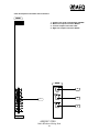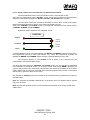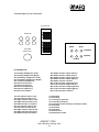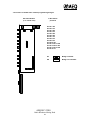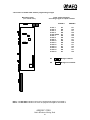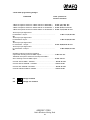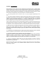
1
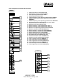
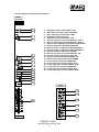
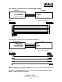
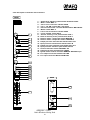
AEQ BC-2500
Broadcast Audio Mixer
USER’S MANUAL
ED. 01/03
A.E.Q., S.A. manufacturer of this equipment is a Registered Company
with UNE EN - ISO-9001 by AENOR ER-080/1/96 standard.
1.
GENERAL
1.1. GENERAL PRECAUTIONS
1.1.1. READ ALL INSTRUCTIONS
1.1.2. POWER SUPPLY AND EARTH CONNECTIONS
1.1.3. PROTECTION FROM EXCESSIVE SUPPLY VOLTAGE VARIATION
1.1.4. PROTECTION AGAINST WATER AND HUMIDITY
1.1.5. VENTILATION, FIRE AND INFLAMMABLE VAPOURS
1.1.6. MAINTENANCE
1.1.7. GUARANTEE
2.
EQUIPMENT POWER SUPPLY
2.1. GENERAL
2.1.1. BEFORE CONNECTION TO THE MAINS SUPPLY
2.1.2. VOLTAGE SELECTION
2.1.3. SWITCHING ON THE EQUIPMENT
3.
AUDIO CONNECTIONS
3.1. GENERAL
3.2. OTHER AUDIO CONNECTIONS
4.
MIXER DESCRIPTION
4.1. BASIC DESIGN CONCEPTS
4.2. INITIAL CONFIGURATION
5.
MODULE DESCRIPTION
5.1. BC-2511 MICRO/LINE MONOPHONIC MODULE
5.1.1.FUNCTIONAL DESCRIPTION
5.1.2. DESCRIPTION OF CONTROLS AND CONNECTORS
5.2. BC-2521 DOUBLE LINE EQUALIZED STEREO MODULE
5.2.1. FUNCTIONAL DESCRIPTION
5.2.2. DESCRIPTION OF CONTROLS AND CONNECTORS
5.3. BC-2522 DOUBLE LINE NOT EQUALIZED STEREO MODULE
5.3.1. FUNCTIONAL DESCRIPTION
5.3.2. DESCRIPTION OF CONTROLS AND CONNECTORS
5.4. BC-2533 HYBRID TELEPHONE INPUT/OUTPUT MODULE
5.4.1. FUNCTIONAL DESCRIPTION
5.4.2. EXAMPLE OF REMOTE CONNECTION OF THE HYBRID AEQ TH-02
MK-II
5.4.3. EXAMPLE OF REMOTE CONNECTION OF THE HYBRID AEQ TH-12
5.4.4. DESCRIPTION OF CONTROLS AND CONNECTORS
5.5. BC-2560-A STEREOPHONIC + SUM MONOPHONIC OUTPUT MODULE
5.5.1. FUNCTIONAL DESCRIPTION
5.5.2. DESCRIPTION OF CONTROLS AND CONNECTORS
5.6. BC-2560-C STEREOPHONIC + SUM MONOPHONIC + INPUT BYPASS
OUTPUT MODULE
5.6.1. FUNCTIONAL DESCRIPTION
AEQ BC-2500
Radio Broadcast Mixing Desk
3
5.6.2. DESCRIPTION OF CONTROLS AND CONNECTORS
5.7. BC-2578 MONITORING, SIGNAL AND CONTROL MODULE
5.7.1. FUNCTIONAL DESCRIPTION
5.7.1.1.CONTROL MONITORS, METERS AND PRE-LISTEN BLOCK
5.7.1.1.1. DESCRIPTION OF CONTROLS
5.7.1.2. STUDIO MONITOR BLOCK
5.7.1.2.1. DESCRIPTION OF CONTROLS
5.7.1.3. COMMAND, INTERCOM, OSCILLATOR AND TIME-SIGNAL
BLOCK
5.7.1.3.1. DESCRIPTION OF CONTROLS
5.7.1.4. STUDIO AND CONTROL MONITOR CUT AND SIGNAL
ADMINISTRATION
5.7.1.5. REMOTE FUNCTIONS
5.7.2. DESCRIPTION OF REAR CONNECTORS
5.8. BC-2523 EXTERNAL POWER SUPPLY MODULE
5.8.1. FUNCTIONAL DESCRIPTION
5.8.2. DESCRIPTION OF CONTROLS AND CONNECTORS
5.9. BC-2501 CHASSIS AND METER PANEL MODULE
5.9.1. FUNCTIONAL DESCRIPTION
6.
TECHNICAL SPECIFICATIONS
6.1INPUTS
6.1.1. MICROPHONE INPUT
6.1.2. LINE INPUTS
6.1.3. BC-2511 INPUT/OUTPUT
6.1.4. BC-2533 HYBRID TELEPHONE INPUT/OUTPUT
6.1.5. BC-2578 EXTERNAL INPUTS
6.1.6. SENDS AND EQUALIZATION
6.1.7. BY-PASS INPUT
6.2. OUTPUTS
6.2.1. BC-2560 A/C MASTER AND AUXILIARY OUTPUTS
6.2.2. CONTROL AND STUDIO MONITOR OUTPUTS
6.2.3. INTERCOM
6.3. SIGNALING
6.4. POWER SUPPLY
6.5. DIMENSIONS
6.5.1. 20/24 MODULES CHASSIS DIAGRAM
AEQ BC-2500
Radio Broadcast Mixing Desk
4
7.
CONFIGURATION OF PROGRAMMABLE BRIDGES
7.1.BC-2511 PROGRAMMING BRIDGES
7.2.POSITION OF THE BC-2511 MODULE PROGRAMMING BRIDGES
7.3.BC-2521/22 PROGRAMMING BRIDGES
7.4. POSITION OF THE BC-2521/22 MODULE PROGRAMMING BRIDGES
7.5. BC-2560 A/C PROGRAMMING BRIDGES
7.6. POSITION OF THE BC-2560 A/C MODULE PROGRAMMING BRIDGES
7.7. BC-2533 PROGRAMMING BRIDGES
7.8. POSITION OF THE BC-2533 MODULE PROGRAMMING BRIDGES
7.9. BC-2578 PROGRAMMING BRIDGES
7.10 POSITION OF THE BC-2578 MODULE PROGRAMMING BRIDGES
APPENDIX 1: AEQ WARRANTY
BLOCK DIAGRAM
AEQ BC-2500
Radio Broadcast Mixing Desk
5
1. GENERAL
1.1. General precautions
The following cautionary and security measures must be observed during all phases of
operation and maintenance of the unit. Failure to follow the instructions that are highlighted in this
manual could affect the specification and function of the equipment. AEQ. S.A. accept no
responsibility for damage or injury caused by incorrect operation of the equipment.
1.1.1. Read all the instructions.
To obtain the optimum performance and reliability from the moment of installation, and to
prevent injury, incorrect operation or damage to the equipment, it is absolutely indispensable to
thoroughly read all the instructions contained in this manual before connecting and operating the
equipment.
1.1.2. Power supply and earth connections.
To reduce the risk of electric shock, the power supply of this unit should be connected to
earth. The equipment is supplied with an earth connection socket. If it is necessary to change the
connection it should be noted that the cable to earth is marked yellow/green.
Note: The console must only be connected to the power supply module with the cable
supplied by the manufactures for this purpose. Cables of greater length may be ordered from the
manufactures if required.
1.1.3. Protection from excessive supply voltage variation.
In areas which are subject to frequent variations in the supply voltage it will be necessary
to incorporate additional external protection for the equipment, to ensure that the equipment
receives the voltage as specified in this manual.
1.1.4. Protection against water and humidity.
This equipment is not recommended for use in areas subject to ingress of rain, water etc.,
or sites with humid floors, or in places that are subject to a high degree of atmospheric humidity
that is condensing.
1.1.5. Ventilation, fire and inflammable vapours.
The equipment must not be place close to a source of heat. The use of electrical or
electronic equipment near a source of fire or in atmosphere containing inflammable vapours is
extremely dangerous and must be avoided at all cost.
All the ventilation grilles must remain unobstructed to permit sufficient ventilation and allow
the dissipation of heat to the exterior of the equipment.
AEQ BC-2500
Radio Broadcast Mixing Desk
6
1.1.6. Maintenance
The maintenance operations of this unit should only be carried out by qualified technical
personnel. AEQ S.A. does not accept responsibility for any damage or injury to the equipment
caused by maintenance by unauthorized persons, not for any damage or injury to other equipment
or persons caused by any unauthorized repair or maintenance operation.
Caution. A risk of severe electrical shock exists due to very high voltages that are
present in the interior of the power supply unit. Therefore proceed with absolute caution when
manipulating this unit.
The AEQ BC-2500 mixing console does not require preliminary adjustment, after
programming has been carried-out as described in this manual either by the maintenance
technician or the manufacturer, no additional operations whatsoever are necessary to obtain
optimum performance.
However it is advisable to periodically desmagnetize the input transformers of the various
modules, due to the influence this factor has on the final distortion ratio of the equipment. This
operation can be performed effectively by applying a 25 Hz signal at a level sufficient to saturate
the transformer core and then slowly diminish the signal level until annulment is achieved. It is
recommended that this operation is performed annually.
Note: In the event that the maintenance technician requires to change the location of the unit or
incorporate new modules in the equipment, the following procedure must be adopted:
1) Turn off the equipment using the on/off switch located at the rear of the power supply
module BC-2523.
2) Proceed to the removal of the module(s) for interchange by removing the chassis fixing
screws located at both end of the panel.
3) Disconnect the internal bus by loosening the ribbon cable connector located in the
lower middle part of the printed circuit board and the rear mounted connectors if fitted.
Module replacement is effected by the direct reversal of the operations described above.
1.1.7.
Guarantee.
Guarantee period: The terms and conditions are as stated in the APPENDIX 1 of this
manual.
AEQ BC-2500
Radio Broadcast Mixing Desk
7
2. EQUIPMENT POWER SUPPLY
2.1. General
A description of the module to power supply connection is detailed in Section 5.7 and 5.8.
2.1.1. Before connection to the mains supply
Caution: Before the equipment is connected to the power supply, the voltage selector
must be checked an if necessary set for the supply voltage as in Section 2.1.2. and the DC power
supply cable connected between module BC-2578 and the power supply BC-2523. The procedures
detailed in this section must be followed carefully before connecting and operating the equipment.
2.1.2. Voltage selection.
The AEQ BC-2500 mixer is designed to operate with a 110/220 V AC power supply. Set
the VOLTAGE SELECTOR (see Section 5.8 of this manual) to appropriate network supply voltage.
If the 110 V AC supply voltage is selected, the fusible link fitted as standard to the
equipment must be replaced by the alternative that can be found in the plastic bag containing this
manual, and following these instructions. Remove the fuseholder located in the rear of the power
supply module BC-2523 (see section 5.8 of this manual), and replace the existing fuse with the
alternative as mentioned previously.
Remember: 220 V AC Power supply = 1.6 A Fuse
110 V AC Power Supply = 2.5 A Fuse
Type T
Type T
Note: The equipment can be supplied with 220 AC or 110 AC volts supply.
Note: The power supply cable is supplied with a European Standard mains
interconnecting plug. In certain countries it could be necessary to exchange this plug to adapt to
the prevailing local standards. If this is the case, the substitution of the plug should be carried-out
before proceeding.
Note: Signallig circuit has its own fuse. This one is a 1 Amp fuse.
2.1.3. Switching on the equipment.
Once the checks and/or modifications indicated in the Section 2.1.2. have been
accomplished the equipment is prepared for connection to the electric supply network. Prior to
connection ensure that power supply switch POWER is in the off position.
Activate the power supply switch POWER. If all the previous instruction have been
correctly followed, the LED’s labelled as +ANALOG and - ANALOG of the control module BC2578 will illuminate, indicating that the equipment is receiving power supply.
Note: For the location of the power switch an LED’s indicators mentioned above, refer to sections
5.7. and 5.8. of this manual.
AEQ BC-2500
Radio Broadcast Mixing Desk
8
3. AUDIO CONNECTIONS
3. 1. General
The audio connections of the AEQ BC-2500 mixer comply with the AES 14-1992 (ANSIS
4.48-1992) recommendations. This recommendation is based on IEC 268-12 of 1987. Equipment
for sound systems part 12, application of connectors for radio broadcast and similar uses.
The audio connection cables should be checked for compatibility with the standards
indicated. If this is not the case they must be exchanged or modified since problems could be
encountered with the phase of the audio signal.
male pin connector
1
equipment output
2
3
female socket
connector
equipment input
PIN NUMBER
Application &
Power Supply
1
Balanced
Mono Channel
Screen
Positive Polarity
Return
Unbalanced
Mono Channel
Screen & Return
Positive Polarity
NOTE 1*
Balanced Mono
Channel.
Phantom Power
Balanced Mono
Channel
Power A-B
Screen & Negative
Power
Screen
2
3
Polarity &Positive Power
Return & Positive Power
Polarity &Positive Power
Return & Negative Power
NOTE 1*
If a balanced
microphone is
connected to an
unbalanced
amplifier
input,the input
contact 3 is
connected to
contact 1.
3. 2. Other audio connections.
The BC-2578 module multipin connector wiring layout is described in section 5.7.2. of this
manual.
The BC-2511 module 1/4” jack connectors are wiring according to the following diagram:
RETURN
SEND
COMMON
AEQ BC-2500
Radio Broadcast Mixing Desk
9
4. MIXER DESCRIPTION
4.1. Basic design concepts.
The AEQ BC-2500 Audio Mixer has been designed for use in radio broadcast studios
together with mobile units, television and sound installations where the quality and reliability of the
equipment are fundamental factors.
The criteria base for development and fabrication of the audio mixer were based on our extensive
experience in the field of radio broadcasting and direct contact with the professionals in the sector.
This has allowed us to capture the necessity of an audio mixer for radio and television in line with
current technology and with the highest performance.
The design and configuration assures rapid assimilation of the mixer functions by the user. The
logical distribution of the controls and the automatic monitor and signal cut features simplify the
operator tasks.
The modular concept allows the extraction of any module for repair or replacement in a
few moments. The high quality of the components used in manufacture guarantees the prolonged
service life of the equipment.
The AEQ BC 2500 audio mixer is user configurable according to the specific
requirements. Beginning with the standard ex-works configuration, it is easily upgraded by
incorporating new input modules or it can be redistributed according to operator preferences.
The following details some of the characteristics that make the AEQ BC 2500 mixer an
excellent piece of equipment for utilization in radio and television broadcasters.
- Programmable micro input channels for autocontrol or announcer control by means of
internal programmable bridges.
- Fader control of VCA signal.
- Indirect control of the principal outputs.
- Electronically balanced buses.
- Transformed balanced inputs and outputs.
- External inputs 1 and 2 Electronically balanced.
- Input channel RF filters.
- Lock-in metal XLR connectors.
- Output to auxiliary programmable pre or post fader by internal bridges.
- Remote Mute and PFL from the announcer.
- Input module saturation and “clipping” indicators.
- Stereo pre-listening.
- Input/output module compatible with an external hybrid telephone, with independent
control and PFL for both input and output.
- Output modules with simultaneous stereophonic/monophonic function.
- Output modules with simultaneous stereophonic/monophonic function with exterior
stereo input which is “bypassable” to the stereo output.
- Independent headphone controls for the controller, the primary and secondary
announcers.
- 4 way intercom for communication of instructions to or from the exterior, co-ordination
of mobile units, microphone lines, etc...
- Automatic signal activation ON AIR through input modules, programmable by
internal bridges.
- 24 volts power supply for signaling.
AEQ BC-2500
Radio Broadcast Mixing Desk
10
4.2. Initial Configuration
The AEQ BC-2500 audio mixer is supplied with two basic configurations:
BC-2500 FM-AUTOCONTROL
1
BC-2501FM
1
BC-2578
2
5
1
2
7
1
BC-2511
BC-2522
BC-2533
BC-2560-A
BC-2502
BC-2523
Chassis with capacity for 24/20 modules, with audio meters and PFL
monitor loudspeakers.
Control, monitor and “intercom” module for controller and announcer.
(occupies three module space)
Micro/line mono input module.
Double switchable stereo input module.
External hybrid telephone input/output and control module.
Stereo plus added mono output module.
Blank module.
External power supply module.
(This module does not occupy chassis space)
BC-2500 FM ANNOUNCER-CONTROL
1
BC-2501FM
1
2
6
2
2
3
1
BC-2578
BC-2511
BC-2522
BC-2533
BC-2560-A
BC-2502
BC-2523
Chassis with capacity for 24/20 modules, with audio meters and PFL
monitor loudspeakers.
Control, monitor and “intercom” module for controller and announcer.
Micro/line mono input module.
Double switchable stereo input module.
External hybrid telephone input/output and control module.
Stereo plus added mono output module.
Blank module. (This module does not occupy chassis space)
External power supply module.
Other configurations are available on demand, only limited by the spatial capacity of the
chassis. The minimum functional requirement is the inclusion of one BC-2501 or BC-2501FM
module, one BC-2578 module, one input and one output module, an external power supply and
blanking plates to complete the chassis.
AEQ BC-2500
Radio Broadcast Mixing Desk
11
5. MODULE DESCRIPTION
5.1. BC-2511 MICRO/LINE MONO INPUT MODULE.
5.1.1. Functional description.
The micro/line mono input module BC-2511 permits the connection of two independent
inputs; one microphone level (21) and the other line level (22), selection being carried-out by
means of the switch (1) MICRO/LINE.
Push-bottom (3) HFF activates a radiofrequency filter. (100 Hz)
Once the input type is selected, the level is adjusted by the potentiometer (2) GAIN, an external
signal can then be introduced through the connector (20) INSERT, subsequently the equalization
can be adjusted by the potentiometers (4, 5, 6 and 7) TREBLE, MID/FREQ, MID/GAIN and
BASS, corresponding to the treble level, mid frequencies gain and bass level respectively,
whenever the equalization circuit is activated by the switch (8) EQ ON.
With the aim of avoiding saturation an LED indicator (9) CLIP illuminates on reaching
maximum signal level. If required this signal can be monitored by activating Push-button (16) PFL
ON, to send it to the pre-listen bus. This status is confirmed by the illumination of led indicator
(17).
Potentiometer (12) BALANCE regulates the left/right channel output signal balance.
The output signal can be directed to the following outputs whenever the operative channel
selector (18) CHANNEL ON is activated:
Master 1, adjusts the send level with fader (19) and pushing the switch (13) MASTER 1
Master 2, adjusts the send level with fader (19) and pushing the switch (14) MASTER 2
Telephone buses 1 and 2, adjust the send level with fader (19) and pushing the switch (15)
PHONE.
This signal can also be sent to the following auxiliary outputs:
Auxiliary 1, the send level is adjusted with potentiometer (10) AUX 1 if working with the Auxiliary 1
send programmed pre-fader or the send level is adjusted with fader (19) once the send level to
Auxiliary bus 1 is set with potentiometer (10) AUX 1 when working with the send to auxiliary 1
programmed as post-fader and whenever the channel operative switch (18) CHANNEL ON is
activated.
Auxiliary 2, the send level is adjusted with potentiometer (11) AUX 2 if working with the Auxiliary 2
send programmed pre-fader or the send level is adjusted with fader (19) once the send level to
Auxiliary bus 1 is set with potentiometer (11) AUX 2 when working with the send to auxiliary 1
programmed as post-fader and whenever the channel operative switch (18) CHANNEL ON is
activated.
The position of the programming bridges and their functions are described in Section 7 of
this manual.
AEQ BC-2500
Radio Broadcast Mixing Desk
12
5.1.2. Description of Controls and Connectors.
FRONT
1
2
3
4
5
6
7
8
9
10
11
12
1.2.3.4.5.-
Input switch MICRO/LINE
Gain adjusting potentiometer GAIN
Radiofrequency switch HFF
Treble frequency level adjusting potentiometer TREBLE
Middle frequency parametric equalizer potentiometer
MID/FREQ
6.- Middle frequency level adjusting potentiometer MID/GAIN
7.- Bass frequency level adjusting potentiometer BASS
8.- Equalizer activation switch EQ.ON
9.- Saturation level led indicator CLIP
10.- Send to auxiliary 1 bus potentiometer AUX. 1
11.- Send to auxiliary 2 bus potentiometer AUX. 2
12.- Balance level adjusting potentiometer BALANCE
13.- Send to master 1 output bus switch MASTER 1
14.- Send to master 2 output bus switch MASTER 2
15.- Send to telephone bus switch PHONE
16.- Send to pre-listen bus push-button PFL ON
17.- Pre-listen active led indicator PFL ON
18.- Channel activation switch CHANNEL ON
19.- Output level slide potentiometer FADER
20.- Input/output connector socket INSERT
21.- Microphone input connector MICRO
22.- Line input connector LINE
13
14
15
16
17
18
REAR
20
19
21
22
AEQ BC-2500
Radio Broadcast Mixing Desk
13
5.2. BC-2521 DOUBLE LINE EQUALIZED STEREO INPUT MODULE.
5.2.1. Functional description
The Double Line Equalized Stereo Input Module BC-2521 permits the connection of two
stereo inputs A and B. These lines are connected to (23) INPUT A (L) and (24) INPUT A (R) for
the left and right Line A channels and (26) INPUT B (L) and (27) INPUT B (R) for the left and rigth
Line B channels, selection is by switch (1) INPUT A/B. If the selector is at rest input A is active,
when the selector is depressed input B is selected.
The gain of the selected input is adjusted with potentiometer (3) GAIN.
It is possible to convert this signal to mono by activating switch (2) ST/MONO
Switch (4) HFF activates a radiofrequency filter. (100 Hz)
Subsequently the equalization can be adjusted by the potentiometers (5, 6, 7 and 8) TREBLE,
MID/FREQ, MID/GAIN & BASS, corresponding to the treble level, mid frequencies, mid
frequencies gain and bass level, respectively, whenever the equalization circuit is activated by the
switch (9) EQ ON.
With the aim of avoiding saturation a led indicator (10) CLIP illuminates on reaching
maximum signal level. If required this signal can be monitored by activating Push-button (18) PFL
ON, to send it to the pre-listen bus. This status is confirmed by the illumination of led indicator
(19).
Potentiometer (12) BALANCE regulates the left/right channel output signal balance. This
function is activated when switch (14) BALANCE ON is activated.
The output signal can be directed to the following outputs whenever the operative switch
(20) CHANNEL ON is activated:
Master 1, adjusts the send level with fader (21) and pushing the switch (15) MASTER 1
Master 2, adjusts the send level with fader (21) and pushing the switch (16) MASTER 2
Telephone buses 1 and 2, adjust the send level with fader (21) and pushing the switch (17)
PHONE.
This signal can also be sent to the following auxiliary outputs:
Auxiliary 1, the send level is adjusted with potentiometer (11) AUX 1 if working with the Auxiliary 1
send programmed pre-fader or the send level is adjusted with fader (21) once the send level to
Auxiliary bus 1 is set with potentiometer (11) AUX 1 when working with the send to auxiliary 1
programmed as post-fader and whenever the channel operative switch (20) CHANNEL ON is
activated.
Auxiliary 2, the send level is adjusted with potentiometer (12) AUX 2 if working with the
Auxiliary 2 send programmed pre-fader or the send level is adjusted with fader (21) once the send
level to Auxiliary bus 1 is set with potentiometer (12) AUX 2 when working with the send to
auxiliary 1 programmed as post-fader and whenever the channel operative switch (20) CHANNEL
ON is activated.
The position of the programming bridges and their functions are described in Section 7 of
this manual.
AEQ BC-2500
Radio Broadcast Mixing Desk
14
5.2.2. Description of Controls and Connectors.
FRONT
1
2
3
4
5
6
7
8
9
10
11
12
13
14
15
16
17
18
19
1.2.3.4.5.6.-
A/B Input selector switch INPUT A/B
Mono/stereo selector switch ST/MONO
Gain adjusting potentiometer GAIN
Radiofrequency switch HFF
Treble frequency level adjusting potentiometer TREBLE
Middle frequency parametric equalizer potentiometer
MID/FREQ
7.- Middle frequency level adjusting potentiometer MID/GAIN
8.- Bass frequency level adjusting potentiometer BASS
9.- Equalizer activation switch EQ.ON
10.- Saturation level led indicator CLIP
11.- Send to auxiliary 1 bus potentiometer AUX. 1
12.- Send to auxiliary 2 bus potentiometer AUX. 2
13.- Balance level adjusting potentiometer BALANCE
14.- Balance activation switch BALANCE ON
15.- Send to master 1 output bus switch MASTER 1
16.- Send to master 2 output bus switch MASTER 2
17.- Send to telephone bus switch PHONE
18.- Send to pre-listen bus push-button PFL ON
19.- Pre-listen active led indicator PFL ON
20.- Channel activation switch CHANNEL ON
21.- Output level slide potentiometer FADER
22.- Line A remote connectors REMOTE A
23.- Line A left input connector INPUT A(L)
24.- Line A rigth input connector INPUT A (R)
25.- Line B remote connectors REMOTE B
26.- Line B left input connector INPUT B (L)
27.- Line B rigth input connector INPUT B (R)
20
REAR
22
23
21
24
25
26
27
AEQ BC-2500
Radio Broadcast Mixing Desk
15
5.3. BC-2522 DOUBLE LINE STEREO INPUT MODULE.
5.3.1. Functional description
The Double Line Stereo Input Module BC-2522 permits the connection of two stereo inputs
A and B. These lines are connected to (18) INPUT A (L) and (19) INPUT A (R) for the left and right
Line A channels and (21) INPUT B (L) and (22) INPUT B (R) for the left and rigth Line B channels,
selection is by switch (1) INPUT A/B. If the selector is at rest input A is active, when the selector
is depressed input B is selected.
The gain of the selected input is adjusted with potentiometer (3) GAIN.
It is possible to convert this signal to mono by activating switch (2) ST/MONO
Switch (4) HFF activates a radiofrequency filter. (100 Hz).
With the aim of avoiding saturation a led indicator (5) CLIP illuminates on reaching
maximum signal level. If required this signal can be monitored by activating Push-button (13) PFL
ON, to send it to the pre-listen bus. This status is confirmed by the illumination of led indicator
(14).
Potentiometer (8) BALANCE regulates the left/right channel output signal balance. This function is
activated when switch (9) BALANCE ON is activated.
The output signal can be directed to the following outputs whenever the operative channel
selector (15) CHANNEL ON is activated:
Master 1, adjusts the send level with fader (16) and pushing the switch (10) MASTER 1
Master 2, adjusts the send level with fader (16) and pushing the switch (11) MASTER 2
Telephone buses 1 and 2, adjust the send level with fader (16) and pushing the switch (12)
PHONE.
This signal can also be sent to the following auxiliary outputs:
Auxiliary 1, the send level is adjusted with potentiometer (6) AUX 1 if working with the Auxiliary 1
send programmed pre-fader or the send level is adjusted with fader (16) once the send level to
Auxiliary bus 1 is set with potentiometer (6) AUX 1 when working with the send to auxiliary 1
programmed as post-fader and whenever the channel operative selector (15) CHANNEL ON is
activated.
Auxiliary 2, the send level is adjusted with potentiometer (7) AUX 2 if working with the Auxiliary 2
send programmed pre-fader or the send level is adjusted with fader (16) once the send level to
Auxiliary bus 1 is set with potentiometer (7) AUX 2 when working with the send to auxiliary 1
programmed as post-fader and whenever the channel operative switch (15) CHANNEL ON is
activated.
The position of the programming bridges and their functions are described in Section 7 of
this manual.
AEQ BC-2500
Radio Broadcast Mixing Desk
16
5.3.2. Description of Controls and Connectors.
FRONT
1
2
3
4
5
6
7
8
9
10
11
12
13
14
1.- A/B Input selector switch INPUT A/B
2.- Mono/stereo selector switch ST/MONO
3.- Gain adjusting potentiometer GAIN
4.- Radiofrequency switch HFF
5.- Saturation level led indicator CLIP
6.- Send to auxiliary 1 bus potentiometer AUX. 1
7.- Send to auxiliary 2 bus potentiometer AUX. 2
8.- Balance level adjusting potentiometer BALANCE
9.- Balance activation switch BALANCE ON
10.- Send to master 1 output bus switch MASTER 1
11.- Send to master 2 output bus switch MASTER 2
12.- Send to telephone bus switch PHONE
13.- Send to pre-listen bus push-button PFL ON
14.- Pre-listen active led indicator PFL ON
15.- Channel activation switch CHANNEL ON
16.- Output level slide potentiometer FADER
17.- Line A remote connectors REMOTE A
18.- Line A left input connector INPUT A (L)
19.- Line A rigth input connector INPUT A (R)
20.- Line B remote connectors REMOTE B
21.- Line B left input connector INPUT B (L)
22.- Line B rigth input connector INPUT B (R)
15
REAR
17
18
19
16
20
21
22
AEQ BC-2500
Radio Broadcast Mixing Desk
17
5.4. BC-2533 HYBRID TELEPHONE INPUT/OUTPUT MODULE.
5.4.1. Functional description
The Hybrid Telephone Input/Output Module BC-2533 permits the adaptation of an external
analogue or digital hybrid telephone to the other modules that make up the system.
An audio input (20) INPUT FROM LINE is available for the signal from the external hybrid
telephone at line level. This input can be monitored by activating the push-button PFL INPUT (16)
the status is shown by the illumination of the PFL led. PFL INPUT (14).
The output signal can be directed to the following outputs whenever the operative channel
selector (17) CHANNEL ON is activated:
Master 1, adjusts the send level with fader (18) and pushing the switch (11) MASTER 1
Master 2, adjusts the send level with fader (18) and pushing the switch (12) MASTER 2
Auxiliary 1, the send level is adjusted with potentiometer (9) AUX 1 if working with the Auxiliary 1
send programmed pre-fader or the send level is adjusted with fader (18) once the send level to
Auxiliary bus 1 is set with potentiometer (9) AUX 1 when working with the send to auxiliary 1
programmed as post-fader and whenever the channel operative switch (17) CHANNEL ON is
activated.
Auxiliary 2, the send level is adjusted with potentiometer (10) AUX 2 if working with the Auxiliary 2
send programmed pre-fader or the send level is adjusted with fader (18) once the send level to
Auxiliary bus 1 is set with potentiometer (10) AUX 2 when working with the send to auxiliary 1
programmed as post-fader and whenever the channel operative switch (17) CHANNEL ON is
activated.
Press button (5) MULTIPLEX. When this function is activated in two BC-2533 modules (if both are
available in the console) the telephone lines associated with each one of them are interlinked.
The output signal from this module is the sum of all the sends in the telephone buses 1
and 2 PHONE, from the type BC-2511, BC-2521 & BC-2522 input modules. The monitoring of the
same is through the pre-listen bus activated by the push-button (15) PFL OUTPUT, the status is
reflected by the illumination of the led (13) PFL OUTPUT. The signal outputs via connector (21)
OUTPUT TO LINE and is sent to the external hybrid telephone; the level is adjusted by the
potentiometer (1) OUTPUT LEVEL.
This module also disposes of a remote control interface to allow control of an external hybrid
telephone of one or two lines and it has the controls and indicators necessary for this function,
namely:
Luminous led indicators (3) and (7) RING to signal incoming calls on line 1 and/or line 2.
Input “to air” switches (4) AIR 1 and (8) AIR 2 in order to effect the connection of the
hybrid to telephone lines one and two (line busy / line available).
Call waiting switches (2) WAIT 1 and (6) WAIT 2 to pass to the communications on line
one and/or two of the hybrid phone on hold. (This function is not available unless the Hybrid is
an AEQ TH-02 and the remote connectors for these functions are properly wired for both
the Hybrid and the Module) When this function is activated the callers are able listen to the
module output, but are not able to intervene, since the input remains blocked.
AEQ BC-2500
Radio Broadcast Mixing Desk
18
Note: The BC-2533 module can be programmed for connection to telephone bus 1 or 2. This
operation is performed during manufacturate. To alter this specification our Technical Service
department should be consulted. It should be noted that two BC-2533 modules must never be
connected to the same telephone bus.
These are the diagrams of the internal configuration of the remote signals:
AEQ BC-2500
Radio Broadcast Mixing Desk
19
5.4.2. Example of remote connection of the Hybrid AEQ TH-02 MKII
BC-2533
TH-02 MKII
REMOTE
INPUT FROM LINE
OUTPUT TO LINE
REMOTE
OUTPUT
INPUT
Module.
Hybrid pin connector.
5.4.3. Example of remote connection of the Hybrid AEQ TH-12
Module BC-2533
TH-12
REMOTE RING 1
REMOTE AIR 1
INPUT FROM LINE
OUTPUT TO LINE
RING
AIR
OUTPUT
INPUT
Module.
Hybrid pin connector.
Note: The situation of P.D.P. (program bridges) varies according to the AEQ external hybrid model
selected. Consult Section 7 for further explanation.
If you own an EAGLE ISDN Audiocodec, you can use it as an hybrid. Read EAGLE Users
Manual in order to make the connection.
AEQ BC-2500
Radio Broadcast Mixing Desk
20
5.4.4. Description of Controls and Connectors.
FRONT
1
2
3
4
5
6
7
8
9
1.- Output level adjusting potentiometer OUTPUT LEVEL
2.- Wait 1 switch WAIT 1
3.- Call on line 1 luminous indicator RING
4.- Line 1 “TO AIR” switch AIR 1 (line busy)
5.- Interconnection with a second BC-2533 switch MULTIPLEX
6.- Wait 2 switch WAIT 2
7.- Call on line 2 luminous indicator RING
8.- Line 2“TO AIR” switch AIR 2
9.- Send to auxiliary 1 bus potentiometer AUX.1
10.- Send to auxiliary 2 bus potentiometer AUX.2
11.- Send to master 1 output bus switch MASTER 1
12.- Send to master 2 output bus switch MASTER 2
13.- Output pre-listen activated led indicator PFL OUT
14.- Input pre-listen activated led indicator PFL IN
15.- Output pre-listen activation push-button PFL OUT
16.- Input pre-listen activation push-button PFL IN
17.- Channel activation switch CHANNEL ON
18.- Output level slide potentiometer FADER
19.- Hybrid remote control connector REMOTE. DB15-Male pin
20.- Line output connector OUTPUT TO LINE
21.- Line input connector INPUT FROM LINE
10
11
12
13
14
15
16
17
REAR
19
18
20
21
AEQ BC-2500
Radio Broadcast Mixing Desk
21
5.5. BC-2560-A STEREOPHONIC + SUM MONOPHONIC OUTPUT MODULE
5.5.1. Functional description
The Stereophonic + Sum Monophonic BC-2560-A output module combines all the signal
inputs it receives.
The BC-2560-A can be programmed for connection to any of the output buses: Master 1,
Master 2, Auxiliary 1 and Auxiliary 2. This operation is performed during manufacturate. To alter
this specification consult section 7. It should be noted that two BC-2560-A/C modules must
never be connected to the same bus.
The output level is controlled by the slide fader (1). The monophonic output at connector
(2) MONO OUTPUT, together with the stereo output at connector (3) OUTPUT (L) and (4)
OUTPUT (R) corresponding to the left and rigth channels respectively are delivered to the output.
AEQ BC-2500
Radio Broadcast Mixing Desk
22
5.5.2. Description of Controls and Connectors.
FRONT
1.- Output level slide potentiometer FADER
2.- Mono line output connector MONO
3.- Left line output connector LEFT
4.- Rigth line output connector RIGHT
REAR
2
3
1
4
AEQ BC-2500
Radio Broadcast Mixing Desk
23
5.6. BC-2560-C STEREOPHONIC + SUM MONOPHONIC OUTPUT+INPUT BYPASS
MODULE
5.6.1. Functional description
The Stereophonic + Sum Monophonic + Input Bypass BC-2560-C output module performs
the function of combining all the inputs signals assigned to it and a switch allows the signal or
these signals combined, or and external input, to be sent to the output.
The normal use of this module is Master 1 output.
This switched output function permits, in the case of networks with chain programming, to
use their chain input, switchable directly with the output, to send this program in chain directly to
“air” and to free mixing console to carry out other functions.
The BC-2560-C can be programmed for connection to any of the output buses: Master 1,
Master 2, Auxiliary 1 and/or Auxiliary 2. This operation is performed during manufacturate. To alter
this specification consult section 7.1. It should be noted that two BC-2560-A modules must
never be connected to the same bus.
The output level is controlled by the slide fader (5). The monophonic output at connector
(6) MONO OUTPUT, together with the stereo output at connector (7) OUTPUT (L) and (8)
OUTPUT (R) corresponding to the left and rigth channels respectively are delivered to the output.
The external chain signal input enters by connector (9) EXT INPUT (L) and (10) EXT
INPUT (R) and is activated by switch (2) BYPASS NETWORK. The input gain is controlled by
potentiometer (1) NETWORK LEVEL and a push-button (4) PFL NETWORK to send to pre-listen
bus, the status is reflected by the illumination of the led (3) PFL NETWORK.
AEQ BC-2500
Radio Broadcast Mixing Desk
24
5.6.2. Description of Controls and Connectors.
FRONT
1.- Bypass input level potentiometer NETWORK LEVEL
2.- Bypass/Console selector BYPASS NETWORK
3.- Luminous bypass pre-listen indicator PFL NETWORK
4.- Pre-listen activation push-button PFL NETWORK
5.- Output level slide potentiometer FADER
6.- Mono line output connector MONO OUTPUT
7.- Left line output connector OUTPUT (L)
8.- Rigth line output connector OUTPUT (R)
9.- Left external input connector EXT INPUT (L)
10.- Rigth external input connector EXT INPUT (R)
1
NETWORK
LEVEL
2
BYPASS
NETWOR
K
3
PFL
NETWORK
4
REAR
6
7
5
8
9
10
AEQ BC-2500
Radio Broadcast Mixing Desk
25
5.7. BC-2578 MONITORING, CONTROL AND SIGNALING MODULE.
5.7.1. Functional description
The function of the Monitoring, Control and Signaling BC-2578 module is the monitoring of
the studio and control, management of the command and intercom sends, control of the oscillator,
input of time schedules and administration of the signal circuit. It also controls the VU-meters and
pre-listen loudspeakers situated at the front of the chassis.
This module has two external stereo inputs for the monitoring of external signals.
The module can be subdivided into the following blocks:
- Control Monitor, Meters and Pre-listen Block
- Studio Monitor Block
- Command, Intercom, Oscillator and Time-signal administration Block
- Signal, Studio and Control Monitor cut Administration Block
- Remote functions Block
5.7.1.1. Control Monitor, Meters and Pre-listen Block.
This unit administers the sends to the control monitor output, the sends to the VU-meter
panel particularly the signal selected by the monitor selector SELECT, and control of the
loudspeakers and reset of the pre-listen circuit.
The following signal can be monitored:
- Master 1, by selecting (3) MASTER 1
- Master 2, by selecting (4) MASTER 2
- Auxiliary 1, by selecting (5) AUX.1
- Auxiliary 2, by selecting (6) AUX.2
- External Input 1, by selecting (7) EXT.1
- External input 2, by selecting (8) EXT.2
- Pre-listen, by selecting (9) PFL
The level of the signal or signals selected for monitoring is adjusted by the potentiometer
(10) MONITOR LEVEL.
The output for the headphones (15) H/PHONES is situated at the lower part of the module,
the output level is adjusted with the potentiometer (12) H/PHONES.
The signal for headphone monitoring is selected by (11) H/PHONES SEL/PFL. When this
feature is not activated the signals selected by the selector are monitored and when activated, the
signals sent to the PFL bus from any of the input modules are monitored.
The volume of the pre-listen monitor loudspeakers is regulated with potentiometer (13)
SPK LEVEL.
Push-button (14) PFL RESET can de-activate, in one action, all the PFL push-button that
have been pushed.
AEQ BC-2500
Radio Broadcast Mixing Desk
26
5.7.1.1.1. Description of Controls.
FRONT
1.- Phantom power supply active luminous indicator
PHANTOM
2.- Power supply active luminous indicator
+ ANALOG,-ANALOG
3.- Send to master 1 control monitor selector
MASTER 1
4.- Send to master 2 control monitor selector
MASTER 2
5.- Send to auxiliary 1 control monitor selector
AUX.1
6.- Send to auxiliary 2 control monitor selector
AUX.2
7.- Send to external input 1 control monitor selector
EXT.1
8.- Send to external input 1 control monitor selector
EXT.2
9.- Send to pre-listen control monitor selector PFL
10.- Send to control monitor level adjusting potentiometer
MONITOR LEVEL
11.- Headphones selector switch H/PHONES/SEL/PFL
12.- Headphones volume level potentiometer H/PHONES
13.- Pre-listen loudspeakers volume level potentiometer
SPK LEVEL
14.- PFL push-button reset PFL RESET
15.- Stereo headphones socket H/PHONES
1
2
3
4
5
6
7
8
9
10
11
12
13
14
15
AEQ BC-2500
Radio Broadcast Mixing Desk
27
5.7.1.2. Studio Monitor Block
This unit controls the sends to the principal studio monitor outputs together with the
primary and secondary headphone circuits.
The following signals can be monitored:
- Master 1, by selecting (1) MASTER 1
- Master 2, by selecting (2) MASTER 2
- Auxiliary 1, by selecting (3) AUX.1
- Auxiliary 2, by selecting (4) AUX.2
- External Input 1, by selecting (5) EXT.1
- External input 2, by selecting (6) EXT.2
- Pre-listen, by selecting (7) PFL
The level of the signal or signals selected for monitoring is adjusted by the potentiometer
(8) MONITOR LEVEL.
Note: This monitor is disconnected when a BC-2511 module is activated in MICRO
position and programmed to operate in studio area.
The output connector for the primary headphones is situated at the rear connector of the
module; the output level is adjusted with the potentiometer (9) H/PHONES 1
The output connector for the secondary headphones is situated at the rear connector of
the module; the output level is adjusted with the potentiometer (10) H/PHONES 1
AEQ BC-2500
Radio Broadcast Mixing Desk
28
5.7.1.2.1. Description of controls.
FRONT
1.2.3.4.5.6.7.8.-
1
2
3
4
Send to master 1 studio monitor selector MASTER 1
Send to master 2 studio monitor selector MASTER 2
Send to auxiliary 1 studio monitor selector AUX.1
Send to auxiliary 2 studio monitor selector 2 AUX.2
Send to external input 1 studio monitor selector EXT.1
Send to external input 2 studio monitor selector EXT.2
Send to pre-listen studio monitor selector PFL
Principal studio monitor send level adjustment
potentiometer MONITOR LEVEL
9.- Principal headphone volume level adjustment
potentiometer H/PHONES 1
10.- Secondary headphone volume level adjustment
potentiometer H/PHONES 2
5
6
7
8
9
10
AEQ BC-2500
Radio Broadcast Mixing Desk
29
5.7.1.3. Command, Intercom, Oscillator and Time-signal administration Block
This block administers the command sends and intercom circuit returns, the oscillator
circuit sends and the reception of time signal tones.
The command circuit signals are generated by the microphone (18) MICRO TALKBACK
that is activated by the push-button switch (20) TALKBACK and can be directed to all or any of
the following outputs:
- Master 1 activating the switch (8) MASTER 1
- Master 2, activating the switch (9) MASTER 2
- Auxiliary 1, activating the switch (10) AUX.1
- Auxiliary 2, activating the switch (11) AUX.2
- Telephone 1, activating the switch (12) PHONE 1
- Telephone 2, activating the switch (13) PHONE 2
- Studio monitor activating the switch (14) STUDIO
- Principal headphones activating the switch (15) H/PHONES 1
- Secondary headphones activating the switch (16) H/PHONES 2
- Intercom output activating the switch (17) INTERCOM OUTPUT
Note: To avoid the effects of microphone feedback to the control loudspeakers, the monitor signal
level is attenuated when the control microphone is activated.
The intercom circuit input is activated by the switch (21) INTERCOM INPUT. When an
audio signal is received it is heard in the PFL monitors.
The audio signals generated by the oscillator circuit are activated with switch (1) ON/OFF
and can be directed to all or any of the following outputs:
- Master 1, activating the switch (2) MASTER 1
- Master 2, activating the switch (3) MASTER 2
- Auxiliary 1, activating the switch (4) AUX.1
- Auxiliary 2, activating the switch (5) AUX.2
- Telephone 1, activating the switch (6) PHONE 1
- Telephone 2, activating the switch (7) PHONE 2
Note: The output level is adjusted with the fader corresponding to the output that is activated.
This module has an input for the introduction of the output or outputs previously
programmed by P.D.P. (programmable bridges) of the audio signals corresponding to the time
signal tones. This input is activated with the switch (19) TIME TOP’S.
AEQ BC-2500
Radio Broadcast Mixing Desk
30
5.7.1.3.1. Description of Controls.
1.- Oscillator activation switch ON/OFF
2.- Oscillator send to master 1 switch MASTER 1
3.- Oscillator send to master 2 switch MASTER 2
4.- Oscillator send to auxiliary 1 switch AUX. 1
5.- Oscillator send to auxiliary 2 switch AUX. 2
6.- Oscillator send to teleph 1 switch PHONE 1
7.- Oscillator send to teleph 2 switch PHONE 2
8.- Commands send to master 1 switch MASTER 1
9.- Commands send to master 2 switch MASTER 2
10.- Commands send to auxiliary 1 switch AUX.1
11.- Commands send to auxiliary 2 switch AUX.2
12.- Commands send to telephone 1 switch PHONE.1
13.- Commands send to telephone 2 switch PHONE.2
14.- Commands send to studio switch STUDIO
15.- Commands send to primary headphones switch
H/PHONES 1
16.- Commands send to secondary headphones switch
H/PHONES 2
17.- Commands send to intercom switch
INTERCOM OUTPUT
18.- Command microphone MICRO TALKBACK
19.- Time signal input switch TIME TOP’S
20.- Command microphone activation switch
TALKBACK
21.- Intercom input activation switch INTERCOM
INPUT
FRONT
1
2
3
4
5
6
7
8
9
10
11
12
13
14
15
16
17
18
19
20
21
AEQ BC-2500
Radio Broadcast Mixing Desk
31
5.7.1.4. Signal, Studio and Control Monitor cut Administration Block
This block administers the Control and Studio monitor cut and Signal circuits.
There are two independents signal “ON AIR” circuits, Studio and Control that is activated when
signals are received from programmed BC-2511, BC-2521 and BC-2522 input modules.
The rear panel houses the connectors necessary to feed a direct 24-volt power supply,
without external transformers or relays, to two luminous signaling circuits.
Each of the CONTROL and STUDIO circuits is provided with connections for two signal outputs,
(1) BREAK, (2) MAKE and (3) COMMON.
Operational outline diagram of the CONTROL circuit:
CONTROL
BREAK
SIGNAL
OFF AIR
COMMON
SIGNAL
ON AIR
MAKE
A potential difference of 24 volts exists between the MAKE and COMMON connectors when one of
the programmed channel is active (see Section 7.1.). When the programmed channels are
disabled the BREAK and COMMON outputs will have a potential difference of 24 volts.
The functional diagram for the STUDIO circuit is similar to the channels that are
programmed to activate the signal circuits.
This block also administers the CONTROL and STUDIO monitor cut. The operation is associated
to the activation of the signal circuits, i.e. when the Control circuit output MAKE is activated, the
output to the monitors in the same area is deactivated. This avoids the possibility of the monitors
feeding back to the microphones connected to the channels programmed to function in the Control
area in order to operate in the zone of Control.
The operation of STUDIO monitor cut is similar for the channels that are programmed to operate in
the Studio area.
Note: The maximum permissible combined 24V circuit load is 30VA. For higher loads an external
relay must be used.
Note: The fuse that protects the 24v circuit is located in the BC2523 power supply module. See
chapter 5.8.2.
AEQ BC-2500
Radio Broadcast Mixing Desk
32
5.7.1.5. Remote functions Block.
This module has the following remote functions:
Remote Cut (REMOTE MUTE) and Remote Pre-listen (PFL REMOTE).
The relevant connectors are situated in the rear connector I/O CONNECTOR
Operational outline diagram of the Remote Cut and Remote Pre-listen circuit:
Pin number of
I/O CONECTOR
BOOTH DESK
9V
REMOTE CUT PUSH-BUTTON
5V
5V
REMOTE PRE-LISTEN PUSH-BUTTON
0V
When the Remote Cut push-button is activated all the programmed input channels are
deactivated (see section 7.1.).
When the Remote Pre-Listen push-button is activated, the pre-listen for all the
programmed channels are activated (see section 7.1.).
AEQ BC-2500
Radio Broadcast Mixing Desk
33
5.7.2.Description of rear connectors.
I/O CONECTOR
A
B
H
V
SIGNALING
SIGNALING CONNECTOR
BREAK
MAKE
DC POWER
CONTROL
SUPPLY INPUT
STUDIO
COMMON
I/O CONNECTOR
1B- Studio monitor output left (V+)
2B- Studio monitor output left (V-)
3B- Studio monitor output right (V+)
4B- Studio monitor output right (V-)
5B- Studio monitor common
6B- Control monitor output left (V+)
7B- Control monitor output left (V-)
8B- Control monitor output right (V+)
9B- Control monitor output right (V-)
0B- Control monitor common
1A- Primary headphones (Left)
2A- Primary headphones (Right)
3A- Secondary headphones (Left)
4A- Secondary headphones (Right)
5A- Common headphones
6A- Intercom input (V+)
7A- Intercom input (V-)
8A- Intercom output (V+)
9A- Intercom output (V-)
0A- Intercom common
1H- Left external input 1 (V+)
2H- Left external input 1 (V-)
3H- Right external input 1 (V+)
4H- Right external input 1 (V-)
5H- External input 1 common
6H- Left external input 2 (V+)
7H- Left external input 2 (V-)
8H- Right external input 2 (V+)
9H- Right external input 2 (V-)
0H- External input 2 common
1V- Not Used
2V- Not Used
3V- Time-top’s input (V+)
4V- Time-top’s input (V-)
5V- Time-top’s input common/ cut and pre-listen
6V- Not Used
7V- Not Used
8V- Not Used
9V- Remote Cut
0V- Remote Pre-listen
AEQ BC-2500
Radio Broadcast Mixing Desk
34
5.8. BC-2523 EXTERNAL POWER SUPPLY MODULE.
5.8.1. Functional description.
The external power supply module BC-2523 supplies the power required by the console
functions and the signaling circuits (on air/off air).
The following are situated on the module rear panel:
The ON/OFF switch POWER (1), the power cable connector and fuseholder AC POWER (2), the
signalling fuseholder FUSE (3), the voltage selector VOLTAGE SELECTOR (4) and the power
output connector DC POWER SUPPLY OUTPUT (5).
Note: The console is connected by a multi-strand cable with the relevant connectors and cross
section for this specific purpose. This cable must not be modified or changed. However if a longer
cable is required, contact the AEQ S.A. Technical Department. Maximum length is 2,5 meters.
5.8.2. Description of Controls and Connectors.
REAR PANEL
POWER
1
AC POWER
FUSE
2
3
VOLTAGE
SELECTOR
4
DC POWER
SUPPLY OUTPUT
5
1.- Power supply switch POWER/ON
2.- AC power connector and fuseholder AC POWER
3.- Signalling Fuseholder FUSE
4.- Voltage selector VOLTAGE SELECTOR
5.- Console power supply output connector DC POWER SUPPLY OUTPUT
220v AC power fuse = 1.6A Slow (T)
110v AC power fuse = 2.5A Slow (T)
24V DC Signalling fuse = 1A
AEQ BC-2500
Radio Broadcast Mixing Desk
35
5.9. BC-2501 CHASSIS AND METER PANEL MODULE.
5.9.1. Functional description
The AEQ BC-2500 console is constructed on a metallic chassis with a capacity of 20
modules (BC-2501 FM or 24 modules (BC-2501) always occupy a minimum of 4 modules, being
the minimum number necessary for console operation (modules BC-2578 & BC-2560).
The chassis incorporates a panel housing the console pre-listen stereo loudspeakers and
meters.
The meter panel houses 4 meters with stereo bar-graph and simultaneous displays for
monitoring the outputs from: Master 1 MASTER 1 (1), Master 2 MASTER 2 (2), pre-listen or prelistens activated PFL (3) and the parameters selected by the monitor module and SELECT (4)
control (see chapter 5.7. section 5.7.1.1.).
5
1
2
3
1.- Master 1 output meter MASTER 1
2.- Master 2 output meter MASTER 2
3.- Selected pre-listen meter PFL
4.- Selected control monitor meter SELECT
5.- Left channel pre-listen loudspeaker
6.- Rigth channel pre-listen loudspeaker
AEQ BC-2500
Radio Broadcast Mixing Desk
36
4
6
6.
TECHNICAL SPECIFICATIONS
6.1 INPUTS
6.1.1. Microphone input.
Transformer Balanced.
Input Impedance:
Input Range:
Equivalent noise:
Fader Range:
6.1.2. Line Input.
Transformer Balanced.
Input Impedance:
Input Range:
Fader Range:
>3 Kohms
-91 dBv
Fader max, Master = 0
-17 dBv
-122 dBv. 200 Ohms, 20 Hz-20 KHz
-∞ / +12 dB
>6K5 Ohms
-34 dBv
+25 dBv
-∞ / +12 dB
6.1.3. Input/Output in BC-2511 Module.
Output Impedance:
< 1K8 Ohms
Nominal Output Level:
-6 dBv
Input Impedance:
Input Range:
> 50 Kohms
-12 dBv
+25 dBv
Fader max, Master = 0
Input 0 dBv, Fader = 0
Master = 0
Fader max, Master = 0
6.1.4. Hybrid telephone IN/OUT in BC-2533 Module.
Output Impedance:
< 100 Ohms
Output Level:
+4 dBv
Fader Master = 0, Fader Channel = 0.
phone channel send max.
Gain 2533 max.
Input Impedance:
> 8 Kohms
Input Range:
-18 dBv
Fader max, Master = 0
+25 dBv
6.1.5. External Inputs 1 and 2 in BC-2578 Module.
Electronic Symmetry.
Input Impedance:
> 5 Kohms
Input Level:
+ 1dB for 4 dBv in monitor output
6.1.6. Sends and Equalization.
Send Auxiliary 1:
Send Auxiliary 2:
Send Phone 1:
Send Phone 2:
Send Master 1:
Send Master 2:
Equalization:
6.1.7. Network Input.
Transformer Balanced.
Input Impedance:
Input Level:
-∞ / +12 dBv
-∞ / 0 dBv pre-fader
-∞ / +12 dBv
-∞ / 0 dBv pre-fader
-∞ / +12 dBv
-∞ / +12 dBv
-∞ / +12 dBv
-∞/ +12 dBv.
Bass:+/-16 dB to 150 Hz
Treble:+/-16 dB to 10 KHz
Middle: Parametric 300 Hz / 6 KHz +/-9 dB
>6K5 Ohms
0 dBv for +4 dB output
AEQ BC-2500
Radio Broadcast Mixing Desk
37
Note: Master Output Level =
+ 4 dBv
AEQ BC-2500
Radio Broadcast Mixing Desk
38
6.2 OUTPUTS
6.2.1. Master and Auxiliary Stereo Outputs.
Output Impedance:
< 75 Ohms
Nominal Output Level:
+4 dBv
Maximum Output Level:
+ 18 dBv: D<0.2%, 30 Hz-20 KHz
+ 25 dBv: D<0.2%, 60 Hz-20 KHz
+ 27 dBv: D<0.2%, 72 Hz-20 KHz
Band Width to 1.5 dB:
20 Hz-20 KHz
Absolute Output noise:
-70 dBm.20 Hz-20 KHz, Fader master max
(all sends cut)
-78 dBm.20 Hz-20 KHz, Fader master 0
(all sends cut)
-95 dBm.20 Hz-20 KHz, Fader master -70
(all sends cut)
6.2.2. Control/Studio Monitor Outputs.
Control Monitor Output Impedance:
< 75 Ohms
Output Level:
+4 dBv
Absolute Noise:
<-72 dBv
Headphone Output Impedance :
<70 Ohms
Output Level:
+20 dBv
6.2.3. Intercom.
Input Impedance:
Input Sensitivity:
Output Impedance:
Output Level:
Maximum Monitor Level.
Max H/Phones Level.
>4 Kohms
10 dBv
<75 Ohms
+20 dBv. max
6.3. Signaling.
Signal Voltage:
+24 VDC, 30 VA, 1A type F fuse
6.4. Power Supply.
Power Supply:
110/220 V AC, +6%-10%, 50/60 Hz 220 VA
220v AC power fuse = 1.6A Slow (T)
110v AC power fuse = 2.5A Slow (T)
AEQ BC-2500
Radio Broadcast Mixing Desk
39
6.5. Dimensions
6.5.1. 20/24 Module chassis diagram.
AEQ BC-2500 Mixer 20/24 module dimensional chassis diagram. (BC-2501FM/BC2501 of
20 or 24 modules, respectively.
310
485
65
310
800/956
590
834/990
Note: All measurements in millimetres.
AEQ BC-2500
Radio Broadcast Mixing Desk
40
7. CONFIGURATION PROGRAMMING BRIDGES
WARNING
All manipulation inside the equipment
must be carried out only by qualified
technical personnel.
7.1. BC-2511 programming bridges.
FUNCTION
P.D.P. position for
function activation
Activation of the signal circuit
in LINE position .............:..................................
Deactivation of the signal circuit
in LINE position ...............................................
Send to AUX 1 POSTFADER:..........................
Send to AUX 1 PREFADER:.............................
Send to AUX 2 POSTFADER:...........................
Send to AUX 2 PREFADER:..............................
Activation of the signal circuit and
cut the CONTROL zone :.........................
Deactivation of the signal circuit and
cut the CONTROL zone :.........................
Activation of the signal circuit and
cut the STUDIO zone:..........................
Deactivation of the signal circuit and
cut the STUDIO zone:..........…..............
Activation of the MUTE REMOTE:.......................
Deactivation of the MUTE REMOTE:................. P.D.P.
Activation of the PFL REMOTE:..........................
Deactivation of the PFL REMOTE:.....................
Activation of MICRO input PHANTOM
power supply:..................................
Deactivation of MICRO input PHANTOM
power supply :..................................
P.D.P. 1 On
P.D.P. 1 Off
P.D.P. 2 On & P.D.P. 3 Off
P.D.P. 3 On & P.D.P. 2 Off
P.D.P. 4 On & P.D.P. 5 Off
P.D.P. 5 On & P.D.P. 4 Off
P.D.P. 6 On
P.D.P. 6 Off
P.D.P. 7 On
P.D.P. 7 Off
P.D.P. 8 On
8 Off
P.D.P. 9 On
P.D.P. 9 Off
P.D.P. 10 On
P.D.P. 10 Off
The send is activated when the switch
CHANNEL ON and FADER are activated.:...
P.D.P. 11-12 On in position 1C
The send is only activated when the
CHANNEL ON switch is activated :..........................
P.D.P. 11-12 On in position 2C
The send is always activated
independent of the CHANNEL ON
switch and FADER.:......
P.D.P. 11-12 On in position 3C
Send to BUS PHONE 2 :....................................
P.D.P. 13 On
On
0
0
Bridge installed
Off
0
0
Bridge not installed
AEQ BC-2500
Radio Broadcast Mixing Desk
41
7.2. Position of the BC-2511 module programming bridges.
P.D.P defect
positions
BC-2511 Module
(I.C. board view)
1
P.D.P.1 Off
P.D.P.2 On
P.D.P.3 Off
P.D.P.4 On
P.D.P.5 Off
P.D.P.6 Off
P.D.P.7 On
P.D.P.8 On
P.D.P.9 On
P.D.P.10 Off
P.D.P.11/12-1C Off
P.D.P.11/12-2C On
P.D.P.11/12-3C Off
P.D.P.13 On
10
2
3
4
5
11
12
13
On
0
0
Bridge installed
Off
0
0
Bridge not installed
6,7,8,9
AEQ BC-2500
Radio Broadcast Mixing Desk
42
AEQ BC-2500
Radio Broadcast Mixing Desk
43
7.3. BC-2521/22 programming bridges.
FUNCTION
P.D.P. position for
function activation
Send to AUX 1L POSTFADER:.........................
Send to AUX 1R POSTFADER:.........................
Send to AUX 1L PREFADER:............................
Send to AUX 1R PREFADER:.…........................
Send to AUX 2L POSTFADER:...............…........
Send to AUX 2R POSTFADER:.........................
Send to AUX 2L PREFADER:............................
Send to AUX 2L PREFADER:............................
Activation of PFL REMOTE:..........................
Deactivation of PFL REMOTE:.....................
Activation of the signal circuit and
cut the CONTROL zone:.........................
Deactivation of the signal circuit and
cut the CONTROL zone:.........................
Activation of the signal circuit and
cut the STUDIO zone:..........................
Deactivation of the signal circuit and
cut the STUDIO zone:..........................
Activation the MUTE REMOTE :.......................
Deactivation the MUTE REMOTE:.................
REMOTE A output when
the contacts are open:..................................
REMOTE A output when
the contacts are closed:...........................................
REMOTE B output when
the contacts are open:..................................
REMOTE B output when
the contacts are closed :...........................................
P.D.P. 1 On &
P.D.P. 3 On &
P.D.P. 2 On &
P.D.P. 4 On &
P.D.P. 5 On &
P.D.P. 7 On &
P.D.P. 6 On &
P.D.P. 8 On &
P.D.P. 9 On
P.D.P. 9 Off
P.D.P.
P.D.P.
P.D.P.
P.D.P.
P.D.P.
P.D.P.
P.D.P.
P.D.P.
2
4
1
3
6
8
5
7
Off
Off
Off
Off
Off
Off
Off
Off
P.D.P. 10 On
P.D.P. 10 Off
P.D.P. 11 On
P.D.P. 11 Off
P.D.P. 12 On
P.D.P. 12 Off
P.D.P. 13 On & P.D.P. 14 Off
P.D.P. 14 On & P.D.P. 13 Off
P.D.P. 15 On & P.D.P. 16 Off
P.D.P. 16 On & P.D.P. 15 Off
The send is activated when the switch
CHANNEL ON and FADER are activated.:...
P.D.P. 17-18 On in position 1C
The send is only activated when the
CHANNEL ON is activated.:..........................
P.D.P. 17-18 On in position 2C
The send is always activated
independent of the CHANNEL ON switch
and the FADER.:......
P.D.P. 17-18 On in position 3C
Send to BUS PHONE 2 :....................................
P.D.P. 19 On
On
0
0
Bridge installed
Off
0
0
Bridge not installed
AEQ BC-2500
Radio Broadcast Mixing Desk
44
7.4. Position of the BC-2521/22 module programming bridges
P.D.P. defect
positions
BC-2521/22 Module
(I.C. board view)
P.D.P.1 On
P.D.P.2 Off
P.D.P.3 On
P.D.P.4 Off
P.D.P.5 On
P.D.P.6 Off
P.D.P.7 On
P.D.P.8 Off
P.D.P.9 Off
P.D.P.10 Off
P.D.P.11 Off
P.D.P.12 Off
P.D.P.13 On
P.D.P.14 Off
P.D.P.15 On
P.D.P.16 Off
P.D.P.17/18-1C Off
P.D.P.17/18-2C On
P.D.P.17/18-3C Off
P.D.P.19 On
13,14,15,16
On
0
0 Bridge installed
Off
0
0 Bridge not installed
9,12,19
10,11
1,2,3,4
5,6,7,8
17,18
AEQ BC-2500
Radio Broadcast Mixing Desk
45
AEQ BC-2500
Radio Broadcast Mixing Desk
46
7.5. BC-2560 A/C programming bridges.
FUNCTION
P.D.P. position for function
activation
Module programmed as output MASTER 1:.......P.D.P. 1,5,9,13,17,21,25,29,33,34 On.
Module programmed as output MASTER 1
with BYPASS NETWORK option ......................
P.D.P. 1,5,9,13,17,21,25,29 On,33 and
34 Off.
Module programmed as output MASTER 2:...... P.D.P. 2,6,10,14,18,22,26,30,33,34 On.
Module programmed as output MASTER 2
with BYPASS NETWORK option......................
P.D.P. 2,6,10,14,18,22,26,30 On 33 and
34 Off.
Module programmed as output AUXILIARY 1:... P.D.P. 3,7,11,15,19,23,27,31,33,34 On.
Module programmed as output AUXILIARY 1
with BYPASS NETWORK option ..................... P.D.P. 3,7,11,15,19,23,27,31 On 33 and 34 Off.
Module programmed as output AUXILIARY 2:... P.D.P. 4,8,12,16,20,24,28,32,33,34 On.
Module programmed as output AUXILIARY 2
with BYPASS NETWORK option .................... P.D.P. 4,8,12,16,20,24,28,32 On 33 and34Off.
Note: Two BC-2560 A/C modules must never be programmed together for the same type of output
(MASTER 1, MASTER2, AUXILIARY 1 or AUXILIARY 2).
On
0
0 Bridge installed
Off
0
0 Bridge not installed
AEQ BC-2500
Radio Broadcast Mixing Desk
47
7.6. Position of the BC-2560 A/C module programming bridges
P.D.P. defect positons
according to type of output selected
BC-2560 A/C Module
(I.C. board view.)
34,33
31,27,19,23
32,28,20,24
29,25,17,21
30,26,18,22
11,15,3,7
12,16,4,8
9,13,1,5
10,14,2,6
P.D.P.1
P.D.P.2
P.D.P.3
P.D.P.4
P.D.P.5
P.D.P.6
P.D.P.7
P.D.P.8
P.D.P.9
P.D.P.10
P.D.P.11
P.D.P.12
P.D.P.13
P.D.P.14
P.D.P.15
P.D.P.16
P.D.P.17
P.D.P.18
P.D.P.19
P.D.P.20
P.D.P.21
P.D.P.22
P.D.P.23
P.D.P.24
P.D.P.25
P.D.P.26
P.D.P.27
P.D.P.28
P.D.P.29
P.D.P.30
P.D.P.31
P.D.P.32
MASTER 1
On
Off
Off
Off
On
Off
Off
Off
On
Off
Off
Off
On
Off
Off
Off
On
Off
Off
Off
On
Off
Off
Off
On
Off
Off
Off
On
Off
Off
Off
P.D.P.33 On
P.D.P.34 On
MASTER 2
Off
On
Off
Off
Off
On
Off
Off
Off
On
Off
Off
Off
On
Off
Off
Off
On
Off
Off
Off
On
Off
Off
Off
On
Off
Off
Off
On
Off
Off
AUX 1
Off
Off
On
Off
Off
Off
On
Off
Off
Off
On
Off
Off
Off
On
Off
Off
Off
On
Off
Off
Off
On
Off
Off
Off
On
Off
Off
Off
On
Off
Modules without BYPASS NETWORK
On
On
On
On
On
0
0 Bridge installed
Off
0
0 Bridge not installed
Note: Two BC-2560 A/C modules must never be programmed together for the same type of output
(MASTER 1, MASTER2, AUXILIARY 1 or AUXILIARY 2).
AEQ BC-2500
Radio Broadcast Mixing Desk
48
AUX 2
Off
Off
Off
On
Off
Off
Off
On
Off
Off
Off
On
Off
Off
Off
On
Off
Off
Off
On
Off
Off
Off
On
Off
Off
Off
On
Off
Off
Off
On
On
On
7.7. BC-2533 programming bridges.
FUNCTION
P.D.P. position for
function activation
Send to AUX 1 POSTFADER:............................
Send to AUX 1 PREFADER:..............................
Send to AUX 2 POSTFADER:...................…......
Send to AUX 2 PREFADER:..............................
The send is activated when the switch
CHANNEL ON and FADER are activated .:...
P.D.P. 1 On & P.D.P. 2
P.D.P. 2 On & P.D.P. 1
P.D.P. 3 On & P.D.P. 4
P.D.P. 4 On & P.D.P. 3
Off
Off
Off
Off
P.D.P. 5-6 On in position 1C
The send is only activated when the
CHANNEL ON is activated .:..........................
P.D.P. 5-6 On in position 2C
The send is always activated
independent of the
CHANNEL ON switch and the FADER.:......
P.D.P. 5-6 On in position 3C
Programmed module to remote control an
AEQ TH-12 hybrid AIR1 ...................................
P.D.P. 7 Off, P.D.P. 9 On & P.D.P8 Off
Programmed module to remote control an
AEQ TH-12 hybrid AIR2 ...................................
P.D.P. 10 Off, P.D.P.12 On&PDP11 Off
Activation of pin 5 of the module
sub-d remote control connector as
contact closer for AIR 1 function
when an AEQ TH-02 hybrid is connected.:......
P.D.P. 9 On, P.D.P. 7 Off & PDP8 Off
Activation of pin 3 of the module
sub-d remote control connector as
contact closer for AIR 2 function
when an AEQ TH-02 hybrid is connected.:......
P.D.P.12 On,P.D.P.10 Off&P.D.P11 Off
Module programmed as PHONE 1................
Module programmed as PHONE 2................
P.D.P. 13 On & P.D.P. 14 Off
P.D.P. 14 On & P.D.P. 13 Off
Activation of the MULTIPLEX function with
a second module programmed as PHONE 2
in a module programmed as PHONE 1:.....
P.D.P. 16 On & P.D.P. 15 Off
Activation of the MULTIPLEX function with
a second module programmed as PHONE 1
in a module programmed as PHONE 2:.....
P.D.P. 15 On & P.D.P. 16 Off
On 0
0
Bridge installed
Off 0
0
Bridge not installed
AEQ BC-2500
Radio Broadcast Mixing Desk
49
Note 1: Two BC-2533 modules must never be programmed together as PHONE 1.
Note 2: Two BC-2533 modules must never be programmed together as PHONE 2.
AEQ BC-2500
Radio Broadcast Mixing Desk
50
7.8. Position of the BC-2533 module programming bridges
P.D.P. defect positions
according to type of output selected
BC-2533 module
(C.I. board view.)
PHONE 1
P.D.P.1
P.D.P.2
P.D.P.3
P.D.P.4
P.D.P.5/6-2C
P.D.P.7
P.D.P.8
P.D.P.9
P.D.P.10
P.D.P.11
P.D.P.12
P.D.P.13
P.D.P.14
P.D.P.15
P.D.P.16
7,8,9
5,6
1,2
3,4
10,11,12
On
Off
On
Off
On
Off
Off
On
Off
Off
On
On
Off
Off
On
On
Off
On
Off
Off
Off
Off
On
Off
Off
On
Off
On
On
Off
On
0
0 Bridge installed
Off
0
0 Bridge not installed
13,14
15,16
Note 1: Two BC-2533 modules must never be programmed together as PHONE 1.
Note 2: Two BC-2533 modules must never be programmed together as PHONE 2.
AEQ BC-2500
Radio Broadcast Mixing Desk
51
PHONE 2
AEQ BC-2500
Radio Broadcast Mixing Desk
52
7.9. BC-2578 programming bridges
FUNCTION
P.D.P. position for
function activation
T’Back microphone send from T’Back selector to MASTER 1:
T’Back microphone send from T’Back selector to MASTER 2:.
T’Back microphone send from T’Back selector to AUXILIARY 1:
T’Back microphone send from T’Back selector to AUXILIARY 2:
P.D.P. 1,2,3 & 4. On.
P.D.P. 5,6,7 & 8. On.
P.D.P. 9,10,11 & 12. On.
P.D.P. 13,14,15 & 16. On.
Time-Top’s input signal send
to MASTER 1 output :..............................................................
On.
Time-Top’s input signal send
to MASTER 2 output......................................................
On.
Time-Top’s input signal send
to AUXILIARY 1 output.......................................................
P.D.P.
Time-Top’s input signal send
to AUXILIARY 2:output.............................................................
On.
P.D.P. 17,18,19 & 20.
P.D.P. 21,22,23 & 24.
25,26,27 & 28. On.
P.D.P. 29,30,31 & 32.
Oscillator output tone send to PHONE 2
output when sending to the PHONE output.:...............................P.D.P. 33. On.
Talk-Back microphone send from the output PHONE 2
when sending to the PHONE output.:........................................ P.D.P. 34. On.
Console with PHONE 1 installed.................................................P.D.P. 35. Off
Console without PHONE 1 installed ...........................................P.D.P. 35 On
Console with PHONE 2 installed.................................................P.D.P. 36. Off
Console without PHONE 2 installed............................................P.D.P. 36 On
On
0
0 Bridge installed
Off
0
0 Bridge not installed
AEQ BC-2500
Radio Broadcast Mixing Desk
53
AEQ BC-2500
Radio Broadcast Mixing Desk
54
7.10. Position of the BC-2578 module programming bridges
BC-2578 module
(I.C. board view)
P.D.P. defect position
P.D.P.1 On
P.D.P.2 On
P.D.P.3 On
P.D.P.4 On
P.D.P.5 On
P.D.P.6 On
P.D.P.7 On
P.D.P.8 On
P.D.P.9 On
P.D.P.10 On
P.D.P.11 On
P.D.P.12 On
P.D.P.13 On
P.D.P.14 On
P.D.P.15 On
P.D.P.16 On
P.D.P.17 On
P.D.P.18 On
P.D.P.19 On
P.D.P.20 On
P.D.P.21 Off
P.D.P.22 Off
P.D.P.23 Off
P.D.P.24 Off
P.D.P.25 Off
P.D.P.26 Off
P.D.P.27 Off
P.D.P.28 Off
P.D.P.29 Off
P.D.P.30 Off
P.D.P.31 Off
P.D.P.32 Off
P.D.P.33 On
P.D.P.34 On
1,2,3,4,5,6,7,8,9,
10,11,12,13,14,151
6,17,18,19,20,2122,
23,24,25,26,2728,2
9,30,31,32
33,34
On 0
0
Bridge installed
Off 0
0
Bridge not installed
AEQ BC-2500
Radio Broadcast Mixing Desk
55
AEQ BC-2500
Radio Broadcast Mixing Desk
56
APPENDIX 1: AEQ WARRANTY
AEQ guarantees that this product has been designed and manufactured under a certified Quality
Assurance System and according to the ISO 9001/2002 Standard. AEQ therefore Guarantees that the
necessary test protocols to assure the proper operation and the specified technical characteristics of
the product have been followed and accomplished. This includes that the general protocols for design
and production and the particular ones for this product are conveniently documented.
1. - The present guarantee does not exclude or limit in any way any legally recognized right of the
client.
2. - The period of guarantee is defined to be twelve natural months starting from the date of purchase of
the product by the first client. To be able to apply to the established in this guarantee, it is compulsory
condition to inform the authorized distributor or –to its effect- an AEQ Sales office or the Technical
Service of AEQ within thirty days of the appearance of the defect and within the period of guarantee, as
well as to facilitate a copy of the purchase invoice and serial number of the product.
It will be equally necessary the previous and expressed conformity from the AEQ Technical Service for
the shipment to AEQ of products for their repair or substitution in application of the present guarantee.
In consequence, return of equipment that does not comply with these conditions will not be accepted.
3. -AEQ will at its own cost repair the faulty product once returned, including the necessary labour to
carry out such repair, whenever the failure is caused by defects of the materials, design or
workmanship. The repair will be carried out in any of the AEQ authorized Technical Service Center.
This guarantee does not include the freight charges of the product to or from such Authorized Technical
Service Center.
4. – No Extension of the Guarantee Period for repaired product shall be applied. Nor shall a Substituted
Products in application of this Guarantee be subject to Guarantee Period Extension.
5. - The present guarantee will not be applicable in the following situations:
Improper use or Contrary use of the product as per the User or Instruction Manual; violent manipulation;
exhibition to humidity or extreme thermal or environmental conditions or sudden changes of such
conditions; electrical discharges or lightning; oxidation; modifications or not authorized connections;
repairs or non-authorized disassembly of the product; spill of liquids or chemical products.
6. - Under no circumstances, whether based upon this Limited Guarantee or otherwise, shall AEQ,
S.A. be liable for incidental, special, or consequential damages derived from the use or from the
impossibility of using the product.
AEQ shall not be liable for loss of information in the disks or data support that have been altered or
found to be inexact, neither for any accidental damage caused by the user or other persons
manipulating the product.
AEQ BC-2500
Radio Broadcast Mixing Desk
57