1
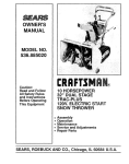
YEPP Model Name:YP-S3 Model Code :YP-S3JCB/EDC SERVICE YEPP Manual CONTENTS 1. Precaution 2. Product Specification 3. Disassembly & Reassembly 4. Troubleshooting 5. Exploded View & Part List 6. PCB Diagram 7. Schematic Diagram YP-S3 Refer to the service manual in the GSPN (see the rear cover) for the more information. GSPN (Global Service Partner Network) Area Web Site North America service.samsungportal.com Latin America latin.samsungportal.com CIS cis.samsungportal.com Europe europe.samsungportal.com China china.samsungportal.com Asia asia.samsungportal.com Mideast & Africa mea.samsungportal.com This Service Manual is a property of Samsung Electronics Co.,Ltd. Any unauthorized use of Manual can be punished under applicable International and/or domestic law. © Samsung Electronics Co.,Ltd. Jul. 2008 Printed in Korea Contents 1. Precaution 1-1 Safety Precautions............................................................................................ 1-1 1-2 Static Electricity Precautions.............................................................................1-2 2. Product Specification 2-1 2-2 2-3 2-4 Product Feature................................................................................................ 2-1 Specifications....................................................................................................2-3 Specifications Analysis......................................................................................2-4 Accessories.......................................................................................................2-6 3. Disassembly & Reassembly 3-1 Overall Disassembly & Reassembly.................................................................3-1 4. Troubleshooting 4-1 Checkpoints by Error Mode..............................................................................4-2 4-2 Upgrade Methods............................................................................................. 4-14 5. Exploded View & Part List 5-1 Exploded View.................................................................................................. 5-2 5-2 Electrical Part List............................................................................................. 5-4 6. PCB Diagram 6-1 PCB Top............................................................................................................6-2 6-2 PCB Bottom......................................................................................................6-4 7. Schematic Diagram 7-1 7-2 7-3 7-4 7-5 7-6 7-7 7-8 7-9 Overall Block Diagram......................................................................................7-2 S5L8700A02.....................................................................................................7-3 MEMORY..........................................................................................................7-4 LCD/KEY...........................................................................................................7-5 USB/MODE/DET............................................................................................... 7-6 AUDIO (EAR JACK).......................................................................................... 7-7 POWER............................................................................................................7-8 FM/RTC.............................................................................................................7-9 CODEC.............................................................................................................7-10 Precaution 1.Precaution 1-1 Safety Precautions 1. To remove dust from cabinet, use a dry cloth without using liquid and aerosol cleaner. 2. You should not use attachments not recommended by the company. Otherwise, it may cause critical damage. 3. You should not use this product near water such as bathtub, swimming pool or lake etc. 4. Power supply: A type of battery as displayed on the label should be only used. 5. You should not put any object or liquid into product. Otherwise, it may cause failure or mal-operation. 6. If replacement material is required, service engineer should use materials with the same standard. The use of non-standardized materials may cause failure of product. Samsung Electronics 1-1 Precaution 1-2 Static Electricity Precautions Some semi-conductor parts may be easily damaged due to static electricity. These elements are generally called as static electricity sense device (ESD). Typically examples of EST include IC, some transistor and chip element for semi-conductor with electrical field effect. The following methods should be used to reduce damage of elements occurred due to static electricity: 1. Contact and emit all the grounding objects with static electricity from your body before handling with elements for semi-conductor or devices with elements for semi-conductor. You should purchase and use static electricity arm rings or commercially available. You should remove it due to potential shock before supplying power to the device under test. 2. You should place appliance on the conductive surface like aluminum film to prevent that static electricity is accumulated or the device is disclosed outside after removing electrical appliance with the ESD device. 3. You should use only soldering iron that is ground when soldering the ESD device. 4. Minimize physical operation when handling with the ESD device for replacement without packing (Otherwise, namely friction between cloth fibers or lifting of the foot from the carpet floor may cause static electricity enough to damage the ESD device). 1-2 Samsung Electronics Product Specification 2.Product Specification 2-1 Product Feature Sparkling - Design: Sparkling Design & Color - GUI & PUI:Sensitive Color/Stella GUI Sensitive image with middle LED button dimming effect Grip & Touch - Grip → Wireless curved 9.8mm Grip → Soft Grip (No edge lines on part that touches hand) → More compact face size than K3 (42.5 x 94 mm) - Touch Pad → Stylish usability with soft control → Complete stylish look with LED lighting Samsung Electronics 2-1 Product Specification Best Audio - DNSe 2.0+ → Enjoy natural sound with new DNSe 2.0+ audio technology → User EQ that can directly set and share precise audio effects - EP380 → EP380 is color-matched to the set and provides perfect audio quality and style (Judged by American audio quality specialist as superior to EP370) - Various Life Styles → Compatible with various accessories such as Cradle Speaker (Samsung Brand & 3rd Vendor), FM Transmitter (3rd Vendor), etc. 2-2 Samsung Electronics Product Specification 2-2 Specifications Basic Specification Rating DC 5.0V/ 500mA Built-in Battery Power 580 mAh/ DC 3.7V File Compatibility AUDIO:MPEG1/2/2.5 Layer3 (8kbps~320kbps, 8kHz~48kHz), WMA(48kbps~192kbps, 8kHz~48kHz), Ogg(Q1~Q10) VIDEO: SVI (Video: MPEG4, Audio: MP3 (44.1kHz, 128kbps), Resolution: 208X176, Frame Rate: 15fps) IMAGE:JPG (Progressive, Sequential Scanning, File Size: less than 3MB) Supported Number of Files Max. 5000 (Include folder) Earphone Output 20mW/Ch. (based on 16Ω) Output Frequency Range 40Hz~20kHz Signal to Noise Ratio 90 dB with 20 kHz LPF (based on 1kHz 0 dB) Play Time Maximum of 25 hours for music playback, Maximum of 4 hours for video playback (Based on: MP3 128kbps, Volume: 15, Normal Mode) Temperature Range for Operation -5~35°C (23~95°F) Case Metal Plating, Plastic Weight 1.87 oz Dimensions (W x H x D) 1.73 x 3.74 x 0.38 inch FM Radio FM Frequency 87.5~108.0MHz FM Signal to Noise Ratio 55 dB FM T.H.D 1% FM Useable Sensitivity 38dBu Samsung Electronics 2-3 Product Specification 2-3 Specifications Analysis Model Name YP-S3 YP-S5 Flash memory (MLC) Flash memory (MLC) Size: 1.8" 262K QCIF TFT LCD Size: 1.8" 262K QCIF TFT LCD Display Color: 262K LCD Display Color: 262K LCD Photo Storage TYPE Display Basic (Real color 65K color) (Real color 65K color) Resolution: 176(H) X 220(V) Resolution: 176(H) X 220(V) Platform Blues (SYS LSI) Blues (SYS LSI) Battery Li-Polymer Li-Polymer 580mAh 600mAh 25 hrs 25 hrs X 5 hrs Color White / Black / Green / Blue / Red White / Black 512M X X 1G X X 2G 4G 8G MP3 WMA OGG (up to Q10) (up to Q10) WAV X X AAC X X Audible X X JPEG FLAC APE WMV X X (176 x 208, 15 Frame) (176 x 208, 15 Frame) (V4.0) - Game/UI Only (V4.0) - Game/UI Only X X Normal, Rock, Classical, Jazz, House, Ballad, Normal, Rock, Classical, Jazz, House, Ballad, R&B, Dance R&B, Dance (9 band control) (9 band control) DNSe Portable: 3D-User, 3D-Studio, DNSe Portable: 3D-User, 3D-Studio, 3D-Stage, 3D-Club 3D-Stage, 3D-Club Street Mode Street Mode (AUI) (AUI) (MP3 file play 0.75~1.3X) (MP3 file play 0.75~1.3X) 20mW/CH 20mW/CH Battery Capacity Playback Time (Earphone) Playback Time (Speaker) Capacity Files MPEG4 (SVI) Swf Others Preset EQ User EQ Special Effect Sound Etc. Sound Feedback Speed Control Alarm OUTPUT POWER : application, X: non-application 2-4 Samsung Electronics Product Specification YP-S3 YP-S5 FM Programmed FM REC. Line in X X Model Name Photo Encoding Tuner Voice Recording Function Video X X FM RDS DMB X X Etc. X X Voice Recording X Recording Format X MP3 Recording Mode X 4 Mode (32Kbps ~128Kbps) Playlist Function (Music) Folder play (Browse) Library File Navigation Photo Viewer Function (Video) Text Viewer Game Wallpaper Clock Etc. Multi language menu Function (Other) Mobile Playlist (Favorite) PC Playlist (SPL, WPL) PC Playlist (SPL, WPL) (Artist, Album, Genre, Title DB sorting) (Artist, Album, Genre, Title DB sorting) (JPEG Slide show, 3X3 Thumbnail) (JPEG Slide show, 3X3 Thumbnail) (book mark/page up, down) (book mark/page up, down) Flash Gaming (3 games) Flash Gaming (3 games) (Wall paper change, Menu color change) (Wall paper change, Menu color change) Clock Screen Saver, Dynamic EQ Display Clock Screen Saver, Dynamic EQ Display 16 LANUAGE 16 LANUAGE - KOR, ENG, FRA, GER, ITA, JPN, - KOR, ENG, FRA, GER, ITA, JPN, CHA-S, CHA-T, RUS, HUG, POR, SPA, DUT, CHA-S, CHA-T, RUS, HUG, POR, SPA, DUT, POL, SWE, Thai POL, SWE, Thai (16languages) + tag (16languages) + tag (Audio/Video/Photo/Text) (Audio/Video/Photo/Text) (Video/Text only) (Video/Text only) Netsync (Korea) SKT Melon (Korea) X X WMA DRM Janus Multi language tag display Resume Bookmark DRM Mobile Playlist (Favorite) : application, X: non-application Samsung Electronics 2-5 Product Specification 2-4 Accessories 2-4-1 Supplied Accessories Accessories 2-6 Item Item code Earphones AH59-01884A USB Cable AH39-00899B Program Installation CD AH46-00057B Remark Samsung Service center Samsung Electronics Disassembly & Reassembly 3.Disassembly & Reassembly 3-1 Overall Disassembly & Reassembly - Be careful to follow the disassembly sequence described in the manual. Otherwise, the product may be damaged. - Be sure to carefully read and understand the safety instructions before performing any work as the IC chips on the PCB are vulnerable to static electricity. - Assemble in the reverse order of disassembly. No Part Name Description 1 CABINETFRONT 1) Insert the S5 or K5 Hinge pin or a corresponding short pin in the service hole. Description Photo 2) Leaving the pen sticking in the bottom, apply pressure from the top and remove both of the FRONT side tapes. When separating them, be careful not to make scratches. 2 FPC-TOUCH 1) Remove the FPC-TOUCH from the TOUCH-PAD’s CONNECTOR. When separating the FPC-TOUCH, use the pin set so as not to break it. Samsung Electronics 3-1 Disassembly & Reassembly No Part Name Description 3 HOLDERLED 1) Use the pen set and pull up from the bottom to the top and remove the HOLDER-LED. 4 LCD 1) Use the pin set and pull up from the bottom to the top and remove the LCD. 5 CABINETMIDDLE Description Photo 1) Remove the CABINET-MIDDLE screw. : CH,+,B,M1.4,L4,NI PLT 2) Remove the CABINET-MIDDLE. 3-2 Samsung Electronics Disassembly & Reassembly No Part Name Description 6 MAIN PCB / BATTERY 1) Insert the pin set in one SIDE of the PCB, then use it as a lever to remove the locking from the hook. Description Photo 2) Remove the battery. 3) How it looks when completely dismantled. Samsung Electronics 3-3 MEMO 3-4 Samsung Electronics Troubleshooting 4.Troubleshooting 4-1 Checkpoints by Error Mode.................................................................4-2 4-2 Upgrade Methods..................................................................................4-14 Samsung Electronics 4-1 Troubleshooting 4-1 Checkpoints by Error Mode Oscilloscope Setting Values Voltage/DIV 1V/div TIME/DIV 10ms/div 4-1-1 If there is no power The power does not turn on. Yes Is there power after charging the Battery? No Has the firmware been upgraded? (See 4-2 Upgrade Methods) Yes No Yes L602: 1.1V, L603: 2.8V Power check No Yes Did XTAL1 CLOCK appear? No Yes Refer to wave pattern image of Fig. 4-1. Check Battery power Check BT1 +, - TP No Malfunction Check power at the Battery? No Replace the Battery and recheck 4-2 Finished Samsung Electronics Troubleshooting 1 1 IC201 S5L8700A02 Page, 7-3 IC200 1 IC103 IC800 PCB Bottom Page, 6-4 <Fig. 4-1> Samsung Electronics JACK500 IC601 4-3 Troubleshooting 4-1-2 If no sound is heard If no sound is heard Are the earphones working? Do the symptoms appear even after replacing the earphones? No Yes Did the sample song play? No Replace earphones Yes Is it play after adding solder to the JACK? No Yes No Yes Check IC600 SHORT Does R/L-CH come out normally? No No Yes Yes No Can audio stoppage or interference be heard? Refer to wave pattern image of Fig. 4-2. Yes No Can it be heard when playing other files? Yes No Do the symptoms appear even after upgrading to the latest firmware? Yes Replace Board (Requires close inspection) Finished 4-4 Samsung Electronics Troubleshooting 1 1 CON302 S/W400 POWER Page, 7-8 IC300 1 IC700 IC701 PCB Top Page, 6-2 <Fig. 4-2> Samsung Electronics 4-5 Troubleshooting 4-1-3 Check that the TOUCH PAD is operating normally Check that the TOUCH PAD is operating normally Is the SWITCH turned to HOLD OFF? No Check that the HOLD SW on the right side of the device is ON. Yes Does the TOUCH KEY respond? No Yes Is the TOUCH PAD malfunctioning? No Disassemble device and check for FPCB malfunction. If TOUCH is malfunctioning, replace TOUCH PAD. Replace Board (Requires close inspection) Yes Disassemble device and check if the TOUCH PAD has come loose 4-6 Samsung Electronics Troubleshooting 4-1-4 When there is no FM reception When there is no FM reception Refer to wave pattern image of Fig. 4-3. Does the XTAL700 32.768 Khz Clock appear? No Yes Is there communication with R700, R701 I2? Is the IC700 RTC operating? No Replace IC Yes No Solder and recheck Yes Finished Samsung Electronics 4-7 Troubleshooting 1 1 CON302 S/W400 FM/RTC Page, 7-9 C300 IC700 1 IC701 PCB Top Page, 6-2 <Fig. 4-3> 4-8 Samsung Electronics Troubleshooting 4-1-5 When the LCD Back Light does not turn on When the LCD Back Light does not turn on Is the USB connected and does the MP3 play? No Yes Finished Samsung Electronics No Finished Yes Yes Does it operate after replacing the LCD? Does it operate after upgrading to the latest firmware? No Is the IC300 Pin 2 enabled? Yes Refer to wave pattern image of Fig. 4-4. Replace Board (Requires close inspection) 4-9 Troubleshooting 1 1 LCD/KEY Page, 7-5 CON302 S/W400 CON301 CON300 IC300 4-10 1 IC700 PCB Top Page, 6-2 <Fig. 4-4> IC701 Samsung Electronics Troubleshooting 4-1-6 When it does not charge When it does not charge Does it operate when the adapter is connected? (Check that the Enable Pin is on High) Yes No Refer to wave pattern image of Fig. 4-5. Disassemble device. Is the battery properly connected? No Does it operate after upgrading the firmware? No Yes Check Connector malfunction Yes Check for power in the Battery? No Replace Battery and check again Yes Finished Samsung Electronics Replace Board (Requires close inspection) 4-11 Troubleshooting 1 3 2 1 2 IC201 IC200 3 POWER Page, 7-8 2 IC103 1 IC800 IC601 PCB Bottom Page, 6-4 <Fig. 4-5> 4-12 CON400 JACK500 3 Samsung Electronics Troubleshooting 4-1-7 Poor PC Connection Connect USB Does the USB connection indicator appear on the LCD? Yes No After RESET does the USB connect? No Yes Yes Is there a mobile storage device in "My Computer"? No In the device manager, is there an unknown device? Yes No Yes No Install driver and recheck Is there ACCESS? Yes No Is formatting occurring in Windows Explorer? Has the DFU NAND FORMAT and BOOT update been done? No Malfunction Yes Finished Samsung Electronics 4-13 Troubleshooting 4-2 Upgrade Methods If the product does not power on and shows any of the following symptoms, you may try the upgrade methods in this chapter without having to disassemble the product: - The product does not turn on when the power switch is pressed. - The product powers on normally but no USB connection can be made. - The product’s icons appear garbled or malfunction. - Files are corrupted, or the product shows as a “removable storage” in Windows but cannot be accessed. 4-2-1 Firmware Upgrade Method 1. When USB is connected check that “USB Mode” is displayed. 2. Latest Firmware [*.ROM] and the Config file [*.DAT] to the portable disk ROOT. 3. Disconnect the USB, press Reset and then turn the power on. 4. As shown in the screen on the side, an Upgrading Firmware message appears and the upgrade commences. 5. Go to “Settings → System → System Information” and check the firmware version. If a Bootloader update is needed, steps 1, 2 and 3 are completed and then step 4 occurs. If the Bootloader update is not needed, only step 4 occurs. 4-14 Samsung Electronics Troubleshooting 4-2-2 Bootloader Upgrade Method When do you perform this procedure?: When NAND data is corrupted How to save the Bootloader in the NAND flash memory 1. With the POWER ON KEY pressed, connect the USB. - Press RESET and connect in DFU Mode. - After DFU connection, the POWER KEY can be released. 2. After connecting the USB, the device must be installed. - After initially installing it once, it connects automatically from thereon. Specify the folder in which DFU is stored. [Bluesdfu_vid419_pid0145.inf Once the device is recognized, it will be connected to USB DFU DEVICE. Samsung Electronics 4-15 Troubleshooting 3. Run the Bluesdfu.exe file in the DFU folder to run the DFU program. 1 Select "UpdateNAND.bin" 2 Select "S3_Erase.bin" 3 Run Download 3 2 1 4 Disconnect and turn the set’s power on. A “Format…” message will appear and the formatting occurs. 5 Push the Reset button and connect it to the PC again. If the Browse button is inactive, there is no DFU connection and you must pull out the USB and try again. 4-16 Samsung Electronics Exploded View & Part List 5.Exploded View & Part List 5-1 Exploded View.......................................................................................5-2 5-2 Electrical Part List.................................................................................5-4 Samsung Electronics This Document can not be used without Samsung’s authorization. 5-1 Exploded View & Part List 5-1 Exploded View AA001 LCD AC010 AK200 AH312 AA225 5-2 AS040 This Document can not be used without Samsung’s authorization. Samsung Electronics Exploded View & Part List Part List Loc. No. Code No. AA001 AH97-02625A AA225 Q’ty SNA ASSY CABINET-BACK;ASSY,YP-S3,BLACK,- 1 SA AH97-02482B ASSY-TOUCH PAD;TOuch PAD ASSY,YP-S3,Syna 1 SA AC010 AH97-02624A ASSY CABINET-FRONT;ASSY,YP-S3,BLACK,- 1 SA AH312 AH61-02541A HOLDER-LED;YP-S3,PC,T1,W20,L20,BLK,- 1 SA AK200 AH64-04524A KNOB-HOLD;YP-S3,PC,T2,W2,L2,-,BLK,-,- 1 SA AS040 6003-001166 SCREW-TAPTITE;CH,+,B,M1.4,L4,NI PLT,SWRC 1 SA BATTERY AH43-00015A ERY;363844,YP-S3,Lithium-Polymer,5 1 SA LCD AH07-00223A .CD-TFT;DA-176TC-02,YP-S3,176X220,34X4 1 SA PCB-MAIN AH92-02796F ASSY PCB-MAIN;YP-S3 MAIN,8GB(RDS) 1 SA Samsung Electronics Description;Specification This Document can not be used without Samsung’s authorization. Remark 5-3 Exploded View & Part List 5-2 Electrical Part List Loc. No. Part No. Description;Specification Q’ty SNA Remark C100 C101 C102 C103 AH92-02796F ASSY PCB-MAIN;YP-S3 MAIN,8GB(RDS) 2404-001381 C-TA,CHIP;10##F,20%,10V,-,TP,1608(0 2203-000254 C-CER,CHIP;10nF,10%,16V,X7R,1005 2203-000330 C-CER,CHIP;0.012nF,5%,50V,C0G,1005 2203-002709 C-CER,CHIP;100nF,+80-20%,16V,Y5V,10 1 1 1 1 1 SA SA SA SA SA C104 C105 C106 C107 C108 2203-002709 2203-002709 2203-002709 2203-006683 2203-002709 C-CER,CHIP;100nF,+80-20%,16V,Y5V,10 C-CER,CHIP;100nF,+80-20%,16V,Y5V,10 C-CER,CHIP;100nF,+80-20%,16V,Y5V,10 C-CER,CHIP;4700nF,+80-20%,6.3V,Y5V, C-CER,CHIP;100nF,+80-20%,16V,Y5V,10 1 1 1 1 1 SA SA SA SA SA C109 C110 C111 C112 C113 2203-002709 2203-002709 2203-002709 2203-002709 2203-000330 C-CER,CHIP;100nF,+80-20%,16V,Y5V,10 C-CER,CHIP;100nF,+80-20%,16V,Y5V,10 C-CER,CHIP;100nF,+80-20%,16V,Y5V,10 C-CER,CHIP;100nF,+80-20%,16V,Y5V,10 C-CER,CHIP;0.012nF,5%,50V,C0G,1005 1 1 1 1 1 SA SA SA SA SA C114 C115 C116 C117 C118 2007-000775 2203-002709 2203-002709 2203-000254 2203-002709 R-CHIP;33Kohm,5%,1/16W,TP,1005 C-CER,CHIP;100nF,+80-20%,16V,Y5V,10 C-CER,CHIP;100nF,+80-20%,16V,Y5V,10 C-CER,CHIP;10nF,10%,16V,X7R,1005 C-CER,CHIP;100nF,+80-20%,16V,Y5V,10 1 1 1 1 1 SA SA SA SA SA C119 C120 C121 C122 C123 2203-000254 2203-000854 2203-000278 2203-002709 2203-006646 C-CER,CHIP;10nF,10%,16V,X7R,1005 C-CER,CHIP;0.039nF,5%,50V,C0G,1005 C-CER,CHIP;0.01nF,0.5pF,50V,C0G,100 C-CER,CHIP;100nF,+80-20%,16V,Y5V,10 C-CER,CHIP;10000nF,10%,6.3V,X5R,201 1 1 1 1 1 SA SA SA SA SNA C124 C129 C130 C131 C132 2404-001381 2203-005993 2203-002487 2203-002487 2203-005993 C-TA,CHIP;10##F,20%,10V,-,TP,1608(0 C-CER,CHIP;68NF,10%,16V,X7R,TP,1005 C-CER,CHIP;4.7nF,10%,25V,X7R,1005 C-CER,CHIP;4.7nF,10%,25V,X7R,1005 C-CER,CHIP;68NF,10%,16V,X7R,TP,1005 1 1 1 1 1 SA SA SA SA SA C133 C134 C138 C139 C200 2203-002709 2404-001381 2203-002709 2203-000254 2203-006646 C-CER,CHIP;100nF,+80-20%,16V,Y5V,10 C-TA,CHIP;10##F,20%,10V,-,TP,1608(0 C-CER,CHIP;100nF,+80-20%,16V,Y5V,10 C-CER,CHIP;10nF,10%,16V,X7R,1005 C-CER,CHIP;10000nF,10%,6.3V,X5R,201 1 1 1 1 1 SA SA SA SA SNA C201 C202 C203 C204 C205 2203-002709 2203-002709 2203-002709 2203-002709 2203-002709 C-CER,CHIP;100nF,+80-20%,16V,Y5V,10 C-CER,CHIP;100nF,+80-20%,16V,Y5V,10 C-CER,CHIP;100nF,+80-20%,16V,Y5V,10 C-CER,CHIP;100nF,+80-20%,16V,Y5V,10 C-CER,CHIP;100nF,+80-20%,16V,Y5V,10 1 1 1 1 1 SA SA SA SA SA C206 C207 C208 C209 C210 2203-002709 2404-001381 2203-002709 2203-006093 2203-006093 C-CER,CHIP;100nF,+80-20%,16V,Y5V,10 C-TA,CHIP;10##F,20%,10V,-,TP,1608(0 C-CER,CHIP;100nF,+80-20%,16V,Y5V,10 C-CER,CHIP;1000nF,+80-20%,6.3V,Y5V, C-CER,CHIP;1000nF,+80-20%,6.3V,Y5V, 1 1 1 1 1 SA SA SA SA SA C211 C301 C302 C303 C304 2203-002709 2203-002709 2203-005900 2203-005900 2203-005900 C-CER,CHIP;100nF,+80-20%,16V,Y5V,10 C-CER,CHIP;100nF,+80-20%,16V,Y5V,10 C-CER,CHIP;1000NF,+80-20%,10V,Y5V,1 C-CER,CHIP;1000NF,+80-20%,10V,Y5V,1 C-CER,CHIP;1000NF,+80-20%,10V,Y5V,1 1 1 1 1 1 SA SA SA SA SA C305 C306 C307 C313 C321 2203-005900 2203-002709 2404-001381 2203-002709 2404-001491 C-CER,CHIP;1000NF,+80-20%,10V,Y5V,1 C-CER,CHIP;100nF,+80-20%,16V,Y5V,10 C-TA,CHIP;10##F,20%,10V,-,TP,1608(0 C-CER,CHIP;100nF,+80-20%,16V,Y5V,10 C-TA,CHIP;100##F,##20%,6.3V,-,REEL, 1 1 1 1 1 SA SA SA SA SA C322 2203-006474 C-CER,CHIP;22000nF,20%,6.3V,X5R,201 1 SA 5-4 Loc. No. Part No. Description;Specification Q’ty SNA Remark C336 C337 C338 C401 2203-002709 2404-001381 2203-002709 2203-006474 C-CER,CHIP;100nF,+80-20%,16V,Y5V,10 C-TA,CHIP;10##F,20%,10V,-,TP,1608(0 C-CER,CHIP;100nF,+80-20%,16V,Y5V,10 C-CER,CHIP;22000nF,20%,6.3V,X5R,201 1 1 1 1 SA SA SA SA C402 C403 C406 C515 C516 2203-006474 2203-005900 2203-006093 2404-001407 2404-001407 C-CER,CHIP;22000nF,20%,6.3V,X5R,201 C-CER,CHIP;1000NF,+80-20%,10V,Y5V,1 C-CER,CHIP;1000nF,+80-20%,6.3V,Y5V, C-TA,CHIP;330uF,20%,2.5V,-,REEL,352 C-TA,CHIP;330uF,20%,2.5V,-,REEL,352 1 1 1 1 1 SA SA SA SA SA C517 C601 C603 C605 C609 2404-001381 2203-006093 2203-006093 2404-001418 2203-000627 C-TA,CHIP;10##F,20%,10V,-,TP,1608(0 C-CER,CHIP;1000nF,+80-20%,6.3V,Y5V, C-CER,CHIP;1000nF,+80-20%,6.3V,Y5V, C-TA,CHIP;10uF,20%,25V,-,TP,3216 C-CER,CHIP;0.022nF,5%,50V,C0G,1005 1 1 1 1 1 SA SA SA SA SA C610 C611 C612 C613 C614 2203-002709 2203-002709 2203-006474 2203-000627 2404-001381 C-CER,CHIP;100nF,+80-20%,16V,Y5V,10 C-CER,CHIP;100nF,+80-20%,16V,Y5V,10 C-CER,CHIP;22000nF,20%,6.3V,X5R,201 C-CER,CHIP;0.022nF,5%,50V,C0G,1005 C-TA,CHIP;10##F,20%,10V,-,TP,1608(0 1 1 1 1 1 SA SA SA SA SA C615 C616 C700 C701 C702 2203-002709 2203-002709 2203-006093 2203-006093 2203-000254 C-CER,CHIP;100nF,+80-20%,16V,Y5V,10 C-CER,CHIP;100nF,+80-20%,16V,Y5V,10 C-CER,CHIP;1000nF,+80-20%,6.3V,Y5V, C-CER,CHIP;1000nF,+80-20%,6.3V,Y5V, C-CER,CHIP;10nF,10%,16V,X7R,1005 1 1 1 1 1 SA SA SA SA SA C703 C704 C705 C706 C707 2203-000254 2203-006093 2203-006474 2203-006474 2404-001491 C-CER,CHIP;10nF,10%,16V,X7R,1005 C-CER,CHIP;1000nF,+80-20%,6.3V,Y5V, C-CER,CHIP;22000nF,20%,6.3V,X5R,201 C-CER,CHIP;22000nF,20%,6.3V,X5R,201 C-TA,CHIP;100##F,##20%,6.3V,-,REEL, 1 1 1 1 1 SA SA SA SA SA C714 C715 C716 C717 C800 2203-000278 2203-000278 2203-000233 2203-005900 2203-005900 C-CER,CHIP;0.01nF,0.5pF,50V,C0G,100 C-CER,CHIP;0.01nF,0.5pF,50V,C0G,100 C-CER,CHIP;0.1nF,5%,50V,C0G,1005 C-CER,CHIP;1000NF,+80-20%,10V,Y5V,1 C-CER,CHIP;1000NF,+80-20%,10V,Y5V,1 1 1 1 1 1 SA SA SA SA SA C801 C802 C804 C805 C806 2404-001381 2203-000627 2203-006093 2404-001381 2203-006093 C-TA,CHIP;10##F,20%,10V,-,TP,1608(0 C-CER,CHIP;0.022nF,5%,50V,C0G,1005 C-CER,CHIP;1000nF,+80-20%,6.3V,Y5V, C-TA,CHIP;10##F,20%,10V,-,TP,1608(0 C-CER,CHIP;1000nF,+80-20%,6.3V,Y5V, 1 1 1 1 1 SA SA SA SA SA C807 C809 C810 C811 CON300 2404-001381 2404-001381 2203-006093 2203-002709 3708-002265 C-TA,CHIP;10##F,20%,10V,-,TP,1608(0 C-TA,CHIP;10##F,20%,10V,-,TP,1608(0 C-CER,CHIP;1000nF,+80-20%,6.3V,Y5V, C-CER,CHIP;100nF,+80-20%,16V,Y5V,10 CONNECTOR-FPC/FFC/PIC;8P,0.5mm,SMD- 1 1 1 1 1 SA SA SA SA SA CON301 CON302 CON400 D100 D101 3710-001436 3711-006119 3710-002410 0601-002094 0601-002094 SOCKET-BOARD TO BOARD;2P,1R,1.27mm, HEADER-BOARD TO BOARD;BOX,34P,2R,0. CONNECTOR-SOCKET;24P,1R,0.5mm,SMD-A LED;SMD(TOP VIEW),WHT,1.6X0.8X0.4M LED;SMD(TOP VIEW),WHT,1.6X0.8X0.4M 1 1 1 1 1 SA SA SA SA SA D102 D103 D104 D105 D106 0601-002037 0601-002037 0601-002037 0601-002037 0601-002037 LED;SMD,BLUE,1.6x0.8x0.4mm,465/470 LED;SMD,BLUE,1.6x0.8x0.4mm,465/470 LED;SMD,BLUE,1.6x0.8x0.4mm,465/470 LED;SMD,BLUE,1.6x0.8x0.4mm,465/470 LED;SMD,BLUE,1.6x0.8x0.4mm,465/470 1 1 1 1 1 SA SA SA SA SA D308 D309 1405-001093 VARISTOR;14V,20A,1x0.5x0.6mm,TP 1405-001093 VARISTOR;14V,20A,1x0.5x0.6mm,TP 1 1 SA SA This Document can not be used without Samsung’s authorization. Samsung Electronics Exploded View & Part List Loc. No. Part No. Description;Specification Q’ty SNA Remark D400 D401 D402 1405-001138 VARISTOR;18Vdc,1A,1x0.5x0.6mm,TP 1405-001138 VARISTOR;18Vdc,1A,1x0.5x0.6mm,TP 0406-001254 DIODE-TVS;UCLAMP0501P,6/-/-V,200W,S 1 1 1 SNA SNA SA D403 D600 D601 D602 D701 0406-001239 0401-000164 0401-000164 0404-001089 0401-000164 1 1 1 1 1 SA SA SA SA SA FINGER1 AH63-01702A GASKET;-,BeCu / SUS,3.1,2.0,3.94,-, FINGER2 AH63-01702A GASKET;-,BeCu / SUS,3.1,2.0,3.94,-, FPC AH97-02537A ASSY-TOUCH PAD FPCB;LAIFU,YP-S3 Tou IC103 0902-001894 IC-MICROPROCESSOR;S5L8700X,24MHz,32 IC200 1105-001659 IC-DRAM;K4M561633,-,256Mbit,4x4Mx16 1 1 1 1 1 SA SA SA SA SA IC201 IC300 IC400 IC501 IC600 IC-FLASH MEMORY;K9HCG08U1M-PCB0,8GB IC-DC/DC CONVERTER;AAT3151,DFN,12P, IC-CMOS LOGIC;7SV08,AND GATE,SC-70, FET-SILICON;FDMA1028NZ,N,20V,3.7A,0 IC-POSI.FIXED REG.;S-1206B15,SOT-23 1 1 1 1 1 SA SA SA SA SA IC601 1203-004684 IC700 0909-001057 IC701 1204-002721 IC800 1002-001529 JACK500 3722-002665 IC-DC/DC CONVERTER;AAT2550,QFN,24P, IC-REAL TIME CLOCK;-,SNT-8A,8P,-,32 IC-TUNER;Si4703-C19-GMR,QFN,20P,3x3 IC-A/D&D/A CONVERTER;WM1800GEFL,24, JACK-EAR PHONE;5P(3Pole),AU,BLK,SMD 1 1 1 1 1 SA SA SA SA SA JFET600 JFET601 L103 L200 L300 0505-001174 0505-001930 3301-001148 3301-001148 3301-001148 FET-SILICON;SI2302ADS,N,20V,2.4A,65 FET-SILICON;MCH3319,P,-12V,-2.6A,MA BEAD-SMD;60ohm,1608,TP,-,- BEAD-SMD;60ohm,1608,TP,-,- BEAD-SMD;60ohm,1608,TP,-,- 1 1 1 1 1 SA SA SA SA SA L400 L402 L403 L404 L501 3301-001148 2703-002203 3301-001364 3301-001364 3301-001364 BEAD-SMD;60ohm,1608,TP,-,- INDUCTOR-SMD;15nH,5%,1005 BEAD-SMD;1000ohm,1608,150mA,TP,1085 BEAD-SMD;1000ohm,1608,150mA,TP,1085 BEAD-SMD;1000ohm,1608,150mA,TP,1085 1 1 1 1 1 SA SA SA SA SA L502 L503 L505 L600 L601 3301-001364 2007-000070 3301-001950 2703-002653 2703-002829 BEAD-SMD;1000ohm,1608,150mA,TP,1085 R-CHIP;0ohm,5%,1/10W,TP,1608 BEAD-SMD;120,1608,TP,-,120/100MHz INDUCTOR-SMD;4.7UH,20%,2828 INDUCTOR-SMD;10uH,20%,2828 1 1 1 1 1 SA SA SA SA SA L602 L603 L700 PCB Q102 3301-001148 BEAD-SMD;60ohm,1608,TP,-,- 3301-001148 BEAD-SMD;60ohm,1608,TP,-,- 2703-000275 INDUCTOR-SMD;33UH,10%,2012 AH41-01102A PCB-MAIN;YP-S3,Lead free, Epoxy,8,N 0504-001193 TR-DIGITAL;KRC408V,NPN,100MW,22K/47 1 1 1 0.25 1 SA SA SA SNA SA Q103 Q104 Q105 Q106 Q600 0505-001930 0505-001930 0504-001193 0504-001193 0504-001193 FET-SILICON;MCH3319,P,-12V,-2.6A,MA FET-SILICON;MCH3319,P,-12V,-2.6A,MA TR-DIGITAL;KRC408V,NPN,100MW,22K/47 TR-DIGITAL;KRC408V,NPN,100MW,22K/47 TR-DIGITAL;KRC408V,NPN,100MW,22K/47 1 1 1 1 1 SA SA SA SA SA Q601 Q602 Q700 R100 R101 0504-001193 0504-001193 0504-001170 2007-000148 2007-007001 TR-DIGITAL;KRC408V,NPN,100MW,22K/47 TR-DIGITAL;KRC408V,NPN,100MW,22K/47 TR-DIGITAL;KRA304V,PNP,100MW,47K/47 R-CHIP;10Kohm,5%,1/16W,TP,1005 R-CHIP;3.9Kohm,5%,1/16W,TP,1005 1 1 1 1 1 SA SA SA SA SA R102 R103 R104 2007-000138 R-CHIP;100ohm,5%,1/16W,TP,1005 2007-000566 R-CHIP;220Kohm,5%,1/16W,TP,1005 2007-000170 R-CHIP;1Mohm,5%,1/16W,TP,1005 1 1 1 SA SA SA 1107-001715 1203-003708 0801-002800 0505-002229 1203-003549 DIODE-TVS;RClamp0502B,6V,125W,SOT-5 DIODE-SWITCHING;KDS121V,80V,100MA,V DIODE-SWITCHING;KDS121V,80V,100MA,V DIODE-SCHOTTKY;RB551V-30,20V,500MA, DIODE-SWITCHING;KDS121V,80V,100MA,V Samsung Electronics Loc. No. Part No. Description;Specification Q’ty SNA Remark R117 R118 2007-007100 R-CHIP;10Mohm,5%,1/16W,TP,1005 2007-000157 R-CHIP;47Kohm,5%,1/16W,TP,1005 1 1 SA SA R119 R120 R121 R125 R126 2007-001325 2007-001325 2007-000148 2007-000982 2007-000982 R-CHIP;3.3Kohm,5%,1/16W,TP,1005 R-CHIP;3.3Kohm,5%,1/16W,TP,1005 R-CHIP;10Kohm,5%,1/16W,TP,1005 R-CHIP;5.6Kohm,5%,1/16W,TP,1005 R-CHIP;5.6Kohm,5%,1/16W,TP,1005 1 1 1 1 1 SA SA SA SA SA R127 R128 R130 R132 R133 2007-007587 2007-000162 2007-000162 2007-000157 2007-000162 R-CHIP;3.6Kohm,1%,1/16W,TP,1005 R-CHIP;100Kohm,5%,1/16W,TP,1005 R-CHIP;100Kohm,5%,1/16W,TP,1005 R-CHIP;47Kohm,5%,1/16W,TP,1005 R-CHIP;100Kohm,5%,1/16W,TP,1005 1 1 1 1 1 SA SA SA SA SA R140 R141 R142 R143 R144 2007-001313 2007-001313 2007-000139 2007-000139 2007-000139 R-CHIP;330ohm,5%,1/16W,TP,1005 R-CHIP;330ohm,5%,1/16W,TP,1005 R-CHIP;220ohm,5%,1/16W,TP,1005 R-CHIP;220ohm,5%,1/16W,TP,1005 R-CHIP;220ohm,5%,1/16W,TP,1005 1 1 1 1 1 SA SA SA SA SA R145 R146 R147 R200 R202 2007-000138 2007-000139 2007-000566 2007-000148 2007-000157 R-CHIP;100ohm,5%,1/16W,TP,1005 R-CHIP;220ohm,5%,1/16W,TP,1005 R-CHIP;220Kohm,5%,1/16W,TP,1005 R-CHIP;10Kohm,5%,1/16W,TP,1005 R-CHIP;47Kohm,5%,1/16W,TP,1005 1 1 1 1 1 SA SA SA SA SA R205 R206 R301 R302 R334 2007-000148 2007-000148 2007-000157 2007-000503 2007-000162 R-CHIP;10Kohm,5%,1/16W,TP,1005 R-CHIP;10Kohm,5%,1/16W,TP,1005 R-CHIP;47Kohm,5%,1/16W,TP,1005 R-CHIP;2.2ohm,5%,1/10W,TP,1608 R-CHIP;100Kohm,5%,1/16W,TP,1005 1 1 1 1 1 SA SA SA SA SA R335 R338 R400 R401 R402 2007-000140 2007-000157 2007-000157 2007-000155 2007-000157 R-CHIP;1Kohm,5%,1/16W,TP,1005 R-CHIP;47Kohm,5%,1/16W,TP,1005 R-CHIP;47Kohm,5%,1/16W,TP,1005 R-CHIP;27Kohm,5%,1/16W,TP,1005 R-CHIP;47Kohm,5%,1/16W,TP,1005 1 1 1 1 1 SA SA SA SA SA R403 R404 R405 R406 R407 2007-000162 2007-000148 2007-000157 2007-000162 2007-007199 R-CHIP;100Kohm,5%,1/16W,TP,1005 R-CHIP;10Kohm,5%,1/16W,TP,1005 R-CHIP;47Kohm,5%,1/16W,TP,1005 R-CHIP;100Kohm,5%,1/16W,TP,1005 R-CHIP;2.7ohm,5%,1/16W,TP,1005 1 1 1 1 1 SA SA SA SA SA R408 R409 R410 R411 R412 2007-007199 2007-000151 2007-000157 2007-000146 2007-000148 R-CHIP;2.7ohm,5%,1/16W,TP,1005 R-CHIP;15Kohm,5%,1/16W,TP,1005 R-CHIP;47Kohm,5%,1/16W,TP,1005 R-CHIP;6.8Kohm,5%,1/16W,TP,1005 R-CHIP;10Kohm,5%,1/16W,TP,1005 1 1 1 1 1 SA SA SA SNA SA R413 R414 R415 R417 R418 2007-000148 2007-000143 2007-000162 2007-000171 2007-000171 R-CHIP;10Kohm,5%,1/16W,TP,1005 R-CHIP;4.7Kohm,5%,1/16W,TP,1005 R-CHIP;100Kohm,5%,1/16W,TP,1005 R-CHIP;0ohm,5%,1/16W,TP,1005 R-CHIP;0ohm,5%,1/16W,TP,1005 1 1 1 1 1 SA SA SA SA SA R419 R420 R421 R422 R423 2007-000171 2007-000157 2007-000171 2007-000078 2007-000171 R-CHIP;0ohm,5%,1/16W,TP,1005 R-CHIP;47Kohm,5%,1/16W,TP,1005 R-CHIP;0ohm,5%,1/16W,TP,1005 R-CHIP;1Kohm,5%,1/10W,TP,1608 R-CHIP;0ohm,5%,1/16W,TP,1005 1 1 1 1 1 SA SA SA SA SA R501 R502 R504 R505 2007-000162 2007-000162 2007-000143 2007-000162 R-CHIP;100Kohm,5%,1/16W,TP,1005 R-CHIP;100Kohm,5%,1/16W,TP,1005 R-CHIP;4.7Kohm,5%,1/16W,TP,1005 R-CHIP;100Kohm,5%,1/16W,TP,1005 1 1 1 1 SA SA SA SA This Document can not be used without Samsung’s authorization. 5-5 Exploded View & Part List Loc. No. Part No. Description;Specification Q’ty SNA Remark R506 2007-000140 R-CHIP;1Kohm,5%,1/16W,TP,1005 1 SA R507 R508 R517 R518 R525 2007-000140 2007-000162 2007-000139 2007-000139 2007-000140 R-CHIP;1Kohm,5%,1/16W,TP,1005 R-CHIP;100Kohm,5%,1/16W,TP,1005 R-CHIP;220ohm,5%,1/16W,TP,1005 R-CHIP;220ohm,5%,1/16W,TP,1005 R-CHIP;1Kohm,5%,1/16W,TP,1005 1 1 1 1 1 SA SA SA SA SA R600 R601 R602 R603 R604 2007-000155 2007-000148 2007-000148 2007-000157 2007-000162 R-CHIP;27Kohm,5%,1/16W,TP,1005 R-CHIP;10Kohm,5%,1/16W,TP,1005 R-CHIP;10Kohm,5%,1/16W,TP,1005 R-CHIP;47Kohm,5%,1/16W,TP,1005 R-CHIP;100Kohm,5%,1/16W,TP,1005 1 1 1 1 1 SA SA SA SA SA R606 R607 R608 R609 R610 2007-007142 2007-008517 2007-007107 2007-000161 2007-000161 R-CHIP;10Kohm,1%,1/16W,TP,1005 R-CHIP;240Kohm,1%,1/16W,TP,1005 R-CHIP;100Kohm,1%,1/16W,TP,1005 R-CHIP;82Kohm,5%,1/16W,TP,1005 R-CHIP;82Kohm,5%,1/16W,TP,1005 1 1 1 1 1 SA SA SA SA SA R611 R612 R613 R614 R615 2007-007138 2007-008304 2007-007589 2007-007132 2007-000157 R-CHIP;27Kohm,1%,1/16W,TP,1005 R-CHIP;300Kohm,1%,1/16W,TP,1005 R-CHIP;68Kohm,1%,1/16W,TP,1005 R-CHIP;15Kohm,1%,1/16W,TP,1005 R-CHIP;47Kohm,5%,1/16W,TP,1005 1 1 1 1 1 SA SA SA SA SA R616 R617 R618 R619 R620 2007-000143 2007-000148 2007-000157 2007-000152 2007-000157 R-CHIP;4.7Kohm,5%,1/16W,TP,1005 R-CHIP;10Kohm,5%,1/16W,TP,1005 R-CHIP;47Kohm,5%,1/16W,TP,1005 R-CHIP;20Kohm,5%,1/16W,TP,1005 R-CHIP;47Kohm,5%,1/16W,TP,1005 1 1 1 1 1 SA SA SA SA SA R700 R701 R702 R703 R704 2007-000140 2007-000140 2007-000143 2007-000140 2007-000140 R-CHIP;1Kohm,5%,1/16W,TP,1005 R-CHIP;1Kohm,5%,1/16W,TP,1005 R-CHIP;4.7Kohm,5%,1/16W,TP,1005 R-CHIP;1Kohm,5%,1/16W,TP,1005 R-CHIP;1Kohm,5%,1/16W,TP,1005 1 1 1 1 1 SA SA SA SA SA R705 R706 R707 R708 R709 2007-000162 2007-000162 2007-001292 2007-000162 2007-001313 R-CHIP;100Kohm,5%,1/16W,TP,1005 R-CHIP;100Kohm,5%,1/16W,TP,1005 R-CHIP;33ohm,5%,1/16W,TP,1005 R-CHIP;100Kohm,5%,1/16W,TP,1005 R-CHIP;330ohm,5%,1/16W,TP,1005 1 1 1 1 1 SA SA SA SA SA R711 R717 R718 R719 R720 2007-000148 2007-000171 2007-000157 2007-000157 2007-000171 R-CHIP;10Kohm,5%,1/16W,TP,1005 R-CHIP;0ohm,5%,1/16W,TP,1005 R-CHIP;47Kohm,5%,1/16W,TP,1005 R-CHIP;47Kohm,5%,1/16W,TP,1005 R-CHIP;0ohm,5%,1/16W,TP,1005 1 1 1 1 1 SA SA SA SA SA R802 R830 S/W100 S/W400 VAR403 2007-000173 2007-000173 3404-001200 3408-001066 1405-001093 R-CHIP;22ohm,5%,1/16W,TP,1005 R-CHIP;22ohm,5%,1/16W,TP,1005 SWITCH-TACT;12V DC,50MA,160GF,3.9X2 SWITCH-SLIDE;4V,0.3A,SP3T,-,- VARISTOR;14V,20A,1x0.5x0.6mm,TP 1 1 1 1 1 SA SA SA SA SA VAR404 VAR407 VAR408 VAR500 VAR501 1405-001093 1405-001093 1405-001093 2203-005493 2203-005493 VARISTOR;14V,20A,1x0.5x0.6mm,TP VARISTOR;14V,20A,1x0.5x0.6mm,TP VARISTOR;14V,20A,1x0.5x0.6mm,TP C-CER,CHIP;220nF,+80-20%,16V,Y5V,10 C-CER,CHIP;220nF,+80-20%,16V,Y5V,10 1 1 1 1 1 SA SA SA SA SA XTAL100 XTAL101 XTAL700 2801-000102 CRYSTAL-SMD;12MHz,30ppm,-,12pF,100o 2801-004339 CRYSTAL-SMD;0.032768MHZ,20PPM,SMD,9 2801-004339 CRYSTAL-SMD;0.032768MHZ,20PPM,SMD,9 AH99-10017V ASSY AUTO INSERT-PCB-MAIN;-,YP-S3,- 1 1 1 1 SA SA SA SNA AH97-02772KASSY-MACHINERY;YP-S3,XAC,-,- AH39-00899B CBF CABLE;ALDSX145,YP-S3,24,1200,3A 1 1 SNA SA 5-6 Loc. No. Part No. Description;Specification Q’ty SNA Remark AH46-00057B S/W APPLICATION-MASTER CD;YP-S3 J,Y AH59-01884A EARPHONE-EP-380;EP-380(BLACK),EP-38 AH63-01219L COVER-BAG;YP-S3,LDPE,T0.1,W80,L120, 1 1 1 SA SA SA AH68-00650L MARK RECYCLE;YP-P2,ELS,ENG,-,MOJO40 AH68-02033E MANUAL-QG;YP-S3,EDC,14 language,-,M AH69-01988A PACKING CASE-TOP;YP-U3,PC,CLEAR,T1. AH97-02646A ASSY PACKING-MIDDLE;ASS’Y,YP-S3,-,- AH69-02224A PACKING-CASE MIDDLE;YP-S3,PC,PACKIN 1 1 1 1 1 SA SA SNA SA SA AH69-02225A PACKING-SHEET MIDDLE;YP-S3,PPR-OTH, AH97-02746A ASSY PACKING-CASE BOTTOM;ASS’Y,YP-S AH69-02201A PACKING-CASE-BOTTOM;YP-T10,PC,-,2,8 AH69-02226A PACKING-SHEET BOTTOM;YP-S3,PPR-OTH, 1 1 1 1 SNA SA SNA SNA AH07-00223A .CD-TFT;DA-176TC-02,YP-S3,176X220,3 AH43-00015A ERY;363844,YP-S3,Lithium-Polymer,5 AH63-01455A SHEET-CASE;YP-U3,PET,T0.1,W20,L8,-, AH68-00508ULABEL SERIAL;COMMON,ELS,-,-,90,-,-, AH68-00701HLABEL SERIAL;YP-T7,ALL,-,-,W20,L5.6 1 1 2 0.1 1 SA SA SNA SNA SNA AH68-50119B LABEL-EAN(B);ART-PAPER,T0.05,L29,W4 AH69-02211GMASTER CARTON;YP-S3,OTHER,T0.7,W251 AH69-02211H MASTER CARTON-PAD;YP-S3,OTHER,T0.7, 1.05 SNA 0.1 SA 0.1 SA This Document can not be used without Samsung’s authorization. Samsung Electronics Exploded View & Part List Model Area EDC XEF XEU XME XSH BAS XAA XAC XSA XSE YP-S3 XBG SUN TSE XSV SMT XSP XTL SKD XSV KOR Code UMS 2GB 4GB 8GB Existing A/S Code Existing A/S Code Existing A/S Code Existing A/S Code AH92-02796B AH82-00164A AH82-00164B AH82-00164C A/S Code AH82-00164A AH82-00164B AH82-00164C Existing AH92-02796A AH92-02796B A/S Code UMS? MTP? Existing Existing A/S Code Existing A/S Code Existing A/S Code Existing AH92-02796A AH92-02796B A/S Code AH82-00164A AH82-00164B Existing A/S Code AH92-02796B AH82-00164A Existing A/S Code AH82-00164B AH82-00164C AH92-02796B AH82-00164A Existing A/S Code AH82-00164C AH82-00164B AH82-00164C AH92-02796B AH82-00164A Existing AH82-00164B AH82-00164C AH92-02796B A/S Code AH82-00164A AH82-00164B AH82-00164C Existing AH92-02796A A/S Code AH82-00164A AH82-00164B AH82-00164C AH82-00164A AH82-00164B AH82-00164C AH82-00164A AH82-00164B AH82-00164C AH82-00164A AH82-00164B AH82-00164C Existing A/S Code Existing A/S Code Existing A/S Code Existing A/S Code AH92-02796B AH82-00164A Existing A/S Code AH82-00164B AH82-00164C AH92-02796B AH82-00164A AH82-00164B AH82-00164C <YP-S3 AS Code Table 1> Samsung Electronics This Document can not be used without Samsung’s authorization. 5-7 Exploded View & Part List Model Area EDC XEF XEU XME XSH BAS XAA XAC XSA XSE YP-S3 XBG SUN TSE XSV SMT XSP XTL SKD XSV KOR Code MTP 2GB 4GB Existing AH92-02796D AH92-02796E A/S Code AH82-00164D AH82-00164E AH82-00164E Existing AH92-02796D AH92-02796E AH92-02796F A/S Code AH82-00164D AH82-00164E AH82-00164E Existing A/S Code 8GB AH92-02796E AH82-00164D AH82-00164E AH82-00164E Existing AH92-02796A AH92-02796B AH92-02796C A/S Code AH82-00164D AH82-00164E AH82-00164E AH92-02796B AH92-02796C AH82-00164E Existing A/S Code Existing A/S Code Existing A/S Code Existing A/S Code AH82-00164D AH82-00164E Existing AH92-02796A AH92-02796B A/S Code AH82-00164D AH82-00164E AH82-00164E Existing A/S Code Existing A/S Code Existing A/S Code Existing A/S Code Existing A/S Code Existing A/S Code Existing A/S Code Existing A/S Code Existing A/S Code Existing A/S Code Existing A/S Code <YP-S3 AS Code Table 2> 5-8 This Document can not be used without Samsung’s authorization. Samsung Electronics PCB Diagram 6.PCB Diagram 6-1 PCB Top............................................................................................................. 6-2 6-2 PCB Bottom....................................................................................................... 6-4 Samsung Electronics 6-1 PCB Diagram 6-1 PCB Top 4 CON302 CON301 S/W400 1 3 TP4 IC300 2 6-2 CON300 TP2 IC700 TP3 IC701 1 Battery Connector - Be careful of polarity when inserting 2 Touch PAD Connector - Insert it to the side - Use the FPCB to connect the PCB with the Touch PAD 3 Power/Hold Switch - Recognized as Power On/Off when pressed for a regular period of time towards the lower direction and self resetting - Recognized as Hold when held in upper direction 4 LCD Connector & Guide Hole - Assembled Top → Down and fixed to top of LCD Samsung Electronics PCB Diagram 6-1-1 Pin Connection 1 CON301 Battery Connector 6-1-2 Test Point Wave Form 4 CON302 LCD Connector TP2 Pin No. Signal Pin No. Signal Pin No. Signal 1 GROUND 1 GROUND 18 LCD_WR 2 VCC 2 LCD_OPTION 19 LCD_D[12] 3 VCC 20 LCD_RDB 4 GROUND 21 LCD_D[11] 5 VCC 22 GROUND 6 LED3 23 LCD_D[10] 7 GROUND 24 LCD_D[0] 8 LED2 25 LCD_D[9] 9 GROUND 26 LCD_D[1] 10 LED1 27 LCD_D[8] 11 LCD_RESET 28 LCD_D[2] 12 VOUT(LED PWR) 29 GROUND 13 LCD_D[15] 30 LCD_D[3] 14 LCD_CE 31 LCD_D[7] 15 LCD_D[14] 32 LCD_D[4] 16 LCD_RS 33 LCD_D[6] 17 LCD_D[13] 34 LCD_D[5] 2 CON300 Touch PAD Connector Pin No. Signal 1 GROUND 2 GROUND 3 GROUND 4 T_RESET 5 T_DATA 6 T_CLK 7 VCC 8 VCC Samsung Electronics TP3 TP4 6-3 PCB Diagram 6-2 PCB Bottom 0 1 9 IC201 IC200 8 2 7 TP6 TP5 IC103 IC800 IC601 3 4 TP1 5 6-4 CON400 JACK500 TP7 1 MEMORY IC - Supports data memory and transmission in system 2 MICOM IC - Controls all system functions 3 DCDC Converter IC - System power 4 32.768 KHz Crystal - System CLOCK 5 USB Connector - Data communication with external devices 6 Earphone Jack - Audio Output 7 CODEC IC - Audio Function power 8 Finger GASKET - ESD internal reinforcement 9 Reset Switch - Resets power for set 0 SDRAM IC - Supports data transfer in system 6 Samsung Electronics PCB Diagram 6-2-1 Pin Connection 5 CON400 USB Jack 6-2-2 Test Point Wave Form 6 JACK500 Earphone Jack TP1 Pin No. Signal Pin No. Signal 1 BAT ID [Low current 450mA] 1 GROUND 2 UART DETECT 2 R-CH 3 VCC [IO 2.8V] 3 L-CH 4 ADAPTOR INPUT 5 ADAPTOR INPUT 6 NC 7 CRADLE DETECT 8 NC 9 NC 10 USB D- 11 NC 12 GROUND 13 UART RX 14 UART TX 15 USB D+ 16 USB POWER 17 LINE OUT R 18 LINE OUT L 19 GROUND 20 CRADLE_ANT (FM) 21 BATTERY INPUT 22 BATTERY INPUT 23 EXTERNAL BATTERY DETECT 24 PBA_CE Samsung Electronics TP5 TP6 TP7 6-5 MEMO 6-6 Samsung Electronics Schematic Diagram 7.Schematic Diagram 7-1 Overall Block Diagram...................................................................................... 7-2 7-2 S5L8700A02....................................................................................................... 7-3 7-3 MEMORY............................................................................................................ 7-4 7-4 LCD/KEY............................................................................................................ 7-5 7-5 USB/MODE/DET................................................................................................ 7-6 7-6 AUDIO (EAR JACK)........................................................................................... 7-7 7-7 POWER.............................................................................................................. 7-8 7-8 FM/RTC.............................................................................................................. 7-9 7-9 CODEC............................................................................................................... 7-10 Samsung Electronics This Document can not be used without Samsung’s authorization. 7-1 Schematic Diagram 7-1 Overall Block Diagram In the Main System, the Processor (S5L8700), SDRAM, Flash Memory, Power Block, Audio DAC and others have a basic circuit block and include the FM-Tuner function block. The display connects with the 1.8 inch TFT LCD. VCC_2.8 VCC_2.8 VDD_BATT Nand Flash SDRAM SD256M16E 32MB(16M*16) Charge Pump (AAT3151) TFT LCD (262K color) TS-180T-008A (176*220) USB 5V Touch Key PAD DC/DC Converter Charger IC (AAT2550) CORE_1.2 VCC_2.8 Core_1.2 VCC_2.8 LCD_D [0..15] XD [0-15] XA [1-12] The IC Serial Interface covers the whole system and has a variety of protocols. First use the host processor (S5L8700) UART and implement the CODEC and FM Tuner functions. VCC_BATT Li-Polymer Batt. 600mAh ADC The audio DAC use to I2C, I2S to achieve Mode Setting and data transmission separately. The power is turned on or off by the Power S/W on the right side of the set. Power is possible through the internal battery or the adapter, and 5V input is possible with the adapter. Power through the adapter charges the battery at AAT2550, and system power (2.8V, 1.2) is made. NF_D [0-7] USB USB Jack USB Controller UART Line-In Line-Out Processor (S5L8700) - 32bit ARM940T (200Mhz) - 16bit CalmADM2E (120Mhz) - 256kb SRAM VCC_2.8 I2S I2S Reset CODEC (WM1800G) Earphone VCC_2.8 DFU Power On USB 5V 7-2 32.768KHz /12Mhz RTC S-35392A I2S FM Tuner (Si4702) This Document can not be used without Samsung’s authorization. Samsung Electronics Schematic Diagram 7-2 S5L8700A02 TP1 POWER TP1 Samsung Electronics This Document can not be used without Samsung’s authorization. 7-3 Schematic Diagram 7-3 MEMORY POWER 7-4 This Document can not be used without Samsung’s authorization. Samsung Electronics Schematic Diagram 7-4 LCD/KEY TP4 POWER TP4 Samsung Electronics This Document can not be used without Samsung’s authorization. 7-5 Schematic Diagram 7-5 USB/MODE/DET POWER AUDIO 7-6 This Document can not be used without Samsung’s authorization. Samsung Electronics Schematic Diagram 7-6 AUDIO (EAR JACK) POWER AUDIO Samsung Electronics This Document can not be used without Samsung’s authorization. 7-7 Schematic Diagram 7-7 POWER POWER TP7 TP5 TP6 TP2 TP2 7-8 This Document can not be used without Samsung’s authorization. TP5 TP6 TP7 Samsung Electronics Schematic Diagram 7-8 FM/RTC TP3 POWER TP3 Samsung Electronics This Document can not be used without Samsung’s authorization. 7-9 Schematic Diagram 7-9 CODEC POWER AUDIO 7-10 This Document can not be used without Samsung’s authorization. Samsung Electronics