1
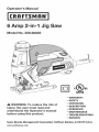
6 Amp 2-in-1 Jig Saw
Model No. 320.28223
• WARRANTY
• SAFETY
WARNING:
To reduce
the risk of
injury, the user must read and
understand the Operator's manual
before using this product.
•
•
•
•
•
•
UNPACKING
DESCRiPTiON
OPERATION
MAINTENANCE
TROUBLESHOOTING
ESPANOL
Sears Brands Management Corporation, Hoffman Estates, IL 60179 U.S.A.
www,cfaftsman,com
Warranty
Page 2
Safety Symbols
Pages 3-4
Safety Instructions
Pages 5-10
Unpacking
Page 11
Description
Pages 12-14
Operation
Pages 14-28
Maintenance
Pages 28-29
Accessories
Page 30
Troubleshooting
Page 31
Exploded
Pages 32-36
View and Parts List
Sears Repair Parts Phone Number
CRAFTSMAN
Back Cover
ONE YEAR FULL WARRANTY
FOR ONE YEAR from the date of purchase, this product is warranted
against any defects in material or workmanship.
Defective product will be
replaced free of charge.
For warranty coverage
details
site: www.craftsman.com
to obtain
free replacement,
visit the web
This warranty does not cover blades and bulbs, which are expendable
that can wear out from normal use within the warranty period.
This warranty is void if this product is ever used while providing
services or if rented to another person.
parts
commercial
This warranty gives you specific legal rights, and you may also have other
rights which vary from state to state.
Sears Brands Management
Corporation,
Hoffman
Estates,
IL 60179
WARNING: Some dust created by using power tools contains chemicals
known to the state of California to cause cancer and birth defects or other
reproductive
harm.
SAVE THESE INSTRUCTIONS!
READ ALL INSTRUCTIONS!
28223
Manual_Revised_S0
0310
Page 2
The purpose of safety symbols is to attract your attention to possible dangers.
The safety symbols and the explanations with them deserve your careful
attention and understanding.
The symbol warnings do not, by themselves,
eliminate any danger. The instructions and warnings they give are no substitutes
for proper accident prevention measures.
,_ WARNING: Be sure to read and understand all safety instructions in this
manual, including all safety alert symbols, such as "DANGER,"
"WARNING,"
and "CAUTION,"
before using this Jig Saw. Failure to following all instructions
listed below may result in electric shock, fire and/or serious personal injury.
SYMBOL
MEANING
SAFETY ALERT SYMBOL:
May be used in conjunction
DANGER:
Indicates DANGER, WARNING,
OR CAUTION.
with other symbols or pictographs.
Failure to obey this safety warning will result in death or serious
injury to yourself or to others. Always follow the safety precautions
risk of fire, electric shock, and personal injury.
WARNING:
Failure to obey this safety warning can result in death or serious
injury to yourself or to others. Always follow the safety precautions
risk of fire, electric shock, and personal injury.
CAUTION:
Failure to obey this safety warning
PREVENTION
AND INFORMATION
to reduce the
may result in death or serious
injury to yourself or to others. Always follow the safety precautions
risk of fire, electric, shock and personal injury.
DAMAGE
to reduce the
to reduce the
MESSAGES
These inform user of important information and/or instructions that could lead to
equipment or other property damage if not followed. Each message is preceded
by the word "NOTE" as in the example below.
NOTE: Equipment
are not followed.
and/or
property
damage
may result
if these
instructions
WARNING: The operation of any power tool can result in
foreign objects being thrown into your eyes, which can result in
severe eye damage. Before beginning power tool operation,
always wear safety goggles or safety glasses with side shields
and a full-face shield when needed. We recommend a Wide
Vision Safety Mask for use over eyeglasses or standard safety
glasses with side shields, available at Sears Stores or other
Craftsman outlets. Always use eye protection that is marked to
comply with ANSI Z87.1
28223
ManuaLRevised_10
0310
Page 3
Some of these following symbols may be used on this tool. Please study them
and learn their meaning. Proper interpretation
of these symbols will allow you to
operate the tool better and safer.
SYMBOL
NAME
DESIG
V
Volts
Voltage
A
Amperes
Current
Hz
Hertz
Frequency
W
Watt
Power
min
Minutes
,m_
Alternating
Direct
no
]
.../min
Current
Current
Alert
Manual
Alert
speed,
Double-insulated
Revolutions,
orbits, etc.,
Eye Protection
Safety
Type of current
Rotational
Per Minute
Read The Operator's
per second)
Type or a characteristic
II Construction
Wet Conditions
(cycles
Time
No Load Speed
Class
NATION/EXPLANATION
of current
at no load
construction
strokes, surface
per minute
locations.
Do not expose
speed,
to rain or use in damp
read and understand
operator's
manual
To reduce the risk of injury, user must
before using this product.
glasses with side shields and a full face
Always wear safety goggles or safety
shield when operating
this product.
Precautions
that involve
your safety.
No Hands
Symbol
blade
Failure will
to keep
result your
in serious
hands personal
away frominjury.
the
No Hands
Symbol
Failure will
to keep
hands personal
away frominjury.
the
blade
result your
in serious
No Hands
No Hands
Symbol
Symbol
Hot Surface
28223 Manual_Revised_$O 0310
blade
Failure will
to keep
result your
in serious
hands personal
away frominjury.
the
blade
result your
in serious
Failure will
to keep
hands personal
away frominjury.
the
To reduce
avoid
contact
the with
risk of
anyinjury
hot surface.
or damage,
Page 4
,_
WARNING:
Be sure to read and understand
all instructions
in this manual
before using the jig saw. Failure to follow all instructions may result in hazardous
radiation exposure, electric shock, fire, and/or serious personal injury.
,_
WARNING:
Do not attempt
to operate this tool until you have thoroughly
read all instructions, safety rules, and warnings. Failure to comply with them can
result in fire, electric shock, or serious personal injury. Save the manual and refer
to it frequently.
SAFETY PRECAUTIONS FOR LASERS
This jig saw has a built-in laser light. The laser is a Class Ilia and emits output
power of a maximum 2.5mW and 650 wavelengths. These lasers do not normally
present an optical hazard. However, do not stare at the beam as this can cause
flash blindness.
The following
label is on your tool. It indicates where
the saw emits the laser light. Be aware of the laser
bystanders
in the vicinity of use are made aware
dangers of looking directly into the laser.
of the
_i_:!_'_io0_:
_,:_';;;;;......
WARNING:
Laser light. Laser radiation.
Avoid Direct Eye Exposure. Do
not stare into beam. Only turn laser beam on when the saw is on the workpiece.
Class Ilia laser.
,_
WARNING:
Use of controls, adjustments
than those specified
or performance
in this manual may result in hazardous
of procedures
other
radiation exposure.
,_k WARNING: The use of optical instruments such as, but not limited to,
telescopes or transits to view the laser beam will increase eye hazard.
CAUTION:
Use of controls
other than those specified
or adjustments
or performance
herein may result in hazardous
of procedures
radiation
exposure
*
Do not remove or deface any product labels. Removing
increases the risk of exposure to laser radiation.
=
The laser beam can be harmful to the eyes. Always avoid direct eye
exposure. Do not look directly into the laser beam output aperture during
operation. Do not project the laser beam directly into the eyes of others. Turn
laser on only when making cuts.
=
Laser enhancing safety glasses are included to enhance the laser beam in
bright light conditions. Do not wear these glasses if they interfere with the
safe operation of this saw.
=
The laser on the jig saw is not a toy. Always keep out of the reach of children.
The laser light emitted from this device should never be directed towards any
person for any reason.
28223
Manual_Revised_SO
03S0
product
labels
Page 5
•
Be sure the laser beam is aimed at a workpiece (such as wood or rough
coated surfaces) that does not have a reflective surface.
Do not use on surfaces such as sheet steel that have a shiny, reflective
surface. The shiny surface could reflect the beam back at the operator. Be
aware that laser light reflected off of a mirror or any other reflective surfaces
can also be dangerous.
Always turn the laser beam off when not in use. Leaving the tool on
increases the risk of someone inadvertently staring into the laser's beam.
CAUTION:
Always follow only the instructions
contained
in this manual
when using this laser. Use of this feature in any manner other than what appears
in this manual may result in a hazardous radiation exposure.
Do not attempt to modify the performance of this laser device in any way.
This may result in a dangerous exposure to laser radiation.
Always use only the accessories that are recommended
by Sears for use
with this product. Use of accessories that have been designed for use with
other laser tools could result in serious injury.
For further information regarding lasers, refer to ANSI-Z136.1 the
STANDARD FOR THE SAFE USE OF LASERS, available from the Laser
institute of America (407) 380-1553.
GENERAL
SAFETY
RULES
WARNING:
Read all safety warnings and instructions. Failure to follow the
warnings and instructions may result in electric shock, fire and / or serious injury.
Save all warnings
and instructions
for future
reference.
The term power tool in the warnings refers to your mains-operated
power tool or battery-operated
(cordless) power tool.
WORK
(corded)
AREA SAFETY
•
Keep work
•
Do not operate power tools in explosive atmospheres,
such as in the
presence of flammable
liquids, gases or dust. Power tools create sparks
which may ignite the dust or fumes.
area clean and well lit. Cluttered
or dark areas invite accidents.
=
Keep children and bystanders
away while operating
Distractions can cause you to lose control.
a power
tool.
ELECTRICAL SAFETY
Power tool plugs must match the outlet. Never modify the plug in any
way. Do not use any adapter plugs with earthed (grounded)
power tools.
Unmodified plugs and matching outlets will reduce risk of electric shock.
Avoid body contact with earthed or grounded
surfaces such as pipes,
radiators,
ranges and refrigerators.
There is an increased risk of electric
shock if your body is earthed or grounded.
28223
ManuaLRevised_10
0310
Page 6
•
Do not expose power tools to rain or wet conditions.
power tool will increase the risk of electric shock.
Water entering
a
=
Do not abuse the cord. Never use the cord for carrying, pulling or
unplugging the power tool Keep cord away from heat, oil, sharp edges or
moving parts. Damaged or entangled cords increase the risk of electric shock.
=
When operating
a power tool outdoors,
use an extension
cord suitable
for outdoor use. Use of a cord suitable for outdoor use reduces the risk of
electric shock.
If operating a power tool in a damp location is unavoidable,
use a
residual current device (RCD) protected
supply. Use of an RCD reduces
the risk of electric shock.
PERSONAL
SAFETY
=
Stay alert, watch what you are doing and use common sense when
operating
a power tool. Do not use tool while tired or under the
influence of drugs, alcohol, or medication.
A moment of inattention while
operating power tools may result in serious personal injury.
=
Use personal protective equipment. Always wear eye protection. Protective
equipment such as dust mask, non-skid safety shoes, hard hat, or hearing
protection used for appropriate conditions will reduce personal injuries.
=
Prevent unintentional
starting.
Ensure the switch is in the off-position
before connecting
to power source and / or battery pack, picking up
or carrying the tool. Carrying power tools with your finger on the switch or
energising in power tools that have the switch on invites accidents.
=
Remove any adjusting
key or wrench before turning the power tool on.
A wrench or a key left attached to a rotating part of the power tool may result
in personal injury.
=
Do not overreach.
Keep proper footing and balance at all times.
enables better control of the power tool in unexpected situations.
=
Dress properly. Do not wear loose clothing or jewellery.
Keep your hair,
clothing and gloves away from moving parts. Loose clothes, jewellery or
long hair can be caught in moving parts.
=
If devices are provided for the connection
of dust extraction
and
collection
facilities,
ensure these are connected
and properly
used. Use
of these devices can reduce dust-related
hazards.
This
POWER TOOL USE AND CARE
•
Do not force the power tool. Use the correct power tool for your
application.
The correct power tool will do the job better and safer at the
rate for which it was designed.
•
Do not use the power tool if the switch does not turn it on and off. Any
power tool that cannot be controlled with the switch is dangerous and must
be repaired.
28223
ManuaLRevised_lO
0310
Page 7
=
Disconnect the plug from the power source and/or the battery pack
from the power tool before marking any adjustments,
changing
accessories,
or storing power tools. Such preventive safety measures
reduce the risk of starting the power tool accidentally.
=
Store idle power tools out of the reach of children and do not allow
persons unfamiliar
with the power tool or these instructions to operate
the power tool. Power tools are dangerous in the hands of untrained users.
=
Maintain power tools. Check for misalignment
or binding of moving
parts, breakage of parts and any other condition
that may affect the
power tool's operation,
if damaged, have the power tool repaired before
use. Many accidents are caused by poorly maintained power tools.
=
Keep cutting
sharp cutting
=
Use the power tool, accessories
and tool bits etc., in accordance
with
these instructions,
taking into account the working conditions
and the
work to be performed. Use of the power tool for operations different from
those intended could result in a hazardous situation.
tools sharp and clean. Properly maintained cutting tools with
edges are less likely to bind and are easier to control.
WARNING: When using power tools, basic safety precautions
be followed to reduce the risk of fire, electric shock, and personal
should always
injury.
_, WARNING: The operation of any tool can result in foreign objects being
propelled into your eyes, resulting in severe eye damage. When operating power
tool, always wear safety goggles or safety glasses with side shields and a full
face shield when needed.
_k
WARNING:
If any parts are missing, do not operate the tool until the missing
parts have been replaced.
SERVICE
Doing so could result in serious
personal
injury.
SAFETY
=
Have your power tool
identical replacement
tool is maintained.
=
If any part of this jig saw is missing or should break, bend, or fail in any
way; or should any electrical component fail to perform properly: shut off the
power switch and remove the saw plug from the power source and have the
missing, damaged, or failed parts replaced before resuming operation.
=
Tool service must be performed only at a Sears Parts & Repair Service
Center. Service or maintenance performed by unqualified personnel could
result in a risk of injury.
=
Use only identical replacement
parts when servicing
instructions in the maintenance section of this manual.
parts or failure to follow
electric shock or injury.
28223
Manual_Revised_SO
0310
serviced by a qualified
repair person using only
parts. This will ensure that the safety of the power
maintenance
instructions
a tool. Follow the
Use of unauthorized
may create a risk of
Page 8
SPECiFiC
,_
SAFETY
DANGER:
RULES FOR JIG SAW
Keep hands away from cutting
hand on the auxiliary handle or motor housing.
saw, the blade cannot cut them.
CAUTION:
area and blade. Keep your second
If both hands are holding the
Blades coast after saw is switched
off.
•
Hold tool by insulated gripping surfaces (handles) when performing an
operation where the cutting tool may contact hidden wiring or its own cord.
Contact with a "live" wire will make the exposed metal parts of the tool "live"
and shock the operator.
•
Use clamps or another practical way to secure and support the
workpiece
to a stable platform. Holding the work by hand or against
body leaves it unstable and may lead to loss of control.
•
Check that the switch
could cause injury.
•
Be aware
is "off" before plugging
the tool in. Accidental
of the function of the switch "Lock-On"
your
starting
button. To switch the lock-
on switch off just by first pressing the switch and then immediately
releasing.
•
Keep your body positioned
with the saw blade.
=
Do not reach underneath the work. The blade guard cannot protect you from
the blade beneath the work.
=
Do not touch the blade or the workpiece immediately
may be extremely hot and could burn your skin.
=
Do not cut an oversized
=
Check for the proper clearance under the workpiece before cutting so that
the blade will not strike the workbench or material under the workpiece.
=
Make sure the blade is not contacting
turned on.
•
Secure material before cutting. Never hold a workpiece in your hand or legs.
Small or thin material may flex or vibrate with the blade, causing loss of control.
•
When ripping, always use a rip fence or straight edge guide (sold separately). This
improves the accuracy of the cut and reduces the chance of the blade binding.
•
Never cut more than one piece at a time. Do not stack more than one
workpiece on the worktable at a time.
•
Avoid awkward
operations
and hand positions
cause your hand to move into the blade.
•
Never reach into the cutting
•
Blade guide rollers must support the blade when cutting. The rollers must
rest against the back edge of blade. The only cutting operation when rollers
do not support the blade is the scrolling mode. When Scrolling the blade
must swivel as it is guided to follow scroll patterns. Always move the base
back and blade guide up and back away from blade in scrolling mode.
28223
Manual_Revised_SO
03S0
to either side of the saw blade, but not in line
after operation;
they
workpiece.
the workpiece
before the switch is
where a sudden slip could
path of the blade.
Page 9
ADDITIONAL
,_
RULES FOR SAFE OPERATION
WARNING:
Be sure to read and understand
all instructions.
Failure to follow
all instructions listed below may result in electric shock, fire and/or
personal injury.
serious
•
Know your power tool. Read operator's manual carefully. Learn the
applications,
as well as the specific potential hazards related to this tool.
Following this rule will reduce the risk of electric shock, fire or serious injury.
•
Always wear safety glasses or eye shields when using this saw. Everyday
eyeglasses have only impact-resistant
lenses; they are not safety glasses.
•
Protect your lungs.
•
Protect your hearing. Wear appropriate personal hearing protection during
use. Under some conditions noise from this product may contribute to
hearing loss.
•
All visitors and bystanders
operator of the saw wears.
•
Inspect the tool cords periodically and if damaged
at your nearest Sears Parts & Repair Service Center.
cord location.
*
Always check the tool for damaged parts. Before further use of the
tool, a guard or other part that is damaged should be carefully checked to
determine if it will operate properly and perform its intended function. Check
for misalignment or binding of moving parts, breakage of parts, and any
other condition that may affect the tool's operation. A guard or other part
that is damaged should be properly repaired or replaced at a Sears Parts &
Repair Service Center.
must wear the same safety equipment
have them repaired
Be aware of the
Inspect
Save these instructions. Refer to them frequently and use them to instruct
others who may use this tool. If someone borrows this tool, make sure they
have these instructions also.
0310
lumber before
that the
*
ManuaLRevised_10
all nails from
is dusty.
*
28223
and remove
Wear a face mask or dust mask if the operation
sawing.
Page 10
A
WARNING: Your saw
when you are assembling
blades, cleaning, or when
accidental starting, which
should never be connected to the power source
parts, making adjustments, installing or removing
it is not in use. Disconnecting
the jig saw will prevent
could cause serious personal injury.
When unpacking the box, do not discard
contents are accounted for:
1. Carefully
any packing
materials
until all of the
lift the jig saw out of the carton and place on a stable, flat surface.
2. Open the color box to locate the following:
* Jig Saw
* 2 blades
* Dust tube
* Hex key
* Carry bag
* Manual
3. Inspect the items carefully
occurred during shipping.
"PARTS LIST" illustration),
which it was purchased to
WARNING:
to make sure that no breakage or damage has
If any of the items mentioned is missing, (refer to
return the jig saw to the Craftsman outlet from
have it replaced.
If any parts are broken or missing, do not attempt to assemble
the jig saw, plug in the power cord, or operate the saw until the broken or missing
parts are replaced. Failure to do so could result in possible serious injury.
CARTON
CONTENTS/LOOSE
PARTS (Fig. 1)
Fig. 1
28223
Manual_Revised_SO
0310
Page 11
KNOW YOUR JIG SAW (Fig. 2)
Fig. 1
On/Off Trigger switch
Scrolling
control
knob
Power Lock-on
button
LaserTrac
button
Top handle
Release button
TM
Power cord
\
Tool-less
"Live tool
indicator"
blade clamp
Push-on
switch
LED
light
Blade storage
Base plate
Bevel Angle scale
Scrolling/Orbit
Locking knob for
edge guide
Edge guide mounting
Laser aperture
ManuaLRevised_10
0310
lever
slot
Variable speed
Vacuum
28223
control
blower knob
Page 12
Before attempting to use this jig saw, familiarize
features and safety requirements.
This Jig Saw has the following
•
yourself with all of its operating
features:
2-in-1 design: use it with the top handle or remove the handle and use it as a
barrel-grip saw.
6 Amp, 800 to 3000 SPM (strokes
per minute) variable speed motor.
LaserTracTM: laser generator
displays
Variable Speed is controlled
trigger switch handle.
by the speed dial located
Scrolling/Orbital
the saw.
Action:
The control
a bright red line along the cutting
lever regulates
1.
SCROLMNG
360 ° blade rotation using scrolling
down blade motion. No orbital action.
2.
Smooth
minimal splintering,
No orbital action.
3.
Low for cutting
4.
Medium
5.
Fast for maximum
the 5 cutting
modes of
knob, normal up and
up and down
blade motion.
most metals, low orbital action.
for cutting
plastics,
hardboard,
medium
orbital action.
orbital action, used for fast cutting in plywood, softwoods.
Blade guide support
15/16-inch
normal
line.
on the back of the
rollers provide added blade control.
blade stroke for faster cutting.
Durable base glides smoothly over the workpiece.
•
Bevel scale for easy adjustment.
Bevel cutting capacity
0 ° to 45 ° left and right.
Quick blade change without tools.
LED worklight
illuminates
"Live tool indicator"
source.
cutting
area.
LED light is green when the saw is plugged into a power
Ergonomically designed 2-in-1 soft-grip handles for maximum control and
balance. Guide the with top mount handle, or use the barrel grip for low
center of gravity precision.
2-way saw dust removal: 1. Blower position blows debris away from cutting
line. 2. Vacuum position for attachment to a wet/dry vac (sold separately).
On board blade storage
Durable cast aluminum
tool from damage.
at base.
and high-impact
Include carry bag for easy carrying
28223
ManuaLRevised_lO
0310
resistant
housing and handle protect
and storage.
Page 13
PRODUCT
SPECIFICATIONS
Input
6 Amps
Laser Diode Type
Red Laser Diode 650 nm
Laser Class
Class Ilia, power output<2.5
No load Speed
800-3000
Rating
120 volts, 60Hz AC
Cutting angle range
0-45 ° left and right
Cutting depth in wood
3-3/8"
Cutting depth in steel
1/4" (6mm)
Weight
6.15 Ibs (2.79 kg)
_,
CAUTION:
The blade guide supports
SPM
(85mm)
the blade when cutting
all times rest against the back edge of the blade, except
mode. It should rotate freely.
TURN POWER ON-OFF
WHEN
1.
Connect the power cord
of your saw to a standard
household power outlet.
2.
Turn your saw on by
sliding the push-on switch
forward until it clicks into
mW
USING THE BARREL
and must at
when in the scrolling
GRIP (Fig. 3)
Fig. 3
the start position.
3.
28223
To turn power off, press in on
the rear section of the pushon switch to stop the tool.
Manual_Revised_S0
0310
Page 14
ATTACHING
TOP HANDLE
ONTO JIG SAW (Fig. 4)
1.
Unplug the saw and put the
push-on switch on the saw
body in the off position.
2.
Hold the handle so that
the curve in the front of the
Fig. 4
handle corresponds with the
curved surface of the saw
body and the lower part of
the rear of the handle aligns
with the attaching plate on
the saw body.
3.
Slide the top handle onto
the attaching plate, and
hold down the handlerelease buttons until the
top handle snaps and locks into place (Fig 4). Release the handle release
buttons.
NOTE: Make sure the push-on
jig saw.
switch
NOTE: When the top handle
is off when attaching
the top handle to the
Fig. 5
is on the jig saw, the push-on
switch cannot be switched on.
TURNING POWER ON/
OFF AND USING LOCK-ON
BUTTON
(Fig. 5}
1.
Connect the power cord
of your saw to a standard
household power outlet.
2.
Start the tool by squeezing
the on/off trigger switch
3.
Release the on/off trigger
switch to stop the tool.
4.
To lock the on/off trigger switch in the "on" position, press trigger switch
and while holding it "on", press in the lock-on button from either side.
The power lock-on button allows the operator to keep the jig saw running
without squeezing the trigger switch. This feature is convenient for
continuous sawing applications.
5.
To release the lock-on
,_k CAUTION:
button,
Do not let familiarity
that a careless fraction of a second
WARNING:
trigger cannot
28223
if the "lock-on"
press and release the trigger
switch.
with your saw make you careless. Remember
is sufficient
button
to cause severe injury.
is continuously
being depressed,
the
be released.
Manual_Revised_SO
0310
Page 15
ADJUSTING
THE CUTTING
SPEED WITH THE VARIABLE
SPEED DiAL (FIG. 6)
The variable speed feature of this jig saw allows you to match the proper cutting
speed to the material being cut, enhancing the overall performance of your saw
and helping to save the blades from undue wear.
1.
The variable speed dial is
r
i
used to adjust the speed of I Fig. 6
the blade.
2.
Turn the dial to increase or
decrease the speed of the
blade (Fig. 6).
3.
I
Position
Variable
Speed Dial
"1" selects the
slowest blade speed;
position "6" selects the
fastest blade speed. Adjust
blade speed for optimum
performance.
NOTE: Determine the optimum
speed for cutting your
workpiece by making a trial cut
in a scrap piece of material.
Workpiece
to be cut
Wood
dial
5- 6
Low-carbon
Stainless
Setting on variable speed
(mild) steel
steel
2- 5
3- 4
Aluminium
3- 6
Plastic
1- 4
WARNING:
Failure to unplug the saw from the power source when
assembling parts, making adjustments or changing
accidental starting causing possible serious injury.
blades could result in
NOTE: Determine the optimum speed for cutting your workpiece by making a
trial cut in a scrap piece of material. Your experience will determine the best
results for a particular application.
However, as a general rule, use slower speed
for harder, denser materials and faster speed for soft materials.
28223
Manual_Revised_S0
0310
Page 16
TOOL=LESS
BLADE iNSTALLATiON
The tool-less blade change
control allows you to remove
and replace the saw blade
quickly and easily without the
use of additional tools.
1.
Unplug the saw.
2.
Turn the saw upside down
so you can access the
blade clamp.
3.
Lift the tool-less
(Fig. 7a, 7b)
Fig. 7a
blade-
change lever up (Fig. 7a),
then insert the blade into
the blade clamp (Fig. 7b).
The teeth of the blade
should be facing to the
front and pointing up (when
saw is right side up, in
cutting position), and the
back of the blade must rest
Tool-less
blade-change
lever
Fig. 7b
in the groove of the blade
guide rollers.
4.
Release the tool-less
blade-change
the blade.
5.
lever to lock
Pull on the blade (see
Fig. 7b) to make sure it is
securely locked in place.
NOTE: For use with both
"T" & "U" shank blades.
CAUTION:
Once the blade is installed
in the saw, it is always exposed.
There is no lower blade guard. Use caution when handling the saw so that the
blade does not catch clothing, skin, etc. Each time you set the saw down, take
care not to bend the blade. Always set saw down on its side when blade is
installed. Always remove blade when saw is not being used.
28223
ManuaLRevised_10
0310
Page 17
_IL CAUTION:
The blade guide
rollers support the blade when
cutting. The blade guide rollers
must rest against the back of
the back edge of the blade. The
ONLY cutting operation where
the blade guide rollers do not
support the blade is when the
saw is in the scrolling mode.
When scrolling, the blade must
swivel as it is guided to follow
the scroll pattern. Always move
the base back and blade guide
rollers up and back away from
the blade when operating in
scrolling mode. (Fig 8a, 8b)
REMOVING
Fig. 8a
,;
Blade
Fig. 8b
THE BLADE
(Fig.7a, 7b)
1.
Blade guide rollers support the
blade when cutting in all cutting
modes except scrolling
..........................
Blade Guide Rollers
Blade guide rollers up and
back away from blade when
operating in the scrolling mode.
Unplug the saw.
WARNING:
Always
unplug saw from the power
source before changing blade
or making any adjustments.
Failure to unplug the saw could
result in accidental starting
which can cause serious
personal
injury.
Blade
2.
Turn the saw upside
for blade removal.
3.
Lift the tool-less
28223
Manual_Revised_SO
down
blade change
0310
Blade Guide Rollers
lever up and carefully
remove
the blade.
Page 18
USING THE LASER TRAC
LIGHT FEATURE (Fig. 9a)
i
TM
i
Fig. 9a
Your jig saw has a built-in laser
light. To activate the laser, plug
in your jig saw.
_, WARNING:
Laser radiation.
Laser light.
Avoid direct
eye exposure. Do not stare into
beam. Only turn laser beam on
when tool is on the workpiece.
Class II laser.
1.
Mark the line of cut on the
workpiece.
2.
Adjust the cutting angle
and cutting speed as needed.
3.
Plug in the saw, and push the laser button to turn on the laser.
4.
Align the laser beam with the line of cut.
5.
Turn on the trigger switch and slowly push the saw forward,
laser beam on the line of cut.
6.
Shut off the laser light when finished cutting.
keeping the
LED WORKLIGHT
Your jig saw has a built-in LED worklight for illuminating the cutting area. To
activate the LED worklight, plug in your jig saw. The LED worklight turns on
automatically
when the tool is plugged in power source.
"LIVE TOOL iNDiCATOR"
LED LIGHT (FIG. 9B)
Your jig saw has a "live tool
indicator" green LED light,
located where the power cord
-Fig. 9b
enters the handle. This light turns
on automatically when the saw is
plugged into a power source.
Live tool indicator
28223
ManuaLRevised_10
0310
LED light
Page 19
SCROLMNG/ORBITAL
CONTROL
LEVER
This jig saw is equipped with an orbital control lever that enables you to select
the type of orbital action best suited for your purpose and workpiece material.
Shift the lever to one of the positions described below prior to starting your cut.
1.
SCROLLINGthis mode allows 360 ° blade rotation using the scrolling knob.
In this mode, there is no orbital action. Use with a scroll blade (available
separately) to cut intricate scroll patterns in all materials with normal up and
down blade motion.
2.
SMOOTH- for cutting all materials with normal up and down blade motion
with minimal splintering. In this mode, there is no orbital action. Use this
mode for cutting hardwoods, mild steel, soft and hard materials with fine
wood cutting and smooth metal cutting blades.
3.
LOW - for cutting most metal, plastics and hardwoods,
aggressive orbital action.
4.
MEDIUM- for cutting most metal, plastics, and hardwoods
aggressive orbital action than the LOW mode.
5.
FAST- for maximum orbital action and the fastest cutting
woods and softer materials.
with a slightly
with a more
in plywood,
Choose the SCROLLING or SMOOTH setting with the scrolling/orbital
lever for normal up and down blade motion (position 1 and 2).
Choose the LOW or MEDIUM settings
actions (position 3 and 4).
for the least aggressive
Choose the FAST setting for the fastest,
orbital blade action (position 5).
most aggressive
orbital
cutting
soft
control
blade
with maximum
NOTE: In order to reach full orbital action, the blade must be facing straight
forward and the back of the blade must rest in the groove of the guide roller.
Position
1
SCROLLING
in all materials.
Position 2
SMOOTH
for reduced in
all materials.
28223
Manual_Revised_S0
0310
Position 3
Position 4
LOW
for metal,
Position 5
FAST
For maximum
orbital action
and faster
MEDIUM
cutting
for plastics,
hardwoods.
plywood and
soft woods.
in
Page 20
CUTTING
WiTH ORBITAL
ACTION
The foot must be all the way in the forward
position:
1.
Unplug the saw.
2.
Turn the tool upside down.
3.
Use the hex key to loosen the hex screw securing
4.
Move the base of the saw forward.
5.
Re-tighten
the saw base.
the hex screws.
Orbital action is not observable when the saw is free-running. The saw must be cutting
for orbital action to occur. The speed of cut is easier to see in thicker materials. See
GENERAL CUTTING TIPS for additional instructions.
SCROLMNG
The scrolling feature allows the
blade to be rotated 360% It is
ideal for cutting curves, designs
and detailed pattern work.
1.
I Fig. 10
I
To engage the scrolling
function, move the
Scrolling/orbit
control
lever to the SCROLLING
position.
(Fig. 10)
2.
Grasp the scrolling
knob (Fig. 11).
control
3.
The scrolling control knob
can be rotated 360 ° to the
left or right while guiding
the saw to follow intricate
cutting
Fig. 11
lines.
NOTE: The blade can be locked
in any scrolling position within
360 ° by switching the Scrolling/
orbit control lever to the
"SMOOTH" position.
NOTE: After moving the lever
into the scrolling position,
turn the scrolling knob back
and forth to be sure the blade
mechanism is locked into the
desired
28223
position.
ManuaLRevised_10
0310
Page 21
IMPORTANT:
When you are manually scroll cutting always hold the saw handle
in one hand and rotate the scrolling knob with your other hand, while applying
pressure to the front of the saw so it does not jump out of the workpiece.
NOTE: When scroll cutting intricate designs, we recommend
cutting blade.
,_
CAUTION:
that you use a scroll
Excessive side pressure to the blade could break the blade which
could damage the material being cut.
2=WAY SAWDUST
REMOVAL
Your jig saw is equipped with a
2-way sawdust removal system.
1.
2.
Unplug the saw.
Switch the
vacuum/blower
(Fig. 12) to
position to
metal and
away from
knob
the BLOWER
blow sawdust,
plastic chips
the cutting area.
OR
1.
2.
3.
4.
Unplug the saw.
Switch the
vacuum/blower
knob
(Fig. 12) to
the VACUUM position.
Fig. 13
Attach the dust tube to the
saw (Fig. 13).
Connect the dust tube
to a 1/4"vacuum adapter
(sold separately) and then
to a standard shop vac to
remove sawdust, metal and
plastic chips.
28223
Manual_Revised_S0
0310
Page 22
ON BOARD BLADE
STORAGE (Fig. 14}
A convenient
feature on the
saw is the blade storage
compartment. The blade storage
compartment is located on either
side of the shoe. To open: pull
the blade storage cover out. To
close: push the cover in with your
thumb or finger.
GENERAL
1.
CUTTING
TiPS
Always place the best
or "finished" side of the
workpiece "face down"
so it does not get scraped or abused while sawing. Always clamp the
workpiece securely before sawing.
2.
Draw your cutting lines, patterns or designs on the "backside" facing you.
This means they would be reversed or backwards from the way they will
appear on the "finished" side.
3.
Always select the correct
4.
Place front edge of saw base on the material to be cut and line up the blade
with your cutting line.
5.
Hold the saw firmly and turn it on.
6.
Press down (to keep base plate flat against the workpiece)
push the saw in the direction of the cut.
7.
Gradually build up the blade speed, cutting as close to the line as possible
(unless you want to leave enough room for finished sanding).
8.
As you cut, you may need to reposition
workpiece stable.
9.
Do not force the saw because the blade teeth may rub and wear without
cutting which may result in breaking the blade.
blade for your cutting application.
as you slowly
the vise or clamps to keep the
10. Let the saw do most of the work.
11. Always cut slowly when following curves, so the blade can cut through
cross grain. This will provide an accurate cut and will prevent the blade
from wandering.
NOTE: Always apply a steady firm "DOWN" pressure on the front and body of the
saw as you cut. This will keep the saw blade from jumping out of the workpiece.
28223
ManuaLRevised_10
0310
Page 23
CUTTING
METAL
When cutting metal, always clamp down the metal workpiece to a stable surface
and use a metal cutting blade. Be extremely careful to move the saw very slowly
as you cut. Use the low speeds (position 1,2 or 3 on the variable speed dial).
Also use the LOW position on the orbital control lever.
Do not twist, bend or force the blade, if the saw jumps or bounces as you cut,
change to a blade with finer teeth, if the blade begins to clog when cutting soft
metal, change to a blade with coarser teeth.
For easier cutting, lubricate the blade with a stick of cutting wax (if available) or
cutting oil when cutting steel. Thin metal should be sandwiched between two
pieces of wood or tightly clamped on a single piece of wood (wood on top of the
metal). Draw the cut lines or design on the top piece of wood.
When cutting aluminum extrusion
and saw close to the vise jaws.
or angel iron, clamp the work in a bench vise
When sawing tubing with a diameter larger than the blade is deep, cut through the
wall of the tubing and then insert the blade into the cut, rotating the tube as you saw.
1.
When cutting
2.
Spread the oil onto the blade or workpiece at regular intervals
in order to reduce wear or overheating the blade.
WARNING:
metals, a suitable cooling/cutting
WARNING:
or attaching
accessories.
Always clamp and secure workpiece
proper control of saw. Failure to clamp and support
control of saw could result in serious injury.
CUTTING
WITH A STRAIGHT
securely. Always
workpiece
maintain
and loss of
EDGE (Fig. 15)
1.
Mark the the desired cut line.
Fig. 15
2.
Clamp a straight edge
parallel to the cut line at a
distance from the cut line
that is equal to the distance
between the blade and the
Straight
edge of the saw base.
edge
3.
during cutting
Always unplug the saw from the power source before oiling the
blade or making any adjustments
,_
oil must be used.
As you cut, keep the saw
base edge flush against the
straightedge and fiat on the
workpiece.
NOTE: Always use a rough-cut
blade whenever possible.
_!_ WARNING: To avoid
accidents, always disconnect the tool from the power source before making any
adjustments or attaching accessories.
28223
Manual_Revised_S0
03S0
Page 24
,_
WARNING:
Do not let familiarity
that a careless fraction of a second
WARNING:
PLUNGE
with your saw make you careless. Remember
is sufficient
to cause severe injury.
Always wear safety goggles or safety glasses when operating this tool.
CUTTING
(Fig. 16)
Plunge cutting is useful and
time-saving for making rough
openings in soft materials, it
makes it unnecessary to drill a
hole for an inside or pocket cut.
1.
Draw lines for the opening
you want to cut.
2.
Hold saw firmly and tilt it
forward so the toe of the
base rests on the workpiece.
3.
Make sure that the blade is
well clear of the workpiece.
4.
Start the saw and then
/
gradually lower the blade
into the workpiece, firmly holding
wobble.
_...._'_-J_
_\.
the toe of the saw base to prevent
side
5.
Slowly pivot the saw downward like a hinge until the blade cuts through
the base rests flat on the workpiece.
6.
Begin sawing
WARNING:
TO MAKE
in the usual manner along the cut line.
Do not use a scroll blade for plunger cutting.
iMPORTANT:
hardwoods
and
Do not try to plunge cut into hard materials,
such as
like oak or maple, or metal such as steel.
SHARP
CORNERS
1.
Cut up to the corner, then
back up slightly before
turning the corner.
2.
After the opening is
complete, go back to each
corner and cut it from
the opposite direction
square it off.
(Fig. 17)
Fig. 17
to
Sharp
Corner
....................................
28223
Manual_Revised_SO
0310
:C;:_
Page 25
TO ADJUST
BASE PLATE FOR BEVEL CUTTING
(Figs.
18 19)
AL_ CAUTION:
Always remove the blade before adjusting
,_k CAUTION:
To prevent damage to the tool when angle or bevel cutting, the
the cutting
angle.
scroll mechanism must be locked in place with the cutting edge of the blade facing
the front of the tool.
1.
To adjust the cutting
angle, first turn the tool
upside down.
2.
Use the hex key to loosen
the hex screw securing the
saw base.
3.
Fig. 18
Move the base of the saw
slightly forward and tilt
it to the required angle
between 0° and 45 °, using
the scale marked on the
base bracket.
4.
Install a cutting
blade.
5.
5. Slide the blade guide
assembly until the blade
guide rests against the
back edge of the blade.
6.
Re-tighten
the hex screws.
For accurate work, it is
necessary to make a trial cut,
measure the work and reset the
angle until the correct
achieved
_,
WARNING:
setting
is
Do not let
familiarity with your saw make
you careless. Remember that a
careless fraction of a second is
sufficient
28223
to cause severe injury.
ManuaLRevised_lO
0310
Page 26
USING AN EDGE GUIDE (sold separately)
An edge guide (sold separately)
is used for straight cutting:
WARNING:
(Fig. 20)
Fig. 20
Always unplug
the saw from the power source
before making any adjustment
or attaching accessories.
1.
Unplug the saw.
2.
Insert the bar of the edge
guide through the slots
in the base of the jig saw
(Fig.19). It can be inserted
from either side of the
base, with the edge guide
facing down.
3.
Screw the edge guide
locking knob into the
threaded hole in the base
Fig. 21
to tighten the edge guide
bar in place.
4.
Measure the distance from
the edge of the workpiece to
the line-of-cut. Slide the edge
guide to this desired distance
and then tighten the locking
knob to secure edge guide in
place. (Fig. 21).
28223
ManuaLRevised_10
0310
Page 27
CIRCLE
CUTTING
(FIG. 22)
Fig. 22
This requires using a circle
cutting / straight edge guide
sold separately.
1.
Before attaching the edge
guide, draw a circle and
drill a hole in the center of
the circle.
2.
Drill or make a plunge cut
near the edge of the circle.
3.
\
Turn off saw and
Center Poi_n¢
disconnect plug from
power source.
4.
Attach the edge guide to
saw as instructed in USING AN EDGE GUIDE, with the edge guide facing up.
5.
Place the metal center point on the edge into the hole in the center of the
circle. In order for the edge guide to cut a circle, the metal center point must
be in alignment with the saw blade.
6.
Measure the distance from the selected
equal to the circle radius.
7.
Insert saw plug into power source.
8.
Hold saw firmly, squeeze the trigger switch and slowly push the saw forward.
hole to the blade; this distance
is
NOTE: To make a hole, cut from inside the circle; to make wheels or discs, cut
from the outside.
GENERAL
MAINTENANCE
WARNING:
When servicing,
use only identical
Craftsman
replacement
parts.
Use of any other parts may create a hazard or cause product damage. To ensure
safety and reliability, all repairs should be performed by a qualified service
technician at a Sears Parts & Repair Service Center.
,_
WARNING:
For your safety, always turn off the switch and unplug the saw
motor from the power source before performing
WARNING:
Always wear safety goggles
during power tool operations
wear a dust mask.
_L, WARNING:
any maintenance
or cleaning.
or safety glasses with side shields
or when blowing dust. If operation
Avoid using solvents when cleaning
is dusty, also
plastic parts. Most plastics
are susceptible to damage from various types of commercial solvents and may
be damaged by their use. Use clean cloths to remove dirt, dust, oil, grease, etc.
28223
Manual_Revised_S0
03S0
Page 28
JIG SAW MAINTENANCE
Periodic maintenance of your jig saw allows for long life and trouble-free
operation. The saw can generate considerable quantities of cutting residue.
A cleaning
and maintenance
schedule
As a common-sense
and preventive
recommended
steps:
•
Inspect
should
be maintained.
maintenance
practice,
follow these
the blade; check the rim for wear or damage.
Keep the ventilation slots of the motor clean to prevent overheating
of the motor.
Electric tools are subject to accelerated wear and possible premature failure
when they are used to work on fiberglass boats and sports cars, wallboard,
spackling compounds or plaster. The chips and grindings from these materials
are highly abrasive to electrical tool parts, such as bearings, brushes,
commutators,
etc. Consequently, it is not recommended that this tool be used
for extended work on any fiberglass material, wallboard, spackling compound,
or plaster. During any use on these materials, it is extremely important that the
tool is cleaned frequently by blowing with an air jet.
Use a soft clean and damp cloth to wipe the tool housing. A mild detergent
can be used but nothing like alcohol, petrol or other cleaning agent. Never
use caustic agents to clean plastic parts.
_l_ WARNING: When changing a blade immediately after operation,
blade to cool before removing it to avoid possible burning.
WARNING:
Keep the tool's air vents unclogged
allow the
and clean at all times.
_, WARNING:
Do not at any time let brake fluids, gasoline, petroleum-based
products, penetrating oils, etc. to come in contact with plastic parts. Chemicals can
damage, weaken or destroy plastic which may result in serious personal injury.
WARNING:
Water must never come into the tool.
LUBRiCATiON
All of the bearings in this tool are lubricated with a sufficient amount of highgrade lubricant for the life of the tool under normal operating conditions.
Therefore, no further lubrication is required.
28223
ManuaLRevised_10
0310
Page 29
The following recommended
accessories
and other selected Craftsman outlets..
,_
WARNING:
The use of attachments
recommended
EXTENSION
might be dangerous
are currently
or accessories
available
at Sears stores
that are not
and could result in serious
injury.
CORDS:
The use of any extension cord will cause some loss of power. To keep the loss
at a minimum and to prevent overheating, use an extension cord that is heavy
enough to carry the current that the tool will draw.
A wire gauge (AWG) of at least 14 is recommended
for an extension cord 25 feet
or less in length. When working outdoors ALWAYS use an extension cord that is
suitable for outdoor use. The cord's jacket will be marked WA.
CAUTION:
Keep extension cords away from the cutting area and position the
cord so it will not get caught on lumber, tools, etc. during the cutting operation.
WARNING:
Check extension cords before each use. If damaged, replace it
immediately. Never use a tool with a damaged extension cord because touching
the damaged area could cause electrical shock resulting in serious injury.
BLADES
Craftsman has a large selection of jig saw blades for fast, efficient
variety of materials and applications
6-in. long, 7 teeth per in
Fast-cutting
3-1/8-in.
long, 10 teeth per in
Fine scrolling
2-3/4-in.
long, 20 teeth per in.
Super-fine
wood scrolling
3-5/8-in.
long, 10 teeth per in.
Super-fine
wood scrolling
3-1/2-in.
long, 8 teeth per in
Wallboard,
plaster
2-3/4-in.
long, 20 teeth per in.
General metal cutting
3-5/8-in.
long, 10 teeth per in.
Bi-metal;
general wood
3-5/8-in.
long, 6 teeth per in.
Bi-metal;
fast-cut
wood
2-3/4-in.
long, 12 teeth per in.
Bi-metal;
general
metal
3-in. long
Manual_Revised_S0
in wood
"Knife-edge"-Iinoleum,
03S0
in a
wood Blade
;raftsman also offers Combination
Squares, Framing Squares
length Edge Guides to help you with all your cutting needs.
28223
cutting
rubber, leather
and various
Page 30
PROBLEM
CAUSE
SOLUTION
Laser line is not
projected,
Laser is not turned on, or
the tool is not plugged in.
Make sure that the tool
is plugged in, and press
Laser ON/OFF button to
turn laser on.
Laser line is hard to
see.
Working
bright,
Reduce surrounding
light level.
LED worklight
illuminate.
does not
LED worklight illuminates
automatically
when tool is
plugged in. Check to see
if tool is plugged in.
Plug tool in. LED
worklight illuminates
automatically
once tool
is plugged into electrical
source.
The Scrolling Control
Knob cannot be turned.
The Scrolling/Orbital
Control Lever is not set to
Set the Scrolling/Orbital
Control Lever to the
the Scrolling
Scrolling
28223
ManuaLRevised_10
0310
condition
is too
position.
position.
Page 31
6A Jig Saw MODEL NUMBER
320.28223
The Model Number will be found on the Nameplate.
Number when ordering parts for this tool.
28223
ManuaLRevised_10
0310
Always mention
the Model
Page 32
6A Jig Saw MODEL NUMBER
320.28223
The Model Number will be found on the Nameplate.
Number when ordering parts for this tool.
1
3320601000
2
1
Left Alum Cover
--
1
L
3
3125316000
Push Button
1
4
3121037000
Cord Guard
1
5
4810002000
Power Cord & Plug
1
6
28223
the Model
Left Housing Assembly
3420338000
L
Always mention
_
5680019000
LHexag°n
Wrench
_
1
7
3320603000
Left Handle Assembly
1
8
3320604000
Right Handle Assembly
1
9
3660030000
Spring
2
10
3123857000
Lock Pin
1
11
3320615000
Lock Button
1
12
3121459000
Switch
Cover
1
13
3420675000
Hander Lever
1
14
3125317000
Switch
1
15
3660072000
Spring
16
3123856000
17
3120457000
Limiting
18
3660054000
Spring
19
3700220000
Connecting
20
3121471000
Pendulum
21
3700536000
Felt Ring
1
22
3700145000
Washer
2
23
5660027000
Circlips
24
3660050000
Spring B
4
25
3700191000
Cap
2
26
5610040000
27
2822669000
ManuaLRevised_10
0310
LockA
1
I Trigger Lock
i Tapping
1
Piece
2
1
Piece
Lever
For Shaft
Screw
Link Assembly
1
1
2
15
1
Page 33
28
29
_
3320104000
Knob Set
1
_ Knob Assembly
_
1
30
3551339000
Bush
31
3420351000
Alum Cover
32
5610022000
33
3120477000
34
3520055000
i Aligning
Bearing
1
35
5610106000
i Tapping
Screw
1
36
3420946000
Drive Bracket
1
37
3520057000
Lower Sliding Bearing
1
38
28223
3320103000
_
1
Screw
2
Bearing Holder
1
i Tapping
3420129000
Sliding
39
5610021000
i Tapping
40
5650001000
Plain Washer
1
41
3120444000
Dust Seal
1
42
3120491000
Guiding
1
43
3550213000
Pendulum
44
3660071000
Spring
1
45
3550202000
Pin
1
46
3550191000
Pin 1
1
47
2822446000
Plunger Assembly
1
48
3550214000
Crank Roller
1
49
5700022000
Needle Bearing
1
50
5660007000
Circlips
1
51
3700183000
Washer C
1
52
3550993000
Gear Set
1
53
5700030000
Needle Bearing
1
54
3700203000
Washer
1
55
3520058000
Pendulum
56
3700224000
Counterweight
57
3700225000
Counterweight
ManuaLRevised_10
0310
Bearing Support
Screw
_
1
3
Block
Pin
1
For Shaft
1
Plate
1
A
2
1
Page 34
58
3700226000
Washer
1
59
3700184000
Washer D
1
60
2820588000
Bearing Support Assembly
1
61
5700045000
Steel Ball
1
62
3120016000
Spring Tube
1
63
5620064000
Screw
2
64
3700227000
Washer
1
65
3550201000
Located
66
2822593000
Roller Support
67
3400175000
Knob
5610079000
Thread
68
28223
_
Pin
1
Set
1
1
Forming Screw
.
12
69
3123859000
Switch Actuator
1
70
3123858000
Lever
1
71
3660051000
Spring
1
72
3123855000
Link
1
73
2750897000
Rotor
1
74
3700164000
Square
75
2740270000
Stator
76
5610024000
Tapping
77
3120234000
Cord Anchorage
1
78
4960017000
Carbon
2
79
2820587000
Brush Support Assembly
1
80
3660055000
Carbon
2
81
4870043000
Switch
1
82
4890524000
PCB Assembly
1
83
4930004000
Connecter
1
84
3123861000
Left Indictor Cover
1
85
4540017000
Power Supply
1
86
3123860000
Right Indictor Cover
1
87
3320248000
Dust tube
1
ManuaLRevised_10
0310
Nut
1
1
Screw
2
Brush
brush Spring
Indicator
Page 35
89
3124066000
Blade Storage
2
90
3421084000
Base Plate
1
91
3124065000
Base Plate Cover
1
93
3700236000
Clamp Washer
1
94
5620013000
Hexagon Socket
Screw
1
95
3320602000
Right Housing Assembly
1
96
2822242000
Blowing Knob
1
97
28223
L
3420339000
L Right Alum Cover
_
1
98
3650099000
Wire Guard
100
3123507000
i Transparent
101
4360001000
LED
1
102
2780030000
Laser Set
1
103
4890523000
PCB Assembly
1
104
5700011000
Ball Bearing
1
105
5700004000
Ball Bearing
1
ManuaLRevised_10
0310
1
Cap
1
Page 36
28223
ManuaLRevised_lO
0310
Page
37
28223
ManuaLRevised_lO
0310
Page
38
28223
ManuaLRevised_lO
0310
Page
39
Your Home
For troubleshooting,
product
manuals
and home solutions
manage
advice:
home
www.managemyhome.com
For repair - in your home - of all major brand appliances,
lawn and garden equipment, or heating and cooling systems,
no matter who made it, no matter who sold it!
For the replacement parts, accessories and
owner's manuals that you need to do-it-yourself.
For Sears professional installation of home appliances
and items like garage door openers and water heaters.
1-800-4-MY-HOME
(1-800-469-4663)
www.sears.corn
®
Call anytime,
day or night
(U.S.A. and Canada)
www.sears.ca
Our Home
For repair of carry-in items like vacuums, lawn equipment,
and electronics, call anytime for the location of the nearest
Sears Parts & Repair Service Center
1-800-488-1222
(U.S.A.)
www.sears.com
1-800-469-4663
(Canada)
www.sears.ca
To purchase a protection agreement on a product serviced by Sears:
1-800-827-6655
(U.S.A.)
Para pedir servicio de reparation
a domicilio, y para ordenar piezas:
1-888-SU-HOGAR®
1-800-361-6665
Au Canada pour service en fran£ais:
1-800-LE-FOYER Mc
(1-800-533-6937)
(1-888-784-6427)
® Registered
Trademark
Tk
/ TMTrademark
(Canada)
www.sea
of KCD IP, LLC in the United States,
® Marea Registrada
/ 4 Marca de F&brica de KCD IP, LLC en Estados
_c Marque de commerce
/ MSMarque dCpos_e de Sears Brands, LLC
Unidos,
rs.ca
or Sears Brands,
o Sears Brands,
LLC in other countries
LLC in otros paises