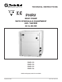
1
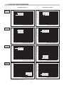
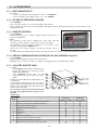
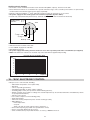
TECHNICAL INSTRUCTIONS
PHRV
HEAT PUMP
WITH HYDRAULIC EQUIPMENT
AIR / WATER
24 to 38 kW
PHRV
PHRV
PHRV
PHRV
22
25
32
36
CHGV cooling only model also available
September 2007
10 12 162 - GB - 02
MARKING
This product marked
conforms to the essential requirements of the Directives:
- Low voltage no. 2006/95/CE.
- Electromagnetic Compatibility no. 89/336 EEC, modified 92/31 EEC and 93/68 EEC.
- Pressure Equipment Directive No. 97/23/CE.
CONTENTS
1
2
3
4
5
6
7
8
9
10
11
12
13
-
Application - Use . . . . . . . . . . . . . . . . . . . . . . . . . . . . . . . . . . . . . . 2
Presentation . . . . . . . . . . . . . . . . . . . . . . . . . . . . . . . . . . . . . . . . . 3
Technical characteristics . . . . . . . . . . . . . . . . . . . . . . . . . . . . . . . . 4
Physical characteristics . . . . . . . . . . . . . . . . . . . . . . . . . . . . . . . . . 5
Description . . . . . . . . . . . . . . . . . . . . . . . . . . . . . . . . . . . . . . . . . . 6
Heating performances . . . . . . . . . . . . . . . . . . . . . . . . . . . . . . . . . .7
Cooling performances . . . . . . . . . . . . . . . . . . . . . . . . . . . . . . . . . .8
Corrections to be made when using anti-freeze . . . . . . . . . . . . . .9
Curves of available pressures . . . . . . . . . . . . . . . . . . . . . . . . . . . .9
Sound levels . . . . . . . . . . . . . . . . . . . . . . . . . . . . . . . . . . . . . . . . .9
Accessories . . . . . . . . . . . . . . . . . . . . . . . . . . . . . . . . . . . . . . . . .10
"ECH" electronic control . . . . . . . . . . . . . . . . . . . . . . . . . . . . . . . .11
Installation information . . . . . . . . . . . . . . . . . . . . . . . . . . . . . . . . .12
APPLIANCES FILLED WITH R 407 C
R 407 C
• Fluid R 407 C, as opposed to R22, is not a pure fluid but a
blend composed of:
- 23% R 32 + 25% R 125 + 52% R 134 A.
• The compressors approved for operation with this fluid are
filled beforehand with polyalcohol oil.
Contrary to mineral oil, it is very hygroscopic: it absorbs the
humidity of the ambient air very quickly. This can modify its
lubricant properties and lead in time to the destruction of the
compressor.
4 - In the case of a new charge:
- do not use the charging cylinder,
- use a balance and a dip pipe type R 407 C cylinder,
- charge the weight of R 407 C as per the value indicated
on the unit’s identification plate,
- IMPORTANT: see instruction 3 above.
5 - The charge must be undertaken in liquid phase.
6 - In case of leakage, do not complete the charge: recover
the remaining refrigerant for recycling and perform a total
charge.
Recovery, recycling or the destruction of the fluid must be
done in compliance with the laws in force in the country
concerned.
7 - If the refrigerant circuit is opened, you must:
- avoid the entry of air into the circuit as much as
possible,
- replace the filter drier,
- perform the "vacuum operation" at a minimum level of
0.3 mbar (static).
8 - Do not release R 407 C fluid into the atmosphere. This
fluid is a fluorinated greenhouse gases, covered by the
Kyoto Protocol with a Global Warming Potential
(GWP) = 1653 - (CE Directive 842 / 2006).
MAINTENANCE INSTRUCTIONS
1 - Never add oil to the appliance; the compressor is filled
with polyalcohol oil, a special oil which cannot tolerate the
presence of other oils.
2 - The instruments used for:
- filling,
- pressure measurements,
- emptying under vacuum,
- recovering the fluid,
must be compatible and only used for the R 407 C fluid.
3 - The weight of the refrigerant contained in the storage
bottle must be checked constantly. Do not use it from the
moment the remaining weight is less than 10% of the total
weight.
1 - APPLICATION - USE
•
•
•
•
•
•
Reversible heat pump with air evaporation for air-conditioning and heating applications.
Single package unit, factory assembled and tested.
Designed for outdoor installation.
Supplied fully charged with R 407 C refrigerant.
Convenient hydraulic and electrical connections.
Practical service access via removable panels.
2
2 - PRESENTATION
PHRV: Reversible heat pump with air evaporation with built-in
hydraulic equipment.
Refrigerant
PHRV
R 407C
Model
1 refrigerant circuit
22 / 25 / 32 / 36
PHRV
9
5
4
b
a
2
7
8
Water inlet
3
6
1
Water outlet
1 SCROLL COMPRESSOR
6 CIRCULATING PUMP
• Mounted on vibration pads with sound insulation.
• Resistance case.
• Circulating pump with heat insulation.
7 EXPANSION TANK
2 WATER EXCHANGER
8 REFRIGERATION CIRCUIT
• Plate water exchanger with heat insulation.
•
•
•
•
•
•
•
3 AIR EXCHANGER
• Thin plate air exchanger with protective grille.
4 ELECTRIC FAN UNIT
• Electric fan unit with protective grille.
5 SWITCH BOX
R407C load.
Copper piping.
Thermostatic regulator.
Filter-dryer.
Fluid cylinder.
HP and LP safety pressure switches.
Cycle inversion valve.
9 CHASSIS - BODYWORK
•
•
•
•
•
“ECH” electronic control
.
Head pressure control.
Main switch
.
Phase-sequence tester.
Power and control circuitry protected by magnetothermal
circuit breakers.
• Complies with standard EN 60 204-1.
• Short circuit current 10 kA, as per IEC 947-2.
• Galvanised sheet metal with light grey oven-baked
polyester powder paint (RAL 7035).
3
3 - TECHNICAL CHARACTERISTICS
PHRV 22
PHRV 25
PHRV 32
PHRV 36
24
9
2.67
11.80
22.7
19.9
4.21
1.17
185
27.30
10.4
2.63
13.60
25.8
20.9
4.68
1.30
145
35.50
13.55
2.62
18.40
34
25
5.94
1.65
140
38.40
14.75
2.60
20
38.7
28.7
7.20
2
95
Available pressure
kW
A
A
m3/ h
L/s
kPa
20.80
8.85
2.35
11.80
22.7
18.6
3.49
0.97
215
25.80
9.7
2.66
13.60
25.8
20
4.5
1.25
160
30.30
13.55
2.24
18.40
34
27.3
5.22
1.45
200
33.50
14.55
2.3
20
38.7
29.3
6.05
1.68
165
Starting current
Electrical supply cable section
A
mm2
145
6
145
6
150
6
190
10
Model
HEATING
Heating capacity
Nominal power consumption*
Performance factor (COP)*
Total Max. power consumption**
Total Max. current consumption**
Rated total input amperage
Nominal water flow
kW
kW
kW
A
A
m3/ h
L/s
kPa
Available pressure
COOLING
Cooling capacity
Nominal power consumption*
(EER)*
Total Max. power consumption**
Total Max. current consumption
Rated total input amperage
Nominal water flow
(*)
(**)
kW
kW
Gross value without hydraulic pump.
In the operating range.
• Power supply:
400V (±10%) / 3 Ph + Neutral + Earth / 50Hz
• Nominal operating conditions:
•
-
COOLING:
water inlet temperature
water outlet temperature
outdoor dry bulb temperature (dry)
•
-
HEATING:
water inlet temperature
water outlet temperature
outdoor dry bulb temperature
outdoor wet bulb temperature
:
:
:
:
: + 12°C
: + 7°C
: + 35°C
+ 40°C
+ 45°C
+ 7°C
+ 6°C
• Operating limits (pure water):
• COOLING:
- temperature of inlet air to condenser
- water outlet temperature
• HEATING:
- outdoor dry bulb temperature
(as per model)
- water outlet temperature
- maximum water inlet temperature
: - 10°C to + 43°C
: + 4°C to + 15°C
: - 10°C to + 20°C
: + 30°C to + 50°C
: + 60°C
• Water system pressure: 1,5 to 3 bar.
Consult us for any special climatic conditions departing significantly from the nominal conditions.
4
4 - PHYSICAL CHARACTERISTICS
Dimensions (in mm) are
given for standard units
without options.
General tolerance ±10 mm.
Condenser air discharge
Electrical connections
Condenser air suction
Location of the 4 anti-vibration pads
(accessory) (100 x 100 x 25 mm) under
girders
a
Chilled water inlet connection
b
Chilled water outlet connection
c
HP and LP hose entry
G
Centre of gravity (in the centre of the unit)
4.1 - PHRV
• Clearances to be respected for unit
operation and maintenance.
• No obstacle less than 3 m above
the unit.
1,175 (1,425 PHRV 36)
HP Manometer
(Accessory)
LP Manometer
(Accessory)
c
a
290
300
300 (600 with tank)
125
b
1,000
40
1,050
4 Ø 22.5 mm holes
for sling attachment
PHRV
Front
22
25
32
36
Net
weight
303 kg
305 kg
327 kg
363 kg
975
Packed
weight
323 kg
325 kg
347 kg
383 kg
Overall
packed
dimensions
Length
Depth
Height
G
1,035 mm
1,135 mm
1,370 mm
1,620 mm
PHRV 36
Access to switch box
G
4.2 - 150-LITRE BUFFER TANK (accessory)
• Clearances to be respected for
maintenance.
300
600
c
a
Hydraulic
connection
tube
Front
b
140 175
611
1,000
(1)
40
Buffer tank
1,050
160
975
Electric heating unit, as
required
Tank
without heating
Tank
with heating
Net
weight
Packed
weight
112 kg
126 kg
128 kg
142 kg
Overall
packed
dimensions
Length
Depth
Height
1,020 mm
1,110 mm
796 mm
5
4 Ø 22.5 mm holes
for sling attachment for
handling the tank only
(1)
: Electric heating power
supply, as required
5 - DESCRIPTION
Model
Cooling circuit (number) with HP and LP pressure switches
R 407 C refrigerant charge
kg
Hermetic SCROLL compressor with soundproofing and internal
thermal protection
Number
Power supply 400V / 3 / 50Hz
Nominal current per compressor
Heating
Cooling
Nominal power consumed by the compressor
Heating
Cooling
A
A
kW
kW
(*)
(**)
•
•
1
1
1
1
•
•
•
•
•
1
9,800
760
620
1
9,800
760
620
1
11,000
760
660
1
11,000
760
660
•
•
•
•
A
3.5
3.5
3.9
3.9
kW
0.75
0.75
0.85
0.85
•
•
•
•
1
1
1
1
•
•
•
•
1
1.7
1
2
1
2.5
1
2.9
liters
liters
liters
kW
A
•
•
•
•
80
250
90
250
120
250
125
250
•8
•
•
•
•
•
•
0.77
•8
•
•
•
•
•
•
0.77
•8
•
•
•
•
•
•
1.06
•8
•
•
•
•
•
•
1.06
1.4
1.4
1.9
1.9
•
•
•
•
•
•
•
•
IP 24
B
IP 24
B
IP 24
B
IP 24
B
If the water volume of the system is below the minimum, a buffer tank must be installed.
If the water volume of the system is above the maximum, an additional expansion tank is required.
6
•
•
Water exchanger with stainless steel brazed plates AISI 316 L with
thermal insulation
Number
Water capacity
liters
Equipment protection index
Electrical equipment
Mechanical risks
•
•
Number
General electrical power supply 400V / 3N + Earth / 50Hz
•
24.2
24.7
14.98
14.48
Air exchanger with protective grille, copper tubes, aluminium fins
Hydraulic circuit
Male 1"1/4 coupling (33x42)
Minimum installation water volume *
Maximum installation water volume **
Expansion tank (1.5 bar)
Tank capacity
Safety valve (3 bar) with pressure gauge
Differential water output pressure switch
Output control valve
Fill valve (ø 1/4" female)
Water filter supplied (not installed)
Circulating pump
Maximum power consumption (pump only)
Maximum current
Power supply 400V / 3 / 50Hz
PHRV 36
1
12.5
20.5
23.4
11.18
12.78
230V / 1 / 50Hz power supply with speed control for condensation
pressure control
Power consumption per motor
PHRV 32
1
9.5
16.7
16.3
8.85
8.95
m3/ h
mm
rpm
Nominal current per motor (single-phase 230 VAC)
PHRV 25
1
9
15.7
14.9
8.51
8.36
Helicoidal electric fan, direct coupling, with internal thermal protector
Number
Air flow
Diameter
Max. rotation speed (motor)
PHRV 22
1
8
6 - HEATING PERFORMANCES
50
35°C
45°C
50°C
46
42
TOTAL INPUT POWER
Total input power (kW)
PHRV 22
Heating capacity (kW)
HEATING CAPACITY
Water outlet temperature
38
34
30
26
-6
-4
-2
35°C
45°C
50°C
46
42
Water outlet temperature
38
34
30
26
11
10
-10 -8
18
-6
-4
-2
35°C
45°C
50°C
17
16
15
0 2 4 6 8 10 12 14
Outdoor wet bulb temperature (°C)
Water outlet temperature
14
13
12
11
10
7
-10 -8
50
-6
-4
-2
35°C
45°C
50°C
46
42
6
0 2 4 6 8 10 12 14
Outdoor wet bulb temperature (°C)
Total input power (kW)
Heating capacity (kW)
12
8
Water outlet temperature
38
34
30
26
18
-4
-2
35°C
45°C
50°C
17
16
15
0 2 4 6 8 10 12 14
Outdoor wet bulb temperature (°C)
Water outlet temperature
14
13
12
11
10
7
-6
-4
-2
35°C
45°C
50°C
46
42
6
0 2 4 6 8 10 12 14
Outdoor wet bulb temperature (°C)
Total input power (kW)
-10 -8
50
Water outlet temperature
38
34
30
26
-10 -8
-6
-4
-2
0 2 4 6 8 10 12 14
Outdoor wet bulb temperature (°C)
18
17
16
15
14
13
12
11
10
9
22
8
18
14
-6
8
18
14
-10 -8
9
22
Heating capacity (kW)
13
9
18
PHRV 36
14
6
0 2 4 6 8 10 12 14
Outdoor wet bulb temperature (°C)
Total input power (kW)
Heating capacity (kW)
-10 -8
22
PHRV 32
15
Water outlet temperature
7
50
14
16
8
18
PHRV 25
35°C
45°C
50°C
17
9
22
14
18
7
-10 -8
-6
-4
-2
0 2 4 6 8 10 12 14
Outdoor wet bulb temperature (°C)
∆ T (water) between 4 and 6°K.
7
6
Water outlet temperature
-10 -8
-6
-4
-2
35°C
45°C
50°C
0 2 4 6 8 10 12 14
Outdoor wet bulb temperature (°C)
7 - COOLING PERFORMANCES
TOTAL INPUT POWER
60
55
50
45
Out.
Out.
Out.
Out.
temp.
temp.
temp.
temp.
7
8
=
=
=
=
Total input power (kW)
PHRV 22
Cooling capacity (kW)
COOLING CAPACITY
15°C
25°C
35°C
45°C
40
35
30
25
20
4
5
6
9 10 11 12 13 14 15
Water outlet temperature (°C)
60
55
50
45
Out.
Out.
Out.
Out.
temp.
temp.
temp.
temp.
7
8
Out.
Out.
Out.
Out.
temp.
temp.
temp.
temp.
=
=
=
=
Total input power (kW)
PHRV 25
Cooling capacity (kW)
15
15°C
25°C
35°C
45°C
40
35
30
25
20
4
5
6
9 10 11 12 13 14 15
Water outlet temperature (°C)
60
55
50
45
=
=
=
=
Total input power (kW)
PHRV 32
Cooling capacity (kW)
15
15°C
25°C
35°C
43°C
40
35
30
25
20
4
5
6
7
8
9 10 11 12 13 14 15
Water outlet temperature (°C)
60
Total input power (kW)
PHRV 36
Cooling capacity (kW)
15
55
50
45
40
35
30
Out.
Out.
Out.
Out.
25
20
15
4
5
6
7
8
temp.
temp.
temp.
temp.
=
=
=
=
15°C
25°C
35°C
45°C
9 10 11 12 13 14 15
Water outlet temperature (°C)
∆ T (water) between 4 and 6°K.
8
19
18
17
16
15
14
13
12
11
10
9
8
7
6
5
19
18
17
16
15
14
13
12
11
10
9
8
7
6
5
19
18
17
16
15
14
13
12
11
10
9
8
7
6
5
19
18
17
16
15
14
13
12
11
10
9
8
7
6
5
4
5
Out.
Out.
Out.
Out.
temp.
temp.
temp.
temp.
7
8
6
Out.
Out.
Out.
Out.
4
5
6
7
Out.
Out.
Out.
Out.
4
5
6
5
6
7
=
=
=
=
8
45°C
35°C
25°C
15°C
9 10 11 12 13 14 15
Water outlet temperature (°C)
=
=
=
=
8
temp.
temp.
temp.
temp.
45°C
35°C
25°C
15°C
9 10 11 12 13 14 15
Water outlet temperature (°C)
8
temp.
temp.
temp.
temp.
7
Out.
Out.
Out.
Out.
4
temp.
temp.
temp.
temp.
=
=
=
=
43°C
35°C
25°C
15°C
9 10 11 12 13 14 15
Water outlet temperature (°C)
=
=
=
=
45°C
35°C
25°C
15°C
9 10 11 12 13 14 15
Water outlet temperature (°C)
8 - CORRECTIONS TO BE MADE WHEN USING ANTI-FREEZE
• IMPORTANT:
Use monopropylene glycol; a minimum rate of 15% to 20% is needed to avoid any risk of corrosion.
PRINCIPLE OF USING THE CURVES
Correction factors
A - Choose the percentage of glycol according to the
minimum temperature to protect the hydraulic circuit
against frost.
B - Example:
Protection at an external temperature of -15°C, which
gives 30% glycol (freezing points curve).
The loss of capacity is given on the "Reduction of
cooling capacity" curve (0.94).
The new flow is given by the coefficient on the water
flow curve (1.113).
Likewise, to determine the new pressure drop
coefficient in relation to the nominal flow, read the
pressure drop curve (1.19).
Valid curves for setting temperature at the water
inlet.
1.30
Pressure drop
1.20
1.19
Water flow
1.113
Outdoor temperature °C
1.10
1.00
Reduction of cooling capacity
0.94
-25
-20
-15
-10
-5
Freezing points
0
10
0
20
30
40
% Glycol in weight
Available head (kPa)
9 - AVAILABLE PRESSURE CURVES ON THE HYDRAULIC SYSTEM
350
PHRV 36
PHRV 32
PHRV 25
PHRV 22
300
250
200
150
100
50
0
2.5
3
3.5
4
4.5
5
5.5
6
6.5
7
7.5
8
8.5
Water flow rate (m3/h)
• Values at apparatus outlet without tank. (See § 11.5 for tank pressure losses).
10 - SOUND LEVELS
PHRV
22
25
32
36
Power level
(dBA)
79
78
80
82
Sound-pressure level
(dBA)
51
50
52
54
• Nominal operating conditions:
- Ambient temperature: 35°C
• Sound-pressure level:
- Unit installed outdoors (free field) on a reflective surface.
- Measurement carried out at a distance of 10 m.
9
dB to be 40
deducted from
the sound
power level
35
30
25
10
15
20
25
30
Distance in meters
11 - ACCESSORIES
11.1 - ANTI-VIBRATION KIT
• Kit includes:
- 1 set of 4 anti-vibration plates, thickness 25 mm - code 70600035.
- 1 set of 2 flexible hoses: length 1 m, Ø 1" 1/4 - code 70600027.
11.2 - HP AND LP PRESSURE GAUGES
• Code 70970007.
• The accessory includes 1 set of 2 pressure gauges (HP and LP).
• These elements, mounted on the vertical members of the unit's front face, display the high and low pressure values for each
refrigeration circuit.
11.3 - REMOTE CONTROL
• Code 70250055.
• Enables reporting of the controller's display keypad functions up to a
distance of 100 meters.
• Note:
The generator's control unit is configured to receive "On / Off" and
"Heating / Cooling" orders by external dry contacts (not included).
By modifying a parameter during installation, it is possible to select
"Heating / Cooling" by the "MODE" button.
In this case, the selection "Heating / Cooling" by external contact is
inactive.
For PHRV units with supplementary heating in the tank, the device can only be controlled by external dry contacts.
11.4 - SERIAL COMMUNICATIONS INTERFACE RS 485 (MODBUS Protocol)
• Code 70250056.
• Interface module installed inside the unit's electrical box.
• MODBUS protocol. Please consult us for details concerning the protocol and addressing of data.
11.5 - 150-LITRE BUFFER TANK
• 2 models:
- code 70600110: model without supplementary
heating with 800 W frost protection resistor
(single-phase 230 VAC),
- code 70200240: model with 24 kW
supplementary heating (in 400 Vac, threephase).
• Designed to be installed either underneath the unit,
or separately.
For installation underneath the unit, the tank is
supplied with mounting brackets and an insulated
tube for connection between the unit's water outlet
and the tank's water inlet.
The electrical connections between the unit and
the tank with supplementary heating are not
supplied.
Composition:
5
1
Water outlet
(Male 1”1/4)
2
Water inlet
(Male 1”1/4)
3
4
6
Mark
1
2
3
4
5
6
7
8
Sheetmetal buffer tank - polyurethane insulation
Branch connections for heating resistances
Set of three 8 kW resistances
800 W anti-freeze resistance
Fill valve
Drain valve
Purge
Safety valve (5 bar)
Water pressure fail pressure switch
Supplementary heating control unit
Galvanized steel chassis, painted RAL 7035
10
7
8
70600110
without heating
70200240
with heating
•
•
•
•
•
•
•
•
•
•
•
•
•
•
•
•
•
•
Auxiliary electric heating:
• The heater consists of immersion heaters each rated at 8 kW (400 V, 3-phase), mounted on the tank.
• These immersion heaters are controlled from a specific unit with 2-stage control, and the power feeders are protected by
circuit breakers and a master switch (power supply separated).
• Backup is authorized with the 2nd stage, although is triggered only if the generator is out of service.
• The power supply for this heating system is connected separately (3-phase 400 V).
• Protection by 2-threshold safety thermostat (1 automatic reset threshold and 1 manual reset threshold).
Heating power : 24 kW
Current
: 35 A
Tank
Immersion heater with security
1st stage - 8 kW
2nd stage - 8 kW
Back-up - 8 kW
Anti-freeze resistance:
•
•
•
•
•
Immersion heater mounted on the tank.
Power: 800 W, single-phase 230 VAC.
With limiting thermostat.
The power supply and heating element control are to be done separately at the time of installation (not supplied).
NOTE: The anti-freeze resistance is mounted only on the tank without supplementary heating.
Pressure losses in 150-litre tank
KPa
8
7
6
5
4
3
2
1
0
3
4
5
6
7
Output m3/h
12 - "ECH" ELECTRONIC CONTROL
• Microprocessor control module, including:
- chilled water temperature control (water inlet),
- defrosting,
- control of operating parameters,
- self-adapting algorithm for water volume reduction,
- circulating pump control (frost protection and anti-sticking function),
- dynamic setpoints are possible according to the outside temperature (to be activated at the time of installation by means
of special parameterization).
- anti-short cycle system,
- hour counter compressor and circulating pump,
- alarm management,
- anti-freeze security (temperature probe at water exchanger outlet),
- digital display of:
. water temperature,
. set-point,
. alarm code (HP, LP, water output, probes, anti-freeze...).
- remote alarm reporting is possible via a potential-free contact,
- remote control with display unit (accessory),
- serial communications port (RS 485 interface, accessory) - MODBUS Protocol.
11
13 - INSTALLATION INFORMATION
• See details in the installation manual.
13.1 - INSTALLATION
• Protection index of the unit:
: for the electrical equipment,
- IP 24
(IPXXB : for the mechanical hazards).
• Before installation, verify the following points:
- the unit must be installed outside in an appropriate location and in compliance with environmental requirements (sound
level, integration, etc...),
- the unit’s installation location must be perfectly level and strong enough to support the weight of the unit and must have
adequate inundation protection,
- sufficient space around the unit should be provided in order to facilitate servicing and maintenance operations,
- air suction to the coil and fan discharge must not be obstructed,
- install the unit above the region’s average snowfall level,
- vibrations and noise must not be transmitted to adjacent buildings,
- install the machine on anti-vibration pads and fit hoses on piping elements, as required,
- if necessary, consult an acoustics specialist concerning the unit’s optimum location,
- 4 holes Ø 22.5 enable to place hoisting hooks and lift the unit.
13.2 - ELECTRICAL CONNECTIONS
• All required information is indicated on the electrical diagram provided with the unit and in the installation manual.
• Connections are to be made in compliance with the standard code of practice and as per the standards in force at the site
of installation.
13.3 - HYDRAULIC CONNECTIONS
• The hydraulic connections are to be made in compliance with the standard code of practice.
• IMPERATIVE: Install the filter supplied on the water inlet of the unit.
13.4 - STARTING - MAINTENANCE
• Refer to the installation guide and the maintenance manual.
• IMPORTANT:
- The unit's electronic control features a frost protection device that automatically starts the water circulating pump
depending on the outside temperature (adjustable threshold), even if the unit is turned off.
- In the event the unit may be taken out of service or in the case of a high risk of freezing:
- either drain the installation,
- or add glycol to the circuit.
- Tank anti-freeze resistance:
its electrical power supply and control must be separate from those of the unit.
Due to our policy of continuous development, our products are liable to
modification without notice.
R.D. 28 Reyrieux BP 131 01601 Trévoux CEDEX France
Phone 33 4 74 00 92 92 - Fax 33 4 74 00 42 00
R.C.S. Bourg-en-Bresse B 759 200 728