1
Dell™ 2130cn Color Laser Printer User's Guide Dell™ 2130cn Color Laser Printer User's Guide
Finding Information
About Your Printer
Installing the Print Head Device (PHD) Unit and Toner Cartridges
Connecting Your Printer
Dell Printer Configuration Web Tool
Installing Optional Modules
Print Media Guidelines
Loading Print Media
Operator Panel
Printer Settings
Understanding the Tool Box Menus
Understanding the Printer Menus
Understanding Your Printer Software
Printing
Setting Up for Shared Printing
Understanding Fonts
Understanding Printer Messages
Clearing Jams
Troubleshooting Guide
Installing Printer Drivers
Printing With Web Services on Devices (WSD)
Maintaining Your Printer
Removing Options
Printer Specifications
Appendix
Notes, Notices, and Cautions
NOTE: A NOTE indicates important information that helps you make better use of your printer.
NOTICE: A NOTICE indicates either potential damage to hardware or loss of data and tells you how to avoid the problem.
CAUTION: A CAUTION indicates a potential for property damage, personal injury, or death.
Information in this document is subject to change without notice.
© 2008 Dell Inc. All rights reserved.
Reproduction in any manner whatsoever without the written permission of Dell Inc. is strictly forbidden.
Trademarks used in this text: Dell, the DELL logo, Inspiron, Dell Precision, Dimension, OptiPlex, Latitude, PowerEdge, PowerVault, PowerApp, and Dell OpenManage
are trademarks of Dell Inc.; Intel, Pentium, and Celeron are registered trademarks of Intel Corporation; Microsoft, Windows, Windows Server, MS-DOS and
Windows Vista are either trademarks or registered trademarks of Microsoft Corporation in the United States and/or other countries. EMC is the registered
trademark of EMC Corporation; ENERGY STAR is a registered trademark of the U.S. Environmental Protection Agency. As an ENERGY STAR Partner, Dell Inc. has
determined that this product meets the ENERGY STAR guidelines for energy efficiency; Adobe and Photoshop are registered trademarks or trademarks of
Adobe Systems Incorporated in the United States and/or other countries.
Other trademarks and trade names may be used in this document to refer to either the entities claiming the marks and names or their products. Dell Inc.
disclaims any proprietary interest in trademarks and trade names other than its own.
Our printer software uses some of the codes defined by the Independent JPEG Group.
UNITED STATES GOVERNMENT RESTRICTED RIGHTS
This software and documentation are provided with RESTRICTED RIGHTS. Use, duplication or disclosure by the Government is subject to restrictions as set
forth in subparagraph (c)(1)(ii) of the Rights in Technical Data and Computer Software clause at DFARS 252.227-7013 and in applicable FAR provisions: Dell
Inc., One Dell Way, Round Rock, Texas, 78682, USA.
November 2008 Rev. A01
Downloaded from ManualsPrinter.com Manuals
Back to Contents Page
Print Media Guidelines
Paper
Envelopes
Labels
Storing Print Media
Identifying Print Media Sources and Specifications
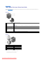
Print media is paper, labels, envelopes, and coated paper among others. Your printer provides high-quality printing on a variety of print media. Selecting the
appropriate print media for your printer helps avoid printing troubles. This section describes selecting print media, caring for print media, and loading the print
media in the standard 250-sheet tray or optional 250-sheet feeder.
Paper
For the best print quality in color, use 75 g/m2 (20 lb) xerographic, grain long paper. For the best print quality in black and white, use 90 g/m2 (24 lb)
xerographic, grain long paper. Before buying large quantities of any print media, it is recommended that you try a sample first.
When loading paper, identify the recommended print side on the paper package, and load the paper accordingly. See "Loading Print Media in the Standard
250-Sheet Tray and Optional 250-Sheet Feeder" and "Loading the Single Sheet Feeder" for detailed loading instructions.
Paper Characteristics
The following paper characteristics affect print quality and reliability. It is recommended that you follow these guidelines when evaluating new paper stock.
Weight
The standard 250-sheet tray automatically feeds paper weights from 60 to 216 g/m2 (16 to 80 lb bond) grain long. The single sheet feeder automatically feeds
paper weights from 60 to 216 g/m2 (16 to 80 lb bond) grain long. Paper lighter than 60 g/m2 (16 lb) may not feed properly, and could cause paper jams. For
best performance, use 75 g/m2 (20 lb bond) grain long paper.
NOTE: The optional 250-sheet feeder automatically feeds paper weights from 60 to 105 g/m2 (16 to 80 lb bond) grain long. Paper lighter than 60 g/m2
(16 lb) may not feed properly, and could cause paper jams. For best performance, use 75 g/m2 (20 lb bond) grain long paper.
Curl
Curl is the tendency of print media to curve at its edges. Excessive curl can cause paper feeding problems. Curl usually occurs after the paper passes through
the printer, where it is exposed to high temperatures. Storing paper unwrapped, even in the paper tray, can contribute to paper curling prior to printing and
cause feeding problems regardless of humidity. When printing on curled paper, straighten the paper and then insert it into the single sheet feeder.
Smoothness
The degree of paper smoothness directly affects print quality. If the paper is too rough, the toner does not fuse to the paper properly, resulting in poor print
quality. If the paper is too smooth, it can cause paper feeding problems. Smoothness between 150 and 250 Sheffield points produces the best print quality.
Moisture Content
The amount of moisture in the paper affects both print quality and the ability of the printer to feed the paper properly. Leave the paper in its original
packaging until you are ready to use it. This limits the exposure of the paper to moisture changes that can degrade its performance.
Grain Direction
Grain refers to the alignment of the paper fibers in a sheet of paper. Grain is either grain long, running the length of the paper, or grain short, running the
width of the paper. For 60 to 135 g/m2 (16 to 36 lb bond) paper, grain long fibers are recommended. For paper heavier than 135 g/m2 (36 lb bond), grain
short is preferred.
Fiber Content
Most high-quality xerographic paper is made from 100% chemically pulped wood. Paper containing fibers such as cotton possess characteristics that can result
in degraded paper handling.
Downloaded from ManualsPrinter.com Manuals
Recommended Paper
To ensure the best print quality and feed reliability, use 75 g/m2 (20 lb) xerographic paper. Business paper designed for general business use also provide
acceptable print quality. Only use paper able to withstand high temperatures without discoloring, bleeding, or releasing hazardous emissions. The laser
printing process heats paper to high temperatures. Check with the manufacturer or vendor to determine whether the paper you have chosen is acceptable for
laser printers.
NOTE: Always print several samples before buying large quantities of any type of print media. When choosing any print media, you should consider the
weight, fiber content, and color.
Unacceptable Paper
The following paper types are not recommended for use with the printer:
l
Chemically treated paper used to make copies without carbon paper, also known as carbonless paper, carbonless copy paper (CCP), or no carbon
required (NCR) paper
l
Preprinted paper with chemicals that may contaminate the printer
l
Preprinted paper that can be affected by the temperature in the fuser
l
Preprinted paper that require a registration (the precise print location on the page) greater than ±0.09 inches, such as optical character recognition
(OCR) forms
In some cases, you can adjust registration with your software program to successfully print on these forms.
l
Coated paper (erasable bond), synthetic paper, thermal paper
l
Rough-edged, rough or heavily textured surface paper, or curled paper
l
Recycled paper containing more than 25% post-consumer waste that do not meet DIN 19 309
l
Multiple-part forms or documents
l
Print quality may deteriorate (blank spaces or blotches may appear in the text) when printing on talc or acid paper.
Selecting Paper
Proper paper selection helps prevent jams and ensures trouble-free printing.
To help avoid jams or poor print quality:
l
Always use new, undamaged paper.
l
Before loading the paper, identify the recommended print side of the paper. This information is usually indicated on the paper package.
l
Do not use paper that you have cut or trimmed yourself.
l
Do not mix print media sizes, weights, or types in the same source. This may result in a paper jam.
l
Do not remove the tray while a job is printing.
l
Ensure that the paper is properly loaded in the tray.
l
Flex paper back and forth, and then fan them. Straighten the edges of the stack on a level surface.
Selecting Preprinted Form and Letterhead
When selecting preprinted forms and letterhead paper for the printer:
l
Use grain long paper for best results.
l
Use only forms and letterhead printed using an offset lithographic or engraved printing process.
l
Select paper that absorb ink, but do not bleed.
l
Avoid paper with rough or heavily textured surfaces.
l
Use paper printed with heat-resistant inks designed for use in xerographic copiers. The ink must withstand temperatures of 225°C (437°F) without melting or releasing hazardous emissions.
l
Use inks that are not affected by the resin in toner or the silicone in the fuser. Inks that are oxidation-set or oil-based should meet these requirements;
latex inks might not. If you are in doubt, contact your paper supplier.
Downloaded from ManualsPrinter.com Manuals
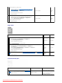
Printing on Letterhead
Check with the manufacturer or vendor to determine whether the pre-printed letterhead you have selected is acceptable for laser printers.
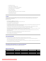
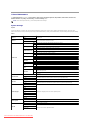
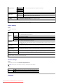
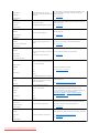
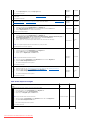
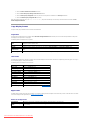
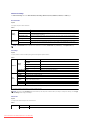
Page orientation is important when printing on letterhead. Use the following table for help when loading letterhead in the print media sources.
Print media source
Print side
Page orientation
Face up
Standard 250-Sheet Tray
Letterhead enters the printer last
Optional 250-Sheet Feeder
Face down
Single Sheet Feeder
Letterhead enters the printer first
Selecting Pre-Punched Paper
Pre-punched paper brands can differ in the number and placement of holes and in manufacturing techniques. However, it may not be possible to print on the
paper to depending on the placement of holes on the paper.
To select and use pre-punched paper:
l
Test paper from several manufacturers before ordering and using large quantities of pre-punched paper.
l
Paper should be punched at the paper manufacturer and not drilled into paper already packaged in a ream. Drilled paper can cause jams when multiple
sheets feed through the printer. This may result in a paper jam.
l
Pre-punched paper can include more paper dust than standard paper. Your printer may require more frequent cleaning and feed reliability may not be
as good as standard paper.
l
Weight guidelines for pre-punched paper are the same as non-punched paper.
Envelopes
Depending on the choice of envelopes, it is possible to expect variable levels of light wrinkling. Before buying large quantities of any print media, it is
recommended that you try a sample first. See "Loading Print Media in the Standard 250-Sheet Tray and Optional 250-Sheet Feeder" or "Loading the Single
Sheet Feeder" for instructions on loading an envelope.
When printing on envelopes:
l
Use only high-quality envelopes that are designed for use in laser printers.
l
Set the print media source to the single sheet feeder or standard 250-sheet tray. Set the paper type to Envelope, and select the correct size of
envelope from the printer driver.
l
For best performance, use envelopes made from 75 g/m2 (20 lb bond) paper. You can use up to 105 g/m2 (28 lb bond) weight for the envelope feeder
as long as the cotton content is 25% or less. Envelopes with 100% cotton content must not exceed 90 g/m2 (24 lb bond) weight.
l
Use only freshly unpackaged, undamaged envelopes.
l
Use envelopes that can withstand temperatures of 205°C (401°F) without sealing, excessive curling, wrinkling, or releasing hazardous emissions. If you have any doubts about the envelopes you are considering, check with the envelope supplier.
l
Adjust the guide to fit the width of the envelopes.
l
To load envelope in the single sheet feeder, insert the envelope with the flaps closed and the short-edge of the envelope facing into the printer. The
print side must be facing down.
l
See "Loading Print Media in the Standard 250-Sheet Tray and Optional 250-Sheet Feeder" or "Loading the Single Sheet Feeder" for instructions on
loading an envelope.
l
Use one envelope size during a print job.
l
Ensure the humidity is low because high humidity (more than 60%) and the high printing temperatures may seal the envelopes.
l
For best performance, do not use envelopes that:
Downloaded from ManualsPrinter.com Manuals
¡
Have excessive curl or twist
¡
Are stuck together or damaged in any way
¡
Contain windows, holes, perforations, cutouts, embossing
¡
Use metal clasps, string ties, or metal folding bars
¡
Have an interlocking design
¡
Have postage stamps attached
¡
Have any exposed adhesive when the flap is in the sealed or closed position
¡
Have nicked edges or bent corners
¡
Have rough, cockle, or laid finishes
Labels
Your printer can print on many labels designed for use with laser printers. Label adhesives, face sheet (printable stock), and topcoats must be able to
withstand temperatures of 205°C (401°F) and pressure of 25 pounds per square inch (psi). Before buying large quantities of any print media, it is recommended that you try a sample first.
When printing on labels:
l
Set the paper type to Label from the printer driver.
l
Do not load labels together with paper in the same tray. This may result in a jam.
l
Do not use label sheets with a slick backing material.
l
Do not print within 1 mm (0.04 inches) of the die cut.
l
Use full label sheets. Partial sheets may cause labels to peel off during printing, resulting in a jam. Partial sheets also contaminate your printer and your
cartridge with adhesive, and could void your printer and cartridge warranties.
l
Use labels that can withstand temperatures of 205°C (401°F) without sealing, excessive curling, wrinkling, or releasing hazardous emissions.
l
Do not print within 1 mm (0.04 inches) of the edge of the label, of the perforations, or between die-cuts of the label.
l
Do not use label sheets that have adhesive to the edge of the sheet. It is recommended that zone coating of the adhesive is done at least 1 mm (0.04
inches) away from the edges. Adhesive material contaminates your printer and could void your warranty.
l
If zone coating of the adhesive is not possible, a 3 mm (0.125 inches) strip should be removed on the leading and driver edge, and a non-oozing
adhesive should be used.
l
Remove a 3 mm (0.125 inches) strip from the leading edge to prevent labels from peeling inside the printer.
l
Portrait orientation is preferred, especially when printing bar codes.
l
Do not use labels that have exposed adhesive.
Storing Print Media
For proper print media storage, the following guidelines help avoid media feeding problems and uneven print quality.
l
For best results, store print media in an environment where the temperature is approximately 21°C (70°F) and the relative humidity is 40%.
l
Store cartons of print media on a pallet or shelf, rather than directly on the floor.
l
If you store individual packages of print media out of the original carton, ensure that they rest on a flat surface so that the edges do not buckle or curl.
l
Do not place anything on top of the print media packages.
Identifying Print Media Sources and Specifications
The following tables provide information on standard and optional print media sources.
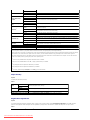
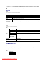
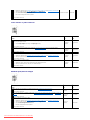
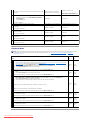
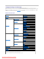
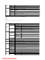
Supported Paper Sizes
Single Sheet Feeder
Standard 250-Sheet Tray
Optional 250-Sheet Feeder
Duplexer
A4 (210x297 mm)
Y
Y
Y
Y
B5 (182x257 mm)
Y
Y
Y
N
A5 (148x210 mm)
Y
Y
Y
N
C5 (162x229 mm)
Y
Y
N
N
Monarch (3.875x7.5 in)
Y
Y
N
N
Downloaded from ManualsPrinter.com Manuals
Monarch LEF (7.5x3.875 in)*1
N
Y
N
N
Envelope #10 (4.125x9.5 in)
Y
Y
N
N
DL (110x220 mm)
Y
Y
N
N
DL LEF (220x110 mm)*1
N
Y
N
N
Letter (8.5x11 in)
Y
Y
Y
Y
Legal (8.5x14 in)
Y
Y
Y
Y
Folio (8.5x13 in)
Y
Y
Y
Y
Executive (7.25 x 10.5 in)
Y
Y
Y
N
Custom*2 * 3
Y
Y
N
N
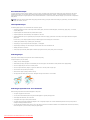
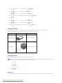
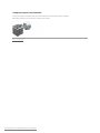
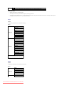
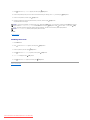
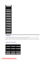
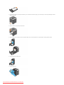
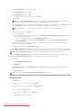
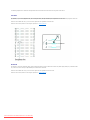
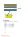
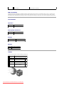
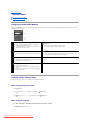
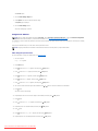
* 1 You can load the paper in two kinds of the paper orientation, the short-edge feed (SEF) and the long edge feed (LEF). The SEF is the paper orientation
that is load the paper into the printer from short edge. The LEF is the paper orientation that is load the paper into the printer from long edge. The following
illustration shows SEF and LEF. The arrow mark in the illustration shows the orientation of the paper loading.
* 2 Custom width: 76.2 mm (3.00 inches) to 215.9 mm (8.5 inches)
Custom length: 127 mm (5.00 inches) to 355.6 mm (14.00 inches)
* 3 Only the administrator user can set the custom size from the printer driver.
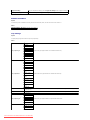
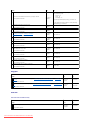
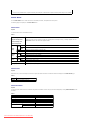
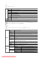
Supported Paper Types
Media
Single Sheet Feeder Standard 250-Sheet Tray Optional 250-Sheet Feeder Duplexer
Plain
Y*
Y*
Y*
Y*
Plain Side 2
Y
Y
Y
N
Plain Thick
Y
Y
Y
Y
Plain Thick Side 2 Y
Y
Y
N
Recycled
Y
Y
Y
Y
Recycled Side 2
Y
Y
Y
N
Label
Y
Y
N
N
Covers
Y
Y
N
N
Covers Thick
Y
Y
N
N
Envelope
Y
Y
N
N
Coated
Y
N
N
N
Coated Thick
Y
N
N
N
* Values marked by an asterisk (*) are the factory default menu settings.
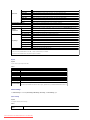
Paper Type Specifications
Paper type
Plain Paper
Weight (gsm)
60-90
Remarks
-
Plain Thick Paper 80/90-105
-
Covers
106-163
-
Covers Thick
164-216
-
Coated
106-163
Inkjet printer paper cannot be used.
Coated Thick
164-216
Inkjet printer paper cannot be used.
Label
3R97408
Inkjet printer paper cannot be used.
Envelopes
-
-
Recycled
-
-
Back to Contents Page
Downloaded from ManualsPrinter.com Manuals
Downloaded from ManualsPrinter.com Manuals
Back to Contents Page
Loading Print Media
Standard 250-Sheet Tray and Optional 250-Sheet Feeder
Loading Print Media in the Standard 250-Sheet Tray and Optional 250-Sheet Feeder
Single Sheet Feeder
Loading the Single Sheet Feeder
Using the Duplex Function
Using the Output Tray
Using the Output Tray Extension
Loading print media properly helps prevent jams and ensures trouble-free printing.
Before loading print media, identify the recommended print side of the print media. This information is usually on the print media package.
Standard 250-Sheet Tray and Optional 250-Sheet Feeder
Capacity
The standard 250-sheet tray and optional 250-sheet feeder can hold:
l
250 sheets of the standard paper.
Print Media Dimensions
The standard 250-sheet tray accepts print media within the following dimensions:
l
Width - 76.2 mm (3.00 inches) to 215.9 mm (8.5 inches)
l
Length - 127 mm (5.00 inches) to 355.6 mm (14.00 inches)
The optional 250-sheet feeder accepts print media within the following dimensions:
l
Width - 148 mm (5.82 inches) to 215.9 mm (8.5 inches)
l
Length - 210 mm (8.27 inches) to 355.6 mm (14.00 inches)
Loading Print Media in the Standard 250-Sheet Tray and Optional 250-Sheet Feeder
NOTE: To avoid paper jams, do not remove the tray while printing is in progress.
NOTE: Use only laser print media. Do not use ink jet paper in this printer.
All trays are loaded the same way.
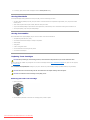
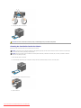
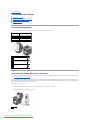
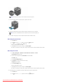
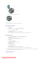
1.
Pull the tray out of the printer about 200 mm. Hold the tray with both hands, and remove it from the printer.
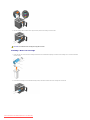
2.
Adjust the paper guides.
Downloaded from ManualsPrinter.com Manuals
NOTE: When you feed paper from the tray loaded with Legal size paper, extend the rear side of the tray.
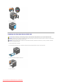
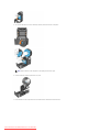
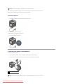
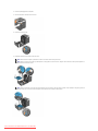
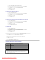
3.
Before loading the print media, flex the sheets back and forth, and then fan them. Straighten the edges of the stack on a level surface.
4.
Place the print media into the tray with the recommended print side facing up.
NOTE: Do not exceed the maximum fill line in the tray. Overfilling the tray may cause paper jams.
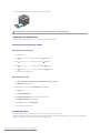
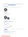
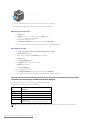
5.
Adjust the width guides and length guides until they rest lightly against the edges of the stack of paper.
NOTE: When loading user-specified print media, adjust the width guides and slide the extendable part of the tray by squeezing the length guide
and sliding it until it rests lightly against the edge of the stack of paper.
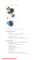
6.
7.
8.
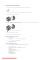
After confirming that the guides are securely adjusted, insert the tray into the printer.
Select the paper type from the operator panel if any print media other than plain print media is loaded. If a user-specified print media is loaded in the
standard 250-sheet tray, you must specify the paper size setting by using the operator panel.
Press Menu button.
Downloaded from ManualsPrinter.com Manuals
9.
Press
or
button until Tray Settings appears, and then press
(Set) button.
or
button until Tray 1 appears, and then press
or
button until Paper Type appears, and then press
or
button until the desired paper types appears, and then press
10.
Press
(Set) button.
11.
Press
(Set) button.
12.
Press
(Set) button.
13.
Press
button.
14.
Press
or
button until Paper Size appears, and then press
(Set) button.
or
button until Custom Size appears, and then press
or
button until the desired paper size appears, and then press
15.
Press
(Set) button.
16.
Press
(Set) button.
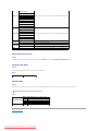
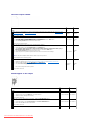
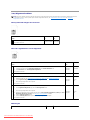
Loading Letterhead
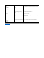
When using the standard 250-sheet tray or optional 250-sheet feeder, the letterhead enters the printer last with the print side facing up.
When using the single sheet feeder, the letterhead enters the printer first with the print side facing down.
Print media source
Print side
Page orientation
Face up
Standard 250-Sheet Tray
Letterhead enters the printer last
Optional 250-Sheet Feeder
Face down
Single Sheet Feeder
Letterhead enters the printer first
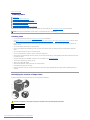
Loading Envelopes
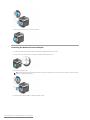
Use the following guidelines when loading envelopes in the standard 250-sheet tray:
NOTE: If you do not load envelopes in the standard 250-sheet tray right after they have been removed from the packaging, they may bulge. To avoid
jams, flatten them as shown below before loading them in the standard 250-sheet tray.
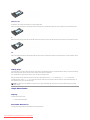
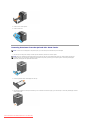
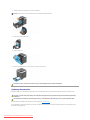
Envelope#10
Load the envelopes short edge feed with the flaps closed and the print side up. Ensure that the flaps come at the right when you face towards the printer.
Downloaded from ManualsPrinter.com Manuals
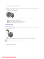
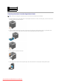
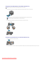
Monarch or DL
The Monarch or DL envelopes can be loaded in one of the following ways:
Load the envelopes short edge feed with the flaps closed and the print side up. Ensure that the flaps come at the right when you face towards the printer.
OR
Load the envelopes long edge feed (LEF) with the flaps open and the print side up. Ensure that the flaps come at the top when you face towards the printer.
C5
Load the envelopes short edge feed with the flaps closed and the print side up. Ensure that the flaps come at the bottom when you face towards the printer.
Linking Trays
Tray linking allows you to load the same size and type of print media in the standard 250-sheet tray and optional 250-sheet feeder. The printer automatically
links the trays and will use the first tray until it runs out of media, then switch to the linked tray.
If you load the same size print media in each tray, ensure that the type of media is same.
When the selected trays are loaded with the same size and type of print media, select the Paper Type settings in the Tray Settings for each source.
To disable tray linking, set the Paper Type to a unique value in each one of the trays. If all trays do not have the same type of print media when linked, you
could mistakenly print a job on the wrong paper type.
NOTE: If the paper type is not specified in the printer driver, the printer automatically links the trays (even if there are different types of print media
loaded in them).
Single Sheet Feeder
Capacity
The single sheet feeder can hold:
l
1 sheet of the standard paper.
Print Media Dimensions
The single sheet feeder accepts print media within the following dimensions:
Downloaded from ManualsPrinter.com Manuals
l
Width - 76.2 mm (3.00 inches) to 215.9 mm (8.5 inches)
l
Length - 127 mm (5.00 inches) to 355.6 mm (14.00 inches)
Loading the Single Sheet Feeder
1.
Adjust the width guides to the print media's width.
2.
Hold both sides of the print media facing down close to the single sheet feeder, and push it into the printer until it automatically feeds.
NOTE: Do not force the print media into the single sheet feeder.
NOTE: Load letterhead face-down, with the top of the sheet entering the printer first.
NOTE: If you experience problems with paper feed, turn the paper around.
Loading an Envelope
Envelope#10, Monarch, or DL
To load an envelope into the single sheet feeder, insert the envelope short edge feed with the flap closed and the print side down. Ensure that the flap comes
at the right when you face towards the printer.
NOTICE: Never use envelopes with windows, coated linings, or self-stick adhesives. These lead to paper jams and can damage the printer.
NOTE: Ensure that you load an envelope with the flap completely closed.
NOTE: Insert an envelope with the flap side face up and with the stamp area on the top right side.
C5
To load an envelope into the single sheet feeder, insert the envelope short edge feed with the flap open and the print side down. Ensure that the flap comes
at the bottom when you face towards the printer.
Downloaded from ManualsPrinter.com Manuals
NOTICE: Never use envelopes with windows, coated linings, or self-stick adhesives. These lead to paper jams and can damage the printer.
NOTE: Ensure that you load an envelope with the flap completely opened.
NOTE: Insert an envelope with the flap side face up and with the stamp area on the bottom right side.
Using the Duplex Function
Duplex printing (or two-sided printing) allows you to print on both sides of a sheet of paper automatically. Duplex printing is only available when the optional
duplexer is installed on the printer. For information on how to install the duplexer, see "Installing a Duplexer". For sizes that are acceptable for duplexer, see
"Supported Paper Sizes".
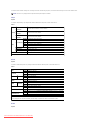
Using Booklet Print
To use booklet print, you must select either Flip on Short Edge or Flip on Long Edge from the Duplex menu in the printer properties dialog box and then
select Booklet Creation in the Booklet/Poster/Mixed Document dialog box displayed by clicking the Booklet/Poster/Mixed Document button. From the
Duplex menu, you can define the way 2-sided print pages are bound, and how the printing on the back of the sheet (even-numbered pages) is oriented in
relation to the printing on the front (odd-numbered pages).
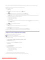
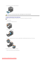
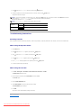
Assumes binding along the long edge of the page (left edge for portrait orientation and top edge for landscape orientation). The following
illustration shows long-edge binding for portrait and landscape pages:
Flip on Long
Edge
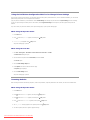
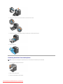
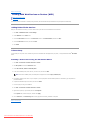
Assumes binding along the short edge of the page (top edge for portrait orientation and left edge for landscape orientation). The following
illustration shows short-edge binding for portrait and landscape pages:
Flip on Short
Edge
Using the Output Tray
The output tray holds up to:
l
150 sheets of plain paper
Downloaded from ManualsPrinter.com Manuals
Using the Output Tray Extension
The output tray extension is designed to prevent print media from falling from the printer after the print job is complete.
Before printing a document, ensure the output tray extension is fully extended.
Back to Contents Page
Downloaded from ManualsPrinter.com Manuals
Back to Contents Page
Printer Settings
Printing a Printer Settings Page
Using the Operator Panel to Change Printer Settings
Using the Tool Box to Change the Printer Settings
Using the Dell Printer Configuration Web Tool to Change Printer Settings
Resetting Defaults
Initializing NVRAM for Network Settings
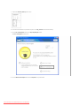
You can change most system settings from your software programs. If your printer is attached to the network, you can change settings from the Dell Printer
Configuration Web Tool. To launch the Dell Printer Configuration Web Tool, type the printer's IP address in your Web browser. To find your printer's IP
address, see "Printing a Printer Settings Page".
Settings from the software program update the default printer settings for the printer. Settings from the printer driver only apply to the job you are sending to
the printer.
If you cannot change a setting from your software program, use the operator panel, Tool Box or the Dell Printer Configuration Web Tool. Changing a printer
setting from the operator panel, Tool Box or from the Dell Printer Configuration Web Tool makes that setting the user default.
Printing a Printer Settings Page
You can verify the detailed printer settings by printing a printer settings page.
When Using the Operator Panel
1.
Press Menu button.
2.
Press
button until Report/List appears, and then press
(Set) button.
3.
Printer Setting is displayed. Press
(Set) button.
The printer settings page is printed.
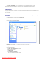
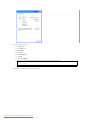
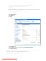
When Using the Tool Box
1.
Click start® All Programs® Dell Printers® Dell 2130cn Color Laser Printer® Tool Box.
The Select Printer dialog box opens.
2.
Click the name of this printer listed in Printer Name, and then click OK.
The Tool Box opens.
3.
Click the Printer Settings Report tab.
4.
Select Reports from the list at the left side of the page.
The Reports page is displayed.
5.
Click the Printer Settings button.
The printer settings page is printed.
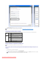
Using the Operator Panel to Change Printer Settings
You can select menu items and corresponding values from the operator panel.
When you first enter the menus from the operator panel, you see an asterisk (*) next to a value in the menus.
This asterisk indicates the factory default menu setting. These settings are the original printer settings.
NOTE: Factory defaults may vary for different countries.
Downloaded from ManualsPrinter.com Manuals
When you select a new setting from the operator panel, an asterisk appears next to the setting to identify it as the current user default menu setting.
These settings are active until new ones are selected or the factory defaults are restored.
To select a new value as a setting:
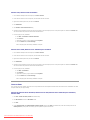
1.
Press Menu button.
2.
Press
or
button until the desired menu appears, and then press
(Set) button.
or
button until the desired menu or menu item appears, and then press
3.
Press
(Set) button.
l
If the selection is a menu, the menu is opened and the first system setting in the menu appears.
l
If the selection is a menu item, the default menu setting for the menu item appears. (The current user default menu setting has an asterisk (*)
beside it.)
Each menu item has a list of values for the menu item. A value can be:
4.
l
A phrase or word to describe a setting
l
A numerical value that can be changed
l
An On or Off setting
l
Press
or
buttons at the same time. This will restore the factory default menu settings. Press
factory default menu settings.
Press
or
(Set) button to return the settings to the
button to scroll until the desired value appears.
5.
Press
(Set) button.
This enables the setting value, which is indicated by an asterisk (*) next to the setting value.
6.
Press Cancel or
button to return to the previous menu.
To continue setting other items, select the desired menu. To quit setting new values, press Cancel button.
Driver settings may override changes previously made and may require you to change the operator panel defaults.
Using the Tool Box to Change the Printer Settings
You can select menu items and corresponding values from the Tool Box.
NOTE: Factory defaults may vary for different countries.
These settings are active until new ones are selected or the factory defaults are restored.
To select a new value as a setting:
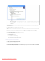
1.
Click start® All Programs® Dell Printers® Dell 2130cn Color Laser Printer® Tool Box.
The Select Printer dialog box opens.
2.
Click the name of this printer listed in Printer Name, and then click OK.
The Tool Box opens.
3.
Click the Printer Maintenance tab.
4.
Select the desired menu item.
Each menu item has a list of values for the menu item. A value can be:
5.
l
A phrase or word to describe a setting
l
A numerical value that can be changed
l
An On or Off setting
Select the desired value, and then click the associated button with each menu item.
Driver settings may override changes previously made and may require you to change the Tool Box defaults.
Downloaded from ManualsPrinter.com Manuals
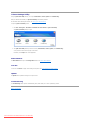
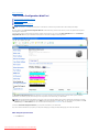
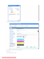
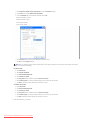
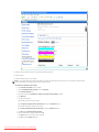
Using the Dell Printer Configuration Web Tool to Change Printer Settings
If your printer is connected to the network, you can change the device settings from your Web browser. If you are a network administrator, you can clone the
printer settings of one printer to one or all printers on the network.
Type your printer's IP address in your Web browser. Choose Printer Settings from the topics list, and then select the System Settings you want to change.
To copy your printer settings to another printer on the network, choose Copy Printer Settings from the topics list, and then type the other printer's IP
address.
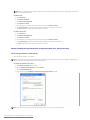
If you do not know your printer's IP address, see the printer settings page. To print a printer settings page:
When Using the Operator Panel
1.
Press Menu button.
2.
Press
button until Report/List appears, and then press
(Set) button.
3.
Printer Setting is displayed. Press
(Set) button.
The printer settings page is printed.
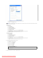
When Using the Tool Box
1.
Click start® All Programs® Dell Printers® Dell 2130cn Color Laser Printer® Tool Box.
The Select Printer dialog box opens.
2.
Click the name of this printer listed in Printer Name, and then click OK.
The Tool Box opens.
3.
Click the Printer Settings Report tab.
4.
Select Reports from the list at the left side of the page.
The Reports page is displayed.
5.
Click the Printer Settings button.
The printer settings page is printed.
Resetting Defaults
After executing this function and rebooting the printer, all the menu parameters, except the parameters for the network, are reset to their default values.
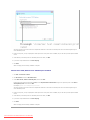
When Using the Operator Panel
1.
Press Menu button.
2.
Press
button until Admin Menu appears, and then press
(Set) button.
3.
Press
button until Maintenance appears, and then press
(Set) button.
4.
Press
button until Reset Defaults appears, and then press
(Set) button.
5.
The Are you sure? message appears on the operator panel. Press
6.
Turn off the printer, and then on again to apply the settings.
Downloaded from ManualsPrinter.com Manuals
(Set) button.
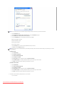
When Using the Tool Box
1.
Click start® All Programs® Dell Printers® Dell 2130cn Color Laser Printer® Tool Box.
The Select Printer dialog box opens.
2.
Click the name of this printer listed in Printer Name, and then click OK.
The Tool Box opens.
3.
Click the Printer Maintenance tab.
4.
Select Reset Defaults from the list at the left side of the page.
The Reset Defaults page is displayed.
5.
Click the Start button.
The printer is turned off automatically to apply the settings.
Initializing NVRAM for Network Settings
You can initialize the IP address and network-related settings by initializing NVRAM for Network settings.
1.
Press Menu button.
2.
Press
button until Admin Menu appears, and then press
(Set) button.
3.
Press
button until Network appears, and then press
(Set) button.
4.
Press
button until Reset LAN appears, and then press
(Set) button.
5.
The Are you sure? message appears on the operator panel. Press
6.
Turn off the printer, and then on again to apply the settings.
Back to Contents Page
Downloaded from ManualsPrinter.com Manuals
(Set) button.
Back to Contents Page
Understanding the Tool Box Menus
Printer Settings Report
Printer Maintenance
Diagnosis
The Tool Box allows you to view or specify the printer settings. You can also diagnose the printer settings by using the Tool Box.
The Tool Box consists of the Printer Settings Report, Printer Maintenance, and Diagnosis tabs.
NOTE: A Password dialog box appears the first time you try to change settings on ToolBox when Panel Lock is set on the printer. In this case, input
the password you specified, and click OK to apply the settings.
Printer Settings Report
The Printer Settings Report tab includes the Printer Information, Menu Settings, Reports, Network Settings, and TCP/IP Settings pages.
NOTE: Values marked by an asterisk (*) are the factory default menu settings.
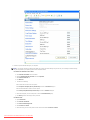
Printer Information
Purpose:
To display the printer's system information.
Values:
Dell Service Tag Number
Displays Dell's service tag number.
Printer Serial Number
Displays the printer's serial number.
Printer Type
Displays the type of printing for the printer. Color Laser is displayed normally.
Asset Tag Number
Displays the printer's asset tag number.
Memory Capacity
Displays the memory capacity.
Processor Speed
Displays the processing speed.
Firmware Version
Displays the version of the controller.
Network Firmware Version
Displays the NIC version.
MCU Firmware Version
Displays the version of the MCU firmware.
Printing Speed (Color)
Displays the speed for color printing.
Printing Speed (Monochrome) Displays the speed for monochrome printing.
Menu Settings
Purpose:
To display the printer's menu settings.
Values:
Power Saver Timer
Mode 1
Displays the amount of time before the printer enters the power saver timer mode 1 after it finishes a
job.
Power Saver Timer
Mode 2
Displays the amount of time before the printer enters the power saver timer mode 2 after it goes into the
power saver timer mode 1.
Control Panel Tone
Displays whether to emit the tone when the operator panel input is correct. Off indicates that the tone is
disabled.
Invalid Key Tone
Displays whether to emit the tone when the operator panel input is incorrect. Off indicates that the tone
is disabled.
Machine Ready Tone
Displays whether to emit the tone when the printer becomes ready. Off indicates that the tone is
disabled.
Job Complete Tone
Displays whether to emit the tone when a job is complete. Off indicates that the tone is disabled.
Fault Tone
Displays whether to emit the tone when a job ends abnormally. Off indicates that the tone is disabled.
Alert Tone
Displays whether to emit the tone when a problem occurs. Off indicates that the tone is disabled.
Out of Paper Alert
Tone
Displays whether to emit the tone when the printer runs out of paper. Off indicates that the tone is
disabled.
Low Toner Alert Tone
Displays whether to emit the tone when the toner or some other consumable is low. Off indicates that
the tone is disabled.
Downloaded from ManualsPrinter.com Manuals
Base Tone
Displays whether to emit the tone when the operator panel is returned to the default by scrolling the
loop menu. Off indicates that the tone is disabled.
Fault Time-Out
Displays the amount of time the printer cancels for a job stops abnormally.
Time-Out
Displays the amount of time the printer waits for data to arrive from the computer.
Panel Language
Displays the language to be used on the operator panel.
Auto Log Print
Displays whether the printer outputs a log of completed jobs from the printer automatically.
Print ID
Displays where to print a user ID on the output paper.
Print Text
Displays whether the printer outputs PDL (Page Description Language) data, which is not supported by
the printer, as text when the printer receives it.
Banner Sheet Insert
Position
Displays where to insert a banner sheet.
Banner Sheet Specify
Tray
Displays which input tray to use to insert a banner sheet.
RAM Disk
Displays whether to allocate RAM for the file system for the Secure Print and Proof Print features.
This item is only available when the 512 MB, or higher, optional memory is installed.
Odd Page 2 Sided
Displays how the odd last page is printed when using duplex printing.
Substitute Tray
Displays whether to use another size paper when the paper that is loaded in the specified tray does not
match the paper size settings for the current job.
mm/inch
Displays the measurement unit used on the operator panel.
Plain
Displays the plain paper density settings.
Label
Displays the label paper density settings.
Auto Registration
Adjustment
Auto Registration
Adjustment
Displays whether to automatically adjust color registration.
Adjust Altitude
Adjust Altitude
Displays the altitude of the location where the printer is installed.
Non-Dell Toner
Non-Dell Toner
Displays whether or not to use another manufacturer's toner cartridge.
Tray 1 Paper Type
Displays the paper type setting of the standard 250-sheet tray.
Tray 1 Paper Size
Displays the paper size setting of the standard 250-sheet tray.
System Settings
Paper Density
Tray 1 Custom Size - Y Displays the length of custom size paper loaded in the standard 250-sheet tray.
Tray Settings
Tray 1 Custom Size - X
Displays the width of custom size paper loaded in the standard 250-sheet tray.
Tray 2 Paper Type* 1
Displays the paper type setting of the optional 250-sheet feeder.
Tray 2 Paper Size* 1
Displays the paper size setting of the optional 250-sheet feeder.
Display Popup
Displays a popup menu that prompts to set the paper size and type when paper is loaded in the
standard 250-sheet tray or optional 250-sheet feeder.
* 1 This item is only available when the optional 250-sheet feeder is installed.
Reports
Purpose:
To print the printer's settings and history information.
The reports are printed in the paper size specified in printer settings. The default is A4 or Letter.
Values:
Printer Settings Click to print a detailed list of the printer settings.
Panel Settings
Click to print a detailed list of the panel settings.
Job History
Click to print the printer's Completed Jobs history.
Error History
Click to print the printer's error history.
Print Meter
Click to print the print meter.
Color Test Page Click to print a color test page.
TCP/IP Settings
Purpose:
To display the current settings of TCP/IP (Transmission Control Protocol/Internet Protocol) protocol.
Values:
IP Address Mode
Displays the method for acquiring the IP address.
IP Address
Displays the printer's IP address.
Subnet Mask
Displays the subnet mask.
Gateway Address Displays the gateway address.
Downloaded from ManualsPrinter.com Manuals
Printer Maintenance
The Printer Maintenance tab includes the System Settings, Paper Density, Registration Adjustment, Adjust Altitude, Reset Defaults, Non-Dell Toner,
Initialize PrintMeter, Tray Settings, TCP/IP Settings, and Network Settings pages.
NOTE: Values marked by an asterisk (*) are the factory default menu settings.
System Settings
Purpose:
To Use these settings to configure the printer's power management, warning tones, time-out time, operator panel language setting, job log auto print,
position of the Print ID, setting of the dump print, setting of the additional memory, setting of the substitute sheet, mm/inch setting, and duplex print settings.
Values:
Power Saver Timer
Mode 1* 1
1-30 Min.
Power Saver Timer
Mode 2* 1
5-60 Min.
Specifies the time before the printer enters the power saver timer mode 1(sleep mode) after it
finishes a job.
3 Min.*
Specifies the time before the printer enters the power saver timer mode 2 (deep sleep mode) after
it goes into the power saver timer mode 1.
10 Min*
Off*
Does not emit a tone when the operator panel input is correct.
On
Emits a tone when the operator panel input is correct.
Off*
Does not emit a tone when the operator panel input is incorrect.
On
Emits a tone when the operator panel input is incorrect.
Off*
Does not emit a tone when the printer becomes ready.
On
Emits a tone when the printer becomes ready.
Off*
Does not emit a tone when a job is complete.
On
Emits a tone when a job is complete.
Off*
Does not emit a tone when a job ends abnormally.
On
Emits a tone when a job ends abnormally.
Off*
Does not emit a tone when a problem occurs.
On
Emits a tone when a problem occurs.
Out of Paper Alert
Tone
Off*
Does not emit a tone when the printer runs out of paper.
On
Emits a tone when the printer runs out of paper.
Low Toner Alert
Tone
Off*
Does not emit a tone when toner or some other consumable is low.
On
Emits a tone when toner or some other consumable is low.
Off*
Does not emit a tone when the operator panel display is returned to the default settings by
scrolling the loop menu.
On
Emits a tone when the operator panel display is returned to the default settings by scrolling the
loop menu.
Control Panel Tone
Invalid Key Tone
Machine Ready Tone
Job Complete Tone
Fault Tone
Audio Tones
Alert Tone
Base Tone
0
Fault Time-Out
Disables the fault time-out.
3-300 sec
Specifies the amount of time the printer cancels for a job stops abnormally.
60 sec*
0
Time-Out
Disables the job time-out.
5-300 sec
Specifies the amount of time before the printer cancels for jobs that stop abnormally.
30 sec*
English*
French
Italian
German
Panel Language
Spanish
Specifies the language to be used on the operator panel.
Dutch
Danish
Norwegian
Swedish
Off*
Does not automatically output a log of completed jobs from the printer.
On
Outputs a log of completed jobs from the printer automatically.
Off*
Does not print the user ID.
Auto Log Print
Top Left
Print ID
Top Right
Prints the user ID on the specified location.
Bottom Left
Downloaded from ManualsPrinter.com Manuals
Bottom Right
Off
Does not print the received PDL data as text data.
On*
Prints the received PDL data as text data.
Off*
Does not insert the banner sheet.
Print Text
Banner Sheet Insert
Position
Front
Back
Inserts the banner sheet to the specified position.
Front & Back
Banner Sheet Specify
Tray
Tray 1*
Specifies the input tray to insert the banner sheet.
Tray 2*2
Does not allocate RAM for the disk file system. Secure Print, and Proof Print jobs will abort and be
recorded to the job log.
Disable
RAM Disk*
3
50–500MB*4
50–1000MB*5
Allocates RAM for the disk file system automatically.
1 Sided*
Prints the odd last page upside down to the paper.
2 Sided
Prints the odd last page in normal direction to the paper.
Off
No tray size substitute accepted.
Larger Size
Substitutes paper of next largest size. When there is no larger paper size, the printer substitutes
paper of nearest size.
Nearest Size*
Substitutes paper of nearest size.
Odd Page 2 Sided
Substitute Tray
millimeter (mm)*
mm/inch
Selects millimeter or inch as the default measurement unit.
inch (") *6
Apply New Settings
After you complete the settings, press the Apply New Settings button to apply the changes.
Restart printer to apply new settings
Press the Restart printer to apply new settings button to apply the changes.
* 1 Enter 3 to put the printer in the power saver timer mode three minutes after it finishes a job. This uses much less energy, but requires more warm-up
time for the printer. Enter 3 if your printer shares an electrical circuit with room lighting and you notice lights flickering.
Select a high value if your printer is in constant use. Under most circumstances, this keeps the printer ready to operate with minimum warm-up time. Select a
value between 1 and 30 minutes for the power saver timer mode if you want a balance between energy consumption and a shorter warm-up period.
The printer automatically returns to the standby mode from the power saver timer mode when it receives data from the computer. You can also return the
printer to the standby mode by pressing any button on the operator panel.
* 2 This item is only available when the optional 250-sheet feeder is installed.
* 3 This item is only available when the 512 MB, or higher, optional memory is installed.
* 4 Only displayed when the optional 512 MB memory is installed.
* 5 Only displayed when the optional 1024 MB memory is installed.
* 6 The factory default setting of mm/inch is set to inch(") in the United States.
Paper Density
Purpose:
To specify the paper density settings.
Values:
Normal*
Plain
Specifies plain paper density settings.
Light
Normal*
Label
Specifies label paper density settings.
Light
Apply New Settings
After you complete the settings, press the Apply New Settings button to apply the changes.
Restart printer to apply new settings Press the Restart printer to apply new settings button to apply the changes.
Registration Adjustment
Purpose:
To set Color Registration Adjustment (individual yellow, magenta, cyan correction) settings. When Auto Registration Adjustment is set to On, the printer
prints the color registration chart and adjusts the color registration by using the chart. This function is required after the printer is set up or moved.
Values:
Downloaded from ManualsPrinter.com Manuals
Off
Does not perform color registration automatically.
On*
Performs color registration automatically.
Auto Registration Adjustment
Auto Correct
Click Start to perform color registration automatically.
Color Regi Chart
Click Start to print a color registration chart.
Yellow
-9+9
0*
-9Color Registration Adjustment
Magenta +9
1 (Lateral)
0*
Specifies lateral (perpendicular to paper feed direction) color adjustment values that are found in the color
registration chart individually for Yellow, Magenta, and Cyan.
-9+9
Cyan
0*
Yellow
-9+9
0*
-9Color Registration Adjustment
Magenta +9
2 (Process)
0*
Cyan
Specifies process (paper feed direction) color adjustment values that are found in the color registration
chart individually for Yellow, Magenta, and Cyan.
-9+9
0*
Apply New Settings
After you complete the settings, press the Apply New Settings button to apply the changes.
Restart printer to apply new settings
Press the Restart printer to apply new settings button to apply the changes.
Adjust Altitude
Purpose:
To specify the altitude of the location where the printer is installed.
The discharge phenomenon for charging the photo conductor varies with barometric pressure. Adjustments are performed by specifying the altitude of the
location where the printer is being used.
Values:
0 meter*
1000 meters
Specifies the altitude of the location where the printer is installed.
2000 meters
3000 meters
Apply New Settings
After you complete the settings, press the Apply New Settings button to apply the changes.
Restart printer to apply new settings Press the Restart printer to apply new settings button to apply the changes.
Reset Defaults
Purpose:
To initialize the NV (nonvolatile) memory for system parameters. After executing this function to automatically restart the printer, the menu parameters, or
data are reset to their default values.
Values:
Start Initializes system parameters.
Non-Dell Toner
When Non-Dell toner cartridge is used, the printer may be severely damaged and may not be covered by your warranty.
Purpose:
To specify whether or not to use another manufacturer's toner cartridge.
Values:
Off*
Disables the use of another manufacturer's toner cartridge.
On
Enables the use of another manufacturer's toner cartridge.
Non-Dell Toner
Downloaded from ManualsPrinter.com Manuals
Apply New Settings
After you complete the settings, press the Apply New Settings button to apply the changes.
Restart printer to apply new settings Press the Restart printer to apply new settings button to apply the changes.
Initialize PrintMeter
Purpose:
To initialize the printer's PrintMeter. Executing this function restarts the printer, and the value of the meter resets to 0.
Values:
Initialize PrintMeter Click Start to initialize the PrintMeter.
Tray Settings
Purpose:
To specify the paper types and sizes for input trays respectively.
Values:
Plain*
Plain Thick
Covers
Covers Thick
Label
Tray 1 Paper Type
Recycled
Specifies the type of paper loaded in the standard 250-sheet tray.
Envelope
Plain S2*1
Plain Thick S2*1
Recycled S2*1
A4 (210 x 297 mm)*
A5 (148 x 210 mm)
B5 (182 x 257 mm)
Letter (8.5 x 11")
Folio (8.5 x 13")
Legal (8.5 x 14")
Executive (7.25 x
10.5")
Tray 1 Paper Size
Monarch (3.875 x
7.5")
Specifies the size of paper loaded in the standard 250-sheet tray.
Monarch LEF (7.5 x
3.875")
DL (110 x 220 mm)
DL LEF (220 x 110
mm)
C5 (162 x 229 mm)
Envelope #10 (4.125
x 9.5")
Custom Size
Tray 1 Custom Size - Y
Specifies the length of custom size paper loaded in the standard 250-sheet tray. The available range is from 127 mm (5.0 in.) to
355 mm (14.0 in.).
Tray 1 Custom Size - X
Specifies the width of custom size paper loaded in the standard 250-sheet tray. The available range is from 77 mm (3.0 in.) to
215 mm (8.5 in.).
Plain*
Plain Thick
Recycled
Tray 2 Paper Type* 2
Plain S2*1
Plain Thick S2*1
Recycled S2*1
A4 (210 x 297 mm)*
A5 (148 x 210 mm)
B5 (182 x 257 mm)
Downloaded from ManualsPrinter.com Manuals
Specifies the type of paper loaded in the optional 250-sheet feeder.
Letter (8.5 x 11")
Tray 2 Paper Size* 2
Specifies the size of paper loaded in the optional 250-sheet feeder.
Folio (8.5 x 13")
Legal (8.5 x 14")
Executive (7.25 x
10.5")
Off
Does not display a popup message that prompts to set paper size and type when paper is loaded in the
standard 250-sheet tray and optional 250-sheet feeder.
On*
Displays a popup message that prompts to set paper size and type when paper is loaded in the
standard 250-sheet tray and optional 250-sheet feeder.
Display Popup
Apply New Settings
After you complete the settings, press the Apply New Settings button to apply the changes.
Restart printer to apply
new settings
Press the Restart printer to apply new settings button to apply the changes.
* 1 "S2" means the print side 2 of the paper.
* 2 This item is only available when the optional 250-sheet feeder is installed.
TCP/IP Settings
Purpose:
To configure TCP/IP settings.
Values:
Automatically sets the IP address.
AutoIP*
IP Address
Mode
A random value in the range of 169.254.1.0 to 169.254.254.255 that is not currently in use on the network is set as the IP
address. The subnet mask is set as 255.255.0.0.
DHCP
Sets the IP address using DHCP.
BOOTP
Sets the IP address using BOOTP.
RARP
Sets the IP address using RARP.
Manually Set
Manually sets the IP address.
Manually sets the IP address allocated to the printer.
IP Address*1
It is allocated to the printer using the format nnn.nnn.nnn.nnn. Each octet that makes up nnn.nnn.nnn.nnn is a value in the
range of 0 to 254.
Manually sets the subnet mask.
Subnet Mask*2
It is specified using the format nnn.nnn.nnn.nnn. Each octet that makes up nnn.nnn.nnn.nnn is a value in the range of 0 to
255.
Manually sets the gateway address.
Gateway Address*1
It is specified using the format nnn.nnn.nnn.nnn. Each octet that makes up nnn.nnn.nnn.nnn is a value in the range of 0 to
254.
Apply New Settings
After you complete the settings, press the Apply New Settings button to apply the changes.
Restart printer to apply new
settings
Press the Restart printer to apply new settings button to apply the changes.
* 1 127 and any value in the range of 224 to 254 cannot be specified for the first octet of a gateway address.
* 2 255.255.255.255 cannot be specified as the subnet mask.
Network Settings
Purpose:
To display the server settings of the Dell Printer Configuration Web Tool.
NOTE: When the printer is connected to the local port, this setting cannot be displayed.
Values:
Display
Displays the server settings of the Dell Printer Configuration Web Tool.
Off
Disable to display the server settings of the Dell Printer Configuration Web Tool.
Display of EWS
On* Enable to display the server settings of the Dell Printer Configuration Web Tool.
Diagnosis
Downloaded from ManualsPrinter.com Manuals
The Diagnosis tab includes the Chart Print, Machine Check, Paper Wrinkle Check Mode, Environment Sensor Info, Developer Stir Mode, and Refresh
Mode pages.
NOTE: Values marked by an asterisk (*) are the factory default menu settings.
Chart Print
Purpose:
To print various charts that can be used for the printer's diagnosis.
Values:
Pitch Configuration Chart
Outputs full halftone pages for yellow, magenta, cyan, and black. Also outputs pages to check the pitch. A total of five pages
are output. The chart is output to A4 or Letter size paper.
Ghost Configuration Chart
Outputs a chart to check for ghost printing. One page is output. The chart is output to A4 or Letter size paper.
4 Colors Configuration
Chart
Bands of yellow, magenta, cyan, and black are output with varying density. One page is output. The chart is output to A4 or
Letter size paper.
MQ Chart
Outputs charts to check for the binding in A4 or Letter.
Alignment Chart
Outputs a chart to check for proper alignment of the print image on the paper. One page is output. The chart is output to A4 or
Letter size paper.
PHD Refresh
Configuration Chart
Outputs a chart to check the light fatigue of the PHD unit. One page is output. The chart is output to A4 or Letter size paper.
Machine Check
Purpose:
To check the operation of the printer's components.
Values:
Main Motor Operation Check* Click Start to operate the main motor inside the printer. Confirm the motor sound.
Machine
Check
Fuser Motor Operation Check
Click Start to operate the fuser motor. Confirm the motor sound.
Feed Roll Operation Check*1
Click Start to operate the feed roll. Confirm the motor sound.
REGI CLUTCH Operation
Check
Click Start to operate the REGI CLUTCH. Confirm that you can hear the clutch clicking.
Dispense Motor Check
(Yellow)
Dispense Motor Check
(Magenta)
Click Start to operate the dispense motor for each toner cartridge. Confirm the motor sound.
Dispense Motor Check (Cyan)
Dispense Motor Check
(Black)
Play of Sound
Plays back through your computer's speakers a recording of the normal sound for the currently selected
Machine Check item.
Start
Click this button to check the operation of the items selected with Machine Check and output the results to
Result.
* 1 When performing the feed roll operation check, remove the standard 250-sheet tray from the printer.
Paper Wrinkle Check Mode
Purpose:
To determine whether or not paper is wrinkled in the fuser.
This function stops printing before the paper enters the fuser. After you remove the paper inside the printer, check the following:
l
If the paper is wrinkled, the wrinkle occurred in the part other than fuser.
l
If the paper is not wrinkled, the wrinkle occurred in the fuser.
Values:
A4 (210 x 297 mm)
A5 (148 x 210 mm)
B5 (182 x 257 mm)
Letter (8.5 x 11")
Downloaded from ManualsPrinter.com Manuals
Folio (8.5 x 13")
Legal (8.5 x 14")
Paper Size
Executive (7.25 x 10.5")
Specifies the size of paper to be used by the Paper Wrinkle Check Mode.
Monarch (3.875 x 7.5")
Monarch LEF (7.5 x 3.875")
DL (110 x 220 mm)
DL LEF (220 x 110 mm)
C5 (162 x 229 mm)
Envelope #10 (4.125 x 9.5")
Plain*
Plain Thick
Covers
Paper Type Covers Thick
Specifies the type of paper to be used by the Paper Wrinkle Check Mode.
Label
Recycled
Envelope
Off*
Does not use the Print side 2 of the paper.
On
Uses the Print side 2 of the paper.
Color*
Prints in color mode.
Black
Prints in monochrome mode.
Rear side
Color Mode
Start
Click this button to print in the specified paper size, type, and color mode.
Environment Sensor Info
Purpose:
To output the printer's internal environment sensor information to Result by pressing the Get Environment Sensor Info button.
Developer Stir Mode
Purpose:
To rotate the developer motor and stir the toner in the toner cartridge.
Values:
Developer Stir Mode Click Start to stir the toner.
Refresh Mode
Purpose:
To use up a toner cartridge or PHD unit when you need to replace it before the end of its life, or to stir the toner in a new toner cartridge.
CAUTION: Using the Refresh Mode consumes extra toner.
Values:
Yellow
Click Yellow to clean the yellow cartridge.
Magenta Click Magenta to clean the magenta cartridge.
Toner Refresh Mode
PHD Refresh Mode
Cyan
Click Cyan to clean the cyan cartridge.
Black
Click Black to clean the black cartridge.
PHD
Click PHD to clean the PHD unit.
Back to Contents Page
Downloaded from ManualsPrinter.com Manuals
Back to Contents Page
Understanding the Printer Menus
Report/List
Admin Menu
Tray Settings
Stored Print
Setting Panel Lock
When your printer is configured as a network printer available to a number of users, the access to the Admin Menu menus can be limited. This prevents other
users from using the operator panel to inadvertently change a printer user default that has been set by the administrator. In this case, you can access the
Stored Print, and Tray Settings menus only.
However, you can use your printer driver to override printer user defaults and select settings for individual print jobs.
To complete print jobs, you may also need to modify tray settings.
Report/List
Use the Report/List menu to print various types of reports and lists.
Printer Setting
Purpose:
To print a list of the current user default values, the installed options, the amount of installed print memory, and the status of printer supplies.
Panel Settings
Purpose:
To print a detailed list of all the settings on the operator panel menus.
PCL Fonts List
Purpose:
To print a sample of the available PCL fonts.
See also:
"Understanding Fonts", "Printing a Font Sample List"
PCL Macro List
Purpose:
To print the information on the downloaded PCL macro.
Job History
Purpose:
To print a detailed list of the print jobs that have been processed. This list contains the last 20 jobs.
Error History
Purpose:
To print a detailed list of paper jams and fatal errors.
Print Meter
Downloaded from ManualsPrinter.com Manuals
Purpose:
To print the reports for the total number of pages printed. When printed using either the printer control panel or Dell Printer Configuration Web Tool, the
report will be titled Print Volume Report.
Color Test Page
Purpose:
To print a page for testing colors.
Stored Document
Purpose:
To print a list of all files that are stored for Secure Print and Proof Print in the RAM disk.
NOTE: The Stored Document is displayed only when the 512 MB or more optional memory is installed on the printer and RAM Disk under System Settings
is enabled.
Admin Menu
Use the Admin Menu menu to configure a variety of printer features.
Network
Use the Network menu to change the printer settings affecting jobs sent to the printer through the wired or wireless network.
NOTE: Values marked by an asterisk (*) are the factory default menu settings.
Ethernet
Purpose:
To specify the communication speed and the duplex settings of Ethernet. Any changes made become effective after the printer is turned off and then on.
Values:
Auto*
Detects the Ethernet settings automatically.
10Base Half
Uses 10base-T half-duplex.
10Base Full
Uses 10base-T full-duplex.
100Base Half Uses 100base-TX half-duplex.
100Base Full
Uses 100base-TX full-duplex.
Status
Purpose:
To display the information on the wireless signal strength. Any change cannot be made on the operator panel to improve the status of the wireless
connection.
Values:
Good
Indicates good signal strength.
Acceptable
Indicates marginal signal strength.
Low
Indicates insufficient signal strength.
No Reception Indicates that no signal is received.
NOTE: This item is only displayed when an optional wireless printer adapter is installed.
Reset Wireless
Purpose:
Downloaded from ManualsPrinter.com Manuals
To initialize wireless network settings. After executing this function and rebooting the printer, all wireless network settings are reset to their default values.
NOTE: This item is only displayed when an optional wireless printer adapter is installed.
TCP/IP
Purpose:
To configure TCP/IP settings. Any changes made become effective after the printer is turned off and then on.
Values:
Uses both IPv4 and IPv6 to set the IP address.
Dual Stack*
IP Mode
Uses IPv4 to set the IP address.
IPv4 Mode
Uses IPv6 to set the IP address.
IPv6 Mode
AutoIP* Automatically sets the IP address.
BOOTP
Uses BOOTP to set the IP address.
Get IP Address RARP
Uses RARP to set the IP address.
DHCP
Uses DHCP to set the IP address.
Panel
Enables the IP address entered on the operator panel.
IPv4
IP Address
Sets the IP address allocated to the printer by using the keys on the operator panel.
Subnet Mask
Sets the subnet mask.
Gateway Address
Sets the gateway address.
IPsec*1
Disables IPsec.
* 1 Only displayed when an optional network protocol adapter is installed and IPsec is enabled.
Protocol
Purpose:
To enable or disable each protocol. Any changes made become effective after the printer is turned off and then on.
Values:
Enable* Enables the LPD port.
LPD
Disable
Disables the LPD port.
Enable* Enables the Port9100 port.
Port9100
Disable
1
NetWare*
Disables the Port9100 port.
Enable* Uses IP for NetWare.
NetWare IP
Disable
Does not use IP for NetWare.
Enable* Enables the WSD port.
WSD*1
Disable
Disables the WSD port.
Enable* Enables the UDP.
SNMP
SNMP UDP
Disable
Disables the UDP.
Enable* Enables the Email Alerts feature.
E-Mail Alert
Disable
Disables the Email Alerts feature.
Enable* Enables an access to Dell Printer Configuration Web Tool embedded in the printer.
EWS
Disable
HTTP-SSL/TLS*2
Disables an access to Dell Printer Configuration Web Tool embedded in the printer.
Enable* Enable the HTTP-SSL/TLS.
Disable
Disable the HTTP-SSL/TLS.
1
* Only displayed when an optional network protocol adapter is installed.
* 2 Only displayed when an optional network protocol adapter is installed and which is authenticated by EWS.
IP Filter
Purpose:
Downloaded from ManualsPrinter.com Manuals
To block data received from certain IP addresses through the wired or wireless network. You can set up to five IP addresses. Any changes made become
effective after the printer is turned off and then on.
Values:
No. n/Address (n is 1-5.)*1
Sets the IP address for Filter n.
No. n/Mask (n is 1-5.)*1
Sets the address mask for Filter n.
Off*
Disable the IP Filter feature for Filter n.
No. n/Mode (n is 1-5.)*1 Accept Accepts an access from the specified IP address.
Reject
Rejects an access from the specified IP address.
* 1 This item is only available for LPD or Port9100.
IEEE 802.1x
Purpose:
To disable the IEEE 802.1x authentication. Any changes made become effective after the printer is turned off and then on.
NOTE: This item is only displayed when the IEEE 802.1x authentication is enabled and the optional network protocol adapter is installed, and also when
the optional wireless printer adapter is not installed.
Reset LAN
Purpose:
To initialize wired network data stored in NV (non-volatile) memory. After executing this function and rebooting the printer, all wired network settings are reset
to their default values.
USB Settings
Use the USB Settings menu to change printer settings affecting a USB port.
NOTE: Values marked by an asterisk (*) are the factory default menu settings.
Port Status
Purpose:
To enable or disable the USB interface. Any changes made become effective after the printer is turned off and then on.
Values:
Enable* The USB interface is enabled.
Disable
The USB interface is disabled.
System Settings
Use the System Settings menu to configure a variety of printer features.
NOTE: Values marked by an asterisk (*) are the factory default menu settings.
PowerSaver Time
Purpose:
To specify the time for transition to power saver mode.
Values:
Mode1 3min.*
Specifies the amount of time before the printer enters the power saver mode 1 after it finishes a job.
1-30min.
10min.*
Mode2
Specifies the amount of time before the printer enters the power saver mode 2 after it goes into the power saver mode 1.
5-60min.
Enter 3 to put the printer in power saver mode three minutes after it finishes a job. This uses much less energy, but requires more warm-up time for the
Downloaded from ManualsPrinter.com Manuals
printer. Enter 3 if your printer shares an electrical circuit with room lighting and you notice lights flickering.
Select a high value if your printer is in constant use. Under most circumstances, this keeps the printer ready to operate with minimum warm-up time. Select a
value between 1 and 30 minutes for power save mode if you want a balance between energy consumption and a shorter warm-up period.
The printer automatically returns to the standby mode from the power saver mode when it receives data from the computer. You can also return the printer to
the standby mode by pressing any button on the operator panel.
Audio Tones
Purpose:
To configure settings for tones emitted by the printer during operation or when a warning message appears.
Values:
Off* Does not emit a tone when the operator panel input is correct.
Control Panel
On
Emits a tone when the operator panel input is correct.
Off* Does not emit a tone when the operator panel input is incorrect.
Invalid Key
On
Emits a tone when the operator panel input is incorrect.
Off* Does not emit a tone when the printer becomes ready.
Machine Ready
On
Emits a tone when the printer becomes ready.
Off* Does not emit a tone when a job is complete.
Job Completed
On
Emits a tone when a job is complete.
Off* Does not emit a tone when a job ends abnormally.
Fault Tone
On
Emits a tone when a job ends abnormally.
Off* Does not emit a tone when a problem occurs.
Alert Tone
On
Emits a tone when a problem occurs.
Off* Does not emit a tone when the printer runs out of paper.
Out of Paper
On
Emits a tone when the printer runs out of paper.
Off* Does not emit a tone when toner or some other consumable is low.
Low Toner Alert
On
Emits a tone when toner or some other consumable is low.
Off* Does not emit a tone when the operator panel display is returned to the default settings by scrolling the loop menu.
Base Tone
On
Emits a tone when the operator panel display is returned to the default settings by scrolling the loop menu.
Fault Time-Out
Purpose:
Specifies in seconds the amount of time the printer should cancel for a job stops abnormally. The print job is cancelled if the time-out time is exceeded.
Values:
60 sec.*
Specifies in seconds the amount of time the printer cancels for a job stops abnormally.
3-300 sec.
Off
Disables the fault timeout.
Time-Out
Purpose:
To specify in seconds the amount of time the printer should wait for data to arrive from the computer. The print job is cancelled if the time-out time is
exceeded.
Values:
30 sec.*
Specifies the amount of time the printer should wait for data to arrive from the computer.
5-300 sec.
Off
Disables the job timeout.
Panel Language
Purpose:
To determine the language of the text on the operator panel screen.
Downloaded from ManualsPrinter.com Manuals
Values:
English*
Français
Italiano
Deutsch
Español
Dansk
Nederlands Norsk
Svenska
Auto Log Print
Purpose:
To automatically print a log of completed jobs after every 20 jobs.
Values:
Off* Does not automatically output a log of completed jobs.
On
Automatically outputs a log of completed jobs.
Print logs can also be printed using the Report/List menu.
NOTE: Restart your printer when you change the settings for the RAM Disk menu.
Print ID
Purpose:
To specify a location where the user ID is printed.
Values:
Off*
Does not print the user ID.
Top Left
Prints the user ID on the top left of the page.
Top Right
Prints the user ID on the top right of the page.
Bottom Left
Prints the user ID on the bottom left of the page.
Bottom Right Prints the user ID on the bottom right of the page.
NOTE: When printing on DL size paper, a part of the user ID may not be printed correctly.
Print Text
Purpose:
To specify whether the printer outputs PDL data, which is not supported by the printer, as text when the printer receives it. Text data is printed on A4 or
Letter size paper.
Values:
On* Prints the received data as text data.
Off
Does not print the received data.
Banner Sheet
Purpose:
To specify the position of banner sheet, and also specify the tray in which the banner sheet is loaded.
NOTE: You can prevent to mingle the documents together by inserting the banner sheet into every document.
Downloaded from ManualsPrinter.com Manuals
Values:
Off*
Does not print the banner sheet.
Front
Prints on the beginning of document.
Back
Prints on the end of document.
Insert Position
Front & Back Prints on both beginning and end of document.
Specify Tray* 1
Tray 1*
The banner sheet is loaded in standard 250-sheet tray.
Tray 2
The banner sheet is loaded in optional 250-sheet feeder.
* 1 Only displayed when an optional 250-sheet feeder is installed on the printer.
RAM Disk
Purpose:
To allocate memory to the RAM disk file system for the Secure Print and Proof Print features. Any changes made become effective after the printer is turned off
and then on.
Values:
Disable*
Does not allocate memory to the RAM disk file system. Secure Print and Proof Print jobs will abort and be recorded to the job log.
50-500MB* 1
Specifies the amount of memory to allocate to the RAM disk file system. (50 MB step)
50-1000MB* 2
* 1 Only displayed when the optional 512 MB memory is installed.
* 2 Only displayed when the optional 1024 MB memory is installed.
NOTE: The RAM Disk menu is displayed only when 512 MB or more memory is installed on the printer.
NOTE: Restart your printer when you change the settings for the RAM Disk menu.
Odd Page 2Sided
Purpose:
Specifies how the odd last page is printed when using duplex printing.
Values:
1 Sided* Prints the odd last page upside down to the paper.
2 Sided
Prints the odd last page in normal direction to the paper.
Substitute Tray
Purpose:
Specifies whether or not to use another size paper when the paper that is loaded in the specified tray does not match the paper size settings for the current
job.
Values:
Off
No tray size substitute accepted.
Larger Size
Substitutes paper of next largest size. When there is no larger paper size, the printer substitutes paper of nearest size.
Nearest Size* Substitutes paper of nearest size.
mm/inch
Downloaded from ManualsPrinter.com Manuals
Purpose:
Specifies the default measurement unit displayed after the numeric value on the operator panel.
Values:
millimeter (mm) Selects millimeter as the default measurement unit.
inch (")
Selects inch as the default measurement unit.
NOTE: The default for mm/inch varies depending on the default Paper Size. The default Paper Size varies depending on country-specific factory default.
The default for mm/inch setting is mm when the default Paper Size is A4. The default for mm/inch setting is inch when the default Paper Size is Letter.
Maintenance
Use the Maintenance menu to initialize the NV (non-volatile) memory, configure the plain paper quality adjustment settings, and configure the security settings.
NOTE: Values marked by an asterisk (*) are the factory default menu settings.
F/W Version
Purpose:
To display the printer's firmware version.
Service Tag
Purpose:
To display the printer's service tag.
Paper Density
Purpose:
To specify paper density settings.
Values:
Normal*
Plain
Light
Normal*
Label
Light
Adjust BTR
NOTICE: The print quality changes depending on the setting values you select for this item.
Purpose:
To specify the transfer roller voltage adjustment for each paper type.
Values:
0*
Plain
-6 - +6
0*
Plain Thick
-6 - +6
0*
Transparency
-6 - +6
0*
Covers
-6 - +6
0*
Covers Thick
-6 - +6
Downloaded from ManualsPrinter.com Manuals
0*
Label
-6 - +6
0*
Coated
-6 - +6
0*
Coated Thick
-6 - +6
0*
Envelope
-6 - +6
0*
Recycled
-6 - +6
Adjust Fuser
NOTICE: The print quality changes depending on the setting values you select for this item.
Purpose:
To adjusts the fuser temperature setting for each paper type.
Values:
0*
Plain
-6 - +6
0*
Plain Thick
-6 - +6
0*
Transparency
-6 - +6
0*
Covers
-6 - +6
0*
Covers Thick
-6 - +6
0*
Label
-6 - +6
0*
Coated
-6 - +6
0*
Coated Thick
-6 - +6
0*
Envelope
-6 - +6
0*
Recycled
-6 - +6
Auto Reg Adj
Purpose:
To specify whether to automatically perform color registration adjustment.
Values:
On* Automatically performs color registration adjustment.
Off
Does not automatically perform color registration adjustment.
Color Reg Adj
Purpose:
To specify whether to manually perform color registration adjustment.
Manual Color Registration Adjustments are required such as after the printer is moved.
NOTE: The Color Reg Adj feature can be configured when Auto Reg Adj is set to Off.
Downloaded from ManualsPrinter.com Manuals
Values:
Auto
Correct
Automatically performs color registration correction.
ColorRegi
Chart
Prints a color registration chart. The color registration chart prints a lattice pattern of yellow, magenta, and cyan lines. On the chart, find the
values on the right side that are next to the straightest lines for each of the three colors. If the value for the straightest line is 0, color
registration adjustment is not required. If the value for the straightest line is any value other than 0, specify the adjustment values under
Enter Number.
Fast Scan
Enter
Number
Slow Scan
Y
-9-+9
Specifies the values that are found in the color registration chart for Yellow.
M
-9-+9
Specifies the values that are found in the color registration chart for Magenta.
C
-9-+9
Specifies the values that are found in the color registration chart for Cyan.
Y
-9-+9
Specifies the values that are found in the color registration chart for Yellow.
M
-9-+9
Specifies the values that are found in the color registration chart for Magenta.
C
-9-+9
Specifies the values that are found in the color registration chart for Cyan.
Adjust Altitude
Purpose:
To specify the altitude of the location where the printer is installed.
The discharge phenomenon for charging the photo conductor varies with barometric pressure. Adjustments are performed by specifying the altitude of the
location where the printer is being used.
NOTICE: An incorrect altitude adjustment setting leads to poor printing quality, incorrect indication of remaining toner, etc.
Values:
0m*
1000m
Specifies the altitude of the location where the printer is installed.
2000m
3000m
Clean Developer
Purpose:
To set whether to stir toner in a new toner cartridge.
Toner Refresh
Purpose:
To clean the toner in each toner cartridge.
Drum Refresh
Purpose:
To clean the surface of the PHD unit.
Init PrintMeter
Purpose:
To initialize the print meter of the printer. When the print meter is initialized, the meter count is reset to 0.
Reset Defaults
Purpose:
To initialize the NV (non-volatile) memory. After executing this function and rebooting the printer, all the menu parameters, except the parameters for the
network, are reset to their default values.
Downloaded from ManualsPrinter.com Manuals
Clear Storage
Purpose:
To clear all files that are stored as Secure, Store, and Proof Print in the optional memory.
NOTE: The Clear Storage menu is only displayed when an optional 256 MB or more memory is installed on your printer and RAM Disk under System
Settings is enabled.
Non-Dell Toner
Purpose:
To specify whether or not to use another manufacturer's toner cartridge.
NOTICE: Use of a non-Dell toner cartridge may result in some of the printer's functions to be unavailable, a reduction in print quality, or deterioration of
printer's reliability. Use of a new Dell brand toner cartridge is recommended for your printer. The Dell warranty does not cover any problems caused by
the use of any accessory, part, or component that is not supplied by Dell.
NOTE: Before you install another manufacture's toner cartridge, be sure to restart the printer.
Values:
Off* Does not use another manufacturer's toner cartridge.
On
Uses another manufacturer's toner cartridge.
PCL
Use the PCL menu to change printer settings that only affect jobs using the PCL emulation printer language.
NOTE: Values marked by an asterisk (*) are the factory default menu settings.
Paper Tray
Purpose:
To specify the input tray.
Values:
Auto*
Automatically selects a tray according to the paper size and type settings of the printing job.
Tray 1
The paper is fed from the standard 250-sheet tray.
Tray 2* 1 The paper is fed from the optional 250-sheet feeder.
SSF
The paper is fed from the single sheet feeder.
* 1 Only displayed when an optional 250-sheet feeder is installed on the printer.
Paper Size
Purpose:
To specify the default paper size.
Values:
A4* 1
A5
B5
Letter* 1
8.5x13"
Legal
Executive
Monarch
DL
C5
Envelope #10
Custom Size
* 1 Denotes country-specific factory default values.
NOTE: Selecting a custom size for the paper size prompts you to enter a custom length and width.
Orientation
Downloaded from ManualsPrinter.com Manuals
Purpose:
To specify how text and graphics are oriented on the page.
Values:
Portrait*
Prints text and graphics parallel to the short edge of the paper.
Landscape Prints text and graphics parallel to the long edge of the paper.
2 Sided
Purpose:
To set duplexing as the default for all print jobs. (Select Duplex from the printer driver to duplex only specific jobs.)
NOTE: The 2 Sided menu is only available when the optional duplexer is installed on the printer.
Values:
Off*
Prints on one side of the paper.
On
Prints on both sides of the paper.
Flip long
edge*
Assumes binding along the long edge of the page. (Left edge for portrait orientation and top edge for landscape
orientation)
Flip short edge
Assumes binding along the short edge of the page. (Top edge for portrait orientation and left edge for landscape
orientation)
2 Sided Print
Binding Edge
NOTE: For details on the Flip long edge and Flip short edge options, see "Flip on Long Edge" and "Flip on Short Edge".
Font
Purpose:
To specify the default font from the fonts registered in the printer.
Values:
CG Times
CG Times It
CG Times Bd
CG Times BdIt
Univers Md
Univers MdIt
Univers Bd
Univers BdIt
Univers MdCd
Univers MdCdIt
Univers BdCd
Univers BdCdIt
AntiqueOlv
AntiqueOlv It
AntiqueOlv Bd
CG Omega
CG Omega It
CG Omega Bd
CG Omega BdIt
GaramondAntiqua Garamond Krsv
Garamond Hlb
GaramondKrsvHlb Courier*
Courier It
Courier Bd
Courier BdIt
LetterGothic
LetterGothic It
LetterGothic Bd
Albertus Md
Albertus XBd
Clarendon Cd
Coronet
Marigold
Arial
Arial It
Arial Bd
Arial BdIt
Times New
Times New It
Times New Bd
Times New BdIt
Symbol
Wingdings
Line Printer
Times Roman
Times It
Times Bd
Times BdIt
Helvetica
Helvetica Ob
Helvetica Bd
Helvetica BdOb
CourierPS
CourierPS Ob
CourierPS Bd
CourierPS BdOb
SymbolPS
Palatino Roman
Palatino It
Palatino Bd
Palatino BdIt
ITCBookman Lt
ITCBookman LtIt
ITCBookmanDm
ITCBookmanDm It HelveticaNr
HelveticaNr Ob
HelveticaNr Bd
HelveticaNrBdOb
N C Schbk Roman
N C Schbk It
N C Schbk Bd
N C Schbk BdIt
ITC A G Go Bk
ITC A G Go BkOb
ITC A G Go Dm
ITC A G Go DmOb
ZapfC MdIt
ZapfDingbats
Downloaded from ManualsPrinter.com Manuals
Symbol Set
Purpose:
To specify a symbol set for a specified font.
Values:
ROMAN-8* ISO L1
ISO L2
ISO L5
ISO L6
PC-8
PC-8 DN
PC-775
PC-850
PC-852
PC-1004
PC-8 TK
WIN L1
WIN L2
WIN L5
DESKTOP
PS TEXT
MC TEXT
MS PUB
MATH-8
PS MATH
PI FONT
LEGAL
ISO-4
ISO-6
ISO-11
ISO-15
ISO-17
ISO-21
ISO-60
ISO-69
WIN 3.0
WINBALT
SYMBOL
WINGDINGS DNGBTSMS
Font Size
Purpose:
To specify the font size for scalable typographic fonts.
Values:
12.00*
Specify the values in increments of 0.25.
4.00 - 50.00
Font size refers to the height of the characters in the font. One point equals approximately 1/72 of an inch.
NOTE: The Font Size menu is only displayed for typographic fonts.
See also:
"Pitch and Point Size"
Font Pitch
Purpose:
To specify the font pitch for scalable monospaced fonts.
Values:
10.00*
Specify the value in increments of 0.01.
6.00-24.00
Font pitch refers to the number of fixed-space characters in a horizontal inch of type. For nonscalable monospaced fonts, the pitch is displayed, but cannot be
changed.
NOTE: The Font Pitch menu is only displayed for fixed or monospaced fonts.
See also:
"Pitch and Point Size"
Form Line
Purpose:
To set the number of lines in a page.
Values:
Downloaded from ManualsPrinter.com Manuals
60*1
Specify the value in increments of 1.
5-128
* 1 Denotes country-specific factory default values.
The printer sets the amount of space between each line (vertical line spacing) based on the Form Line and Orientation menu items. Select the correct Form
Line and Orientation before changing Form Line.
See also:
"Orientation"
Quantity
Purpose:
To set the default print quantity. (Set the number of copies required for a specific job from the printer driver. Values selected from the printer driver always
override values selected from the operator panel.)
Values:
1*
Specify the value in increments of 1.
1-999
Image Enhance
Purpose:
To specify whether to perform the image enhancement feature. Image enhancement is a feature that makes the boundary line between black and white
smoother to decrease jagged edges and enhance the visual appearance.
Values:
On* Enables the Image Enhancement feature.
Off
Disables the Image Enhancement feature.
Hex Dump
Purpose:
To help isolate the source of a print job problem. With Hex Dump selected, all data sent to the printer is printed in hexadecimal and character representation.
Control codes are not executed.
Values:
Disable* Disables the Hex Dump feature.
Enable
Enables the Hex Dump feature.
Draft Mode
Purpose:
To save toner by printing in the draft mode. The print quality is reduced when printing in the draft mode.
Values:
Disable* Does not print in the draft mode.
Enable
Prints in the draft mode.
LineTermination
Purpose:
To add the line termination commands.
Values:
Off*
The line termination command is not added.
CR=CR, LF=LF, FF=FF
Downloaded from ManualsPrinter.com Manuals
Add-LF
The LF command is added.
CR=CR-LF, LF=LF, FF=FF
Add-CR
The CR command is added.
CR=CR, LF=CR-LF, FF=CR-FF
CR-XX
The CR and LF commands are added.
CR=CR-LF, LF=CR-LF, FF=CR-FF
Default Color
Purpose:
To specify the color mode to Color or Black. This setting is used for a print job which does not specify a print mode.
Value:
Black* Prints in the black and white mode.
Color
Prints in the color mode.
Panel Settings
Use the Panel Settings menu to set a password to limit access to the menus. This prevents items from being changed accidentally.
NOTE: Values marked by an asterisk (*) are the factory default menu settings.
See also:
"Setting Panel Lock"
Panel Lock
Purpose:
To limit access to the menus.
Values:
Disable* Does not limit access to the menus.
Enable
Limits access to the menus.
Change Password
Purpose:
To set a password to limit access to the menus.
Values:
0000*
Sets or changes the password required to access Admin Menu.
0000-9999
NOTE: This item is only displayed when Panel Lock is set to Enable.
Tray Settings
Use the Tray Settings menu to define the print media loaded in the standard 250-sheet tray or optional 250-sheet feeder.
NOTE: Values marked by an asterisk (*) are the factory default menu settings.
Display Popup
Purpose:
To specify whether or not to display a popup menu when paper is loaded in the standard 250-sheet tray or optional 250-sheet feeder.
Values:
Downloaded from ManualsPrinter.com Manuals
On
Specifies the size and type of paper loaded in the standard 250-sheet tray or optional 250-sheet feeder.
Paper Tray
Off* Size and type of paper loaded in the standard 250-sheet tray or optional 250-sheet feeder.
Use this menu item to:
l
Optimize print quality for the specified paper.
l
Select paper source through your software program by selecting type and size.
l
Automatically link the standard 250-sheet tray and optional 250-sheet feeder. The printer automatically links these trays containing the same type and
size of paper, if you have set the Paper Type to the correct values.
Tray 1
Purpose:
To specify the paper loaded in the standard 250-sheet tray.
Values:
Plain*
Plain Thick
Covers
Covers Thick
Label
Paper Type
Envelope
Recycled
Plain S2*1
Plain Thick S2*1
Recycled S2*1
A4*2
A5
B5
Letter*2
8.5x13"
Legal
Paper Size
Executive
Monarch
Monarch LEF
DL
DL LEF
C5
Envelope #10
Custom Size
*1
"S2" means the print side 2 of the paper.
*2
Denotes country-specific factory default values.
Tray 2
Purpose:
To specify the paper loaded in the optional 250-sheet feeder.
Values:
Plain*
Plain Thick
Recycled
Paper Type
Plain S2*1
Recycled S2*1
Plain Thick S2*1
A4*2
Downloaded from ManualsPrinter.com Manuals
A5
B5
Letter*2
Paper Size
8.5x13"
Legal
Executive
* 1 "S2" means the print side 2 of the paper.
* 2 Denotes country-specific factory default values.
Stored Print
This Stored Print menu provides applicable printing services such as Secure Print and Proof Print.
NOTE: The Stored Print menu is displayed only when the optional 512 MB or more memory is installed on the printer and RAM Disk under System
Settings is enabled.
Secure Print
Purpose:
To print confidential jobs. The printer can hold the job in memory until you arrive at the printer and type the password on the operator panel.
Values:
Del after Print
Prints the job, and then deletes it from print memory.
Print and Save Prints the job, and then saves it in print memory.
Delete
Deletes the job from print memory.
Proof Print
Purpose:
To print only one copy and check the print result before printing all of the copies. This prevents a large number of misprinted copies from being printed at one
time.
Values:
Del after Print
Prints the job, and then deletes it from print memory.
Print and Save Prints the job, and then saves it in print memory.
Delete
Deletes the job from print memory.
Setting Panel Lock
This feature prevents unauthorized personnel from changing settings made by the administrator. For regular printing, items can be selected from the menu
and printer settings remain unchanged. For regular printing, items can be configured using the printer driver.
NOTE: Disabling the operator panel menus does not prevent access to the Stored Print and Tray Settings menus.
1.
Press Menu button.
2.
Press
button until Admin Menu appears, and then press
(Set) button.
3.
Press
button until Panel Settings appears, and then press
(Set) button.
4.
Panel Lock is displayed. Press
(Set) button.
5.
Press
button until Enable appears, and then press
6.
Press
button.
Downloaded from ManualsPrinter.com Manuals
(Set) button.
7.
Press
button until Change Password appears, and then press
(Set) button.
8.
Enter the old password (when you enter it for the first time after doing the settings, enter 0000), and then press
(Set) button.
9.
Enter the new password, and then press
(Set) button.
10.
Reenter the password to confirm the password that you entered, and then press
The password has been changed.
(Set) button.
NOTE: If you forget your password, turn off the printer. Then, while holding Menu button, turn on the printer. Continue to hold Menu button until the
display indicates Init Password Are you sure? Release Menu button and press
(Set) button. Press button to select Yes, then press
button. The display will briefly indicate the password has been initialized. This will recover the factory default panel password.
NOTE: If Panel Lock is Enable, the factory-default panel password is 0000.
See also:
"Change Password"
Disabling Panel Lock
1.
Press Menu button.
2.
Press
button until Admin Menu appears, and then press
(Set) button.
3.
Enter the password, and then press
(Set) button.
4.
Press
button until Panel Settings appears, and then press
(Set) button.
5.
Panel Lock is displayed. Press
(Set) button.
6.
Press
button until Disable appears, and then press
Back to Contents Page
Downloaded from ManualsPrinter.com Manuals
(Set) button.
(Set)
Back to Contents Page
Understanding Your Printer Software
Printer Settings Utility
Use the Drivers and Utilities CD that shipped with your printer to install a combination of software programs, depending on your operating system.
Printer Status Window
The Printer Status window alerts you when there is a warning or when an error occurs, for example, when a paper jam occurs or toner is running low.
By default, the Printer Status window launches only when an error occurs. When an error occurs, the error message appears on the Printer Status window.
You can set the Printer Status window to always launch when printing in Printing Status Window Properties.
You can also check toner level, quantity of paper remaining or the configuration of options for the local printer.
Status Monitor Console
Use the Status Monitor Console to manage multiple instances of the Status Window for a particular printer.
Select a printer from the list view (or Printer Selection) by clicking its name to open a Status Window for a particular printer.
Dell Supplies Management System™ You can launch the Dell Supplies Management System dialog box from the All Programs menu or the desktop icon.
You can order consumables by phone or from the web.
1.
Click start® All Programs® Dell Printers® Additional Color Laser Software® Dell Supplies Management System.
The Dell Supplies Management System window appears.
2.
Select your printer from the Select Printer Model list.
3.
If you are ordering from the Web:
a.
When you cannot get information from the printer automatically by two-way communication, a window that prompts you to type the Service Tag
number appears. Type your Dell printer Service Tag number in the field provided.
Your Service Tag number is located inside the side cover of your printer.
4.
b.
Select a URL from the Select Reorder URL list.
c.
Click Visit Dell printer supplies ordering web site.
If ordering by phone, call the number that appears under the Order by Phone heading.
User Setup Disk Creating Tool
The User Setup Disk Creating Tool program located in the MakeDisk folder of the Utilities folder on the Drivers and Utilities CD and the printer drivers located
on the Drivers and Utilities CD are used to create driver installation packages that contain custom driver settings. A driver installation package can contain a
group of saved printer driver settings and other data for things such as:
l
Print orientation and Multiple Up (document settings)
l
Watermarks
l
Font references
If you want to install the printer driver with the same settings to multiple computers running the same operating system, create a setup disk in a floppy disk or
in a server on the network. Using the setup disk that you have created will reduce the amount of work required when installing the printer driver.
l
Install in advance the Dell™ 2130cn Color Laser Printer printer driver in the computer on which the setup disk is to be created.
l
The setup disk can only be used on the computers running the same operating system on which the disk was created. Create a separate setup disk for
different types of operating systems.
Software Update
The firmware and/or driver updates can be downloaded from the Dell Support website located at support.dell.com.
Downloaded from ManualsPrinter.com Manuals
Printer Settings Utility
Using the Quick Launch Utility window, you can open Status Window, Tool Box, Updater and Troubleshooting.
When you install the Dell software, the Quick Launch Utility is automatically installed.
For information about installing the software, see "Setting Up for Shared Printing".
To open the Quick Launch Utility window:
1.
Click start® All Programs® Dell Printers® Additional Color Laser Software® Quick Launch Utility.
The Quick Launch Utility dialog box opens.
2.
The Quick Launch Utility window provides four buttons; Status Window, Tool Box, Updater, and Troubleshooting.
To exit, click the X button at the top-right of the window.
For details, click the Help button of each application.
Status Window
The Status Window button opens the Printing Status Window. See "Printer Status Window".
Tool Box
You can use the Tool Box to specify various settings for the printer. See "Understanding the Tool Box Menus".
Updater
The Updater button updates the settings for the printer driver.
Troubleshooting
The Troubleshooting button opens the Troubleshooting Guide, which allows you to recover problems by yourself.
Back to Contents Page
Downloaded from ManualsPrinter.com Manuals
Back to Contents Page
Printing
Tips for Successful Printing
Sending a Job to Print
Canceling a Print Job
Printing a Report Page
Using the Print and Hold Function
This chapter covers tips for printing, how to print certain lists of information from your printer, and how to cancel a job.
Tips for Successful Printing
Tips on Storing Print Media
Store your print media properly. For more information, see "Storing Print Media".
Avoiding Paper Jams
NOTE: It is recommended that you try a limited sample of any print media you are considering using with the printer before purchasing large quantities.
By selecting appropriate print media and loading it properly, you can avoid paper jams. See the following instructions on loading print media:
l
"Loading Print Media in the Standard 250-Sheet Tray and Optional 250-Sheet Feeder"
l
"Loading the Single Sheet Feeder"
l
"Avoiding Jams"
If you experience a jam, see "Troubleshooting Guide" for instructions.
Sending a Job to Print
To support all of the printer features, use the printer driver. When you choose Print from a software program, a window representing the printer driver opens.
Select the appropriate settings for the specific job you are sending to print. Print settings selected from the driver override the default menu settings selected
from the operator panel or Tool Box.
You may need to click Preferences from the initial Print box to see all of the available system settings you can change. If you are not familiar with a feature in
the printer driver window, open the online Help for more information.
To print a job from a typical Windows® application:
1.
Open the file you want to print.
2.
From the File menu, select Print.
3.
Verify that the correct printer is selected in the dialog box. Modify the system settings as needed (such as the pages you want to print or the number of
copies).
4.
Click Preferences to adjust system settings not available from the first screen, and then click OK.
5.
Click OK or Print to send the job to the selected printer.
Canceling a Print Job
There are several methods for canceling a print job.
Canceling From the Operator Panel
To cancel a job after it has started printing:
Downloaded from ManualsPrinter.com Manuals
1.
Press Cancel.
NOTE: Printing is canceled only for the current job. All the following jobs will continue to print.
Canceling a Job From the Computer Running Windows
Canceling a Job From the Taskbar
When you send a job to print, a small printer icon appears in the right corner of the taskbar.
1.
Double-click the printer icon.
A list of print jobs appears in the printer window.
2.
Select the job you want to cancel.
3.
Press Delete on the keyboard.
Canceling a Job From the Desktop
1.
Minimize all programs to reveal the desktop.
Click start® Printers and Faxes.
Click Start® Control Panel® Hardware and Sound® Printers (for Windows Vista®).
Click Start® Control Panel® Printers (for Windows Server® 2008).
Click Start® Settings® Printers (for Windows 2000).
A list of available printers appears.
2.
Double-click the printer you selected when you sent the job.
A list of print jobs appears in the printer window.
3.
Select the job you want to cancel.
4.
Press Delete on the keyboard.
Printing a Report Page
By using the Report/List menu, you can print a various of settings for your printer including printer settings, panel setting, and font list. The following
describes two examples of printing from the Report/List menu.
Printing a Printer Settings Page
To verify detailed printer settings, print a printer settings page. A printed printer settings page also allows you to verify whether or not options have been
installed properly.
See "Understanding the Printer Menus" or "Understanding the Tool Box Menus" to identify the display and operator panel buttons if you need help.
When Using the Operator Panel
1.
Press Menu button.
2.
Press
button until Report/List appears, and then press
(Set) button.
3.
Printer Setting is displayed, and then press
The printer settings page is printed.
Downloaded from ManualsPrinter.com Manuals
(Set) button.
When Using the Tool Box
1.
Click start® All Programs® Dell Printers® Dell 2130cn Color Laser Printer® Tool Box.
The Select Printer dialog box opens.
2.
Click the name of this printer listed in Printer Name, and then click OK.
The Tool Box opens.
3.
Click the Printer Settings Report tab.
4.
Select Reports from the list at the left side of the page.
The Reports page is displayed.
5.
Click the Printer Settings button.
The printer settings page is printed.
The message Printer Settings Printing appears while the page prints. The printer returns to the standby mode after the printer settings page prints.
If any other message appears when you print this page, see the online Help for more information.
Printing a Font Sample List
To print samples of all the fonts currently available for your printer:
When Using the Operator Panel
1.
Press Menu button.
2.
Press
button until Report/List appears, and then press
3.
Press
button until PCL Fonts List appears.
(Set) button.
4.
Press
(Set) button.
The PCL fonts list is printed.
Using the Print and Hold Function
When you send a job to the printer, you can specify in the driver that you want the printer to hold the job in memory. When you are ready to print the job, you
must go to the printer and use the operator panel menus to identify which job in the memory you want to print. You can use this function to print a confidential
job (Secure Print), or verify one copy before printing additional copies (Proof Print).
NOTE: The printer holds the job until you delete it by using the operator panel or you turn off the printer. The data on memory is cleared when the
printer is turned off.
NOTE: Print and Hold functions require a minimum of 768 MB available printer memory. Also, you need to configure the RAM disk settings on the operator
panel and the printer driver.
NOTE: Depending on the documents, its job may be too big for the available memory. If a print job is too big for the available memory, an error occurs.
NOTE: If a document name is not assigned to your print job in the printer driver, the job's name will be identified using the PC's time and date of
submission to distinguish it from other jobs you have stored under your name.
Printing and Deleting Held Jobs
Once held jobs are stored in print memory, you can use the operator panel to specify what you want to do with one or more of the jobs. You can select either
Secure Print or Proof Print from "Stored Print". Then, you select your user name from a list. If you select Secure Print, you must type the password you
specified in the driver when you sent the job. See "Secure Print" for more information.
From either the Secure Print or Proof Print menu items, you have three choices:
l
Print and Save
Downloaded from ManualsPrinter.com Manuals
l
Del after Print
l
Delete
NOTE: To send a job to print as Secure Printing or Proof Printing, select Secure Print or Proof Print in Job Type in the Paper/Output tab of the
Printing Preferences dialog box.
Printing Held and Proof Print Jobs
When Using the Operator Panel
1.
Press Menu button.
2.
Press
button until Report/List appears, and then press
(Set) button.
3.
Press
button until Stored Document appears, and then press
(Set) button.
The stored documents page is printed.
Stored Print
If you send a Stored Print job, the printer does not print the job immediately, but stores the job in memory so you can print the job later. See "Printing and
Deleting Held Jobs" for more information.
NOTE: The printer holds the job until you delete it by using the operator panel or you turn off the printer.
NOTICE: When you select Del after Print, the held job is automatically deleted after printing.
Proof Print
If you send a Proof Print job, the printer prints one copy and holds the remaining copies you requested from the driver in print memory. Use Proof Print
function to examine the first copy to see if it is satisfactory before printing the remaining copies.
See "Printing and Deleting Held Jobs" if you need help printing the additional copies stored in memory.
NOTE: The printer holds the job until you delete it by using the operator panel or you turn off the printer. The data on memory is cleared when the
printer is turned off.
NOTICE: When you select Del after Print, the held job is automatically deleted after printing.
Secure Print
When you send a job to the printer, you can specify a password from the driver. The password must be between 0 and 12 digits using numbers 0-9. The job is
then held in print memory until you enter the same numeric password from the operator panel and choose to print or delete the job. This function is called
"Stored Print". This ensures that the job does not print until you are there to retrieve it, and no one else using the printer can print the job.
When you select Secure Print from Stored Print after selecting your user name, the following prompt is displayed:
[************]
Use the buttons on the operator panel to enter the numeric password associated with your confidential job. As you enter the password, the password you
entered is displayed to ensure confidentiality.
If you enter an invalid password, the message Wrong Password appears. Wait three seconds, or Press
selection.
(Set) or Cancel to return to the screen for user
When you enter a valid password, you have access to all print jobs matching the user name and password you entered. The print jobs matching the password
you entered appear on the screen. You can then choose to print or delete jobs matching the password you entered. (See "Printing and Deleting Held Jobs" for
more information.)
NOTE: The printer holds the job until you delete it by using the operator panel or you turn off the printer. The data on memory is cleared when the
printer is turned off.
NOTICE: When you select Del after Print, the held job is automatically deleted after printing.
Back to Contents Page
Downloaded from ManualsPrinter.com Manuals
Downloaded from ManualsPrinter.com Manuals
Back to Contents Page
Setting Up for Shared Printing
Point and Print
Peer-to-Peer
You can share your new printer on the network using the Drivers and Utilities CD that shipped with your printer, or using Microsoft® point and print or peer-topeer method. However, if you use one of the Microsoft methods, you will not have all the features, such as the status monitor and other printer utilities, that
are installed with the Drivers and Utilities CD.
To share a locally-attached printer on the network, you need to share the printer, and then install the shared printer on network clients:
NOTE: The following are options you need to buy separately for shared printing.
n
Ethernet cable
Windows® XP, Windows XP 64-bit Edition, Windows Server® 2003, Windows Server 2003 Enterprise x64 Edition,
Windows 2000
1.
Click start® Printers and Faxes (Printers for Windows 2000).
2.
Right-click this printer icon and select Properties.
3.
From the Sharing tab, check the Share this printer (Share as for Windows 2000) check box, and then type a name in the Share name (Share as for
Windows 2000) text box.
4.
Click Additional Drivers and select the operating systems of all network clients printing to this printer.
5.
Click OK.
If you are missing files, you will be prompted to insert the server operating system CD.
Windows Vista®, Windows Vista 64-bit Edition
1.
Click Start® Control Panel® Hardware and Sound® Printers.
2.
Right-click this printer icon and select Sharing.
3.
Click Change sharing options button.
4.
The dialog box displaying "Windows needs your permission to continue" appears.
5.
Click Continue button.
6.
Check the Share this printer check box, and then type a name in the Share name text box.
7.
Click Additional Drivers and select the operating systems of all network clients printing to this printer.
8.
Click OK.
Windows Server 2008, Windows Server 2008 Enterprise x64 Edition
1.
Click Start® Control Panel® Printers.
2.
Right-click this printer icon and select Sharing.
3.
Check the Share this printer check box, and then type a name in the Share name text box.
4.
Click Additional Drivers and select the operating systems of all network clients printing to this printer.
5.
Click OK.
To check that the printer is successfully shared:
l
Ensure that the printer object in the Printers or Printers and Faxes folder is shared. A icon of sharing is shown underneath the printer icon.
Downloaded from ManualsPrinter.com Manuals
l
Browse Network or My Network Places. Find the host name of the server and look for the shared name you assigned to the printer.
Now that the printer is shared, you can install the printer on network clients using the point and print method or the peer-to-peer method.
Point and Print
This method is usually the best use of system resources. The server handles driver modifications and print job processing. This lets network clients return to
their programs much faster.
If you use the point and print method, a subset of driver information is copied from the server to the client computer. This is just enough information to send a
print job to the printer.
Windows XP, Windows XP 64-bit Edition, Windows Server 2003, Windows Server 2003 Enterprise x64 Edition,
Windows 2000
1.
On the Windows desktop of the client computer, double-click My Network Places.
2.
Locate the host name of the server computer, and then double-click the host name.
3.
Right-click the shared printer name, and then click Connect.
Wait for the driver information to copy from the server computer to the client computer, and for a new printer object to be added to the Printers and
Faxes (Printers for Windows 2000) folder. The copy time varies, based on network traffic and other factors.
Close My Network Places.
4.
Print a test page to verify installation.
a.
Click start® Printers and Faxes (Printers for Windows 2000).
b.
Select the printer you just created.
c.
Click File® Properties.
d.
From the General tab, click Print Test Page.
When a test page prints successfully, installation is complete.
Downloaded from ManualsPrinter.com Manuals
Windows Vista, Windows Vista 64-bit Edition
1.
On the Windows desktop of the client computer, click Start® Network.
2.
Locate the host name of the server computer, and then double-click the host name.
3.
Right-click the shared printer name, and then click Connect.
4.
Click Install driver.
5.
Click Continue in User Account Control dialog.
6.
7.
Wait for the driver information to copy from the server computer to the client computer, and for a new printer object to be added to the Printers folder.
The time this takes varies, based on network traffic and other factors.
Print a test page to verify installation.
a.
Click Start® Control Panel® Hardware and Sound.
b.
Select Printers.
c.
Right-click the printer you just created and select Properties.
d.
From the General tab, click Print Test Page.
When a test page prints successfully, installation is complete.
Windows Server 2008, Windows Server 2008 Enterprise x64 Edition
1.
On the Windows desktop of the client computer, click Start® Network.
2.
Locate the host name of the server computer, and then double-click the host name.
3.
Right-click the shared printer name, and then click Connect.
4.
Click Install driver.
5.
6.
Wait for the driver information to copy from the server computer to the client computer, and for a new printer object to be added to the Printers folder.
The time this takes varies, based on network traffic and other factors.
Print a test page to verify installation.
a.
Click Start® Control Panel.
b.
Select Printers.
c.
Right-click the printer you just created and select Properties.
d.
From the General tab, click Print Test Page.
When a test page prints successfully, installation is complete.
Peer-to-Peer
If you use the peer-to-peer method, the printer driver is fully installed on each client computer. Network clients retain control of driver modifications. The client
computer handles the print job processing.
Windows XP, Windows XP 64-bit Edition, Windows Server 2003, Windows Server 2003 Enterprise x64 Edition,
Windows 2000
1.
Click start® Printers and Faxes (Printers for Windows 2000).
2.
Click Add a Printer to launch the Add Printer wizard.
3.
Click Next.
4.
Select A network printer, or a printer attached to another computer, and then click Next (For Windows 2000, select the network printer from the
Shared printers list). If the printer is not listed, type in the path of the printer in the text box.
Downloaded from ManualsPrinter.com Manuals
The server host name is the name of the server computer that identifies it to the network. The shared printer name is the name assigned during the
server installation process.
5.
Click Browse for a printer, and then click Next (For Windows 2000, click OK).
If this is a new printer, you may be prompted to install a printer driver. If no system driver is available, then you will need to provide a path to available
drivers.
6.
Select whether you want this printer to be the default printer for the client, click Next, and then click Finish (For Windows 2000, click Finish).
7.
Print a test page to verify installation:
a.
Click start® Settings® Printers and Faxes (Printers for Windows 2000).
b.
Select the printer you just created.
c.
Click File® Properties.
d.
From the General tab, click Print Test Page.
When a test page prints successfully, installation is complete.
Windows Vista, Windows Vista 64-bit Edition
1.
Click Start® Control Panel® Hardware and Sound® Printers.
2.
Click Add a Printer to launch the Add Printer wizard.
3.
Select Add a network, wireless or Bluetooth printer, and then click Next. If the printer is listed, select the printer and click Next, or select The printer
that I want isn't listed and type in the path of the printer in the Select a shared printer by name text box and click Next.
Downloaded from ManualsPrinter.com Manuals
The server host name is the name of the server computer that identifies it to the network. The shared printer name is the name assigned during the
server installation process.
4.
If this is a new printer, you may be prompted to install a printer driver. If no system driver is available, then you will need to provide a path to available
drivers.
5.
Select whether you want this printer to be the default printer for the client, click Next.
6.
If you want to verify installation then click Print a test page.
7.
Click Finish.
When a test page prints successfully, installation is complete.
Windows Server 2008, Windows Server 2008 Enterprise x64 Edition
1.
Click Start® Control Panel® Printers.
2.
Click Add a Printer to launch the Add Printer wizard.
3.
Select Add a network, wireless or Bluetooth printer, and then click Next.
If the printer is listed, select the printer and click Next, or select The printer that I want isn't listed and type in the path of the printer in the Select a
shared printer by name text box and click Next.
For example: \\<server host name>\<shared printer name>
The server host name is the name of the server computer that identifies it to the network. The shared printer name is the name assigned during the
server installation process.
4.
If this is a new printer, you may be prompted to install a printer driver. If no system driver is available, then you will need to provide a path to available
drivers.
5.
Select whether you want this printer to be the default printer for the client, click Next.
6.
If you want to verify installation then click Print a test page.
7.
Click Finish.
When a test page prints successfully, installation is complete.
Downloaded from ManualsPrinter.com Manuals
Back to Contents Page
Downloaded from ManualsPrinter.com Manuals
Back to Contents Page
Understanding Fonts
Typefaces and Fonts
Bitmapped and Scalable Fonts
Resident Fonts
Symbol Sets
Typefaces and Fonts
A font is a set of characters and symbols created with a distinct design. The distinct design is called a typeface. The typefaces you select add personality to a
document. Well-chosen typefaces make a document easier to read.
The printer has numerous resident fonts in PCL 5/PCL 6. See "Resident Fonts" for a listing of all resident fonts.
Weight and Style
Typefaces are often available in different weights and styles. These variations modify the original typeface so you can, for example, emphasize important
words in text or highlight book titles. The different weights and styles are designed to complement the original typeface.
Weight refers to the thickness of the lines that form the characters. Thicker lines result in darker characters. Some words commonly used to describe the
weight of a typeface are bold, medium, light, black, and heavy.
Style refers to other typeface modifications, such as tilt or character width. Italic and oblique are styles where the characters are tilted. Narrow, condensed,
and extended are three common styles that modify the character widths.
Some fonts combine several weight and style modifications; for example, Helvetica BdOb. A group of several weight and style variations of a single typeface is
called a typeface family. Most typeface families have four variations: regular, italic (oblique), bold, and bold italic (bold oblique). Some families have more
variations, as the following illustration for the Helvetica typeface family shows:
Pitch and Point Size
The size of a font is specified as either a pitch or point size, depending on whether the font is fixed space or proportional.
In fixed space fonts, each character has the same width. Pitch is used to specify the size of fixed space fonts. It is a measure of the number of characters that
will print in one horizontal inch of type. For example, all 10-pitch fonts print 10 characters per inch (cpi) and all 12-pitch fonts print 12 cpi:
In proportional (or typographic) fonts, every character can have a different width. Since proportional fonts have characters with different widths, the font size is
specified in point size, not pitch. Point size refers to the height of the characters in the font. A point is defined as 1/72 inch. The characters in a font printed at
24 point will be twice as large as the characters in the same font printed at 12 point.
The following illustration shows samples of a font printed in different point sizes:
The point size of a font is defined as the distance from the top of the tallest character in the font to the bottom of the lowest character in the font. Due to the
definition of point size, different fonts printed at the same point size may appear quite different in size. This is because there are other font parameters that
Downloaded from ManualsPrinter.com Manuals
affect how the font looks. However, the point size of a font is an excellent specification of the relative size of a font. The following examples illustrate two very
different proportional fonts at 14 point:
Bitmapped and Scalable Fonts
The printer uses both bitmapped and scalable fonts.
Bitmapped fonts are stored in print memory as predefined patterns of bits that represent a typeface at a specific size, style, and resolution. The following
illustration shows an example of a character from a bitmapped font.
Bitmapped fonts are available in different type styles and point sizes as downloadable fonts.
Scalable fonts (also called outline fonts) are stored as computer programs that define the outlines of the characters in the font. Each time you print characters
from a scalable font, the printer creates a bitmap of the characters at the point size you choose and saves it temporarily in print memory.
These temporary bitmapped fonts are deleted when you turn off or reset the printer. Scalable fonts provide the flexibility of printing in many different point
sizes.
Your printer uses different scalable font formats for downloading fonts to the printer. PCL 5/PCL 6 uses Intellifont and TrueType scalable fonts. There are
thousands of different scalable fonts available in these different font formats from numerous font suppliers.
If you plan to use many downloadable bitmapped or scalable fonts or if you plan to use many different sizes of scalable fonts, you may need to purchase
additional memory for your printer.
Resident Fonts
Your printer is equipped with resident fonts stored permanently in print memory. Different fonts are available in PCL 5/PCL 6. Some of the most popular
typefaces, like Courier and TimesNew, are available for all printer languages.
The following table lists all the fonts resident in your printer. See "Printing a Font Sample List" for instructions on how to print samples of the fonts. You can
select the resident fonts from your software program or from the operator panel.
Resident scalable fonts
PCL 5/PCL 6
CG Times
CG Times It
CG Times Bd
CG Times BdIt
Univers Md
Univers MdIt
Univers Bd
Univers BdIt
Univers MdCd
Univers MdCdIt
Univers BdCd
Univers BdCdIt
Downloaded from ManualsPrinter.com Manuals
AntiqueOlv
AntiqueOlv It
AntiqueOlv Bd
CG Omega
CG Omega It
CG Omega Bd
CG Omega BdIt
Garamond Antiqua
Garamond Krsv
Garamond Hlb
Garamond KrsvHlb
Courier
Courier It
Courier Bd
Courier BdIt
LetterGothic
LetterGothic It
LetterGothic Bd
Albertus Md
Albertus XBd
Clarendon Cd
Coronet
Marigold
Arial
Arial It
Arial Bd
Arial BdIt
TimesNew
TimesNew It
TimesNew Bd
TimesNew BdIt
Symbol
Wingdings
Line Printer
Times Roman
Times It
Times Bd
Times BdIt
Helvetica
Helvetica Ob
Helvetica Bd
Helvetica BdOb
CourierPS
Downloaded from ManualsPrinter.com Manuals
CourierPS Ob
CourierPS Bd
CourierPS BdOb
SymbolPS
Palatino Roman
Palatino It
Palatino Bd
Palatino BdIt
ITCBookman Lt
ITCBookman LtIt
ITCBookmanDm
ITCBookmanDm It
HelveticaNr
HelveticaNr Ob
HelveticaNr Bd
HelveticaNr BdOb
N C Schbk Roman
N C Schbk It
N C Schbk Bd
N C Schbk BdIt
ITC A G Go Bk
ITC A G Go BkOb
ITC A G Go Dm
ITC A G Go DmOb
ZapfC MdIt
ZapfDingbats
Symbol Sets
A symbol set is the collection of alphabetic and numeric characters, punctuation, and special characters available in the font you select. Symbol sets support
the requirements for different languages or specific applications, such as math symbols used for scientific text.
In PCL 5/PCL 6, a symbol set also defines which character will print for each key on the keyboard (or more specifically, for each code point). Some applications
require different characters at some code points. To support multiple applications and languages, your printer has 36 symbol sets for the resident PCL 5/PCL 6
fonts.
Symbol Sets for PCL 5/PCL 6
Not all font names support all of the symbol sets listed.
Roman 8 (Default)
ISO 8859-1 Latin 1
ISO 8859-2 Latin 2
ISO 8859-9 Latin 5
ISO 8859-10 Latin 6
P C-8
P C-8 DN
P C-775 Baltic
P C-850 Multilingual
P C-852 Latin 2
P C-1004 OS/2
PC Turkish
Windows 3.1 Latin 1 Windows 3.1 Latin 2
Windows 3.1 Latin 5
DeskTop
PS Text
MC Text
Microsoft Publishing
Math 8
PS Math
Pi Font
Legal
ISO 4 United Kingdom
ISO 6 ASCII
ISO 11 Swedish:names ISO 15 Italian
ISO 17 Spanish
ISO 21 German
ISO 60 Norwegian v1
ISO 69 French
Windows 3.0 Latin 1
Windows Baltic
Downloaded from ManualsPrinter.com Manuals
Symbol
Wingdings
ITC ZapfDingbats MS
Back to Contents Page
Downloaded from ManualsPrinter.com Manuals
Back to Contents Page
Understanding Printer Messages
The printer operator panel displays messages describing the current state of the printer and indicates possible printer problems you must resolve. This topic
provides a list of all printer messages, explains what they mean, and tells you how to clear the messages.
1 Ready/Error indicator 5
2
3
4
buttons
(Set) button
6
(Menu) button
buttons
7 LCD Panel
(Cancel) button
Message
What this message means
What you can do
(The first and second lines are
displayed together. The third and
forth lines blink every second.)
NNN-NNN
Restart Printer
Error NNN-NNN relates to printer problems.
Contact Support
Turn off the printer, and then on. If this does not solve the problem,
contact Dell.
See "Contacting Dell".
IfMessageReturns
NNN-NNN
Restart Printer
Reseat Fuser
The fuser is missing or not fully inserted into Confirm that the outer levers on both sides of the fuser unit are
the printer.
securely locked. If this does not solve the problem, contact Dell.
Error NNN-NNN relates to printer problems.
See "Contacting Dell".
Contact Support
016-316
Restart Printer
Reseat Memory
The printer detected an unsupported
additional memory module in the memory
slot.
Remove the additional memory module. If this does not solve the
problem, contact Dell.
See "Contacting Dell".
Contact Support
016-318
Restart Printer
Reseat Memory
The additional memory module is not fully
inserted into the slot.
Remove the additional memory module from the slot, and then
reattach it firmly. If this does not solve the problem, contact Dell.
See "Contacting Dell".
Contact Support
016-340
Restart Printer
Contact Support
A communication error occurred in the
network protocol adapter.
Turn the printer off and then on. If this does not solve the problem,
contact Dell.
See "Contacting Dell".
IfMessageReturns
Turn the printer off and then on. Ensure the following:
016-338
Restart Printer
Reseat Wireless
The wireless printer adapter is securely inserted into the slot on the
controller card.
An error occurred in the wireless printer
adapter.
Contact Support
Unauthorized USB devices are not used.
If this does not solve the problem, contact Dell.
See "Contacting Dell".
016-365
Downloaded from ManualsPrinter.com Manuals
Restart Printer
Reseat NPA
A communication card error occurred
between the network protocol adapter and
control card.
Turn off the printer to re-install the network protocol adapter, and
then turn the printer back on again. If this does not solve the
problem, contact Dell.
See "Contacting Dell".
Contact Support
NNN-NNN
Restart Printer
XXX is not fully inserted.
Reseat XXX
Error NNN-NNN relates to printer problems.
Confirm that the unit is securely inserted. If this does not solve the
problem, contact Dell.
See "Contacting Dell".
Contact Support
Paper Jam
NNN-NNN
Clear the paper path.
The printer detects a paper jam.
Open Front Cover
See "Clearing Jams".
Remove Paper
Paper Jam
072-NNN
Open Front Cover & Duplexer
The printer detects a paper jam at the
duplexer.
Open the cover of the duplexer and clear the paper path.
See "Clearing Jams".
Remove Paper
Paper Jam
NNN-NNN
Open Tray XXX
Remove Paper
The printer detects a paper jam at the tray
1 or tray 2.
XXX indicates the number of the tray.
Pull out the specified tray and clear the paper path.
See "Clearing Jams".
Open & close Front Cover
The specified toner cartridge is either
missing or not fully inserted into the printer.
Insert PrintCart
NNN-NNN
Insert
XXX Cartridge
XXX is one of the following:
Black
Cyan
Reinsert the specified toner cartridge.
See "Replacing Toner Cartridges".
Yellow
Magenta
Error NNN-NNN relates to printer problems.
Insert PHD
091-972
The PHD unit is either missing or not fully
inserted into the printer.
Reinsert the PHD unit.
See "Replacing the Print Head Device (PHD) Unit".
Insert PHD
The toner cartridge is low on toner.
Replace Cart.
XXX is one of the following:
Remove the specified toner cartridge and install a new one.
093-NNN
Black
Replace
Cyan
If you do not replace the toner cartridge, print quality problems may
occur. Order a new toner cartridge at the website
(www.dell.com/supplies or www.euro.dell.com/supplies).
XXX Cartridge
Yellow
See "Replacing Toner Cartridges".
Magenta
010-351
Replace the fuser. If this does not solve the problem, contact Dell.
Restart Printer
The fuser reaches the end of its life.
See the fuser replacement guide, Replacing the Fuser.
Replace Fuser Now
See "Contacting Dell".
Contact Support
Replace PHD
091-935
Replace PHD
Replace the PHD unit. If this does not solve the problem, contact Dell.
The PHD unit reaches the end of its life.
Now
Contact Support
Downloaded from ManualsPrinter.com Manuals
See "Replacing the Print Head Device (PHD) Unit ".
See "Contacting Dell".
094-911
Turn the printer off and then on.
Contact Support
The DTB unit reaches the end of its life.
If this does not solve the problem, contact Dell.
094-911
See "Contacting Dell".
IfMessageReturns
CRUM ID
An unsupported unit is installed.
Remove the unsupported unit and install a supported one.
XXX indicates a unit that you replace.
See "Maintaining Your Printer".
093-NNN
Reseat XXX Cartridge
Ensure that the eight yellow ribbons are correctly removed from the
PHD unit.
PHD
091-912
The eight yellow ribbons are not correctly
removed from the PHD unit.
Reseat PHD
If this does not solve the problem, replace the PHD unit.
See "Replacing the Print Head Device (PHD) Unit".
The density of the print cartridge is not
enough.
Shake Cartridge
093-NNN
Remove and Shake
XXX Cartridge
XXX is one of the following:
Black
Shake the specified toner cartridge five or six times to distribute the
toner evenly and reinsert it.
Cyan
Yellow
Magenta
CTD Sensor Dirty
Clean the CTD sensor.
092-310
The CTD sensor is dirty.
See "Cleaning the CTD Sensor Inside the Printer".
Clean CTD Sensor
Close XXX Cover
077-NNN
Printer cover is open.
XXX Cover
XXX indicates printer cover.
Close the specified cover.
Is Open
Check Paper Size
024-NNN
Load XXX
Incorrect paper size is loaded in the
specified tray.
XXX indicates the number of the tray or
single sheet feeder.
xxx
xxx indicates a paper size.
Load the specified paper in the specified trays.
See "Loading Print Media in the Standard 250-Sheet Tray and
Optional 250-Sheet Feeder" and "Loading the Single Sheet Feeder".
Load XXX
yyy indicates paper quality.
yyy
Press
(Set) button to clear the message, cancel the current print
job, and conduct the next print job, if any.
Press Cancel button to cancel the print job.
Out of Memory
Press Menu button to open Stored Print and delete the holding job.
016-700
Job too Large
The printer memory is full and cannot
continue processing the current print job.
To avoid this error in the future, do the following:
Delete unnecessary fonts, macros, and other data in printer memory.
Press
Install additional printer memory.
See "Printing Held and Proof Print Jobs".
Press
(Set) button to clear the message, cancel the current print
job, and conduct the next print job, if any.
Press Cancel button to cancel the print job.
Disk Full
Press Menu button to open Stored Print and delete the current job.
016-980
Job too Large
RAM disk memory is full and cannot continue
processing the current print job.
To avoid this error in the future, do the following:
Reduce the number of print pages such as splitting the print data.
Press
Increase free memory space by deleting unnecessary data in the RAM
disk.
See "Printing Held and Proof Print Jobs".
Downloaded from ManualsPrinter.com Manuals
PDL Request
016-720
Data Violation
Error relating to PDL emulation problems
occurs.
Press
(Set) button to clear the message, cancel the current print
job, and conduct the next print job, if any.
Press Cancel button to cancel the print job.
Press
Invalid Job
016-799
Data Violation
Press
Press Cancel button to cancel the print job.
When the configuration of the printer on the
Press
(Set) button to clear the message, cancel the current print
printer driver does not conform to the
job, and conduct the next print job, if any.
printer you are using, this message
appears.
Ensure that the printer configuration on the printer driver conforms to
the printer you are using.
Ready to Print
193-700
Non-DELL Toner
The printer is in the custom toner cartridge
mode.
Though some of the toner cartridges reach the end of their lives, you
can continue printing.
Since it is abnormally hot inside the printer,
printing is paused.
Wait for a while with the printer on until the error disappears.
Installed
Over Heat
042-700
Cooling down
Please Wait...
Back to Contents Page
Downloaded from ManualsPrinter.com Manuals
Back to Contents Page
Clearing Jams
Avoiding Jams
Identifying the Location of Paper Jams
Removing Print Jams From the Single Sheet Feeder
Removing Print Jams From the Standard 250- Sheet Tray
Removing Print Jams From the Fuser
Removing Print Jams From the Duplexer
Removing Print Jams From the Optional 250- Sheet Feeder
Careful selection of appropriate print media and proper loading allow you to avoid most jams. See "Print Media Guidelines" for more information.
NOTE: Before buying large quantities of any print media, it is recommended that you try a sample first.
Avoiding Jams
l
Use only recommended print media. See "Print Media Guidelines" for more information.
l
See "Loading Print Media in the Standard 250-Sheet Tray and Optional 250-Sheet Feeder" and "Loading the Single Sheet Feeder" to load print media
properly.
l
Do not overload the print media sources. Ensure that the stack print media height does not exceed the maximum height indicated by the load line
labels in the tray.
l
Do not load wrinkled, creased, damp, or curled print media.
l
Flex, fan, and straighten print media before you load it. If a jam occurs with print media, try feeding one sheet at a time through the single sheet
feeder.
l
Do not use print media that you have cut or trimmed yourself.
l
Do not mix print media sizes, weights, or types in the same print media source.
l
Ensure that the recommended print side is face up when you insert the print media. Also, the recommended print side should be face down when using
the single sheet feeder.
l
Keep print media stored in an acceptable environment. For more information, see "Storing Print Media".
l
Do not remove the feeding tray during a print job.
l
Push the tray in firmly after loading.
l
Ensure that all cables that connect to the printer are correctly attached.
l
Overtightening the guides may cause jams.
l
Wipe the retard rollers in the tray or single sheet feeder with a cloth that is slightly dampened with water if jams caused by misfeeding paper occur
frequently.
Identifying the Location of Paper Jams
The following illustration shows where paper jams may occur along the print media path.
CAUTION: Do not attempt to clear any jams using tools or instruments. This may permanently damage the printer.
1 Duplexer (option)
2 Fuser
3 Single Sheet Feeder
Downloaded from ManualsPrinter.com Manuals
4 Optional 250-Sheet Feeder
5 Standard 250-Sheet Tray
6 Front Cover
Removing Print Jams From the Single Sheet Feeder
NOTE: To resolve the error displayed on the operator panel, you must clear all print media from the print media path.
1.
Pull the jammed paper out of the single sheet feeder. If no jammed paper can be found or it is hard to remove the paper, go to the next step to remove
the jammed paper from the inside of the printer.
2.
Remove the standard 250-sheet tray from the printer, and then pull out the jammed paper remaining inside the printer. If no jammed paper can be
found or it is hard to remove the paper, go to the next step to remove the jammed paper from the inside of the printer.
3.
Open the front cover by pushing the side button.
4.
Open the belt unit until it stops and remove the jammed paper. Then, confirm that there are no scraps of paper remaining inside the printer.
Downloaded from ManualsPrinter.com Manuals
5.
Close the belt unit by pushing it up.
6.
Close the front cover.
7.
Insert the tray back into the printer, and push until it stops.
CAUTION: Do not use excessive force on the tray. Doing so could damage the tray or the inside of the printer.
Removing Print Jams From the Standard 250- Sheet Tray
NOTE: To resolve the error displayed on the operator panel, you must clear all print media from the print media path.
1.
Pull the tray out of the printer carefully. Hold the tray with both hands, and remove it from the printer.
2.
Remove all the jammed and/or creased paper from the tray.
Downloaded from ManualsPrinter.com Manuals
3.
Pull the jammed paper out carefully to avoid tearing it. If it is still hard to remove the paper, go to the next step to remove the jammed paper from the
inside of the printer.
4.
Open the front cover by pushing the side button.
5.
Open the belt unit until it stops and remove the jammed paper. Then, confirm that there are no scraps of paper remaining inside the printer.
6.
Close the belt unit by pushing it up.
7.
Close the front cover.
Downloaded from ManualsPrinter.com Manuals
8.
Insert the tray into the printer, and push until it stops.
CAUTION: Do not use excessive force on the tray. Doing so could damage the tray or the inside of the printer.
Removing Print Jams From the Fuser
NOTE: To resolve the error displayed on the operator panel, you must clear all print media from the print media path.
1.
Wait for 30 minutes.
2.
Push the side button and open the front cover.
3.
Open the belt unit until it stops.
4.
Lift the levers at both ends of the fuser, and remove the jammed paper. If any jammed paper cannot be found, go to the next step.
The fuser is hot. Do not touch it, doing so may cause burns.
5.
Open the cover of the fuser and remove the jammed paper.
Downloaded from ManualsPrinter.com Manuals
6.
Close the cover of the fuser and press down the levers at both ends of the fuser.
7.
Confirm that there are no scraps of paper remaining inside the printer, and then close the belt unit.
8.
Close the front cover.
Removing Print Jams From the Duplexer
NOTE: To resolve the error displayed on the operator panel, you must clear all print media from the print media path.
1.
Push the side button and open the front cover.
2.
Open the cover of the duplexer.
3.
Remove the jammed paper from the duplexer.
Downloaded from ManualsPrinter.com Manuals
4.
Close the cover of the duplexer.
5.
Close the front cover.
Removing Print Jams From the Optional 250- Sheet Feeder
NOTE: To resolve the error displayed on the operator panel, you must clear all print media from the print media path.
1.
Pull the tray out of the printer carefully. Hold the tray with both hands, and remove it from the printer.
NOTE: Paper in the optional 250-sheet feeder feeds to the printer from the front of the standard 250-sheet tray, therefore paper jammed in the
standard 250-sheet tray can block the optional 250-sheet feeder in the printer, preventing you from opening them. Look for the jammed paper
sequentially, starting with the optional 250-sheet feeder.
2.
3.
Remove all jammed and/or creased paper from the tray.
Pull the jammed paper out carefully to avoid tearing it. If it is still hard to remove the paper, go to the next step to remove the jammed paper from the
inside of the printer.
Downloaded from ManualsPrinter.com Manuals
4.
5.
Open the front cover by pushing the side button and remove the jammed paper. Then, confirm that there are no scraps of paper remaining inside the
printer.
Close the front cover.
NOTE: If the paper jam message is not cleared after closing the front cover, pull out the standard 250-sheet tray from the printer and remove the
jammed paper.
6.
Insert the tray back into the printer, and push until it stops.
CAUTION: Do not use excessive force on the tray. Doing so could damage the tray or the inside of the printer.
Back to Contents Page
Downloaded from ManualsPrinter.com Manuals
Back to Contents Page
Troubleshooting Guide
Basic Printer Problems
Display Problems
Printing Problems
Print Quality Problems
Abnormal Noise
Jam/Alignment Problems
Option Problem
Other Problems
Contacting Service
Basic Printer Problems
Some printer problems can be easy to resolve. If a problem occurs with your printer, check each of the following:
l
The power cable is plugged into the printer and a properly grounded electrical outlet.
l
The printer's power is on.
l
The electrical outlet is not turned off at any switch or breaker.
l
Other electrical equipment plugged into the outlet is working.
l
All options are properly installed.
l
The wireless printer adapter is not installed if you use the network protocol adapter with the wired network.
If you have checked all of the above and still have a problem, turn off the printer, wait for 10 seconds, and then turn on the printer. This often fixes the
problem.
Display Problems
Problem
Action
l
After the printer is turned on, the display on the operator panel is blank,
keeps showing Please wait..., or the back light is not lit.
l
Turn off the printer, wait for 10 seconds, and turn on the printer.
Self Test Message appears on the operator panel. When the test is
completed, Ready to Print is displayed.
Settings in the software program, the printer driver, or the printer utilities are
overriding the settings made on the operator panel.
Menu settings changed from the operator panel have no effect.
l
Change the menu settings from the printer driver, the printer utilities, or
the software program instead of the operator panel.
Printing Problems
Problem
Action
Ensure Ready to Print appears on the operator panel before you send a job to print. Press Menu
button to return to Ready to Print.
Ensure print media is loaded in the printer. Press Menu button to return to Ready to Print.
Verify the printer is using the correct page description language (PDL).
Verify that you are using the correct printer driver.
Job did not print or incorrect characters printed.
Ensure you are using the correct Ethernet or USB cable and that it is securely connected to the
printer.
Verify that the correct print media size is selected.
If using a print spooler, verify that the spooler has not stalled.
Check the printer's interface from the Admin Menu.
Determine the host interface you are using. Print a panel settings page to verify that the current
interface settings are correct. Refer to "Printing a Panel Settings Page" for details on how to print
a panel settings page.
Downloaded from ManualsPrinter.com Manuals
Ensure the print media you are using meets the specifications for your printer. See "Supported
Paper Sizes" for more information.
Fan the print media before loading it in the standard 250-sheet tray or optional 250-sheet feeder.
Ensure the print media is loaded correctly.
Ensure the width and length guides of the print media sources are adjusted correctly.
Ensure the standard 250-sheet tray and optional 250-sheet feeder are securely inserted.
Do not overfill the print media sources.
Do not force print media into the single sheet feeder when you load it; otherwise, it may skew or
buckle.
Print media misfeeds or multiple feeds occur
Ensure the print media is not curled.
Load the recommended print side correctly for the type of print media you are using. See "Loading
Print Media in the Standard 250-Sheet Tray and Optional 250-Sheet Feeder" for more information.
Turn the print media over or around and try printing again to see if feeding improves.
Do not mix print media types.
Do not mix reams of print media.
Remove the top and bottom curled sheets of a ream before loading the print media.
Load a print media source only when it is empty.
Wipe the retard rollers in the trays or single sheet feeder with a dry cloth.
The envelope is creased after printing.
Ensure that the envelope is loaded in the standard 250-sheet tray or single sheet feeder as
instructed in "Loading Envelopes" or "Loading an Envelope".
Page breaks in unexpected places.
Increase the setting for Time-Out in the Printer Settings menu in the Dell Printer Configuration
Web Tool.
Job prints from the wrong source or on the wrong print
media.
Check the Paper Types in the Tray Settings menu on the printer operator panel and in the printer
driver.
Print media does not stack neatly in the output bin.
Turn the print media stack over in the tray.
Printer does not duplex pages.
Select Flip on Short Edge or Flip on Long Edge from the Duplex menu on the Paper/Output tab
in the printer driver.
Cannot print from the standard 250-sheet tray or
optional 250-sheet feeder because the print media in
the tray is curled.
Load the print media into the single sheet feeder.
Print Quality Problems
NOTE: Some of the following procedures that use the Tool Box can also be performed using the operator panel or Dell Printer Configuration Web Tool.
For information on how to use the operator panel and Dell Configuration Web Tool, see "Understanding the Printer Menus" and "Dell Printer
Configuration Web Tool".
The entire output is too light.
Action
Yes
No
The task is
complete.
Go to action
2.
The task is
complete.
Go to action
3.
The task is
complete.
Go to action
4.
The toner cartridges may be low or need to be replaced. Confirm the amount of toner in each toner cartridge.
1
1.
2.
Check the toner level in the Status tab in the Status Monitor.
Replace the toner cartridges as necessary.
Is the problem recovered?
If the user is using non-Dell brand toner cartridges, disable the Non-Dell Toner option.
2
1.
2.
Launch the Tool Box, and click Non-Dell Toner on the Printer Maintenance tab.
Ensure that the On check box is not selected.
Is the problem recovered?
Disable the Toner Saving Mode in the printer driver.
3
1.
On the Advanced tab, ensure that the Toner Saving Mode check box is not selected.
Is the problem recovered?
The print media surface may be uneven. Try changing the Paper Type setting in the printer driver. For example, change
the plain paper to thick.
Downloaded from ManualsPrinter.com Manuals
4
1.
On the Paper/Output tab, change the Paper Type setting.
The task is
complete.
Go to action
5.
The task is
complete.
Go to action
6.
The task is
complete.
Go to action
7.
Go to action 8.
Contact
Dell.
Go to action 9.
Contact
Dell.
The task is
complete.
Go to action
10.
The task is
complete.
Contact
Dell.
Is the problem recovered?
Verify that the correct print media is being used. See "Supported Paper Sizes". If not, use the print media recommended
for the printer.
5
Is the problem recovered?
Ensure that eight yellow ribbons are correctly removed from the Print Head Device (PHD) unit. See "Replacing the Print
Head Device (PHD) Unit" and "Installing the PHD Unit". If not, remove the ribbons.
6
Is the problem recovered?
Ensure that the developer motor functions properly.
1.
2.
3.
7
Launch the Tool Box, and click Machine Check on the Diagnosis tab.
Select Main Motor Operation Check from the drop-down list box and click the Start button.
Click the Play of Sound button to check the motor sound.
Does the motor function properly?
Ensure that the dispense motor for each toner cartridge functions properly.
1.
2.
3.
4.
8
Launch the Tool Box, and click Machine Check on the Diagnosis tab.
Select Dispense Motor Check (Yellow), Dispense Motor Check (Magenta), Dispense Motor Check (Cyan), or
Dispense Motor Check (Black) from the drop-down list box, and click the Start button.
Click the Play of Sound button to check the motor sound.
Repeat step 2 and 3 to perform Dispense Motor Check for the rest of the toner cartridges.
NOTE: You can perform Dispense Motor Check for CMYK in any order you desire.
Does the dispense motor function properly?
If printing many low density images, execute the Toner Refresh Mode.
1.
2.
3.
Launch the Tool Box, and click Refresh Mode on the Diagnosis tab.
Click the Yellow button under Toner Refresh Mode.
Repeat step 2 for Magenta, Cyan, and Black buttons.
9
NOTE: Using the Refresh Mode consumes extra toner.
4.
5.
After you complete the Refresh Mode, select Chart Print from the list on the Diagnosis tab.
Click the 4 Colors Configuration Chart button.
The 4 Colors Configuration Chart is printed.
Is the problem recovered?
Replace the PHD unit if you have a spare.
1.
2.
3.
10
Replace the PHD unit. See "Replacing the Print Head Device (PHD) Unit" and "Installing the PHD Unit".
After you replace the PHD unit, click Chart Print on the Diagnosis tab.
Click the 4 Colors Configuration Chart button.
The 4 Colors Configuration Chart is printed.
Is the problem recovered?
Part of the output is too light.
Action
Yes
No
If printing many low density images, execute the Toner Refresh Mode.
1.
2.
3.
Launch the Tool Box, and click Refresh Mode on the Diagnosis tab.
Click the Yellow button under Toner Refresh Mode.
Repeat step 2 for Magenta, Cyan, and Black buttons.
1
NOTE: Using the Refresh Mode consumes extra toner.
4.
5.
After you complete the Refresh Mode, select Chart Print from the list on the Diagnosis tab.
Click the 4 Colors Configuration Chart button.
The 4 Colors Configuration Chart is printed.
Is the problem recovered?
Replace the PHD unit if you have a spare.
Downloaded from ManualsPrinter.com Manuals
The task is complete. Go to action 2.
2
1.
2.
3.
Replace the PHD unit. See "Replacing the Print Head Device (PHD) Unit" and "Installing the PHD Unit".
After you replace the PHD unit, click Chart Print on the Diagnosis tab.
Click the 4 Colors Configuration Chart button.
The task is complete. Contact Dell.
The 4 Colors Configuration Chart is printed.
Is the problem recovered?
Toner smears or print comes off.
Action
Yes
No
The task is
complete.
Go to action
2.
The task is
complete.
Go to action
3.
The task is
complete.
Go to action
4.
The task is
complete.
Contact Dell.
The print media surface may be uneven. Try changing the Paper Type setting in the printer driver. For example,
change the plain paper to thick.
1
1.
On the Paper/Output tab, change the Paper Type setting.
Is the problem recovered?
2
Verify that the correct print media is being used. See "Supported Paper Sizes". If not, use the print media
recommended for the printer.
Is the problem recovered?
Replace the PHD unit if you have a spare.
3
1.
2.
Replace the PHD unit. See "Replacing the Print Head Device (PHD) Unit" and "Installing the PHD Unit".
After you replace the PHD unit, test print your document again.
Is the problem recovered?
Replace the fuser if you have a spare.
4
1.
2.
Replace the fuser. See the fuser replacement guide, Replacing the Fuser.
After you replace the fuser, test print your document again.
Is the problem resolved?
Random spots/blurred images
Action
Ensure that the toner cartridges are installed correctly. See "Installing the Toner Cartridges".
1
Is the problem recovered?
2
Ensure that the PHD unit is installed correctly. See "Replacing the Print Head Device (PHD) Unit" and "Installing the
PHD Unit".
Yes
No
The task is
complete.
Go to action
2.
The task is
complete.
Go to action
3.
The task is
complete.
Contact Dell.
Is the problem recovered?
Replace the PHD unit if you have a spare.
3
1.
2.
3.
Replace the PHD unit. See "Replacing the Print Head Device (PHD) Unit" and "Installing the PHD Unit".
After you replace the PHD unit, click Chart Print on the Diagnosis tab.
Click the Pitch Configuration Chart button.
The Pitch Configuration Chart is printed.
Is the problem recovered?
Downloaded from ManualsPrinter.com Manuals
The entire output is blank.
Action
1
Ensure that eight yellow ribbons are correctly removed from the Print Head Device (PHD) unit. See "Replacing the Print
Head Device (PHD) Unit" and "Installing the PHD Unit". If not, remove the ribbons.
Yes
No
The task is
complete.
Go to
action 2.
Go to action 3.
Contact
Dell.
Go to action 4.
Contact
Dell.
The task is
complete.
Contact
Dell.
Is the problem recovered?
Ensure that the developer motor functions properly.
1.
2.
3.
2
Launch the Tool Box, and click Machine Check on the Diagnosis tab.
Select Main Motor Operation Check from the drop-down list box and click the Start button.
Click the Play of Sound button to check the motor sound.
Does the motor function properly?
Ensure that the dispense motor for each toner cartridge functions properly.
1.
2.
3.
4.
3
Launch the Tool Box, and click Machine Check on the Diagnosis tab.
Select Dispense Motor Check (Yellow), Dispense Motor Check (Magenta), Dispense Motor Check (Cyan), or
Dispense Motor Check (Black) from the drop-down list box, and click the Start button.
Click the Play of Sound button to check the motor sound.
Repeat step 2 and 3 to perform Dispense Motor Check for the rest of the toner cartridges.
NOTE: You can perform Dispense Motor Check for CMYK in any order you desire.
Does the dispense motor function properly?
Replace the PHD unit if you have a spare.
4
1.
2.
3.
Replace the PHD unit. See "Replacing the Print Head Device (PHD) Unit" and "Installing the PHD Unit".
After you replace the PHD unit, click Chart Print on the Diagnosis tab.
Click the 4 Colors Configuration Chart button.
The 4 Colors Configuration Chart is printed.
Is the problem recovered?
Streaks appear on the output.
Action
Yes
No
The toner cartridges may be low or need to be replaced. Confirm the amount of toner in each toner cartridge.
1
1.
2.
Check the toner level in the Status tab in the Status Monitor.
Replace the toner cartridges as necessary.
The task is complete. Go to action 2.
Is the problem recovered?
If the user is using non-Dell brand toner cartridges, disable the Non-Dell Toner option.
2
1.
2.
Launch the Tool Box, and click Non-Dell Toner on the Printer Maintenance tab.
Ensure that the On check box is not selected.
Is the problem recovered?
Replace the PHD unit if you have a spare.
Downloaded from ManualsPrinter.com Manuals
The task is complete. Go to action 3.
3
1.
2.
3.
Replace the PHD unit. See "Replacing the Print Head Device (PHD) Unit" and "Installing the PHD Unit".
After you replace the PHD unit, click Chart Print on the Diagnosis tab.
Click the 4 Colors Configuration Chart button.
The task is complete. Contact Dell.
The 4 Colors Configuration Chart is printed.
Is the problem recovered?
Part or the entire output is black.
Action
Yes
No
Ensure Output Color is set to Color (Auto) in the printer driver.
1
1.
On the Graphics tab, ensure that the Output Color is set to Color (Auto).
The task is complete. Go to action 2.
Is the problem recovered?
Replace the PHD unit if you have a spare.
2
1.
2.
3.
Replace the PHD unit. See "Replacing the Print Head Device (PHD) Unit" and "Installing the PHD Unit".
After you replace the PHD unit, click Chart Print on the Diagnosis tab.
Click the 4 Colors Configuration Chart button.
The task is complete. Contact Dell.
The 4 Colors Configuration Chart is printed.
Is the problem recovered?
Pitched color dots
Action
Yes
No
Locate the cause of the problem using the Pitch Configuration Chart.
1.
2.
1
Launch the Tool Box, and click Chart Print on the Diagnosis tab.
Click the Pitch Configuration Chart button.
The Pitch Configuration Chart is printed.
Proceed to the action corresponding to the
location of the problem:
l
l
3.
Compare the pitch of the color spots on your output with that on the Pitch
Configuration Chart, and locate the cause of the problem.
l
PHD unit - 2a
Fuser - 2b
Main unit of the printer - contact Dell.
Contact
Dell.
Is the cause of the problem located?
Replace the PHD unit if you have a spare.
1.
2a
2.
3.
Replace the PHD unit. See "Replacing the Print Head Device (PHD) Unit" and
"Installing the PHD Unit".
After you replace the PHD unit, click Chart Print on the Diagnosis tab.
Click the Pitch Configuration Chart button.
The Pitch Configuration Chart is printed.
Is the problem recovered?
Replace the fuser if you have a spare.
1.
Replace the fuser. See the fuser replacement guide, Replacing the Fuser.
Downloaded from ManualsPrinter.com Manuals
The task is complete.
Contact
Dell.
2.
3.
2b
After you replace the fuser, click Chart Print on the Diagnosis tab.
Click the Pitch Configuration Chart button.
Contact
Dell.
The task is complete.
The Pitch Configuration Chart is printed.
Is the problem recovered?
Vertical blanks
Action
Yes
No
Ensure the light path is not covered.
1
1.
2.
3.
4.
5.
Remove the PHD unit, and keep it in the dark place. See "Replacing the Print Head Device (PHD) Unit".
Check the light path, and then remove the shielding.
Reinstall the PHD unit. See "Installing the PHD Unit".
Launch the Tool Box, and click Chart Print on the Diagnosis tab.
The task is complete. Go to action 2.
Click the Pitch Configuration Chart button.
The Pitch Configuration Chart is printed.
Is the problem recovered?
Replace the PHD unit if you have a spare.
2
1.
2.
3.
Replace the PHD unit. See "Replacing the Print Head Device (PHD) Unit" and "Installing the PHD Unit".
After you replace the PHD unit, click Chart Print on the Diagnosis tab.
Click the Pitch Configuration Chart button.
The task is complete. Contact Dell.
The Pitch Configuration Chart is printed.
Is the problem recovered?
Ghosting
Action
Yes
No
Locate the cause of the problem using the Ghost Configuration Chart.
1
1.
2.
Launch the Tool Box, and click Chart Print on the Diagnosis tab.
Click the Ghost Configuration Chart button.
Proceed to the action corresponding to the type
of ghosting.
Positive ghost - 2a
Contact Dell.
The Ghost Configuration Chart is printed.
Negative ghost - 2b
Is the type of ghosting identified?
Replace the PHD unit if you have a spare.
1.
2a
2.
3.
Replace the PHD unit. See "Replacing the Print Head Device (PHD) Unit" and
"Installing the PHD Unit".
After you replace the PHD unit, click Chart Print on the Diagnosis tab.
Click the Ghost Configuration Chart button.
The task is complete.
Contact Dell.
Go to action 3.
Go to action
2a.
The task is complete.
Contact Dell.
The Ghost Configuration Chart is printed.
Is the problem recovered?
2b
If using non-recommended print media, use the print media recommended for the
printer.
Is the problem recovered?
Adjust the transfer bias.
3
1.
2.
3.
4.
On the operator panel, select Admin Menu ® Maintenance ® Adjust BTR.
Adjust the setting for the type of print media being used.
Launch the Tool Box, and click Chart Print on the Diagnosis tab.
Click the Ghost Configuration Chart button.
The Ghost Configuration Chart is printed.
Downloaded from ManualsPrinter.com Manuals
Is the problem recovered?
Light fatigue
Action
Yes
No
Go to action 2.
Contact Dell.
The task is
complete.
Go to action
3.
The task is
complete.
Contact Dell.
Check the light fatigue pattern using the Pitch Configuration Chart.
1.
2.
1
Launch the Tool Box, and click Chart Print on the Diagnosis tab.
Click the Pitch Configuration Chart button.
The Pitch Configuration Chart is printed.
Does the pattern on the output match with that on the Pitch Configuration Chart?
Execute the PHD Refresh Mode.
1.
2.
3.
2
Launch the Tool Box, and click Refresh Mode on the Diagnosis tab.
After you start the PHD Refresh Mode, click Chart Print on the Diagnosis tab.
Click the 4 Colors Configuration Chart button.
The 4 Colors Configuration Chart is printed.
Is the problem recovered?
3
Replace the PHD unit if you have a spare. See "Replacing the Print Head Device (PHD) Unit" and "Installing the PHD
Unit".
Is the problem recovered?
Fog
Action
Yes
No
Execute the PHD Refresh Mode.
1
1.
2.
3.
Launch the Tool Box, and click Refresh Mode on the Diagnosis tab.
After you start the PHD Refresh Mode, click Chart Print on the Diagnosis tab.
Click the 4 Colors Configuration Chart button.
The task is complete. Go to action 2.
The 4 Colors Configuration Chart is printed.
Is the problem recovered?
Replace the PHD unit if you have a spare.
2
1.
2.
3.
Replace the PHD unit. See "Replacing the Print Head Device (PHD) Unit" and "Installing the PHD Unit".
After you replace the PHD unit, click Chart Print on the Diagnosis tab.
Click the 4 Colors Configuration Chart button.
The task is complete. Contact Dell.
The 4 Colors Configuration Chart is printed.
Is the problem recovered?
Bead-Carry-Out (BCO)
Downloaded from ManualsPrinter.com Manuals
Action
Yes
No
The task is
complete.
Go to action
2.
The task is
complete.
Contact Dell.
If the printer is installed in a high altitude location, set the altitude of the location.
1
1.
2.
Launch the Tool Box, and click Adjust Altitude on the Printer Maintenance tab.
Select the value close to the altitude of the location where the printer is installed.
Is them problem recovered?
2
Replace the PHD unit if you have a spare. See "Replacing the Print Head Device (PHD) Unit" and "Installing the PHD
Unit".
Is the problem recovered?
Jagged characters
Action
Yes
No
The task is
complete.
Go to action
2.
The task is
complete.
Go to action
3.
The task is
complete.
Contact Dell.
Set Print Mode to High Quality in the printer driver.
1
1.
On the Graphics tab, select High Quality from Print Mode.
Is the problem recovered?
Enable Bitmap Text Smoothing in the printer driver.
2
1.
On the Advanced tab, set Bitmap Text Smoothing under Items to On.
Is the problem recovered?
3
If using a downloaded font, ensure that the font is recommended for the printer, operating system, and the
application being used.
Is the problem recovered?
Banding
Action
Yes
Locate the cause of the problem using the MQ Chart.
1
1.
2.
Launch the Tool Box, and click Chart Print on the Diagnosis tab.
Click the Pitch Configuration Chart button.
The Pitch Configuration Chart is printed.
Downloaded from ManualsPrinter.com Manuals
No
Proceed to the action corresponding to the location
of the problem:
l
Is the cause of the problem located?
l
l
PHD unit - 2a
Fuser - 2b
Main unit of the printer - contact Dell.
Contact
Dell.
Replace the PHD unit if you have a spare.
1.
2.
3.
2a
Replace the PHD unit. See "Replacing the Print Head Device (PHD) Unit" and
"Installing the PHD Unit".
After you replace the PHD unit, click Chart Print on the Diagnosis tab.
Click the Pitch Configuration Chart button.
The task is complete.
Contact
Dell.
The task is complete.
Contact
Dell.
The Pitch Configuration Chart is printed.
Is the problem recovered?
Replace the fuser if you have a spare.
1.
2.
3.
2b
Replace the fuser. See the fuser replacement guide, Replacing the Fuser.
After you replace the fuser, click Chart Print on the Diagnosis tab.
Click the Pitch Configuration Chart button.
The Pitch Configuration Chart is printed.
Is the problem recovered?
Auger mark
Action
Yes
No
Go to action 2.
Contact Dell.
The task is
complete.
Go to action
3.
The task is
complete.
Contact Dell.
Locate the cause of the problem using the Pitch Configuration Chart.
1
1.
2.
Launch the Tool Box, and click Chart Print on the Diagnosis tab.
Click the Pitch Configuration Chart button.
The Pitch Configuration Chart is printed.
Does the output match with the pattern for auger mark?
Execute the Developer Stir Mode.
2
1.
2.
3.
4.
Launch the Tool Box, and click Developer Stir Mode on the Diagnosis tab.
Click the Start button.
After you execute the Developer Stir Mode, click Chart Print on the Diagnosis tab.
Click the Pitch Configuration Chart button.
The Pitch Configuration Chart is printed.
Is the problem recovered?
3
Replace the PHD unit if you have a spare. See "Replacing the Print Head Device (PHD) Unit" and "Installing the PHD
Unit".
Is the problem recovered?
Creased/stained paper
Action
1
Verify that the correct print media is being used. See "Supported Paper
Sizes". If not, use the print media recommended for the printer.
Is the problem recovered?
Yes
No
If printing on an envelope, go to action
2a.
The task is complete.
If printing on print media other than
envelopes, go to action 2b.
If the envelope is 220 mm or longer (C5
Downloaded from ManualsPrinter.com Manuals
Check the crease. Is the crease within 30 mm of the four edges of the
envelope?
2a
This type of crease is considered
normal. Your printer is not at fault.
or COM10), go to action 3a.
If the envelope is shorter than 220 mm
(Monarch or DL), go to action 3b.
Execute the Paper Wrinkle Check Mode.
1.
2b
2.
Launch the Tool Box, and click Paper Wrinkle Check Mode on
the Diagnosis tab.
Click the Start button.
Contact Dell.
Go to action 3c.
The envelope is C5. Go to action 4a.
The envelope is COM-10. Go to 4b.
The task is complete.
Go to action 4b.
The task is complete.
Contact Dell.
The task is complete.
Go to 4b.
The task is complete.
Contact Dell.
Is the paper wrinkled?
3a Does the envelope have a flap on the long edge?
Load the envelope long edge feed in the standard 250-sheet tray with
the flap open.
3b
Is the problem recovered?
Replace the fuser if you have a spare. See the fuser replacement guide,
Replacing the Fuser.
3c
Is the problem recovered?
Load the envelope in the standard 250-sheet tray with the flap open
and face down.
4a
Is the problem recovered?
Use a different size envelope.
4b
Is the problem recovered?
Abnormal Noise
NOTE: Some of the following procedures that use the Tool Box can also be performed using the operator panel or Dell Printer Configuration Web Tool.
For information on how to use the operator panel and Dell Configuration Web Tool, see "Understanding the Printer Menus" and "Dell Printer
Configuration Web Tool".
Action
Yes
No
Contact
Dell.
Go to
action 2.
Contact
Dell.
Go to
action 3.
Contact
Dell.
Go to
action 4.
Contact
Dell.
Go to
action 5.
Contact
Dell.
Go to
action 6.
Contact
Dell.
Contact
Dell.
Locate the cause of the problem by removing the toner cartridges, fuser, and PHD unit.
1.
1
2.
3.
4.
Remove the toner cartridges, fuser, and PHD unit. See "Removing the Used Toner Cartridge", "Replacing the Print Head
Device (PHD) Unit" and the fuser replacement guide, Replacing the Fuser.
Launch the Tool Box, and click Machine Check on the Diagnosis tab.
Select Main Motor Operation Check from the drop-down list box, and click the Start button.
Click the Play of Sound button to check the motor sound.
Does the noise generated from the printer match with the noise from the Play of Sound button?
1.
2.
2
On the Machine Check page, select Fuser Motor Operation Check from the drop-down list box, and click the Start
button.
Click the Play of Sound button to check the motor sound.
Does the noise generated from the printer match with the noise from the Play of Sound button?
1.
2.
3.
On the Machine Check page, select Dispense Motor Check (Yellow), Dispense Motor Check (Magenta), Dispense
Motor Check (Cyan), or Dispense Motor Check (Black) from the drop-down list box, and click the Start button.
Click the Play of Sound button to check the motor sound.
Repeat steps 1 and 2 to perform Dispense Motor Check for the rest of the toner cartridges.
3 NOTE: You can perform Dispense Motor Check for CMYK in any order you desire.
NOTE: Do not check the operation of the dispense motor repeatedly.
Does the noise generated from the printer match with the noise from the Play of Sound button?
4
1.
2.
Reinstall the fuser.
Perform action 3 again.
Does the noise generated from the printer match with the noise from the Play of Sound button?
5
1.
2.
Reinstall the PHD unit.
Perform action 3 again.
Does the noise generated from the printer match with the noise from the Play of Sound button?
6
1.
2.
Reinstall the toner cartridges.
Perform action 3 again.
Does the noise generated from the printer match with the noise from the Play of Sound button?
Downloaded from ManualsPrinter.com Manuals
Jam/Alignment Problems
NOTE: Some of the following procedures that use the Tool Box can also be performed using the operator panel or Dell Printer Configuration Web Tool.
For information on how to use the operator panel and Dell Configuration Web Tool, see "Understanding the Printer Menus" and "Dell Printer
Configuration Web Tool".
The top and side margins are incorrect.
Action
Yes
No
Ensure that the margins are set correctly on the application being used.
1
The task is complete. Contact Dell.
Is the problem recovered?
The color registration is out of alignment.
Action
Yes
No
The task is
complete.
Go to action
2.
Go to action 3a.
Go to action
3b.
The task is
complete.
Contact
Dell.
The task is
complete.
Contact
Dell.
Execute auto color registration adjustment.
1
1.
2.
Launch the Tool Box, and click Registration Adjustment on the Printer Maintenance tab.
Click Auto Correct under Color Registration Adjustments.
Is the problem recovered?
2
Do you have a spare PHD unit?
Replace the PHD unit if you have a spare.
3a
1.
2.
Replace the PHD unit. See "Replacing the Print Head Device (PHD) Unit" and "Installing the PHD Unit".
On the Registration Adjustment page, click the Color Regi Chart button.
The Color Regi Configuration Chart is printed.
Is the problem recovered?
Print the Color Regi Configuration Chart and manually correct the color registration.
1.
On the Registration Adjustment page, click the Color Regi Chart button.
The Color Regi Configuration Chart is printed.
3b
2.
3.
4.
Identify the offset values from the chart and enter them in Color Registration Adjustment 1 (Lateral) and Color
Registration Adjustment 2 (Process). See "Adjusting Color Registration" for details.
Click the Apply New Settings button.
Click the Color Regi Chart button to print the Color Regi Configuration Chart again.
Is the problem recovered?
Misfeed jam
Downloaded from ManualsPrinter.com Manuals
Action
Yes
No
Proceed to the action corresponding to the type of the
print media being used:
l
Ensure that the standard 250-sheet tray is properly inserted.
1
Is the problem recovered?
The task is
complete.
l
l
Thick - 2a
Thin - 2b
Envelope - 2c
If performing manual duplex printing, go to action 2d.
If using paper other than the above or if not performing
duplex printing, go to action 2e.
Use Thick paper that is 216 gsm or less.
2a
Is the problem recovered?
Use Thin paper that is 60 gsm or more.
2b
Is the problem recovered?
2c
Ensure that the envelope is properly loaded in the trays as instructed in
"Loading Envelopes" or "Loading an Envelope".
The task is
complete.
Go to action 3a.
The task is
complete.
Go to action 3a.
The task is
complete.
Go to action 3c.
The task is
complete.
Go to action 3a.
Go to action 3d.
Go to action 3a.
The task is
complete.
Go to action 3b.
The task is
complete.
Go to action 4b.
The task is
complete.
Go to action 3a.
The task is
complete.
Go to action 4a.
The task is
complete.
Go to action 3a.
The task is
complete.
Contact Dell.
Is the problem recovered?
Ensure that the print media is not curled.
2d
Is the problem recovered?
2 e Is the print media damp?
Fan the print media.
3a
Is the problem recovered?
3b
Wipe the retard roller in the standard 250-sheet tray or optional 250sheet feeder with a dry cloth.
Is the problem recovered?
If the envelope is deformed, correct it or use another envelope.
3c
Is the problem recovered?
Turn over the print media.
3d
Is the problem recovered?
Use print media that is not damp.
4a
Is the problem recovered?
Replace the PHD unit if you have a spare unit.
4b
Is the problem recovered?
Regi jam
Action
1
Ensure that the PHD unit is installed correctly. See "Replacing the Print Head Device (PHD) Unit" and "Installing the
PHD Unit".
Yes
No
The task is
complete.
Go to action
2.
The task is
complete.
Contact Dell.
Is the problem recovered?
2
Replace the PHD unit if you have a spare. See "Replacing the Print Head Device (PHD) Unit" and "Installing the PHD
Unit".
Is the problem recovered?
Exit Jam
Ensure the fuser is installed correctly.
Action
1
Ensure that the fuser is installed correctly. For information on how to install the fuser, see the fuser replacement
guide, Replacing the Fuser.
Is the problem resolved?
Downloaded from ManualsPrinter.com Manuals
Yes
No
The task is
complete.
Go to action
2.
2
Replace the PHD unit if you have a spare. See "Replacing the Print Head Device (PHD) Unit" and "Installing the PHD
Unit".
The task is
complete.
Contact Dell.
Is the problem recovered?
Multi-feed jam
Action
Yes
No
Ensure that the standard 250-sheet tray or optional 250-sheet feeder inserted properly.
1
The task is complete. Go to action 2.
Is the problem recovered?
2
Is that the print media damp?
Go to action 3a.
Go to action 3b.
Use print media that is not damp.
3a
The task is complete. Go to action 3b.
Is the problem recovered?
Fan the print media.
3b
The task is complete. Go to action 4.
Is the problem recovered?
Wipe the retard roller in the standard 250-sheet tray or optional 250-sheet feeder with a dry cloth.
4
The task is complete. Contact Dell.
Is the problem recovered?
Option Problem
If an option does not operate correctly following installation or stops working:
l
Turn off the printer, wait for 10 seconds, and then turn on the printer. If this does not fix the problem, unplug the printer, and check the connection
between the option and the printer.
l
Print the printer settings page to see if the option is listed in the Installed Options list. If the option is not listed, reinstall it. See "Printing a Printer
Settings Page".
l
Ensure the option is selected in the printer driver you are using.
The following table lists printer's option and corrective action for related problem. If the suggested corrective action does not correct the problem, call
customer service.
Problem
Action
l
Optional 250-sheet
feeder
l
Ensure the optional 250-sheet feeder is correctly connected to the printer. Reinstall the feeder. See "Removing the Optional
250-Sheet Feeder" and "Installing the Optional 250-Sheet Feeder".
Ensure the print media is loaded correctly. See "Loading Print Media in the Standard 250-Sheet Tray and Optional 250-Sheet
Feeder" for more information.
Duplexer
Ensure the duplexer is correctly installed. Reinstall the duplexer. See "Removing a Duplexer" and "Installing a Duplexer".
Memory
Ensure the memory is securely connected to the memory connector.
Network protocol
adapter
Ensure the network protocol adapter is securely inserted to the correct slot.
Wireless printer
adapter
Ensure the wireless printer adapter is securely inserted to the correct slot.
Other Problems
Problem
Action
Condensation has occurred
inside the printer.
This usually occurs within several hours after you heat the room in winter. This also occurs when the printer is operating in a
location where relative humidity reaches 85% or more. Adjust the humidity or relocate the printer to an appropriate
environment.
Contacting Service
When you call for printer service, be prepared to describe the problem you are experiencing or the error message on the display.
You need to know your printer's model type and serial number. See the label located inside the side door of your printer.
Downloaded from ManualsPrinter.com Manuals
Back to Contents Page
Downloaded from ManualsPrinter.com Manuals
Back to Contents Page
Installing Printer Drivers
Personal Printer Setup
Network Printer Setup
Printing and Checking the Printer Settings Page
Local Network Printer Setup
Remote Network Printer Setup
Setup Security
Troubleshooting Instructions
Personal Printer Setup
1.
Insert the Drivers and Utilities CD into your computer to start Easy Setup Navigator.
NOTE: If the CD does not automatically launch, click start® All Programs (for Windows Vista only)® Accessories (for Windows Vista only)® Run,
and then type D:\setup_assist.exe (where D is the drive letter of your CD), and then click OK.
2.
Press Software Installation to launch the installation software.
3.
Select Personal Installation, and then click Next.
4.
Click Install.
5.
Follow the instructions that appear on the Found New Hardware Wizard dialog box to install the printer driver on your computer.
6.
When the Completing the Found New Hardware Wizard dialog box appears, click Finish.
7.
8.
Select either Typical Installation or Custom Installation from the installation wizard, and then click Install. If you select Custom Installation, you can
select the specific software you want to install.
Click Finish to exit the wizard when the Congratulations! screen appears.
USB Printing
A personal printer is a printer attached to your computer or a print server using a USB. If your printer is attached to a network and not your computer, see
"Network Printer Setup".
Network Printer Setup
Disable Microsoft® Windows® XP, Windows Server® 2008, or Windows Vista® Firewall
Before Printer Software Installation
NOTE: This step may not be necessary if you have Windows XP Service Pack 2 installed.
If your printer is connected directly to a network and the Windows Vista, Windows Server 2008, or Windows XP firewall is enabled, you cannot view your
networked printer(s) when you run the Dell™ printer installation software. To prevent this situation, disable the Windows Vista, Windows Server 2008, or Windows XP firewall before you install the Dell printer software. To disable or enable your Windows Vista, Windows Server 2008, or Windows XP firewall,
perform the following steps.
NOTICE: It is recommended that you enable your Windows Vista, Windows Server 2008, or Windows XP firewall after you install the printer software.
Enabling the Windows Vista, Windows Server 2008, or Windows XP firewall after you install the printer software does not limit the use of your printer.
1.
Click the start button and click Help and Support.
2.
In the Search box, type firewall and then press Enter.
In the list, click Turn Windows Firewall on or off and then follow the instructions on the screen.
Downloaded from ManualsPrinter.com Manuals
Printing and Checking the Printer Settings Page
Before installing the printer driver on your computer, print the printer settings page to check your printer's IP address.
When Using the Operator Panel
1.
Press Menu button.
2.
Press
button until Report/List appears, and then press
(Set) button.
3.
Printer Setting is displayed, and then Press
(Set) button.
The printer settings page is printed.
4.
Look under the TCP/IP heading on the printer settings page.
If the IP address is 0.0.0.0, wait for a few minutes to resolve the IP address automatically, and then print the printer settings page again.
If the IP address is not resolved automatically, refer to "Assign an IP Address".
Local Network Printer Setup
1.
Insert the Drivers and Utilities CD into your computer to start Easy Setup Navigator.
NOTE: If the CD does not automatically launch, click start® All Programs (for Windows Vista only)® Accessories (for Windows Vista only)® Run,
and then type D:\setup_assist.exe (where D is the drive letter of your CD), and then click OK.
2.
Press Software Installation to launch the installation software.
3.
Select Network Installation, and then click Next.
4.
Select Local Installation, and then click Next.
NOTE: In some cases, Windows Security Alert is displayed in this step when you use Windows Vista, Windows Vista 64-bit Edition, Windows
Server 2008, or Windows Server 2008 64-bit Edition. In this case, select Unblock, and then continue the procedure.
5.
Select the printer you want to install from the printer list, and then click Next. If the target printer is not displayed on the list, click Refresh to refresh the
list or click Add Printer to add a printer to the list manually. You may specify the IP address and port name at this point.
If you have installed this printer on the server computer, select the I am setting up this printer on a server check box.
NOTE: When using AutoIP, 0.0.0.0 is displayed in the installer. Before you can continue, you must enter a valid IP address.
6.
7.
8.
Specify the printer settings, and then click Next.
a.
Enter the printer name.
b.
If you want other users on the network to access this printer, select Share this printer with other computers on the network, and then enter a
share name that users will easily identify.
c.
If you want to set a printer as the default, select the Set this printer as default check box.
d.
If you want to restrict color printing, select the appropriate Dell ColorTrack option. Enter the password when Color-Password Enabled is
selected for Dell ColorTrack.
Select the software and documentation you want to install, and then click Next. You can specify folders in which to install the Dell software and
documentation. To change the folders, click Browse.
Click Finish to exit the wizard when the Congratulations! screen appears. If necessary, click Print Test Page to print a test page.
Use the Dell Printer Configuration Web Tool to monitor the status of your network printer without leaving your desk. You can view and/or change the printer
configuration settings, monitor toner level, and when it is time to order replacement consumables, just click the Dell supplies link right from your Web browser.
NOTE: The Dell Printer Configuration Web Tool is not available when the printer is locally attached to a computer or a print server.
To launch the Dell Printer Configuration Web Tool, type the printer's IP address in your Web browser, and the printer configuration appears on the screen.
You can set up the Dell Printer Configuration Web Tool to send you an email when the printer needs supplies or intervention.
Downloaded from ManualsPrinter.com Manuals
To set up e-mail alerts:
1.
Launch the Dell Printer Configuration Web Tool.
2.
Click E-Mail Alert link.
3.
4.
Under Setup E-Mail Lists and Alerts, enter the Primary SMTP Gateway, the Reply Address, and enter your email address or the key operator's email
address in the email list box.
Click Apply New Settings.
NOTE: The SMTP server will display Connection in Progress until an error occurs.
Remote Network Printer Setup
Before Installation
Before you start remote installation, perform the following procedures.
Allow Print Spooler to Accept Client Connections
NOTE: This step is required for Windows Vista, Windows Vista 64-bit Edition, Windows XP 64-bit Edition, Windows Server 2003, Windows Server 2003
64-bit Edition, Windows Server 2008, and Windows Server 2008 64-bit Edition.
1.
Click start® All Programs (for Windows Vista only)® Accessories (for Windows Vista only)® Run.
2.
Type gpedit.msc, and then click OK.
3.
Click Computer Configuration® Administrative Templates® Printers.
4.
Right-click Allow Print Spooler to accept client connections and select Properties.
5.
From the Setting tab, select Enabled, and then click OK.
6.
Restart the computer.
Share the Firewall File and Printer
NOTE: This step is required for Windows Vista, Windows Vista 64-bit Edition, Windows XP 64-bit Edition, Windows XP 32-bit Edition, Windows Server
2008, and Windows Server 2008 64-bit Edition.
For Windows Vista:
1.
Click Start® Control Panel.
2.
Select Security.
3.
Click Windows Firewall.
4.
Click Change settings.
5.
Click Continue.
6.
From the Exceptions tab, check the File and Printer Sharing check box, and then click OK.
For Windows Server 2008:
1.
Click Start® Control Panel.
2.
Double-Click Windows Firewall.
Downloaded from ManualsPrinter.com Manuals
3.
Click Change settings.
4.
From the Exceptions tab, check the File and Printer Sharing check box, and then click OK.
For Windows XP:
1.
Click start® Control Panel.
2.
Select Security Center.
3.
Click Windows Firewall.
4.
From the Exceptions tab, check the File and Printer Sharing check box, and then click OK.
Start Remote Registry
NOTE: This step is required for Windows Vista and Windows Vista 64-bit Edition.
1.
Click Start® Control Panel.
2.
Select System and Maintenance.
3.
Click Administrative Tools.
4.
Double-click Services.
5.
Click Continue.
6.
Right-click Remote Registry and select Start.
7.
Right-click Remote Registry and select Properties.
8.
Change Startup type: to Automatic, and then click OK.
Disable User Account Control
NOTICE: Disabling the User Account Control might leave the system vulnerable to virus attachs.
NOTE: This step is required for Windows Vista, Windows Vista 64-bit Edition, Windows Server 2008, and Windows Server 2008 64-bit Edition.
For Windows Vista:
1.
Click Start® Control Panel.
2.
Select User Accounts and Family Safety.
3.
Click User Accounts.
4.
Click Turn User Account Control on or off.
5.
Click Continue.
6.
Clear the Use User Account Control (UAC) to help protect your computer check box.
7.
Restart the computer.
For Windows Server 2008:
1.
Click Start® Control Panel.
Downloaded from ManualsPrinter.com Manuals
2.
Double-Click User Accounts.
3.
Click Turn User Account Control on or off.
4.
Clear the Use User Account Control (UAC) to help protect your computer check box.
5.
Click OK.
6.
Restart the computer.
Enable Network Discovery and File Sharing for all Public Networks
You can skip "Disable User Account Control" for this procedure.
NOTE: This step is required when you use Windows Vista, Windows Vista 64-bit Edition, Windows Server 2008, or Windows Server 2008 64-bit Edition
for the server computer.
1.
Click Start® Network.
2.
Click Network discovery and file sharing are turned off. Network computers and devices are not visible. Click to change.
3.
Click Turn on network discovery and file sharing.
4.
Click Yes, turn on network discovery and file sharing for all public networks.
Disable Simple File Sharing
NOTE: This step is required for Windows XP 32-bit Edition, and Windows XP 64-bit Edition.
1.
Click start® Control Panel.
2.
Select Appearance and Themes.
3.
Select Folder Options.
4.
From the View tab, clear the Use simple file sharing(Recommended) check box, and then click OK.
5.
Click start® Control Panel.
6.
Select Performance and Maintenance.
7.
Select Administrative Tools.
8.
Click Local Security Policy.
9.
Click Local Policies® Security Options.
10.
Right-click Network access: Sharing and security model for local accounts and select Properties.
11.
Ensure Classic - local users authenticate as themselves is selected.
Installing the Printer Driver
NOTE: Installation on Windows XP Home Edition, Windows Vista Home Basic, Windows Vista Home Premium, Windows Vista x64 Home Basic, and
Windows Vista x64 Home Premium is not supported.
1.
Insert the Drivers and Utilities CD into your computer to start Easy Setup Navigator.
NOTE: If the CD does not automatically launch, click start® All Programs (for Windows Vista only)® Accessories (for Windows Vista only)® Run,
and then type D:\setup_assist.exe (where D is the drive letter of your CD), and then click OK.
Downloaded from ManualsPrinter.com Manuals
2.
Press Software Installation to launch the installation software.
3.
Select Network Installation, and then click Next.
4.
Select Remote Installation, and then click Next.
a.
Enter the computer name, user ID, and password. Then, click Add.
b.
Click Next.
NOTE: In some cases, Windows Security Alert is displayed in this step when you use Windows Vista, Windows Vista 64-bit Edition, Windows
Server 2008, or Windows Server 2008 64-bit Edition. In this case, select Unblock, and then continue the procedure.
5.
Select the printer you want to install from the printer list, and then click Next. If the target printer is not displayed on the list, click Refresh to refresh the
list or click Add Printer to add a printer to the list manually. You may specify the IP address and port name at this point.
NOTE: When using AutoIP, 0.0.0.0 is displayed in the installer. Before you can continue, you must enter a valid IP address.
6.
7.
8.
Specify the printer settings, and then click Next.
a.
Enter the printer name.
b.
If you want other users on the network to access this printer, select Share this printer with other computers on the network, and then enter a
share name that users will easily identify.
c.
If you want to set a printer as the default, select the Set this printer as default check box.
d.
If you want to restrict color printing, select the appropriate Dell ColorTrack option. Enter the password when Color-Password Enabled is
selected for Dell ColorTrack.
Select the software and documentation you want to install, and then click Next. You can specify folders in which to install the Dell software and
documentation. To change the folders, click Input.
Click Finish to exit the wizard when the Congratulations! screen appears.
Use the Dell Printer Configuration Web Tool to monitor the status of your network printer without leaving your desk. You can view and/or change the printer
configuration settings, monitor toner level, and when it is time to order replacement consumables, just click the Dell supplies link right from your Web browser.
NOTE: The Dell Printer Configuration Web Tool is not available when the printer is locally attached to a computer or a print server.
To launch the Dell Printer Configuration Web Tool, type the printer's IP address in your Web browser, and the printer configuration appears on the screen.
You can set up the Dell Printer Configuration Web Tool to send you an email when the printer needs supplies or intervention.
To set up e-mail alerts:
1.
Launch the Dell Printer Configuration Web Tool.
2.
Click E-Mail Alert link.
3.
4.
Under E-Mail Server Settings, enter the Primary SMTP Gateway, the Reply Address, and enter your email address or the key operator's email
address in the email list box.
Click Apply New Settings.
NOTE: The SMTP server will display Connection pending until printer sends an alert until an error occurs.
Setup Security
1.
Press Menu button.
2.
Press
button until Admin Menu appears, and then press
(Set) button.
3.
Press
button until Panel Settings appears, and then press
(Set) button.
4.
Panel Lock is displayed. Press
(Set) button.
5.
Press
button until Enable appears, and then press
6.
Press Cancel button to return to the previous menu.
Downloaded from ManualsPrinter.com Manuals
(Set) button.
7.
Press
button until Change Password appears, and then press
(Set) button.
8.
Reenter the password to confirm the password that you entered, and then press
(Set) button.
The password has been changed.
NOTE: If you forget your password, turn off the printer. Then, while holding Menu button turn on the printer. Continue to hold Menu button until the
display indicates Init Password Are you sure?. This will recover the factory default panel password.
Note that the password for Panel Lock is disabled.
NOTE: If Panel Lock is Enable, the factory-default panel password is 0000.
Disable*
Does not lock Admin Menu with a password.
Enable
Locks Admin Menu with a password.
Panel Lock
0000*
Change Password
Sets or changes the password required to access Admin Menu.
0000-9999
Troubleshooting Instructions
Resetting Defaults
After executing this function and rebooting the printer, all the menu parameters, except the parameters for the network, are reset to their default values.
When Using the Operator Panel
1.
Press Menu button.
2.
Press
button until Admin Menu appears, and then press
(Set) button.
3.
Press
button until Maintenance appears, and then press
(Set) button.
4.
Press
until Reset Defaults appears, and then press
(Set) button.
5.
The Are you sure? message appears on the operator panel. Press
6.
Turn off the printer to apply the settings.
(Set) button.
When Using the Tool Box
1.
Click start® All Programs® Dell Printers® Dell 2130cn Color Laser Printer® Tool Box.
The Select Printer dialog box opens.
2.
Click the name of this printer listed in Printer Name, and then click OK.
The Tool Box opens.
3.
Click the Printer Maintenance tab.
4.
Select Reset Defaults from the list at the left side of the page.
The Reset Defaults page is displayed.
5.
Click Start.
The printer is turned off automatically to apply the settings.
Back to Contents Page
Downloaded from ManualsPrinter.com Manuals
Downloaded from ManualsPrinter.com Manuals
Back to Contents Page
Printing With Web Services on Devices (WSD)
Adding Roles of Print Services
Printer Setup
This section provides information for network printing with WSD, the new Windows Vista® and Windows Server® 2008 protocol of Microsoft®.
Adding Roles of Print Services
When you use Windows Server 2008, you need to add the roles of print services to the Windows Server 2008 client.
1.
Click Start® Administrative Tools® Server Manager.
2.
Select Add Roles from the Action menu.
3.
Check the Print Services check box on the Server Roles window in the Add Roles Wizard, and then click Next.
4.
Check the Print Server check box, and then click Next.
5.
Click Install.
Printer Setup
You can install your new printer on the network using the Drivers and Utilities CD that shipped with your printer, or using Microsoft's Windows® Add Printer
wizard.
Installing a Printer Driver Using the Add Printer Wizard
1.
Click Start® Control Panel® Hardware and Sound® Printers.
2.
Click Add a printer to launch the Add Printer wizard.
3.
Select Add a network, wireless or Bluetooth printer.
4.
In the list of available printers, select the one you want to use, and then click Next.
NOTE: In the list of available printers, the WSD printer is displayed in the form of http://IP address/ws/.
5.
If prompted, install the printer driver on your computer. If you are prompted for an administrator password or confirmation, type the password or
provide confirmation.
6.
Complete the additional steps in the wizard, and then click Finish.
7.
Print a test page to verify print installation.
8.
Click Start® Control Panel® Hardware and Sound® Printers.
9.
Right-click the printer you just created, and then click Properties.
On the Options tab, set each setting item, and then click Apply.
10.
On the General tab, click Print Test Page. When a test page prints successfully, installation is complete.
Back to Contents Page
Downloaded from ManualsPrinter.com Manuals
Back to Contents Page
Maintaining Your Printer
Determining the Status of Supplies
Conserving Supplies
Ordering Supplies
Storing Print Media
Storing Consumables
Replacing Toner Cartridges
Replacing the Print Head Device (PHD) Unit
Replacing Retard Roller
Cleaning the Feed Roller Inside the Printer
Cleaning the CTD Sensor Inside the Printer
Adjusting Color Registration
Periodically, your printer requires you to complete certain tasks to maintain optimum print quality. If several people are using the printer, you may want to
designate a key operator to maintain your printer. Refer printing problems and maintenance tasks to this key operator.
Determining the Status of Supplies
If your printer is connected to the network, the Dell™ Printer Configuration Web Tool can provide instant feedback on remaining toner levels. Type the
printer's IP address in your Web browser to view this information. To use the E-Mail Alert Setup feature that notifies you when the printer requires new
supplies, type your name or the name of the key operator in the e-mail list box.
On the operator panel, you can also confirm the following:
l
Any supply or maintenance items that require attention replacing (However, the printer can only display information about one item at a time.)
l
Amount of toner remaining in each toner cartridge
Conserving Supplies
You can change several settings in your printer driver to conserve toner cartridge and paper.
Supply
Setting
Function
Toner
cartridge
Toner Saving Mode in the
Advanced tab of the printer
driver
This check box allows the users to select a print mode that uses less toner. When this feature is used, the
image quality will be lower than when it is not used.
Print media
The printer prints two or more pages on one side of a sheet. Values for Multiple Up are 2 Up, 4 Up, 8 Up, 16 Up,
Multiple Up in the Layout tab
or 32 Up. Combined with the duplex setting, Multiple Up allows you to print up to 64 pages on one sheet of
of the printer driver
paper. (32 images on the front and 32 on the back)
Ordering Supplies
You can order consumables from Dell on the Internet when using a networked printer. Type the IP address of your printer in your Web browser, launch the
Dell Printer Configuration Web Tool, and click the Order Supplies at: to order toner for your printer.
You can also order toner cartridges by the following method.
1.
Click start® All Programs® Dell Printers® Additional Color Laser Software® Dell Supplies Management System.
The Dell Supplies Management System window appears.
2.
Select your printer from the Select Printer Model list.
3.
If ordering from the Web:
a.
When you cannot get information from the printer automatically by two-way communication, a window that prompts you to type the Service Tag
number appears. Type your Dell printer Service Tag number in the field provided.
Your Service Tag number is located inside the side cover of your printer.
b.
Select a URL from the Select Reorder URL list.
c.
Click Visit Dell printer supplies ordering web site.
Downloaded from ManualsPrinter.com Manuals
4.
If ordering by phone, call the number that appears under the Order by Phone heading.
Storing Print Media
To avoid potential paper feeding problems and uneven print quality, there are several things you can do.
l
To achieve the best possible print quality, store print media in an environment where the temperature is approximately 21°C (70°F) and the relative humidity is 40%.
l
Store cartons of print media on a pallet or shelf, rather than directly on the floor.
l
If you store individual packages of print media out of the original carton, ensure that they rest on a flat surface so the edges do not buckle or curl.
l
Do not place anything on top of the print media packages.
Storing Consumables
Store consumables in their original packaging until you need to use them. Do not store consumables in:
l
Temperatures greater than 40°C (104°F).
l
An environment with extreme changes in humidity or temperature.
l
Direct sunlight.
l
Dusty places.
l
A car for a long period of time.
l
An environment where corrosive gases are present.
l
An environment with salty air.
Replacing Toner Cartridges
CAUTION: Before performing any of the following procedures, read and follow the safety instructions in your Product Information Guide.
Dell toner cartridges are available only through Dell. You can order more cartridges online at http://www.dell.com/supplies or by phone. To order by phone,
see "Contacting Dell".
It is recommended that you use Dell toner cartridges for your printer. Dell does not provide warranty coverage for problems caused by using accessories,
parts, or components not supplied by Dell.
CAUTION: Never throw used toner cartridges into fire. The residual toner could explode resulting in burns and injuries.
CAUTION: Do not shake the used toner cartridge to avoid spilling of toner.
Removing the Used Toner Cartridge
1.
Open the side cover.
2.
Push the latch(es) backwards to unlock the toner cartridge(s) that you want to replace.
Downloaded from ManualsPrinter.com Manuals
3.
Pull the cartridge holder outwards until it stops, and then pull the toner cartridge out of the holder.
CAUTION: Do not shake the toner cartridge as it may spill some toner.
Installing a New Toner Cartridge
1.
2.
Ensure that the color of the new toner cartridge matches that on the handle before replacing it. Shake the toner cartridge five or six times to distribute
the toner evenly.
Insert the toner cartridge into the associated cartridge holder, and slide the latches of the toner cartridge until it locks well.
Downloaded from ManualsPrinter.com Manuals
3.
Close the side cover.
Replacing the Print Head Device (PHD) Unit
CAUTION: Before performing any of the following procedures, read and follow the safety instructions in your Product Information Guide.
NOTICE: To protect the drums of the Print Head Device (PHD) against bright light, close the belt unit within three minutes. If the belt unit remains open
for more than three minutes, print quality may deteriorate.
NOTICE: Ensure that nothing touches or scratches the surface (black-colored film) of the belt unit. Scratches, dirt, or oil from your hands on the film of
the belt unit may affect print quality.
1.
Ensure that the printer is turned off.
2.
Pull the standard 250-sheet tray out of the printer carefully. Hold the tray with both hands, and remove it from the printer.
3.
Press the side button and open the front cover.
4.
Open the belt unit.
Downloaded from ManualsPrinter.com Manuals
5.
Turn the four PHD lock levers counter-clockwise.
6.
Pull the PHD unit out of the printer.
Installing the PHD Unit
1.
Open the PHD packaging.
2.
Remove the PHD unit from the packaging.
Downloaded from ManualsPrinter.com Manuals
3.
Completely remove the eight yellow ribbons from the PHD unit.
4.
Remove the rear protective cover from the PHD unit.
NOTE: Do not remove the front protective cover at this moment.
5.
Insert the PHD unit until the line on the handle aligns with the white line on the printer.
6.
Turn the four PHD lock levers 90 degrees clockwise to lock the PHD unit.
Downloaded from ManualsPrinter.com Manuals
7.
Carefully remove the front protective cover from the PHD unit.
NOTICE: Ensure that you do not hit the belt unit when removing the front protective cover.
8.
Close the belt unit by pushing it up.
9.
Close the front cover.
10.
Insert the standard 250-sheet tray into the printer, and push until it stops.
CAUTION: Do not use excessive force on the tray. Doing so could damage the tray or the inside of the printer.
Replacing Retard Roller
Keeping the retard roller in the paper tray clean helps ensure the best possible copies. It is recommended to clean the separator at regular intervals.
CAUTION: To prevent electric shock, always turn off the printer and disconnect the power cable from the grounded outlet before performing
maintenance.
CAUTION: Before performing any of the following procedures, read and follow the safety instructions in your Product Information Guide.
Dell retard rollers are available only through Dell. To order by phone, see "Contacting Dell".
It is recommended to use Dell retard rollers for your printer. Dell does not provide warranty coverage for problems caused by using accessories, parts, or
components not supplied by Dell.
Downloaded from ManualsPrinter.com Manuals
Removing the Used Retard Roller in the Standard 250-Sheet Tray
NOTE: Remove all paper or media from the tray before pulling the tray out of the printer.
1.
Pull the standard 250-sheet tray out of the printer carefully. Hold the tray with both hands, and remove it from the printer.
NOTE: Ensure that you remove all the paper from the standard 250-sheet tray before removing the retard roller.
NOTE: Carefully replace the standard 250-sheet tray so it does not fall down.
2.
By holding the retard roller tabs with your fingers, pull the retard roller out of the groove in the axle.
Installing the New Retard Roller in the Standard 250-Sheet Tray
1.
Align the new retard roller to the groove on the axle.
2.
Insert the retard roller into the axle till it snaps fit so the protrusions fit completely into the slots and the roller hook reseats into the groove on the axle.
Downloaded from ManualsPrinter.com Manuals
3.
Load paper and place it in the printer.
CAUTION: Do not use excessive force on the tray. Doing so could damage the tray or the inside of the printer.
Cleaning the Feed Roller Inside the Printer
Clean the feed roller inside the printer if print media does not feed correctly.
NOTICE: To protect the drums of the Print Head Device (PHD) against bright light, close the belt unit within three minutes. If the belt unit remains open
for more than three minutes, print quality may deteriorate.
NOTICE: Ensure that nothing touches or scratches the surface (black-colored film) of the belt unit. Scratches, dirt, or oil from your hands on the film of
the belt unit may affect print quality.
1.
Ensure that the printer is turned off.
2.
Pull the standard 250-sheet tray out of the printer carefully. Hold the tray with both hands, and remove it from the printer.
3.
Push the side button and open the front cover.
4.
Open the belt unit.
Downloaded from ManualsPrinter.com Manuals
5.
Turn the four PHD lock levers counter-clockwise, and then pull the PHD unit out of the printer.
NOTE: Keep the PHD unit in the dark place. Avoid exposing the PHD unit to light.
6.
Clean the feed roller inside the printer with a dry cloth.
7.
Insert the PHD unit until it stops and turn the four PHD lock levers clockwise to lock the PHD unit.
Downloaded from ManualsPrinter.com Manuals
8.
Close the belt unit by pushing it up.
9.
Close the front cover.
10.
Insert the standard 250-sheet tray into the printer, and push until it stops.
CAUTION: Do not use excessive force on the tray. Doing so could damage the tray or the inside of the printer.
Cleaning the CTD Sensor Inside the Printer
Clean the CTD sensor only when an alert for the CTD sensor is shown on the Status Monitor or operator panel.
NOTICE: To protect the drums of the Print Head Device (PHD) against bright light, close the belt unit within three minutes. If the belt unit remains open
for more than three minutes, print quality may deteriorate.
NOTICE: Ensure that nothing touches or scratches the surface (black-colored film) of the belt unit. Scratches, dirt, or oil from your hands on the film of
the belt unit may affect print quality.
1.
Ensure that the printer is turned off.
2.
Pull the standard 250-sheet tray out of the printer carefully. Hold the tray with both hands, and remove it from the printer.
Downloaded from ManualsPrinter.com Manuals
3.
Push the side button and open the front cover.
4.
Open the belt unit.
5.
Clean the CTD sensor inside the printer with a clean dry cotton swab.
6.
Close the belt unit by pushing it up.
7.
Close the front cover.
Downloaded from ManualsPrinter.com Manuals
8.
Insert the standard 250-sheet tray into the printer, and push until it stops.
CAUTION: Do not use excessive force on the tray. Doing so could damage the tray or the inside of the printer.
Adjusting Color Registration
To adjust the color registration after moving it to a new location, follow the procedure below.
Printing the Color Registration Chart
When Using the Operator Panel
1.
Press Menu button.
2.
Press
button until Admin Menu appears, and then press
(Set) button.
3.
Press
button until Maintenance appears, and then press
(Set) button.
4.
Press
button until Color Reg Adj appears, and then press
(Set) button.
5.
Press
button until ColorRegi Chart appears, and then press
(Set) button.
The color registration chart is printed.
When Using the Tool Box
1.
Click start® All Programs® Dell Printers® Dell 2130cn Color Laser Printer® Tool Box.
The Select Printer dialog box opens.
2.
Click the name of this printer listed in Printer Name, and then click OK.
The Tool Box opens.
3.
Click the Printer Maintenance tab.
4.
Select Registration Adjustment from the list at the left side of the page.
The Registration Adjustment page is displayed.
5.
Click the Start button next to Color Regi Chart.
The color registration chart is printed.
Determining Values
On the color registration chart, there are two types of charts: Chart 1 (fast scan) and Chart 2 (slow scan).
The Chart 1 is used to adjust the color registration for the fast scan direction, which is vertical to paper feed direction. The Chart 2 is used to adjust the color
registration for the slow scan direction, which is horizontal to paper feed direction.
Downloaded from ManualsPrinter.com Manuals
The following explains how to determine the adjustment values for the fast scan and the slow scan using Chart 1 and Chart 2.
Fast Scan
On the Chart 1 of the color registration chart, find the straightest lines where the two black lines and the colored line are most closely aligned for each color
(Y, M, and C). If you find the straightest line, make a note of the value (-9 - +9) indicated by the straightest line for each color.
When the value is 0 for each color, you do not need to adjust the color registration for the fast scan.
When the value is not 0, enter the value using the procedure in "Entering Values"".
Slow Scan
On the Chart 2 of the color registration chart, find the medium line within the range of white area for each color pattern (Y, M, and C). If you find the medium
line, make a note of the value (-9 - +9) indicated by the medium line for each color.
When the value is 0 for each color, you do not need to adjust the color registration for the slow scan.
When the value is not 0, enter the value using the procedure in "Entering Values"".
Downloaded from ManualsPrinter.com Manuals
Entering Values
When Using the Operator Panel
Using the operator panel, enter the values that you found in the color registration chart to make adjustments.
1.
Press Menu button.
2.
Press
button until Admin Menu appears, and then press
(Set) button.
3.
Press
button until Maintenance appears, and then press
(Set) button.
4.
Press
button until Color Reg Adj appears, and then press
(Set) button.
5.
Press
button until Enter Number appears, and then press
(Set) button.
6.
Press
button until Fast Scan appears, and then press
(Set) button.
The cursor is located at the first digit of the Fast Scan.
7.
Press
or
8.
Press
button once and move the cursor to the next value.
button until you reach the value (for example, +3) displayed on the chart.
9.
Repeat steps 7 and 8 to enter all of the digits of the Fast Scan, and then press
10.
Press
button until Slow Scan appears, and then press
The cursor is located at the first digit of the Slow Scan.
Downloaded from ManualsPrinter.com Manuals
(Set) button.
(Set) button.
11.
Press
or
12.
Press
button once and move the cursor to the next value.
button until you reach the value (for example, +3) displayed on the chart.
13.
Repeat steps 11 and 12 to enter all of the digits of the Slow Scan, and then press
14.
Press Cancel button.
(Set) button.
15.
Press
button until ColorRegi Chart appears, and then press
(Set) button.
The color registration chart is printed with the new values.
16.
Press
17.
Adjust till all straight lines are at the value of 0. Viewing the images before and after will help.
(Set) button.
When Using the Tool Box
Using the Tool Box, enter the values that you found in the color registration chart to make adjustments.
1.
Click start® All Programs® Dell Printers® Dell 2130cn Color Laser Printer® Tool Box.
The Select Printer dialog box opens.
2.
Click the name of this printer listed in Printer Name, and then click OK.
The Tool Box opens.
3.
Click the Printer Maintenance tab.
4.
Select Registration Adjustment from the list at the left side of the page.
The Registration Adjustment page is displayed.
5.
Select the value with the straight line, and then click the Apply New Settings button.
6.
Click the Start button next to Color Regi Chart.
The color registration chart is printed with the new values.
7.
Adjust till all straight lines are at the value of 0. Show image of before and after adjustment will help.
NOTICE: After printing the color registration chart, do not turn off the printer until the printer motor has stopped running.
NOTE: If 0 is not next to the straightest lines, determine the values and adjust the printer again.
Back to Contents Page
Downloaded from ManualsPrinter.com Manuals
Back to Contents Page
Removing Options
Removing the Optional 250-Sheet Feeder
Removing a Duplexer
Removing a Memory
Removing the Network Protocol Adapter
Removing the Wireless Printer Adapter
If the printer location needs to change or the printer and print media handling options need to be shipped to a new location, all print media handling options
must be removed from the printer. For shipping, pack the printer and print media handling options securely to avoid damage.
Removing the Optional 250-Sheet Feeder
CAUTION: If you are removing an optional 250-sheet feeder, be sure to turn off the printer, unplug the power cable, and disconnect all cables
from the back of the printer before completing these tasks.
1.
Turn off the printer and unplug the power cable. Then, disconnect all cables from the back of the printer.
2.
Pull the standard 250-sheet tray out of the printer about 200 mm. Hold the tray with both hands, and remove it from the printer.
3.
Remove the two screws joining the printer and the optional 250-sheet feeder by unscrewing them with a coin or similar object.
NOTE: The screw hole is located in 216 mm recess from the front of the printer.
4.
Gently lift the printer off the tray module, and place it on a level surface.
CAUTION: To lift the printer safely, lift it with two people facing the front and back. Never try to lift the printer while facing its right and left
sides.
Downloaded from ManualsPrinter.com Manuals
5.
Insert the standard 250-sheet tray into the printer, and push until it stops.
CAUTION: Do not use excessive force on the tray. Doing so could damage the tray or the inside of the printer.
6.
Reconnect all cables including the power cable into the back of the printer and turn on the printer.
Removing a Duplexer
1.
Ensure that the printer is turned off.
2.
Push the side button and open the front cover.
3.
Hold the side button and release the lock of the duplexer by lifting the front edge of it slightly.
4.
Remove the duplexer from the printer by lifting it vertically and holding it horizontally.
5.
Close the front cover.
Downloaded from ManualsPrinter.com Manuals
Removing a Memory
1.
Ensure that the printer is turned off.
2.
Turn the screw on the control board cover in a counter-clockwise direction and open the cover.
3.
Remove the control board cover.
NOTE: Take off the below edge of the control board cover by turning the control board cover on hinge in the above edge. Next, remove the control
board cover by pulling it from the printer.
4.
Push the latches on both edges of the socket outward at the same time to raise the memory up.
5.
Hold the memory and pull it out.
6.
Install the control board cover.
NOTE: Insert the above hinge of the control board cover into the above slit on the printer. Next, insert the below hinge of the control board cover
into the below slit on the printer.
Downloaded from ManualsPrinter.com Manuals
7.
Close the control board cover and turn the screw clockwise.
Removing the Network Protocol Adapter
1.
Turn off the printer and unplug the power cable. Then, disconnect all cables from the back of the printer.
2.
Turn the screw on the control board cover in a counter-clockwise direction and open the cover.
3.
Remove the control board cover.
NOTE: Take off the below edge of the control board cover by turning the control board cover on hinge in the above edge. Next, remove the control
board cover by pulling it from the printer.
4.
Remove the network protocol adapter by releasing the adapter's hooks.
Downloaded from ManualsPrinter.com Manuals
5.
Install the control board cover.
NOTE: Insert the above hinge of the control board cover into the above slit on the printer. Next, insert the below hinge of the control board cover
into the below slit on the printer.
6.
Close the control board cover and turn the screw clockwise.
7.
Reconnect all cables including the power cable into the back of the printer and turn on the printer.
Removing the Wireless Printer Adapter
1.
Turn off the printer and unplug the power cable. Then, disconnect all cables from the back of the printer.
2.
Turn the screw on the control board cover in a counter-clockwise direction and open the cover.
3.
Remove the control board cover.
NOTE: Take off the below edge of the control board cover by turning the control board cover on hinge in the above edge. Next, remove the control
board cover by pulling it from the printer.
Downloaded from ManualsPrinter.com Manuals
4.
5.
Remove the wireless printer adapter from the printer by releasing the adapter's hook from underside of the wireless printer adapter socket as shown in
the following illustration.
Install the control board cover.
NOTE: Insert the above hinge of the control board cover into the above slit on the printer. Next, insert the below hinge of the control board cover
into the below slit on the printer.
6.
Close the control board cover and turn the screw clockwise.
7.
Insert the cap into the wireless printer adapter socket.
8.
Reconnect all cables including the power cable into the back of the printer and turn on the printer.
Back to Contents Page
Downloaded from ManualsPrinter.com Manuals
Back to Contents Page
Printer Specifications
OS Compatibility
Power Supply
Dimensions
Memory
Page Description Language (PDL)/Emulation, Operating System, and Interface
Environment
Cables
OS Compatibility
Your Dell™ 2130cn Color Laser Printer is compatible with Microsoft® Windows® 2000, Windows XP, Windows XP 64-bit Edition, Windows Server® 2003,
Windows Server 2003 64-bit Edition, Windows Server 2008, Windows Server 2008 64-bit Edition, Windows Vista®, and Windows Vista 64-bit Edition.
1
Dell technical phone support only supports factory-installed operating systems (Microsoft) for the first 30 days for free. See
http://www1.us.dell.com/content/products/compare.aspx/laser?c=us&cs=555&l=en&s=biz for more details. The customer will have to purchase
technical support from the manufacturer of the operating system in order to get technical assistance beyond 30 days.
2
If the customer has other operating systems and has purchased Gold Technical Support (for more information on Gold Technical Support, see
http://www1.us.dell.com/content/topics/global.aspx/services/en/gts?c=us&cs=555&l=en&s=biz), the telephone support will be a "best effort"
attempt to resolve the operating system issue. If the manufacturer needs to be contacted, the customer must pay an additional fee for that support. The only
time that Dell pays for the third party support is when Dell is responsible for the issue. In the case of getting the printer installed and working, this is
configuration and the customer would be responsible for paying.
Power Supply
220-240 VAC 110-127 VAC
Rated Voltage
50/60 Hz
50/60 Hz
5A
9A
Frequency
Current
Dimensions
Height: 413 mm (16.26 inches) Width: 400 mm (15.75 inches) Depth: 406 mm (15.98 inches)
Weight (not including cartridge and PHD unit): 16.3 kg (35.9 lb)
Memory
Base memory
256 MB
Maximum memory 1280 MB (256+1024 MB)
Connector
200pin DDR2 SO-DIMM
DIMM Size
512 MB, 1024 MB
Speed
PC2-3200, PC2-4200, PC2-5300
Page Description Language (PDL)/Emulation, Operating System, and Interface
PDL/Emulations PCL 6, PCL5e
OSes
Interfaces
Microsoft Windows Vista, Windows Vista 64-bit Edition, Windows Server 2008, Windows Server 2008 64-bit Edition, Windows XP, Windows
XP 64-bit Edition, Windows Server 2003, Windows Server 2003 64-bit Edition, Windows 2000
Standard local:
USB
Standard network:
10Base-T/100Base-TX Ethernet
Downloaded from ManualsPrinter.com Manuals
Optional network:
IEEE802.11b/802.11g (Wireless)
MIB Compatibility
A Management Information Base (MIB) is a database containing information about network devices (such as adapters, bridges, routers, or computers). This
information helps network administrators manage the network (analyze performance, traffic, errors, and so on). Dell™ 2130cn Color Laser Printer complies with standard industry MIB specifications, allowing the printer to be recognized and managed by various printer and network management software systems.
Environment
Operation
Temperature
5-32°C
Relative humidity 15-85% RH (no condensation)
Print Quality Guarantee
Temperature
15-28°C
Relative humidity 20-70% RH (no condensation)
Storage
Temperature range
0-35°C (32-95°F)
Storage humidity range 15-80% RH (no condensation)
Altitude
Operating Up to 3,100 m (10,000 feet)
Storage
70.9275 Kpa
Cables
Your interconnection cable must meet the following requirements:
Connection type Connection specifications and symbols
USB
1
USB2.0
2 Wireless
IEEE802.11b/802.11g
Ethernet
3
10 Base-T/100 Base-TX
Downloaded from ManualsPrinter.com Manuals
Back to Contents Page
Downloaded from ManualsPrinter.com Manuals
Back to Contents Page
Appendix
Dell Technical Support Policy
Warranty and Return Policy
Contacting Dell
Dell Technical Support Policy
Technician-assisted technical support requires the cooperation and participation of the customer in the troubleshooting process and provides for restoration of
the operating system, software program and hardware drivers to the original default configuration as shipped from Dell, as well as the verification of
appropriate functionality of the printer and all Dell-installed hardware. In addition to this technician assisted technical support, online technical support is
available at Dell Support. Additional technical support options may be available for purchase.
Dell provides limited technical support for the printer and any Dell-installed software and peripherals. Support for third-party software and peripherals is
provided by the original manufacturer, including those purchased and/or installed through Software & Peripherals (DellWare), ReadyWare, and Custom Factory
Integration (CFI/DellPlus).
Online Services
You can learn about Dell products and services on the following websites:
www.dell.com
www.dell.com/ap (Asian/Pacific countries only)
www.euro.dell.com (Europe only)
www.dell.com/la (Latin American and Caribbean countries)
www.dell.ca (Canada only)
You can access Dell Support through the following websites and e-mail addresses:
l
Dell Support websites
support.dell.com
support.euro.dell.com (Europe only)
l
Dell Support e-mail addresses
[email protected]
[email protected]
[email protected] (Latin America and Caribbean countries only)
[email protected] (Asian/Pacific countries only)
l
Dell Marketing and Sales e-mail addresses
[email protected] (Asian/Pacific countries only)
[email protected] (Canada only)
l
Anonymous file transfer protocol (FTP)
ftp.dell.com
Log in as user: anonymous, and use your e-mail address as your password.
Warranty and Return Policy
Dell Computer Corporation ("Dell") manufactures its hardware products from parts and components that are new or equivalent to new in accordance with
industry-standard practices. For information about the Dell warranty for your printer, see support.dell.com.
Recycling Information
It is recommended that customers dispose of their used computer hardware, monitors, printers, and other peripherals in an environmentally sound manner.
Potential methods include reuse of parts or whole products and recycling of products, components, and/or materials.
Downloaded from ManualsPrinter.com Manuals
For specific information on Dell's worldwide recycling programs, see www.dell.com/recyclingworldwide.
Contacting Dell
For customers in the United States, call 800-W W W-Dell (800-999-3355).
NOTE: If you do not have an active Internet connection, you can find contact information on your purchase invoice, packing slip, bill, in your Dell catalog.
Dell provides several online and telephone-based support and service options. Availability varies by country and product, and some services may not be
available in your area. To contact Dell for sales, technical support, or customer service issues:
1.
Visit support.dell.com.
2.
Verify your country or region in the Choose A Country/Region drop-down menu at the bottom of the page.
3.
Click Contact Us on the left side of the page.
4.
Select the appropriate service or support link based on your need.
5.
Choose the method of contacting Dell that is convenient for you.
Back to Contents Page
Downloaded from ManualsPrinter.com Manuals
Back to Contents Page
Dell™ 2130cn Color Laser Printer User's Guide Click the links to the left for information on the features, options, and operation of your printer. For information on other documentation included with your
printer, see "Finding Information".
Front View
Optional 250-Sheet Feeder
1 Operator Panel
6
NOTE: Your printer allows for a maximum of 3 trays (standard 250-sheet tray, optional 250-sheet feeder, and single
sheet feeder).
2 Side Button
3
Side Cover (toner cartridges
inside)
7 Standard 250-Sheet Tray
8 Single Sheet Feeder
Front Cover
4 Belt Unit
9 NOTE: You can open the front cover by pushing the Side Button.
5 Duplexer (Sold separately)
Rear View
1 Power Switch
7
Ethernet Port
2 RESET button
8
Memory Slot
3 Power Connector
9
Control Board
4 Tray Rear Cover
10 Control Board Cover
5 Wireless Printer Adapter Socket 11 Network Protocol Adapter Socket
6 USB Port
To order replacement toner cartridges or supplies from Dell:
1.
Double-click the printer icon on your desktop.
Downloaded from ManualsPrinter.com Manuals
If you cannot find the icon on your desktop, follow the procedure below.
a.
Click a DLRMM.EXE from "C:\Program Files\Dell Printers\Additional Color Laser Software\Reorder".
NOTE: "C:\Program Files\" may be different depending on the destination of the folder which you installed the Dell software and documentation.
2.
b.
Click File on the toolbar, and then click Create Shortcut on the drop- down menu that appears.
c.
Right-click on the shortcut icon that is created.
d.
Choose Send To from the drop-down menu, and then click Desktop (create shortcut) on the submenu that appears.
Visit the Dell Printer Supplies website at www.dell.com/supplies, or order Dell printer supplies by phone.
For best service, have your Dell printer Service Tag available.
For help locating your Service Tag number, see "Express Service Code and Service Tag number".
Back to Contents Page
Downloaded from ManualsPrinter.com Manuals
Back to Contents Page
Operator Panel
Using the Operator Panel Buttons
Printing a Panel Settings Page
Using the Operator Panel Buttons
The printer operator panel has a 2-line by 16-character liquid crystal display (LCD), seven buttons, and two indicators that flash when the printer is ready to
print, and when an error occurs.
Ready/Error indicator
(Menu) button
l
1
l
Lights green when the printer is ready or sleeping and
blinks when data is being received.
Lights orange when an error occurs and blinks when an
unrecoverable print error occurs.
5
l
l
buttons
buttons
2
l
In the Menu mode, selects submenus or setting values.
In the Print mode, switches to the Menu mode.
In the Menu mode, switches to the Print mode.
6
l
In the Menu mode, scrolls through menus or items. To enter numbers or
passwords for secure print jobs, press these buttons.
(Set) button
3
l
In the Menu mode, displays the selected menu or item
and determines the selected value.
7 LCD Panel
(Cancel) button
l
l
4
l
Cancels the current print job.
In the topmenu of the Menu mode, switches to the Print
mode.
In the submenu of the Menu mode, switches to the upper
hierarchy of the menu.
Printing a Panel Settings Page
The panel settings page shows current settings for the operator panel menus.
When Using the Operator Panel
1.
Press Menu button.
2.
Press
button until Report/List appears, and then press
(Set) button.
3.
Press
button until Panel Settings appears, and then press
(Set) button.
When Using the Tool Box
1.
Click start® All Programs® Dell Printers® Dell 2130cn Color Laser Printer® Tool Box.
The Select Printer dialog box opens.
Downloaded from ManualsPrinter.com Manuals
2.
Click the name of this printer listed in Printer Name, and then click OK.
The Tool Box opens.
3.
Click the Printer Settings Report tab.
4.
Select Reports from the list at the left side of the page.
The Reports page is displayed.
5.
Click the Panel Settings button.
The panel settings page is printed.
Back to Contents Page
Downloaded from ManualsPrinter.com Manuals
Back to Contents Page
Finding Information
NOTE: The following are options you need to buy separately.
n
USB cable
n
Ethernet cable
n
Wireless printer adapter
n
Network protocol adapter
n
Optional 250-sheet feeder
n
Duplexer
n
512 MB or 1024 MB memory
What are you looking for?
Find it here
Drivers and Utilities CD
l
l
Drivers for my printer
My User's Guide
The Drivers and Utilities CD contains Setup Video, documentation, and drivers for your printer. You can use the CD
to uninstall/reinstall drivers or access your Setup Video and documentation.
Readme files may be included on your CD to provide last-minute updates about technical changes to your printer
or advanced technical reference material for experienced users or technicians.
Owner's Manual
l
How to use my printer
NOTE: The Owner's Manual may not be available in your country or region.
Product Information Guide
l
l
Safety information
Warranty information
CAUTION: Read and follow all safety instructions in your Product Information Guide prior to setting up and
operating your printer.
Setup diagram
How to set up my printer
Troubleshooting
Troubleshooting Guide
Downloaded from ManualsPrinter.com Manuals
Express Service Code and Service Tag
number
The Express Service Code and Service Tag numbers are located inside the side door of your printer.
See the Dell Support website at support.dell.com
The Dell Support website, support.dell.com provides several online tools, including:
l
l
l
Latest drivers for my printer
Answers to technical service and
support questions
Documentation for my printer
¡
¡
¡
¡
¡
Solutions - Troubleshooting hints and tips, articles from technicians, and online courses
Upgrades - Upgrade information for components, such as printer driver
Customer Care - Contact information, order status, warranty, and repair information
Downloads - Drivers
Manuals - Printer documentation and product specifications
You can access the Dell Support website at support.dell.com. Select your region on the support page, and fill in
the requested details to access help tools and information.
Back to Contents Page
Downloaded from ManualsPrinter.com Manuals
Back to Contents Page
About Your Printer
Operator Panel
Protecting Your Printer
The following illustrations show the standard Dell™ 2130cn Color Laser Printer.
Optional 250-Sheet Feeder
1 Operator Panel
6
NOTE: Your printer allows for a maximum of 3 trays (standard 250-sheet tray, optional 250-sheet feeder, and single
sheet feeder).
2 Side Button
3
Side Cover (toner cartridges
inside)
7 Standard 250-Sheet Tray
8 Single Sheet Feeder
Front Cover
4 Belt Unit
9 NOTE: You can open the front cover by pushing the Side Button.
5 Duplexer (Sold separately)
Provide enough room to open the printer tray, covers, and option. It is also important to allow space around the printer for proper ventilation.
Operator Panel
For details on the operator panel, see "Operator Panel".
Protecting Your Printer
Downloaded from ManualsPrinter.com Manuals
To protect your printer from theft, you can use the optional Kensington lock.
Attach the Kensington lock to the security slot of your printer.
For details, see the operating instructions supplied with the Kensington lock.
Back to Contents Page
Downloaded from ManualsPrinter.com Manuals
Back to Contents Page
Installing the Print Head Device (PHD) Unit and Toner Cartridges
Installing the Print Head Device (PHD) Unit
Installing the Toner Cartridges
CAUTION: Before performing any of the following procedures, read and follow the safety instructions in your Product Information Guide.
Installing the Print Head Device (PHD) Unit
1.
Remove the tape from the printer and pull the protective sheet out of the printer.
Installing the Toner Cartridges
1.
Open the side cover.
2.
Completely remove the eight yellow ribbons.
3.
Press and slide the blue latches of four toner cartridges to the locked position.
4.
Close the side cover.
Downloaded from ManualsPrinter.com Manuals
Back to Contents Page
Downloaded from ManualsPrinter.com Manuals
Back to Contents Page
Connecting Your Printer
Choosing the Right Cable
Connecting the Printer Directly to a Computer
Connecting the Printer to the Network
Using the Reset Button
Choosing the Right Cable
Your Dell™ 2130cn Color Laser Printer interconnection cable must meet the following requirements:
Connection type
Connection specifications
USB
USB 2.0
Wireless (Option) IEEE802.11b/802.11g
Ethernet
10 Base-T/100 Base-TX
USB Port
1
2 Wireless Printer Adapter Socket
3 Ethernet Port
Connecting the Printer Directly to a Computer
A local printer is a printer attached to your computer using a USB cable. If your printer is attached to a network instead of your computer, skip this section and
go to "Connecting the Printer to the Network".
Microsoft® Windows® 2000, Windows XP, Windows Server® 2003, Windows XP 64-bit Edition, Windows Server 2003 Enterprise x64 Edition, Windows Server
2008, Windows Server 2008 Enterprise x64 Edition, Windows Vista®, and Windows Vista 64-bit Edition support USB connections. See your computer operating
system documentation to see if your system supports USB.
To attach the printer to a computer:
1.
Ensure that the printer, computer, and any other attached devices are turned off and unplugged.
2.
Connect the printer to the computer using a USB.
1 USB port
Downloaded from ManualsPrinter.com Manuals
NOTICE: Do not plug a USB cable into the USB port on your keyboard (If present).
A USB port requires a USB cable. Ensure that you match the USB symbol on the cable to the USB symbol on the printer.
Plug the other end of the cable into a USB port on the back of the computer.
Turn On the Printer
1.
Connect the power cable to the printer and plug it into a power source.
Do not use extension cords or power strips.
The printer should not be plugged into a UPS system.
2.
Turn on the computer and the printer.
Connecting the Printer to the Network
To attach the printer to a network:
1.
Ensure the printer, computer, and any other attached devices are turned off and unplugged.
2.
Connect the printer to the network using an Ethernet cable or the optional wireless printer adapter.
2 Wireless Printer Adapter Socket
3 Ethernet Port
NOTE: When the wireless printer adapter is connected, you cannot use the Ethernet port for a wired connection.
Downloaded from ManualsPrinter.com Manuals
To connect the printer to the network, plug one end of an Ethernet cable into the Ethernet port on the back of the printer, and the other end into a LAN drop
or hub. For a wireless connection, insert the wireless printer adapter into the wireless printer adapter socket on the back of the printer.
For a wireless connection, refer to "Installing and Configuring the Wireless Printer Adapter".
Turn On the Printer
1.
Plug one end of the power cable into the socket at the back of the printer and the other end into a properly grounded outlet.
Do not use extension cords or power strips.
The printer should not be plugged into a UPS system.
2.
Turn on the computer and the printer.
Print and Check the Printer Settings Page
Print the printer settings page.
When Using the Operator Panel
1.
Press Menu button.
2.
Ensure Report/List appears, and then press
(Set) button.
3.
Printer Setting is displayed. Press
(Set) button.
The printer settings page is printed.
4.
If the IP address shows anything other than 0.0.0.0 (the factory default) or 169.254.xx.xx, the printer has an IP address assigned and stored. Go to
"Verify the IP Settings."
When Using the Tool Box
1.
Click start® All Programs® Dell Printers® Dell 2130cn Color Laser Printer® Tool Box.
The Select Printer dialog box opens.
2.
Click the name of this printer listed in Printer Name, and then click OK.
Downloaded from ManualsPrinter.com Manuals
The Tool Box opens.
3.
Click the Printer Settings Report tab.
4.
Select Reports from the list at the left side of the page.
The Reports page is displayed.
5.
Click the Printer Settings button.
The printer settings page is printed.
Assign an IP Address
NOTE: When you assign an IP address manually in IPv6 Mode, use the Dell Printer Configuration Web Tool. To open the Dell Printer Configuration
Web Tool, use the link local address. (To check a link local address, see "Print and Check the Printer Settings Page".)
An IP address is a unique number that consists of four sections that are delimited by a period and can include up to three digits in each section, for example,
111.222.33.44.
Assigning an IP address already in use can cause network performance issues.
NOTE: Assigning an IP address is considered as an advanced function and is normally done by a system administrator.
When Using the Operator Panel
For more information on using your operator panel, see "Operator Panel".
1.
Turn on the printer.
Ready to Print appears.
2.
Press Menu button.
3.
Press
button until Admin Menu appears, and then press
(Set) button.
4.
Press
button until Network appears, and then press
(Set) button.
5.
Press
button until TCP/IP appears, and then press
(Set) button.
6.
Press
button until IPv4 appears, and then press
(Set) button.
7.
Press
button until IP Address appears, and then press
(Set) button.
8.
The cursor is located at the first digit of the IP address. Press
9.
Press
or
button to enter the numbers for the IP address.
button.
The cursor moves to the next digit.
10.
Repeat steps 8 and 9 to enter all of the digits in the IP address, and then press
11.
Press
button.
12.
Press
button until Subnet Mask appears, and then press
(Set) button.
13.
Repeat steps 8 to 9 to set Subnet Mask, and then press
14.
Press
(Set) button.
button.
15.
Press
button until Gateway Address appears, and then press
(Set) button.
16.
Repeat steps 8 to 9 to set Gateway Address, and then press
Downloaded from ManualsPrinter.com Manuals
(Set) button.
(Set) button.
17.
Turn off the printer, and then turn it on again.
When Using the Tool Box (for IPv4 Mode)
NOTE: When you use IPv6 Mode for network printing, you cannot use Tool Box to assign an IP address.
1.
Click start® All Programs® Dell Printers® Dell 2130cn Color Laser Printer® Tool Box.
The Select Printer dialog box opens.
2.
Click the name of this printer listed in Printer Name, and then click OK.
The Tool Box opens.
3.
Click the Printer Maintenance tab.
4.
Select TCP/IP Settings from the list at the left side of the page.
The TCP/IP Settings page is displayed.
5.
Select the mode from IP Address Mode, and then enter the values in IP Address, Subnet Mask, and Gateway Address.
6.
Press the Apply New Settings button to take effect.
The IP address is assigned to your printer. To verify the setting, open the web browser on any computer connected to the network and enter the IP address
into the address bar on the browser. If the IP address is set up correctly, the Dell Printer Configuration Web Tool displays in your browser.
You can also assign the IP address to the printer when installing the printer drivers with installer. When you use the Network Installation feature, and the
Get IP Address is set to AutoIP on the operator panel menu, you can set the IP address from 0.0.0.0 to the desired IP address on the printer selection
window.
Verify the IP Settings
1.
Print another printer settings page.
2.
Look under the TCP/IP heading on the printer settings page to ensure that the IP address, subnet mask, and gateway are what you expected.
or
Ping the printer and verify that it responds. For example, at a command prompt on a network computer, type ping followed by the new IP address (for
example, 192.168.0.11):
ping 192.168.0.11
If the printer is active on the network, you will receive a reply.
Using the Reset Button
Your printer is supplied with an electric leakage detector, which prevents electric shock or fire due to electric leakage by automatically cutting circuits inside the
printer.
When electric leakage is detected, the RESET button is tripped. In this case, press the RESET button to turn the printer back on. If the RESET button trips
again after pressing the RESET button, contact Dell.
Check whether or not the electric leakage detector is functioning at least once a month by following the steps below:
1.
Turn on the printer, and then press the TEST button.
l
If the RESET button is tripped and the printer is turned off, the electric leakage detector functions correctly. Press the RESET button to turn the
Downloaded from ManualsPrinter.com Manuals
printer back on.
l
If the RESET button is not tripped, contact Dell. Do not continue to use the printer if the electric leakage detector is not functioning.
Back to Contents Page
Downloaded from ManualsPrinter.com Manuals
Back to Contents Page
Dell Printer Configuration Web Tool
Using the Dell Printer Configuration Web Tool
Setting Up Your Web Browser
Page Display Format
Changing the Settings of the Menu Items
NOTE: This web tool is not available unless the printer is connected to a network using a network cable or the wireless printer adapter.
One of the features of the Dell™ Printer Configuration Web Tool is E-Mail Alert Setup, which sends an e-mail to you or the key operator when the printer
needs supplies or intervention.
To fill out printer inventory reports requiring the asset tag number of all the printer in your area, use the Printer Information feature in the Dell Printer
Configuration Web Tool. Just type the IP address of each printer on the network to display the asset tag number.
The Dell Printer Configuration Web Tool feature also allows you to change the printer settings and keep track of printing trends. If you are a network
administrator, you can easily copy the printer settings to one or all printers on the network using your Web browser.
NOTE: When the authentication dialog appears on the screen, type a user name and password for the printer's administrator by following the prompts
displayed in the dialog box. The default user name is admin, and the default password is left blank (NULL). You can change only the password in the Set
Password page in the Other Features menu. The user name cannot be changed. See "Set Password" for more information.
To launch the Dell Printer Configuration Web Tool, type your printer's IP address in your Web browser.
If you do not know the IP address of your printer, print the printer settings page or display the TCP/IP settings page, which lists the IP address.
When Using the Operator Panel
1.
Press Menu button.
Downloaded from ManualsPrinter.com Manuals
2.
Press
button until Report/List appears, and then press
(Set) button.
3.
Printer Setting is displayed. Press
(Set) button.
The printer settings page is printed.
When Using the Tool Box
NOTE: When the printer is connected to the local port, Network Settings cannot be displayed.
1.
Click start® All Programs® Dell Printers® Dell 2130cn Color Laser Printer® Tool Box.
The Select Printer dialog box opens.
2.
Click the name of this printer listed in Printer Name, and then click OK.
The Tool Box opens.
3.
Click the Printer Maintenance tab.
4.
Select Network Settings from the list on the left side of the page.
The Network Settings page is displayed.
5.
Press the Display button.
The printer settings page is printed.
If the IP address shows 0.0.0.0 (the factory default) or 169.254.xx.xx, an IP address has not been assigned. To assign one for your printer, see "Assign an IP
Address".
Using the Dell Printer Configuration Web Tool
Use the Dell Printer Configuration Web Tool for:
Printer Status
Use the Printer Status menu to get immediate feedback on the printer supply status. When a toner cartridge is running low, click the order supplies link on
the first screen to order an additional toner cartridge.
Printer Jobs
Use the Printer Jobs menu to contain information on the Job List page and Completed Jobs page.
These pages show the details of the status regarding each protocol or job.
Printer Settings
Use the Printer Settings menu to change printer settings and view the settings in the operator panel remotely.
Print Server Settings
Using the Print Server Settings menu, you can change the type of printer interface and necessary conditions for communications.
Copy Printer Settings
Use the Copy Printer Settings menu to copy the printer settings to another printer or printers on the network just by typing each printer's IP address.
NOTE: You must log in as an administrator to use this feature.
Downloaded from ManualsPrinter.com Manuals
Print Volume
Use the Print Volume option to check the histories of printing, such as paper usage and types of jobs being printed, and limit which users use the color mode
and the maximum number of pages they can print.
Printer Information
Use the Printer Information menu to get the information on service calls, inventory reports, or the status of current memory and engine code levels.
Tray Settings
Use the Tray Settings menu to get the information about the paper type and size for each tray.
E-Mail Alert
Use the E-Mail Alert menu to receive an e-mail when the printer needs supplies or intervention. Type your name or the key operator's name in the e-mail list
box to be notified.
Set Password
Use the Set Password menu to lock the Dell Printer Configuration Web Tool with a password so that other users do not inadvertently change the printer
settings you selected.
NOTE: You must log in as an administrator to use this feature.
Online Help
Click Online Help to visit the Dell Support website.
Order Supplies at:
www.dell.com/supplies
Contact Dell Support at:
support.dell.com
Setting Up Your Web Browser
Ensure that you activate JavaScript in your browser before using the Dell Printer Configuration Web Tool.
It is recommended that you configure the environment settings for your Web browsers before using the Dell Printer Configuration Web Tool.
NOTE: The Dell Printer Configuration Web Tool pages may be displayed unreadable if the pages were configured by the language different from your
web browser's.
For Internet Explorer® 6.0, Internet Explorer 7.0
Setting Up the Display Language
1.
Select Internet Options from Tools on the menu bar.
2.
Select Languages in the General tab.
3.
Specify the display language in order of preference in the Language list.
For example:
l
Italian (Italy) [it]
Downloaded from ManualsPrinter.com Manuals
l
Spanish (Traditional Sort) [es]
l
German (Germany) [de]
l
French (France) [fr]
l
English [en] or English (United States) [en-us]
l
Danish [da]
l
Dutch [nl]
l
Norwegian [no]
l
Swedish [sv]
Setting the Printer's IP Address to Non-Proxy
1.
Select Internet Options from the Tools menu.
2.
Click LAN Settings under Local Area Network (LAN) Settings in the Connections tab.
3.
Do either of the following:
l
Clear the Use a proxy sever for your LAN check box under Proxy server.
l
Click Advanced, and then specify the printer's IP address in the Do not use proxy server for addresses beginning with field under Exceptions.
After setting the language and proxy, type <http://nnn.nnn.nnn.nnn/> (the printer's IP address) in the URL entry field of the browser to activate the Dell
Printer Configuration Web Tool.
For Firefox 2.0 or Later
Setting Up the Display Language
1.
Select Options from the Tools menu.
2.
Click Advanced.
3.
Click Choose in the General tab.
4.
Specify the display language in order of preference in the Languages in order of preference list.
For example:
l
English [en] or English/United States [en-us]
l
Italian [it]
l
Spanish [es]
l
German [de]
l
French [fr]
l
Dutch [nl]
l
Norwegian [no]
l
Swedish [sv]
l
Danish [da]
Setting the Printer's IP Address to Non-Proxy
1.
Select Options from the Tools menu.
2.
Click Advanced tab.
3.
Click Network on the Options dialog box.
4.
Click Connection® Settings.
5.
Do one of the following:
Downloaded from ManualsPrinter.com Manuals
l
Select the Direct connection to the Internet check box.
l
Select the Auto-detect proxy settings for this network check box.
l
Select the Manual proxy configuration check box, and then enter the printer's IP address in the No Proxy for edit box.
l
Select the Automatic proxy configuration URL check box.
After setting the language and proxy, type <http://nnn.nnn.nnn.nnn/> (the printer's IP address) in the URL entry field of the browser to activate the Dell
Printer Configuration Web Tool.
Page Display Format
The layout of the page is divided into three sections mentioned below:
Top Frame
The Top Frame is located at the top of all pages. When Dell Printer Configuration Web Tool is activated, the current status and specifications of the printer
are displayed in the Top Frame on every page.
The following items are displayed in the Top Frame.
Dell 2130cn Color
Laser
Displays the printer's product name.
IP Address
Displays the printer's IP address.
Location
Displays the printer's location. The location can be changed in Basic Information on the Print Server Settings page.
Contact Person
Displays the name of the printer's administrator. The name can be changed in the Basic Information on the Print Server Settings
page.
Printer Bitmap
Shows the bitmap image of the printer. The Printer Status menu appears in the Right Frame when you click the image.
Left Frame
The Left Frame is located at the left side of all pages. The menu titles displayed in the Left Frame are linked to corresponding menus and pages. You can go to
the corresponding page by clicking their characters.
The following menus are displayed in the Left Frame.
Printer Status
Links to the Printer Status menu.
Printer Jobs
Links to the Printer Jobs menu.
Printer Settings
Links to the Printer Settings Report menu.
Print Server Settings
Links to the Print Server Reports menu.
Copy Printer Settings
Links to the Copy Printer Settings menu.
Print Volume
Links to the Print Volume menu.
Printer Information
Links to the Printer Status menu.
Tray Settings
Links to the Tray Settings menu.
E-Mail Alert
Links to the Print Server Settings menu.
Set Password
Links to the Other Features menu.
Online Help
Links to the Dell Support website.
Order Supplies at:
Links to the Dell web page.
Contact Dell Support at: Links to the Dell support page web address: support.dell.com/
Right Frame
The Right Frame is located at the right side of all pages. The contents of the Right Frame correspond to the menu that you select in the Left Frame. For details
on the items displayed in the Right Frame, see "Details of the Menu Items".
Buttons in the Right Frame
Refresh Button
Receives the current printer configuration and updates the latest information in the Right Frame.
Apply New Settings
Button
Submits new settings made on the Dell Printer Configuration Web Tool to the printer. The old printer settings will be replaced by
the new settings.
Restore Settings Button
Restores the old settings from before changes made. New settings will not be submitted to the printer.
Downloaded from ManualsPrinter.com Manuals
Changing the Settings of the Menu Items
Some menus allow you to change the printer settings through the Dell Printer Configuration Web Tool. When you are accessing these menus, the
authentication dialog appears on the screen. Type a user name and password for the printer's administrator by following the prompts displayed in the dialog
box.
The default user name is admin, and the default password is left blank (NULL). You can change only the password in the Set Password page in the Other
Features menu. The user name cannot be changed. See "Set Password" for more information.
Details of the Menu Items
"Printer Status"
"Printer Status"
"Printer Events"
"Printer Information"
"Job List"
"Printer Jobs"
"Completed Jobs"
"Menu Settings"
"Printer Settings Report"
"Reports"
"System Settings"
"USB Settings"
"Printer Settings"
"PCL Settings"
"Secure Settings"
"Paper Density"
"Adjust BTR"
"Adjust Fuser"
"Printer Settings"
"Auto Registration Adjustment"
"Color Registration Adjustments"
"Clean Developer"
"Printer Maintenance"
"Adjust Altitude"
"Reset Defaults"
"Storage"*1
"Non-Dell Toner"
"Initialize PrintMeter"
"Web Link Customization"
"Print Server Setup Page"
"Print Server Reports"
"NetWare Setup Page"*2
"E-Mail Alert Setup Page"
"Basic Information"
"Port Settings"
"Wireless LAN"*3
"Print Server Settings"
"TCP/IP"
"NetWare"*2
"Print Server Settings"
"E-Mail Alert"
"SNMP"*2
"Set Password"
"SSL/TLS"*2
"Other Features"
"IPsec"
"802.1x"*4
"Reset Print Server"
"Copy Printer Settings"
"Copy Printer Settings"
"Copy Printer Settings Report"
"Print Volume"
"Print Volume"
"Dell ColorTrack"
"Tray Settings"
* 1 This item is only available when the RAM disk is set to on.
* 2 An optional network protocol adapter is required to display the item.
* 3 This item is only available when the optional wireless printer adapter is installed.
Downloaded from ManualsPrinter.com Manuals
* 4 This item is only available when an optional network protocol adapter is installed and the optional wireless printer adapter is not installed.
Printer Status
Use the Printer Status menu to check the status of consumables, hardware, and specifications of the printer.
The following pages are displayed in the Printer Status menu.
Printer Status
Purpose:
To check the status of the consumables and trays.
Values:
Cyan Cartridge Level
Magenta Cartridge Level
Displays the percent of toner remaining in each toner cartridge. When a cartridge is empty, a message appears. The text
Call or Order is linked to the Dell Printer Supplies website.
Yellow Cartridge Level
Black Cartridge Level
OK
Paper
Trays
Output
Tray
Indicates that there is some paper in the tray but the quantity is unknown.
Status Add
Paper
Indicates that there is no paper in the tray.
Capacity
Displays the maximum capacity of the paper tray.
Size
Displays the size of paper in the tray.
OK
Indicates that the tray is available.
Full
Indicates that the tray is not available.
Status
Capacity
Cover
Displays the maximum capacity of the paper tray.
Closed
Indicates that the cover is closed.
Open
Indicates that the cover is open.
Status
Printer Type
Displays the type of the printer. Color Laser is displayed normally.
Printing Speed
Displays the printer's printing speed.
Printer Events
Purpose:
When faults occur, such as Out of Paper or Front Cover is Open, the details of all alerts or indications of faults are displayed in the Printer Events page.
Values:
Location Displays the location where the error occurred.
Details
Displays the details of the error.
Printer Information
Purpose:
To verify the printer details such as the hardware configuration and software version. This page can also be displayed by clicking Printer Information in the
Left Frame.
Values:
Dell Service Tag Number
Displays Dell's service tag number.
Asset Tag Number
Displays the printer's asset tag number.
Printer Serial Number
Displays the printer's serial number.
Memory Capacity
Displays the memory capacity.
Processor Speed
Displays the processing speed.
Firmware Version
Displays the revision date (revision level).
Printer Revision Levels
Network Firmware Version Displays the revision date (revision level).
Downloaded from ManualsPrinter.com Manuals
Printer Jobs
The Printer Jobs menu contains information on the Job List and Completed Jobs pages. These pages show the details of the status regarding each protocol
or the print jobs.
Job List
Purpose:
To confirm the print jobs that are being processed. Click the Refresh button to update the screen.
Values:
ID
Displays the job ID.
Job Name
Displays the file name of the job being printed.
Owner
Displays the job owner's name.
Host Name
Displays the name of the host computer.
Job Status
Displays the status of the job being printed.
Host I/F
Displays the status of the host interface.
Job Submitted Time Displays the date the print job was submitted.
Completed Jobs
Purpose:
To check the completed jobs. Up to the last 20 jobs are displayed. Click the Refresh button to update the screen.
Values:
ID
Displays the job ID.
Job Name
Displays the file name of the job.
Owner
Displays the job owner's name.
Host Name
Displays the name of the host computer.
Output Result
Displays the status of the job.
Impression Number Displays the job's total number of pages.
No. of Sheets
Displays the job's total number of sheets.
Host I/F
Displays the status of the host interface.
Job Submitted Time Displays the date the job was submitted.
Printer Settings
Use the Printer Settings menu to display the Printer Settings Report and to configure the printer settings.
The following tabbed pages are displayed at the top of the Right Frame.
Printer Settings Report
The Printer Settings Report tab includes the Menu Settings and Reports pages.
Menu Settings
Purpose:
To display the current settings of the operator panel menus.
Values:
Power Saver Timer
Mode 1
Displays the time for transition to Power Saver Mode 1.
Power Saver Timer
Mode 2
Displays the time for transition to Power Saver Mode 2.
Control Panel Tone
Displays whether to emit the tone when the operator panel input is correct. Off indicates that the tone is
disabled.
Downloaded from ManualsPrinter.com Manuals
Invalid Key Tone
Displays whether to emit the tone when the operator panel input is incorrect. Off indicates that the tone is
disabled.
Machine Ready Tone
Displays whether to emit the tone when the printer becomes ready. Off indicates that the tone is disabled.
Job Completed Tone
Displays whether to emit the tone when a print job is complete. Off indicates that the tone is disabled.
Fault Tone
Displays whether to emit the tone when a job ends abnormally. Off indicates that the tone is disabled.
Alert Tone
Displays whether to emit the tone when a problem occurs. Off indicates that the tone is disabled.
Out of Paper Alert
Tone
Displays whether to emit the tone when the printer runs out of paper. Off indicates that the tone is disabled.
Low Toner Alert Tone
Displays whether to emit the tone when toner or some other consumable is low. Off indicates that the tone
is disabled.
Base Tone
Displays whether to emit the tone when the operator panel screen is returned to the default by scrolling the
loop menu. Off indicates that the tone is disabled.
Fault Time-Out
Displays the amount of time the printer cancels for a job stops abnormally.
Time-Out
Displays the amount of time the printer waits for data to arrive from the computer.
Panel Language
Displays the language used on the operator panel screen.
Auto Log Print
Displays whether to automatically output a log of completed jobs.
Print ID
Displays where to print a user ID on the output paper.
Print Text
Displays whether the printer outputs PDL (Page Description Language) data, which is not supported by the
printer, as text when the printer receives it.
Banner Sheet Insert
Position
Displays where to insert a banner sheet.
Banner Sheet Specify
Tray* 1
Displays which input tray to use to insert a banner sheet.
System Settings
RAM
USB Settings
PCL Settings
Secure Settings
Disk* 2
Displays whether to allocate RAM for the file system for the Secure Print and Proof Print features.
Odd Page 2 Sided*3
Displays how the odd last page is printed when using duplex printing.
Substitute Tray
Displays whether to use another size paper when the paper that is loaded in the specified tray does not
match the paper size settings for the current job.
mm / inch
Displays the measurement unit used on the operator panel screen.
Port Status
Displays whether the USB interface is enabled.
Paper Tray
Displays the paper tray setting.
Paper Size
Displays the paper size setting.
Custom Size - Y
Displays the length of custom size paper.
Custom Size - X
Displays the width of custom size paper.
Orientation
Displays how text and graphics are oriented on the page.
2 Sided*3
Displays whether to do duplexing as the default for all print jobs.
Font
Displays the selected font from the list of registered fonts.
Symbol Set
Displays a symbol set for the specified font.
Font Size
Displays the font size for scalable typographic fonts.
Font Pitch
Displays the font pitch for scalable monospaced fonts.
Form Line
Displays the number of characters in a line.
Quantity
Displays the number of copies to print.
Image Enhancement
Displays whether the Image Enhancement feature is enabled.
Hex Dump
Displays whether the Hex Dump feature is enabled.
Draft Mode
Displays whether to print in the draft mode.
Line Termination
Displays whether to set the line termination.
Default Color
Displays the color mode setting.
Panel Lock Set
Displays whether to lock Admin Menu with a password.
Plain
Displays the paper density of plain paper.
Label
Displays the paper density of labels.
Plain
Displays the voltage setting of the transfer roller (from -6 to 6) for plain paper.
Plain Thick
Displays the voltage setting of the transfer roller (from -6 to 6) for thick plain paper.
Transparency
Displays the voltage setting of the transfer roller (from -6 to 6) for transparencies.
Covers
Displays the voltage setting of the transfer roller (from -6 to 6) for cover paper.
Covers Thick
Displays the voltage setting of the transfer roller (from -6 to 6) for thick cover paper.
Label
Displays the voltage setting of the transfer roller (from -6 to 6) for labels.
Coated
Displays the voltage setting of the transfer roller (from -6 to 6) for coated paper.
Coated Thick
Displays the voltage setting of the transfer roller (from -6 to 6) for thick coated paper.
Envelope
Displays the voltage setting of the transfer roller (from -6 to 6) for envelopes.
Recycled
Displays the voltage setting of the transfer roller (from -6 to 6) for recycled paper.
Plain
Displays the temperature setting of the fuser (from -6 to 6) for plain paper.
Plain Thick
Displays the temperature setting of the fuser (from -6 to 6) for thick plain paper.
Transparency
Displays the temperature setting of the fuser (from -6 to 6) for transparency.
Paper Density
Adjust BTR
Downloaded from ManualsPrinter.com Manuals
Covers
Displays the temperature setting of the fuser (from -6 to 6) for cover paper.
Covers Thick
Displays the temperature setting of the fuser (from -6 to 6) for thick cover paper.
Label
Displays the temperature setting of the fuser (from -6 to 6) for labels.
Coated
Displays the temperature setting of the fuser (from -6 to 6) for coated paper.
Coated Thick
Displays the temperature setting of the fuser (from -6 to 6) for thick coated paper.
Envelope
Displays the temperature setting of the fuser (from -6 to 6) for envelopes.
Recycled
Displays the temperature setting of the fuser (from -6 to 6) for recycled paper.
Adjust Fuser
Auto Registration Adjustment
Displays whether to automatically perform color registration adjustment.
Adjust Altitude
Displays the altitude of the location where the printer is installed.
Non-Dell Toner
Displays whether or not to use another manufacturer's toner cartridge.
Web Link
Customization
Tray Settings
Select Reorder URL
Displays a link used for ordering consumables, which can be accessed from Order Supplies at: in the Left
Frame.
Regular
Displays the regular URL (http://accessories.us.dell.com/sna) that can be linked to Order Supplies at:.
Premier
Displays the premier URL (http://premier.dell.com) that can be linked to Order Supplies at:.
Tray 1 Paper Type
Displays the paper type setting of the standard 250-sheet tray.
Tray 1 Paper Size
Displays the paper size setting of the standard 250-sheet tray.
Tray 1 Custom Size Y
Displays the length of custom size paper loaded in the standard 250-sheet tray.
Tray 1 Custom Size X
Displays the width of custom size paper loaded in the standard 250-sheet tray.
Tray 2 Paper Type*1
Displays the paper type setting of the optional 250-sheet feeder.
1
Tray 2 Paper Size*
Displays the paper size setting of the optional 250-sheet feeder.
Display Popup
Displays a popup menu that prompts to set the paper size and type when paper is loaded in the standard
250-sheet tray and optional 250-sheet feeder.
* 1 This item is only available when the optional 250-sheet feeder is installed.
* 2 This item is only available when the 512 MB, or higher, optional memory is installed.
* 3 This item is only available when the optional duplexer is installed.
Reports
Purpose:
To print various types of reports and lists.
Values:
Printer Settings
Click the Start button to print the printer settings page.
Panel Settings
Click the Start button to print the panel settings page.
PCL Fonts List
Click the Start button to print the PCL (Hewlett-Packard Printer Control Language) Fonts List.
PCL Macro List
Click the Start button to print the PCL Macro List.
Job History
Click the Start button to print the Job History report.
Error History
Click the Start button to print the Error History report.
Print Meter
Click the Start button to print the Print Meter report.
Color Test Page
Click the Start button to print the Color Test Page.
Click the Start button to print the Stored Documents list.
Stored Documents
This item is only available when the 512 MB, or higher, optional memory is installed and RAM Disk is set to on.
Printer Settings
The Printer Settings tab includes System Settings, USB Settings, PCL Settings, and Panel Settings pages.
System Settings
Purpose:
To configure the basic printer settings.
Values:
Power Saver Timer
Mode 1
Sets the time for transition to Power Saver Mode 1.
Downloaded from ManualsPrinter.com Manuals
Power Saver Timer
Mode 2
Sets the time for transition to Power Saver Mode 2.
Control Panel Tone
Specifies whether to enable the tone that is emitted when the operator panel input is correct.
Invalid Key Tone
Specifies whether to enable the tone that is emitted when the operator panel input is incorrect.
Machine Ready Tone
Specifies whether to enable the tone that is emitted when the printer becomes ready.
Job Completed Tone
Specifies whether to enable the tone that is emitted when a print job is complete.
Fault Tone
Specifies whether to enable the tone that is emitted when a job ends abnormally.
Alert Tone
Specifies whether to enable the tone that is emitted when a problem occurs.
Out of Paper Alert Tone
Specifies whether to enable the tone that is emitted when the printer runs out of paper.
Low Toner Alert Tone
Specifies whether to enable the tone that is emitted when toner or some other consumable is low.
Base Tone
Specifies whether to enable the tone that is emitted when the operator panel screen returns to the default by scrolling the loop
menu.
Fault Time-Out
Specifies in seconds the amount of time the printer should cancel for a job stops abnormally. The print job is cancelled if the timeout time is exceeded.
Time-Out
Specifies in seconds the amount of time the printer should wait for data to arrive from the computer. The print job is cancelled if
the time-out time is exceeded.
Panel Language
Sets the language to be used on the operator panel.
Auto Log Print
Specifies whether to automatically print a log of completed jobs after every 20 jobs.
Print ID
Specifies where to print the user ID on the output paper.
Print Text
Specifies whether the printer outputs PDL data, which is not supported by the printer, as text when the printer receives it.
Banner Sheet Insert
Position
Specifies where to insert a banner sheet.
Banner Sheet Specify
Tray*1
Specifies which input tray to use to insert a banner sheet.
RAM Disk
Specifies whether to allocate RAM for the file system for the Secure Print and Proof Print features.
This item is only available when the 512 MB, or higher, optional memory is installed.
Odd Page 2 Sided*2
Specifies how the odd last page is printed when using duplex printing.
Substitute Tray
Specifies whether or not to use another size paper when the paper that is loaded in the specified tray does not match the paper
size settings for the current job.
mm / inch
Specifies the measurement unit to be used on the operator panel screen as either mm or inches.
* 1 This item is only available when the optional 250-sheet feeder is installed.
* 2 This item is only available when the optional duplexer is installed.
USB Settings
Purpose:
To change printer settings affecting a USB port.
Values:
Port Status Specifies whether to enable the USB interface.
PCL Settings
Purpose:
To change the printer settings that only affect jobs using the PCL emulation printer language.
Values:
Paper Tray
Specifies the input tray.
Paper Size
Specifies the paper size.
Custom Size - Y
Specifies the length of custom size paper.
Custom Size - X
Specifies the width of custom size paper.
Orientation
Specifies how text and graphics are oriented on the page.
2 Sided
Sets duplexing as the default for all print jobs. This item is only available when the optional duplexer is installed.
Font
Specifies the font from the list of registered fonts.
Symbol Set
Specifies a symbol set for the specified font.
Font Size
Specifies the font size for scalable typographic fonts.
Font Pitch
Specifies the font pitch for scalable monospaced fonts.
Form Line
Specifies the number of characters in a line.
Quantity
Sets the number of copies to print.
Downloaded from ManualsPrinter.com Manuals
Image
Enhancement
Specifies whether to enable the Image Enhancement feature.
Hex Dump
Specifies whether to help isolate the source of a print job problem. With Hex Dump selected, all data sent to the printer is printed in
hexadecimal and character representation. Control codes are not executed.
Draft Mode
Specifies whether to print in the draft mode.
Line Termination
Specifies how to handle line terminations.
Default Color
Specifies the print color mode to Color or Black. This setting is used for print jobs without a specified color print mode.
Secure Settings
Panel Lock
Purpose:
To set whether to lock Admin Menu with a password, and to set or change the password.
Values:
Panel Lock Set
Sets whether to lock Admin Menu with a password.
New Password
Sets a password that is required to access Admin Menu.
Re-enter Password Enter the new password again to confirm.
NOTE: This menu sets a password to lock the operator panel. When changing the password for the Dell Printer Configuration Web Tool, click Set
Password on the Left Frame and set the password.
Printer Maintenance
The Printer Maintenance tab includes Paper Density, Adjust BTR, Adjust Fuser, Auto Registration Adjustment, Color Registration Adjustments, Clean
Developer, Adjust Altitude, Reset Defaults, Storage, Non-Dell Toner, Initialize PrintMeter, and Web Link Customization pages.
Paper Density
Purpose:
To specify the paper density.
Values:
Plain
Sets the density of plain paper to Light or Normal.
Label Sets the density of labels to Light or Normal.
Adjust BTR
Purpose:
To specify the reference voltage settings for the transfer roller.
Values:
Plain
Sets the reference voltage setting for the transfer roller for plain paper within the range of -6 to 6.
Plain Thick
Sets the reference voltage setting for the transfer roller for thick plain paper within the range of -6 to 6.
Transparency Sets the reference voltage setting for the transfer roller for transparencies within the range of -6 to 6.
Covers
Sets the reference voltage setting for the transfer roller for cover paper within the range of -6 to 6.
Covers Thick
Sets the reference voltage setting for the transfer roller for thick cover paper within the range of -6 to 6.
Label
Sets the reference voltage setting for the transfer roller for labels within the range of -6 to 6.
Coated
Sets the reference voltage setting for the transfer roller for coated paper within the range of -6 to 6.
Coated Thick
Sets the reference voltage setting for the transfer roller for thick coated paper within the range of -6 to 6.
Envelope
Sets the reference voltage setting for the transfer roller for envelopes within the range of -6 to 6.
Recycled
Sets the reference voltage setting for the transfer roller for recycled paper within the range of -6 to 6.
Adjust Fuser
Purpose:
To specify the temperature settings value for the fuser.
Downloaded from ManualsPrinter.com Manuals
Values:
Plain
Sets the temperature settings for the fuser for plain paper within the range of -6 to 6.
Plain Thick
Sets the temperature settings for the fuser for thick plain paper within the range of -6 to 6.
Transparency Sets the temperature settings for the fuser for transparencies within the range of -6 to 6.
Covers
Sets the temperature settings for the fuser for cover paper within the range of -6 to 6.
Covers Thick
Sets the temperature settings for the fuser for thick cover paper within the range of -6 to 6.
Label
Sets the temperature settings for the fuser for labels within the range of -6 to 6.
Coated
Sets the temperature settings for the fuser for coated paper within the range of -6 to 6.
Coated Thick
Sets the temperature settings for the fuser for thick coated paper within the range of -6 to 6.
Envelope
Sets the temperature settings for the fuser for envelopes within the range of -6 to 6.
Recycled
Sets the temperature settings for the fuser for recycled paper within the range of -6 to 6.
Auto Registration Adjustment
Purpose:
To specify whether to automatically perform color registration adjustment.
Color Registration Adjustments
Purpose:
To specify whether to manually perform color registration adjustment.
Manual Color Registration Adjustments are required such as after the printer is moved.
NOTE: The Color Registration Adjustments feature can be configured when Auto Registration Adjustment is set to Off.
Values:
Auto
Correct
Click Start to Automatically performs color registration correction.
Click Start to print a color registration chart. The color registration chart prints a lattice pattern of yellow, magenta, and cyan lines. On the chart,
Color Regi find the values on the right side that are next to the straightest lines for each of the three colors. If the value for the straightest line is 0, color
Chart
registration adjustment is not required. If the value for the straightest line is any value other than 0, specify the adjustment values under Color
Registration Adjustments.
Enter
Number
Specifies fast scan (perpendicular to paper feed direction) and slow scan (paper feed direction) color adjustment values individually for Yellow,
Magenta, and Cyan within the range of -9 to 9.
Clean Developer
Purpose:
To clean each toner cartridge or PHD unit, or to stir toner in a new toner cartridge.
Values:
Clean Developer
Stirs toner in a new toner cartridge.
Yellow Toner Refresh
Cleans the toner in the yellow toner cartridge.
Magenta Toner Refresh Cleans the toner in the magenta toner cartridge.
Cyan Toner Refresh
Cleans the toner in the cyan toner cartridge.
Black Toner Refresh
Cleans the toner in the black toner cartridge.
Drum Refresh
Cleans the surface of the PHD unit.
Adjust Altitude
Purpose:
To specify the altitude of the location where the printer is installed.
The discharge phenomenon for charging the photo conductor varies with barometric pressure. Adjustments are performed by specifying the altitude of the
location where the printer is being used.
Reset Defaults
Downloaded from ManualsPrinter.com Manuals
Purpose:
To initialize the NV (nonvolatile) memory. After executing this function to automatically restart the printer and rebooting the printer, all the menu parameters
are reset to their default values.
Values:
Reset Defaults and restart printer. Click Start to initialize the non-volatile memory (NVM).
Storage
Purpose:
To clear all files stored in the RAM Disk.
Values:
Click Start to clear all files that are stored as Secure and Proof Print in the RAM disk.
Clear Storage
This item is only available when the RAM disk is set to on.
Non-Dell Toner
Purpose:
To specify whether or not to use another manufacturer's toner cartridge.
NOTICE: Use of a non-Dell toner cartridge may result in some of the printer's functions to be unavailable, a reduction in print quality, or deterioration of
printer's reliability. Use of a new Dell brand toner cartridge is recommended for your printer. The Dell warranty does not cover any problems caused by
the use of any accessory, part, or component that is not supplied by Dell.
NOTE: Before you use another manufacture's toner cartridge, be sure to restart the printer.
Initialize PrintMeter
Purpose:
To initialize the print meter of the printer. When the print meter is initialized, the meter count is reset to 0.
Web Link Customization
Purpose:
To specify a link used for ordering consumables, which can be accessed from Order Supplies at: in the Left Frame.
Values:
Select Reorder URL Select the regular or premier URL to be linked to Order Supplies at:.
Regular
Displays the regular URL (http://accessories.us.dell.com/sna) that can be linked to Order Supplies at:.
Premier
Displays the premier URL (http://premier.dell.com) that can be linked to Order Supplies at:.
Print Server Settings
Use the Print Server Settings menu to set the type of printer interface and necessary conditions for communications.
The following tabbed pages are displayed in the top of the Right Frame.
Print Server Reports
The Print Server Reports tab includes Print Server Setup Page, NetWare Setup Page, and E-Mail Alert Setup Page.
Print Server Setup Page
Purpose:
To verify the current settings of TCP/IP (Transmission Control Protocol/Internet Protocol) and printing ports. On this page, you can only verify the settings of
Downloaded from ManualsPrinter.com Manuals
items. If you want to change the settings, go to the pages in the Print Server Settings tab.
Values:
Ethernet*1
Wireless
Settings*2
Ethernet Settings
Displays the current settings of Ethernet transmission rate and the duplex settings.
Current Ethernet Settings
Displays the current Ethernet settings.
MAC Address
Displays the printer's MAC address.
SSID
Displays the name that identifies the network.
Network Type
Displays the network type from either the Ad-Hoc or Infrastructure mode.
MAC Address
Displays the MAC address of the wireless printer adapter.
Link Channel
Displays the channel number of the connection.
Link Quality
Displays the quality of the connection.
IP Mode
Displays the IP mode.
Host Name
Displays the host name.
IP Address Mode
Displays the IP address mode.
IP Address
Displays the IP address.
Subnet Mask
Displays the subnet mask.
Gateway Address
Displays the gateway address.
Use Manual Address
Displays whether to set the IP address manually.
Manual Address
Displays the IP address.
Stateless Address 1-3
Displays the stateless addresses.
Link Local Address
Displays the link local address.
Manual Gateway Address
Displays the gateway address.
Auto Configure Gateway
Address
Displays the gateway address.
Get DNS Server Address
from DHCP
Displays whether to automatically get a DNS (Domain Name System) server
address from the DHCP (Dynamic Host Configuration Protocol) server.
Current DNS Server
Address
Displays the DNS server address.
Get DNS Server Address
from DHCPv6-lite
Displays whether to automatically get a DNS server address from the DHCPv6lite server.
Current DNS Server
Address
Displays the DNS server address.
IPv4
TCP/IP
Settings
IPv6
IPv4
DNS
IPv6
Priority to IPv6 DNS Name
Resolution*3
Displays whether to use the DNS Name Resolution feature.
Port Status
Displays the port status.
Connection Time-Out
Displays the connection timeout period.
Port Status
Displays the port status.
Port Number
Displays the port number.
Connection Time-Out
Displays the connection timeout period.
Port Status
Displays the WSD port status.
Port Number
Displays the WSD port number.
Receive Time-Out
Displays the receive timeout period.
Notification Time-Out
Displays the notification timeout period.
Maximum Number of TTL
Displays the maximum number of TTLs.
Maximum Number of
Notification
Displays the maximum number of notifications.
Port Status
Displays the port status.
Port Number
Displays the port number.
Simultaneous Connections
Displays the number of connections received simultaneously by the client.
Connection Time-Out
Displays the connection timeout period.
Port Status
Displays the port status.
Enable SNMP v1/v2c
Protocol*4
Displays the status of the SNMP v1/v2c feature.
LPD
Port9100
WSD*4
HTTP
SNMP
Enable SNMP v3 Protocol*4 Displays the status of the SNMP v3 feature.
SSL/TLS*4
IPsec
Settings*4
HTTPS
Displays the HTTPS status.
Port Number
Displays the port number.
Protocol
Displays the protocol status.
IKE
Displays to use a pre shared key for IKE authentication.
IKE SA Lifetime
Displays the lifetime for IKE SA.
IPsec SA Lifetime
Displays the lifetime for IPsec SA.
DH Group
Displays the DH group.
PFS
Displays the PFS status.
Downloaded from ManualsPrinter.com Manuals
Remote peers IPv4 address Displays the IP address to connect to.
Remote peers IPv6 address Displays the IP address to connect to.
802.1x*1*4
IP Filter
(IPv4)* 5
Non IPsec communication
policy
Displays the status of the Non IPsec communication policy feature.
Enable IEEE 802.1x
Displays the status of IEEE 802.1x.
Authentication Method
Displays the setting of authentication method for IEEE 802.1x.
Access List
Displays the list of IP addresses that are permitted or denied access to the printer.
* 1 This settings are not displayed when the optional wireless printer adapter is installed.
* 2 An optional wireless printer adapter is required to display the item.
* 3 This item is only available when using Ipv6 dual mode.
* 4 An optional network protocol adapter is required to display the item.
* 5 This item is only available for LPD or Port9100.
NetWare Setup Page
Purpose:
To verify the current settings of Netware. In this page, you can only verify the settings of items. If you want to change the settings, go to the pages in the
Print Server Settings tab.
Values:
Port Status
Displays the port status.
Device Name
Displays the printer name.
Active Mode
Displays the current mode for Active Mode.
NetWare Tree Name
Displays the tree name.
Context Name
Displays the context name of the Print Server Object.
Polling Interval
Displays the time interval.
Status Information Displays messages according to the conditions of the printer.
SLP
Active Discovery
Displays whether active discovery is enabled.
NOTE: An optional network protocol adapter is required to display the NetWare Setup Page.
E-Mail Alert Setup Page
Purpose:
To verify the current settings of SMTP/POP (Simple Mail Transfer Protocol/Post Office Protocol) used for the e-mail feature and E-Mail Alerts feature. In this
page, you can only verify the settings of items. If you want to change the settings, go to the pages in the Print Server Settings tab.
Values:
E-Mail Server
Settings
Port Status
Displays the port status.
Primary SMTP Gateway
Displays the primary SMTP (Simple Mail Transfer Protocol) gateway.
SMTP Port Number
Displays the SMTP port number.
E-Mail Send
Authentication
Displays the authentication method for outgoing e-mail.
POP3 Server Address
Displays the POP3 (Post Office Protocol 3) server address.
POP3 Port Number
Displays the POP3 port number.
Reply Address
Displays the IP address of servers connected with SMTP protocol when data is incoming.
SMTP Server Connection
Displays the status of the SMTP server connection.
E-Mail List 1
Displays the acceptable e-mail addresses for the E-Mail Alert feature specified in E-mail List 1.
Select Alerts for List 1
Supplies Alerts
Displays the status, and whether to receive an E-Mail Alert, for consumables.
Paper Handling
Alerts
Displays the status, and whether to receive an E-Mail Alert, for paper
handling.
Service Call
Displays the status, and whether to receive an E-Mail Alert, for Service Calls.
E-Mail Alert Settings
E-Mail List 2
Select Alerts for List 2
Downloaded from ManualsPrinter.com Manuals
Displays the acceptable e-mail addresses for the E-Mail Alert feature specified in E-mail List 2.
Supplies Alerts
Displays the status, and whether to receive an E-Mail Alert, for consumables.
Paper Handling
Alerts
Displays the status, and whether to receive an E-Mail Alert, for paper
handling.
Service Call
Displays the status, and whether to receive an E-Mail Alert, for Service Calls.
Print Server Settings
The Print Server Settings tab includes Basic Information, Port Settings, Wireless LAN, TCP/IP, NetWare, E-Mail Alert, and SNMP pages.
Basic Information
Purpose:
To configure the printer's basic information.
Values:
System
Settings
Printer Name
Specifies the name of the printer using up to 31 alphanumeric characters.
Location
Specifies the location of the printer using up to 63 alphanumeric characters.
Contact Person
Specifies the contact name, number, and other information of the printer's administrator and service center using
up to 63 alphanumeric characters.
Administrator E-Mail
Address
Specifies the contact address of the printer's administrator and service center using up to 63 alphanumeric
characters.
Asset Tag Number
Enter the asset tag number for the printer.
Auto Refresh
Sets whether or not to automatically refresh the contents of the status display pages.
Auto Refresh Interval
Sets the time interval for refreshing the contents of the status display pages automatically from 15 to 600
seconds.
EWS Settings
NOTE: The Auto Refresh feature is effective for the contents of the Top Frame, Printer Status page, Job List page, and Completed Jobs page.
Port Settings
Purpose:
To specify whether to enable or disable printing ports and management protocol features.
Values:
Ethernet
Settings
Ethernet* 1
Auto
Detects Ethernet transmission rate and the duplex settings automatically.
10BASE-T
Half-Duplex
Selects 10Base-T Half-Duplex as the default value.
10BASE-T
Full-Duplex
Selects 10Base-T Full-Duplex as the default value.
100BASE-TX Half-Duplex
Selects 100Base-T Half-Duplex as the default value.
100BASE-TX Full-Duplex
Selects 100Base-T Full-Duplex as the default value.
Current Ethernet Settings
Port
Status
Displays the current settings of Ethernet.
MAC Address
Displays the printer's MAC address.
LPD
Select the check box to enable LPD.
Port9100
Select the check box to enable Port9100.
WSD*2
Select the check box to enable the WSD port.
NetWare* 2
Select the check box to enable the NetWare port. You can also configure the transport protocol to be used. TCP/IP can be
selected as the transport protocol.
E-Mail Alert
Select the check box to enable the E-Mail Alert feature.
SNMP
Select the check box to enable the SNMP (Simple Network Management Protocol).
You can also configure the transport protocol to be used. UDP can be selected as the transport protocol.
* 1 The Ethernet settings are not displayed when the optional wireless printer adapter is installed.
* 2 An optional network protocol adapter is required to display the item.
NOTE: The settings in the Port Settings page will be valid only when the printer is rebooted. When you change or configure the settings, click the Apply
new settings button to apply new settings.
Wireless LAN
Purpose:
To configure the detailed setting for the wireless network.
Values:
SSID
Specifies the name that identifies the wireless network. Up to 32 alphanumeric characters.
Network Type
Specifies the network type from either Ad-Hoc or Infrastructure.
Downloaded from ManualsPrinter.com Manuals
Wireless
Settings
Security
Settings
MAC Address
Displays the MAC address of the printer's wireless network adapter.
Link Channel
Displays the channel number of the printer's wireless connection.
Link Quality
Displays the quality of the printer's wireless network connection.
Encryption
Select the security method from the list.
WEP Key Code
Select the WEP key code from either Hex or Ascii.
WEP Key
(Password)
Specifies the WEP key set used through the wireless network only when WEP 128bits or WEP 64bits is selected
for Encryption.
Re-enter WEP Key
Enter the WEP key again to confirm it.
Transmit Key
(Index)
Specifies the transmit key from the list.
Pass Phrase
(Password)
Specifies the pass phrase from 8 to 63 alphanumeric characters only when WPA2-PSK AES or WPA-PSK AES,
WPA-PSK TKIP is selected for Encryption.
Re-enter Pass
Phrase
Enter the pass phrase again to confirm it.
NOTE: An optional wireless printer adapter is required to display the Wireless LAN page.
TCP/IP
Purpose:
To configure the IP address, subnet mask, and gateway address of the printer.
Values:
IP Mode
Specifies the IP mode.
Host Name
Specifies the host name.
IP Address Mode
Selects the IP address mode.
Manual IP Address
Sets the IP address.
Manual Subnet Mask
Sets the subnet mask.
Manual Gateway Address
Sets the gateway address.
Use Manual Address
Select the check box to set the IP address manually.
Manual Address
Sets the IP address. To specify an IPv6 address, enter the address and then "64"
after a slash (/). For details, consult your system administrator.
Manual Gateway Address
Sets the gateway address.
IPv4
TCP/IP
Settings
IPv6
DNS Domain Name
Specifies the domain name of the domain name server. Up to 255 alphanumeric characters, periods, and hyphens
can be used. If you need to specify more than one domain name, separate them using a comma or semicolon.
Get DNS Server Address
from DHCP
Select the check box to get the DNS server address automatically from the DHCP
server.
Manual DNS Server
Address
Sets the DNS server address.
Get DNS Server Address
from DHCPv6-lite
Select the check box to get the DNS server address automatically from the DHCPv6lite server.
Manual DNS Server
Address
Sets the DNS server address.
IPv4
DNS
IPv6
Priority to IPv6 DNS
Name Resolution
Select the check box to enable the DNS Name Resolution feature.
Connection Time-Out
Sets the connection timeout period from 1 to 1000 seconds.
IP Filter (IPv4)
To set the IP Filter settings, click IP Filter (IPv4). The IP Filter (IPv4) page is displayed.
Port Number
Sets the port number from 9000 to 9999.
Connection Time-Out
Sets the connection timeout period between 1 and 1000 seconds.
IP Filter (IPv4)
To set the IP Filter settings, click IP Filter (IPv4). The IP Filter (IPv4) page is displayed.
Port Number
Sets the port number to 80 or from 8000 to 9999.
Receive Time-Out
Sets the receive timeout period from 1 to 65535 seconds.
Notification Time-Out
Sets the notification timeout period from 1 to 60 seconds.
Maximum Number of
TTL
Sets the maximum number of TTL from 1 to 10.
Maximum Number of
Notification
Sets the maximum number of notifications from 10 to 20.
Port Number
Sets the port number to 80 or from 8000 to 9999.
Simultaneous
Connections
Displays the maximum number of connections received simultaneously by the client.
Connection Time-Out
Sets the connection timeout period from 1 to 255 seconds.
Address
Sets the address in the address field. Enter a numeric value between 0 and 255 in each field of
"aaa.bbb.ccc.ddd." However, 127 and 224 to 254 cannot be used to "aaa."
Address Mask
Sets the Subnet Mask in the Mask field. Enter a numeric value between 0 and 255 in each field.
LPD
Port9100
WSD*1
HTTP
IP Filter
(IPv4)* 2
Reject
Downloaded from ManualsPrinter.com Manuals
Rejects printing from specified network address.
Active Mode
Permit
Permits printing from specified network address.
Disabled
Disables the IP Filter feature for the specified IP address.
* 1 An optional network protocol adapter is required to display the item.
* 2 This item is only available for LPD or Port9100.
To configure the IP Filter feature, enter an IP address to be filtered in the Address field and the Subnet Mask in the Address Mask field. Enter a numeric value
between 0 and 255 in each field. "*" is appended to the current value.
Setup Procedure
You can set up to a maximum of five items and the first item takes priority. Enter the shortest address first before proceeding to the next longer address when
setting multiple filters.
The following section explains how the IP Filter (IPv4) operates.
1.
IP Filter Procedure
a.
Enabling Printing From a Specified User
The following describes the procedure to enable printing only from the "192.168.100.10" IP address.
Procedures:
i. Click the first column of Access List row 1.
ii. Enter "192.168.100.10" in the Address field and "255.255.255.255" in the Address Mask field.
iii. Select Permit.
iv. Click Apply New Settings.
b.
Disabling Printing From a Specified User
The following describes the procedure to disable printing only from the "192.168.100.10" IP address.
Procedures:
i. Click the first column of Access List row 1.
ii. Enter "192.168.100.10" in the Address field and "255.255.255.255" in the Address Mask field.
iii. Select Reject.
iv. Click the first column of Access List row 2.
v. Enter "0.0.0.0" in the Address field and "0.0.0.0" in the Address Mask field.
vi. Select Permit.
vii. Click Apply New Settings.
c.
Enabling and Disabling Printing from Network Addresses
You can enable printing from the "192.168" network address and disable printing from the "192.168.200" network address. However, the example below
describes how to enable printing from the "192.168.200.10" IP address.
Procedures:
i. Click the first column of the Access List row 1.
ii. Enter "192.168.200.10" in the Address field and "255.255.255.255" in the Address Mask field.
iii. Select Permit.
iv. Click the first column of the Access List row 2.
v. Enter "192.168.200.0" in the Address field and "255.255.255.0" in the Address Mask field.
vi. Select Reject.
vii. Click the first column of the Access List row 3.
viii. Enter "192.168.0.0" in the Address field and "255.255.0.0" in the Address Mask field.
ix. Select Permit.
x. Click Apply New Settings.
NetWare
Downloaded from ManualsPrinter.com Manuals
Purpose:
To configure detailed settings for NetWare.
Values:
NetWare
SLP
Device
Name* 1
Specifies the printer name up to 47 alphanumeric characters.
For PServer Mode, set the Print Server Name (Print Server Object Name). The original setting remains valid if no input is made.
Active Mode
Displays the current mode for Active Mode.
Tree Name* 1
Specifies the tree name up to 32 alphanumeric characters. Configure this item only when Active Mode is Directory: PServer
Mode.
Context Name
Specifies the context name of the Print Server Object up to 255 alphanumeric characters. Configure this item only when Active
Mode is Directory: PServer Mode.
Polling
Interval
Sets the time interval from when print data enters the print queue until printing starts. The setting range is from 1 to 1000
seconds. The original setting remains valid if no input is made. Configure this item only when Active Mode is Bindery: PServer
Mode or Directory: PServer Mode.
Password
Sets the print server password up to 32 alphanumeric characters. Configure this item only when Active Mode is Bindery:
PServer Mode or Directory: PServer Mode.
Re-enter
Password
Enter the password again.
Status
Information
Displays the status of NetWare.
Active
Discovery
Select the check box to enable Active Discovery.
1
* The following are illegal characters: semicolon (;), colon (:), asterisk (*), question mark (?), period (.), comma (,), yen mark (¥), back slash (\), double
quotation ("), comparison symbols (< >), brackets ([ ]), operation symbols (+, =, or ~), pipe (|), slash (/), and space ( ).
NOTE: The settings in the NetWare page will be valid only when NetWare or the printer is rebooted. Click the Apply new settings button to apply new
settings.
NOTE: An optional network protocol adapter is required to display the NetWare page.
E-Mail Alert
Purpose:
To configure detailed settings for E-Mail Alert. This page can also be displayed by clicking E-Mail Alert in the Left Frame.
Values:
E-Mail Server
Settings
Primary SMTP
Gateway
Sets the primary SMTP gateway.
SMTP Port Number
Specifies the SMTP port number. This must be 25, 587 or between 5000 and 65535.
E-Mail Send
Authentication
Specifies the authentication method for outgoing e-mail.
SMTP Login User
Specifies the SMTP login user. Up to 63 alphanumeric characters, periods, hyphens, under bars, and at symbols
(@) can be used. If specifying more than one address, separate them using commas.
SMTP Login Password
Specifies the SMTP account password using up to 31 alphanumeric characters.
Re-enter SMTP Login
Password
Enter the SMTP account password again to confirm it.
POP3 Server
Address* 1
Specifies the POP3 server address in IP address format of "aaa.bbb.ccc.ddd" or as a DNS host name using up to
63 characters.
POP3 Port Number* 1
Specifies the POP3 server port number. This must be 110 or between 5000 and 65535.
Specifies the POP3 account user name.
POP User Name* 1
POP User Password* 1
Specifies the POP3 account password using up to 31 alphanumeric characters.
Re-enter POP User
Password* 1
Enter the POP3 account password again to confirm it.
Reply Address
Designates the reply e-mail address sent with each E-mail Alert.
SMTP Server
Connection
Displays the status of the SMTP server connection.
E-Mail List 1
Sets acceptable e-mail addresses for the E-Mail Alert feature using up to 255 alphanumeric characters.
Select Alerts for List 1
E-Mail Alert
Settings
Up to 63 alphanumeric characters, periods, hyphens, under bars, and at symbols (@) can be used. If specifying
more than one address, separate them using commas.
E-Mail List 2
Select Alerts for List 2
Supplies Alerts
Select the check box to receive an E-Mail Alert for consumables.
Paper Handling Alerts
Select the check box to receive an E-Mail Alert for paper handling.
Service Call
Select the check box to receive an E-Mail Alert for Service Calls.
Sets acceptable e-mail addresses for the E-Mail Alert feature using up to 255 alphanumeric characters.
Supplies Alerts
Select the check box to receive an E-Mail Alert for consumables.
Paper Handling Alerts
Select the check box to receive an E-Mail Alert for paper handling.
Service Call
Select the check box to receive an E-Mail Alert for Service Calls.
Downloaded from ManualsPrinter.com Manuals
* 1 Available when POP before SMTP for E-Mail Send Authentication is selected.
SNMP
Purpose:
To configure the detailed settings of SNMP.
Values:
Enable SNMP v1/v2c Protocol Select the check box to enable the SNMP v1/v2c protocol.
Edit SNMP v1/v2c Properties
Click to display SNMP v1/v2c page and to edit the setting of SNMP v1/v2c protocol from the page.
Enable SNMP v3 Protocol
Select the check box to enable the SNMP v3 protocol.
Click to display SNMP v3 page and to edit the setting of SNMP v3 protocol from the page.
Edit SNMP v3 Properties
Without SSL communication is enabled, you cannot click this item.
NOTE: An optional network protocol adapter is required to display the SNMP page.
SNMP v1/v2c
Purpose:
To edit the detailed settings of SNMP v1/v2c protocol.
To enter this page, click Edit SNMP v1/v2c Properties in the SNMP page.
Values:
Community Name (Read Specifies the community name to access (read only) data using up to 31 alphanumeric characters.
The original setting will remain valid if no input is made. Characters entered for community name in the previous settings will not
only)* 1
be displayed on the screen. The default Read Community is public.
Re-enter Community
Name (Read only)* 1
Enter the community name to access (read only) data again to confirm it.
Community Name
(Read/Write)* 1
Specifies the community name to access (read and write) data using up to 31 alphanumeric characters.
The original setting will remain valid if no input is made. Characters entered for community name in the previous settings will not
be displayed on the screen. The default Read/Write Community is private.
Re-enter Community
Name (Read/Write)* 1
Enter the community name to access (read and write) data again to confirm it.
Community Name
(Trap)* 1
Specifies the community name used for trap up to 31 alphanumeric characters.
The original settings will remain valid if no input is made. Characters entered for Community Name (Trap) in the previous settings
will not be displayed on the screen. The default Trap Community is " " (NULL).
Re-enter Community
Name (Trap)* 1
Enter the community name used for trap again to confirm it.
Select the check boxes to notify trap occurrence. In this case, specify the IP address and IP socket in the following format:
l
Trap Notification 1-4
IPv4
Specify the IP address and IP socket in the nnn.nnn.nnn.nnn:mmmmm format. Each section of "nnn" is a variable value between 0
and 255. Note that values 127 and 224-254 are not valid for the first three-digits only. IP socket mmmmm is a variable value
between 0 and 65535.
l
IPv6
Specify the IP address and IP socket in the xxxx:xxxx:xxxx:xxxx:xxxx:xxxx:xxxx:xxxx:mmmmm format. Each section of "xxxx" is a
hexadecimal variable value between 0 and ffff. IP socket mmmmm is a variable value between 0 and 65535.
Authenticate Error Trap
Select the check box to notify Authenticate Error Trap.
* 1 The default value of each items can be changed by using Dell Printer Configuration Web Tool.
SNMP v3
Purpose:
To edit the detailed settings of SNMP v3 protocol.
To enter this page, click Edit SNMP v3 Properties in the SNMP page.
Values:
Account Enabled
Select the check box to enable the administrator account.
User Name
Enter the user name of the administrator account.
Downloaded from ManualsPrinter.com Manuals
Administrator Account
Print Drivers / Remote Client
Account
Authentication Password
Specifies the authentication password of the administrator account using 8 to 32
alphanumeric characters.
Re-enter Authentication
Password
Enter the authentication password of the administrator account again to confirm it.
Privacy Password
Specifies the privacy password of the administrator account using 8 to 32 alphanumeric
characters.
Re-enter Privacy Password
Enter the privacy password of the administrator account again to confirm it.
Account Enabled
Select the check box to enable the print drivers and remote client account.
Reset to default Password
Click to reset the password for the print drivers and remote client account to default.
Other Features
The Other Features tab includes Set Password, SSL/TLS, IPsec, 802.1x, and Reset Print Server pages.
Set Password
Purpose:
To set or change the password that is required to access the printer's setup parameters from the Dell Printer Configuration Web Tool.
Set the password of the operator panel from Panel Lock in the Printer Settings. This page can also be displayed by clicking Set Password in the Left Frame.
NOTE: If you forgot your password, initialize the non-volatile memory (NVM) to restore the password to the default (NULL). See "Reset Print Server".
Values:
Administrator Password
Sets the password using up to 10 alphanumeric characters. The password will appear as asterisks (*) in the field when it
is entered.
Re-enter Administrator
Password
Enter the password again to confirm.
SSL/TLS
Purpose:
To specify the settings for the SSL encryption communication to the printer.
NOTE: This item is only displayed when the optional network protocol adapter is installed.
Values:
Select the check box to enable the HTTPS, and access is established using SSL communication.
HTTPS
Without setting Generate Self-Signed Certificate, you cannot select this check box.
Port Number
Specifies the port number, which is not identical with that of HTTP for TCP/IP. This must be 443 or between 8000 and
9999.
Click to display Generate Self-Signed Certificate page and to create a security certification from the page.
Generate Self-Signed
Certificate
Size of Public Key
Select the size of public key.
Issuer
Display the issuer of SSL self-signed certificate.
Generate Signed Certificate
Click to generate the SSL self-signed certificate.
Click to display Manage Certificate page and to manage a security certification from the page.
Manage Certificate
Display the SSL certificate information.
Delete
Delete the SSL certificate.
Delete Certificate and Restart Printer
Delete the SSL certificate and restart the printer.
Manage Certificate
IPsec
Purpose:
To specify the Security Architecture settings for Internet Protocol (IPsec) for encrypted communication to the printer.
NOTE: This item is only displayed when the optional network protocol adapter is installed.
Values:
Protocol
Select the check box to enable the protocol.
Downloaded from ManualsPrinter.com Manuals
IKE
Use a pre shared key for IKE authentication.
Pre-Shared Key
Specifies a shared key.
Re-enter Pre-Shared Key
Enter the shared key again to confirm it.
IKE SA Lifetime
Sets the lifetime for IKE SA from 5 to 28800 minutes.
IPsec SA Lifetime
Sets the lifetime for IPsec SA from 5 to 2880 minutes.
DH Group
Selects the DH group.
PFS
Selects the check box to enable the PFS setting.
Remote peers IPv4 address
Specifies the IP address to connect to.
Remote peers IPv6 address
Specifies the IP address to connect to.
Non IPsec communication policy Selects whether or not to communicate with a device which does not support IPsec.
NOTE: If IPsec is enabled with incorrect settings, you must disable it using the IPsec menu on the operator panel.
802.1x
Purpose:
To specify the settings for IEEE 802.1x authentication for encrypted communication to the printer.
NOTE: This item is only displayed when the optional network protocol adapter is installed, and also when the optional wireless printer adapter is not
installed.
Values:
Enable IEEE 802.1x
Select the check box to enable IEEE 802.1x authentication.
EAP-MD5
Authentication Method
EAP-MS-CHAPv2
Select the authentication method to use for IEEE 802.1x authentication.
PEAP/MS-CHAPv2
Login Name: (Device Name) Specifies the login name (device name) for IEEE 802.1x authentication using up to 128 alphanumeric characters.
Password
Specifies the login password for IEEE 802.1x authentication using up to 128 alphanumeric characters.
Re-enter Password
Enter the login password again to confirm it.
Reset Print Server
Purpose:
To initialize NVRAM (non-volatile RAM) for the network feature and reboot the printer. You can also initialize the printer's NVRAM from Reset Defaults in the
Printer Settings menu.
Values:
Initialize NIC NVRAM Memory and restart
printer.
Click the Start button to initialize NVRAM. Network settings will revert to the factory default settings and reboot
the network capability.
Restart Printer
Click the Start button to reboot the printer.
Copy Printer Settings
The Copy Printer Settings menu includes the Copy Printer Settings and Copy Printer Settings Report pages.
Copy Printer Settings
Purpose:
To copy the printer settings to one or more of the same model of the printer.
To copy the settings to another printer, specify the IP address and password of the printer to which the settings are copied in the IP Address text box and
Password text box. Then, click the Copy the settings to the Host in the above list. button. Copying the settings is complete. The connection time-out period is
60 seconds. After that, you can check whether the settings were copied to this page. And you need to click the Copy the settings to the Host in the above list
and reboot the machine button of the Dell Printer Configuration Web Tool in the destination printer to verify if the settings were actually copied or not.
If the settings can be copied but printer configuration is different, the settings of only the same items are copied. Printer settings are simultaneously copied to
printers of up to 10 IP addresses.
Copy Printer Settings Report
Downloaded from ManualsPrinter.com Manuals
Purpose:
To verify the histories of copying.
NOTE: The history is cleared by turning off the printer.
Print Volume
The Print Volume menu includes the Print Volume and Dell ColorTrack pages.
Print Volume
Purpose:
To verify the number of printed pages. This page can also be displayed by clicking Print Volume in the Left Frame.
Values:
Printer Page Count Displays the total number of pages printed since the printer was shipped from the factory.
Paper Used
Displays the number of pages printed for each paper size.
Dell ColorTrack
Purpose:
To specify which users have access to color printing and to limit print volume per user.
Values:
Print User Limitation
Select the check box to restrict users from using the printer.
Permit printing without
specifying user
Select the check box to use the printer without user limitations.
User Registration
Displayed when Print User Limitation is enabled. To register a user, click Edit User Registration to open the Edit Print User
Registration page, and then specify User Registration No. and click Create to open the Print User Settings page.
Edit Print User Registration
Purpose:
To edit the print meter setting for each user.
Values:
User No. List to:
Selecting each button displays a list of print meter settings for the group of user registration numbers indicated on the button.
No.: User Name
Displays a user registration number and name of the user registered under that number. User registration numbers without an entry
show (Not in Use) in the User Name column.
MonoCount
(Limit)
Displays the total number of monochrome pages printed to date and the maximum number of monochrome pages the user is permitted
to print.
ColorCount
(Limit)
Displays the total number of color pages printed to date and the maximum number of color pages the user is permitted to print.
Delete
Deletes the entry for the selected user registration number.
Confirm/Change
Displays a dialog box where you can edit the entry for the selected user registration number.
Create
Displays a dialog box where you can create a new entry under the selected user registration number.
Print User Settings (Confirm/Change, Create)
Purpose:
To view or edit the user entries in the Edit Print User Registration page, or create a new entry. The following items are in the dialog box that appears when
you click the Confirm/Change or Create button on the Edit Print User Registration page.
Values:
User Registration No.
Displays the selected user registration number.
User Name
Allows you to view or edit the name of the user registered under the selected user registration number, or enter a user
name for the new entry.
Downloaded from ManualsPrinter.com Manuals
Password
Displays the password associated with the user name in asterisks, or allows you to enter a password for the new entry.
Re-enter Password
Enter the password again to confirm.
Color Mode Limitation
Specifies whether to permit only monochrome printing or both color and monochrome printing.
Upper Limit for Color Print
Sets the maximum number of color pages the user is permitted to print.
Cumulative Color Page Count
Displays the total number of color pages printed to date.
Upper Limit for Monochrome
Print
Sets the maximum number of monochrome pages the user is permitted to print.
Cumulative Monochrome Page
Count
Displays the total number of monochrome pages printed to date.
Apply New Settings
Press this button to apply new settings.
Restore Settings
Press this button to restore the previous settings.
Back
Press this button to return to the Edit Print User Registration page.
Print User Settings (Delete User)
Purpose:
To delete the user entries registered on the Edit Print User Registration page. The following items are in the dialog box that appears when you click the
Delete User button on the Edit Print User Registration page.
Values:
User Registration No. Displays the selected user registration number.
User Name
Displays the name of the user registered under the user registration number.
Apply New Settings
Press this button to apply the new settings.
Back
Press this button to return to the Edit Print User Registration page.
Tray Settings
Use the Tray Settings menu to set the paper size and type of paper loaded in the trays.
Values:
Tray 1 Paper Type
Sets the type of paper loaded in the standard 250-sheet tray.
Tray 1 Paper Size
Sets the size of paper loaded in the standard 250-sheet tray.
Tray 1 Custom Size
Sets the length of custom size paper loaded in the standard 250-sheet tray.
- Y
Tray 1 Custom Size
Sets the width of custom size paper loaded in the standard 250-sheet tray.
-X
Tray 2 Paper Type
Sets the type of paper loaded in the optional 250-sheet feeder.
Tray 2 Paper Size
Sets the size of paper loaded in the optional 250-sheet feeder.
Display Popup
Sets whether to display a popup message that prompts to set the paper size and type when paper is loaded in the standard 250sheet tray and optional 250-sheet feeder.
Back to Contents Page
Downloaded from ManualsPrinter.com Manuals
Back to Contents Page
Installing Optional Modules
Installing the Optional 250-Sheet Feeder
Installing a Duplexer
Installing a Memory
Installing the Network Protocol Adapter
Installing and Configuring the Wireless Printer Adapter
You can make the printer more functional by installing the options. This chapter describes how to install the printer's options such as the duplexer and optional
250-sheet feeder.
Installing the Optional 250-Sheet Feeder
CAUTION: If you are adding an optional 250-sheet feeder after setting up the printer, be sure to turn off the printer, unplug the power cable, and
disconnect all cables from the back of the printer before completing these tasks.
1.
Turn off the printer and unplug the power cable. Then, disconnect all cables from the back of the printer.
2.
Remove all packaging from the optional 250-sheet feeder.
3.
Place the optional 250-sheet feeder in the location that the printer is located.
4.
Lift the printer and align the five guide pins of the optional 250-sheet feeder with the holes at the bottom of the printer. Gently lower the printer onto
the optional 250-sheet feeder.
CAUTION: To lift the printer safely, lift it with two people facing the front and back. Never try to lift the printer while facing its right and left
sides.
CAUTION: Be careful not to pinch your fingers when lowering the printer onto the optional 250-sheet feeder.
5.
Pull the standard 250-sheet tray out of the printer about 200 mm. Hold the standard 250-sheet tray with both hands, and remove it from the printer.
6.
Attach the optional 250-sheet feeder and the printer by tightening the two screws provided with the feeder with a coin or similar object.
Downloaded from ManualsPrinter.com Manuals
NOTE: The screw hole is located in 216 mm recess from the front of the printer.
7.
Insert the standard 250-sheet tray into the printer, and push until it stops.
8.
Reconnect all cables including the power cable into the back of the printer and turn on the printer.
NOTE: The printer will automatically detect the attached tray but will not detect the paper type.
9.
Print a printer settings page to verify the optional 250-sheet feeder is installed correctly.
When Using the Operator Panel
a.
Press Menu button.
b.
Press
c.
Printer Setting is displayed. Press
The printer settings page is printed.
d.
Verify Tray 2 is listed in the printer settings under Printer Options.
button until Report/List appears, and then press
(Set) button.
(Set) button.
If the feeder is not listed, turn off the printer, unplug the power cable, and reinstall the optional 250-sheet feeder.
When Using the Tool Box
a.
Click start® All Programs® Dell Printers® Dell 2130cn Color Laser Printer® Tool Box.
The Select Printer dialog box opens.
b.
Click the name of this printer listed in Printer Name, and then click OK.
The Tool Box opens.
c.
Click the Printer Settings Report tab.
d.
Select Reports from the list at the left side of the page.
The Reports page is displayed.
e.
Click the Printer Settings button.
The printer settings page is printed.
f.
Verify Tray 2 is listed in the printer settings under Printer Options.
If the feeder is not listed, turn off the printer, unplug the power cable, and reinstall the optional 250-sheet feeder.
10.
After loading paper in the installed tray, specify the paper type from the printer operator panel.
a.
Press Menu button.
b.
Press
button until Tray Settings appears, and then press
Downloaded from ManualsPrinter.com Manuals
(Set) button.
c.
Press
button until the installed tray appears, and then press
d.
Press
button until Paper Type appears, and then press
e.
Press
button until the paper type for the installed tray appears, and then press
f.
11.
(Set) button.
(Set) button.
(Set) button.
Confirm that the selected paper type is marked with an asterisk(*), and then press Menu button.
If you installed the optional 250-sheet feeder after installing the printer driver, update your driver by following the instructions for each operating
system. If the printer is on a network, update the driver for each client.
For Windows Vista®/Vista x64
a.
Click Start® Control Panel® Hardware and Sound® Printers.
b.
Right-click the printer icon of the Dell™ 2130cn Color Laser Printer and select Properties.
c.
Click the Options tab, and then select Get Information from Printer.
d.
Click Apply, and then click OK.
e.
Close the Printers dialog box.
For Windows Server® 2008/Server 2008 x64
a.
Click Start® Control Panel® Printers.
b.
Right-click the printer icon of the Dell 2130cn Color Laser Printer and select Properties.
c.
Click the Options tab, and then select Get Information from Printer.
d.
Click Apply, and then click OK.
e.
Close the Printers dialog box.
For Windows® XP/XP x64/Server 2003/Server 2003 x64 a.
Click start® Printers and Faxes.
b.
Right-click the printer icon of the Dell 2130cn Color Laser Printer and select Properties.
c.
Click the Options tab, and then select Get Information from Printer.
d.
Click Apply, and then click OK.
e.
Close the Printers and Faxes dialog box.
For Windows 2000
a.
Click Start® Settings® Printers.
b.
Right-click the printer icon of the Dell 2130cn Color Laser Printer and select Properties.
c.
Click the Options tab, and then select Get Information from Printer.
d.
Click Apply, and then click OK.
e.
Close the Printers dialog box.
If the printer information is not updated automatically after clicking Get Information from Printer, follow these steps:
1.
Click the Options tab, and then select 250 Sheet Feeder on the Items list box.
2.
Select Available for the optional 250-sheet feeder setting.
3.
Click Apply, and then click OK.
4.
Close the Printers and Faxes (or Printers) dialog box.
Installing a Duplexer
1.
Ensure that the printer is turned off.
Downloaded from ManualsPrinter.com Manuals
2.
Remove all packaging from the duplexer.
3.
Push the side button and open the front cover.
4.
Remove the connector cap.
5.
Install the duplexer into the inside of the front cover.
NOTE: Ensure that the duplexer is parallel to the front cover when action is being carried out.
NOTE: Align the groove on the right tip of the duplexer to the projection on the front cover. Align the arrow mark on the left tip of the duplexer to
the arrow mark on the front cover.
NOTE: Align the connector on the right side of the duplexer to the connector on the front cover as shown in the illustration. The guiding rib on the
left side of the front cover needs to be well aligned to the window on the left side of the duplexer.
Downloaded from ManualsPrinter.com Manuals
6.
Fasten the duplexer by pushing firmly with your thumbs.
NOTE: Ensure that the duplexer is firmly fixed.
7.
Close the front cover.
8.
Turn on the printer.
9.
Print a printer settings page to verify that the duplexer is installed correctly.
When Using the Operator Panel
a.
Press Menu button.
b.
Press
c.
button until Report/List appears, and then press
Printer Setting is displayed. Press
(Set) button.
(Set) button.
The printer settings page is printed.
d.
Verify Duplexer is listed in the printer settings under Printer Options.
If the duplexer is not listed, turn off the printer, unplug the power cable, and reinstall the duplexer.
When Using the Tool Box
a.
Click start® All Programs® Dell Printers® Dell 2130cn Color Laser Printer® Tool Box.
The Select Printer dialog box opens.
b.
Click the name of this printer listed in Printer Name, and then click OK.
The Tool Box opens.
c.
Click the Printer Settings Report tab.
d.
Select Reports from the list at the left side of the page.
The Reports page is displayed.
e.
Click the Printer Settings button.
The printer settings page is printed.
f.
Verify Duplexer is listed in the printer settings under Printer Options.
If the duplexer is not listed, turn off the printer, unplug the power cable, and reinstall the duplexer.
Downloaded from ManualsPrinter.com Manuals
10.
If you installed the duplexer after installing the printer driver, update your driver by following the instructions for each operating system. If the printer is
on a network, update the driver for each client.
For Windows Vista/Vista x64
a.
Click Start® Control Panel® Hardware and Sound® Printers.
b.
Right-click the printer icon of the Dell 2130cn Color Laser Printer and select Properties.
c.
Click the Options tab, and then select Get Information from Printer.
d.
Click Apply, and then click OK.
e.
Close the Printers dialog box.
For Windows Server 2008/Server 2008 x64
a.
Click Start® Control Panel® Printers.
b.
Right-click the printer icon of the Dell 2130cn Color Laser Printer and select Properties.
c.
Click the Options tab, and then select Get Information from Printer.
d.
Click Apply, and then click OK.
e.
Close the Printers dialog box.
For Windows XP/XP x64/Windows Server 2003/Windows Server 2003 x64
a.
Click start® Printers and Faxes.
b.
Right-click the printer icon of the Dell 2130cn Color Laser Printer and select Properties.
c.
Click the Options tab, and then select Get Information from Printer.
d.
Click Apply, and then click OK.
e.
Close the Printers and Faxes dialog box.
For Windows 2000
a.
Click Start® Settings® Printers.
b.
Right-click the printer icon of the Dell 2130cn Color Laser Printer and select Properties.
c.
Click the Options tab, and then select Get Information from Printer.
d.
Click Apply, and then click OK.
e.
Close the Printers dialog box.
If the printer information is not updated automatically after clicking Get Information from Printer, follow these steps:
1.
Click the Options tab, and then select Duplexer in the Items list box.
2.
Select Available for the duplexer setting.
3.
Click Apply, and then click OK.
4.
Close the Printers and Faxes (or Printers) dialog box.
Installing a Memory
Your printer supports 512 MB and 1024 MB additional memory.
1.
Ensure that the printer is turned off.
2.
Turn the screw on the control board cover in a counter-clockwise direction and open the cover.
Downloaded from ManualsPrinter.com Manuals
3.
Remove the control board cover.
NOTE: Take off the below edge of the control board cover by turning the control board cover on hinge in the above edge. Next, remove the control
board cover by pulling it from the printer.
4.
With the connector of the memory toward the slot, insert the memory vertically into the slot.
5.
Push the memory into the slot firmly.
NOTE: Ensure that the memory is firmly fixed in the slot and cannot be moved easily.
6.
Install the control board cover.
NOTE: Insert the above hinge of the control board cover into the above slit on the printer. Next, insert the below hinge of the control board cover
into the below slit on the printer.
Downloaded from ManualsPrinter.com Manuals
7.
Close the control board cover and turn the screw clockwise.
8.
Turn on the printer.
9.
Print a printer settings page to verify that the memory is installed correctly.
When Using the Operator Panel
a.
Press Menu button.
b.
Press
c.
Printer Setting is displayed. Press
button until Report/List appears, and then press
(Set) button.
(Set) button.
The printer settings page is printed.
d.
Verify Memory Capacity listed in the printer settings under General.
If the memory capacity has not increased, turn off the printer, unplug the power cable, and reinstall the memory.
When Using the Tool Box
a.
Click start® All Programs® Dell Printers® Dell 2130cn Color Laser Printer® Tool Box.
The Select Printer dialog box opens.
b.
Click the name of this printer listed in Printer Name, and then click OK.
The Tool Box opens.
c.
d.
Click the Printer Settings Report tab.
Select Reports from the list at the left side of the page.
The Reports page is displayed.
e.
Click the Printer Settings button.
The printer settings page is printed.
f.
Verify Memory Capacity listed in the printer settings under General.
If the memory capacity has not increased, turn off the printer, unplug the power cable, and reinstall the memory.
10.
If you installed the additional print memory after installing the printer driver, update your driver by following the instructions for the operating system
you are using. If the printer is on a network, update the driver for each client.
For Windows Vista/Vista x64
Downloaded from ManualsPrinter.com Manuals
a.
Click Start® Control Panel® Hardware and Sound® Printers.
b.
Right-click the printer icon of the Dell 2130cn Color Laser Printer and select Properties.
c.
Click the Options tab, and then select Get Information from Printer.
d.
Click Apply, and then click OK.
e.
Close the Printers dialog box.
For Windows Server 2008/Server 2008 x64
a.
Click Start® Control Panel® Printers.
b.
Right-click the printer icon of the Dell 2130cn Color Laser Printer and select Properties.
c.
Click the Options tab, and then select Get Information from Printer.
d.
Click Apply, and then click OK.
e.
Close the Printers dialog box.
For Windows XP/XP x64/Windows Server 2003/Windows Server 2003 x64
a.
Click start® Printers and Faxes.
b.
Right-click the printer icon of the Dell 2130cn Color Laser Printer and select Properties.
c.
Click the Options tab, and then select Get Information from Printer.
d.
Click Apply, and then click OK.
e.
Close the Printers and Faxes dialog box.
For Windows 2000
a.
Click Start® Settings® Printers.
b.
Right-click the printer icon of the Dell 2130cn Color Laser Printer and select Properties.
c.
Click the Options tab, and then select Get Information from Printer.
d.
Click Apply, and then click OK.
e.
Close the Printers dialog box.
If the printer information is not updated automatically after clicking Get Information from Printer, follow these steps:
1.
Click the Options tab, and then select Memory Capacity in the Items list box.
2.
Select the total amount of the installed print memory for the memory capacity setting.
3.
Click Apply, and then click OK.
4.
Close the Printers and Faxes (or Printers) dialog box.
Installing the Network Protocol Adapter
The network protocol adapter allows you to use the following network protocols.
Network protocol
Supported OSes
802.1x(Wired)*1 * 2 Windows Server 2003 / Windows Server 2003 x64
NetWare(IP)
NetWare 5 / 6 / 6.5*3
SNMPv3
SNMP Manager
HTTPS
Internet Explorer 6.0 or Later/Internet Explorer 7.0 or Later/Firefox 2.0 or Later
WSD(Print)
Windows Vista/Windows Vista x64/Windows Server 2008/Windows Server 2008 x64
* 1 This protocol is only available when the optional wireless printer adapter is not installed.
* 2 Supports EAP-MD5, EAP-MS-CHAPv2, and PEAP/MS-CHAPv2 for the authentication method.
* 3 Supports only Support Pack 1.1 or later.
Downloaded from ManualsPrinter.com Manuals
1.
Ensure that the printer is turned off and all the cables are unplugged including the power cable from the rear of the printer.
2.
Turn the screw on the control board cover in a counter-clockwise direction and open the cover.
3.
Remove the control board cover.
NOTE: Take off the below edge of the control board cover by turning the control board cover on hinge in the above edge. Next, remove the control
board cover by pulling it from the printer.
4.
Insert the network protocol adapter by aligning the two rectangular slots and the circular hole and ensure that it snaps into place.
NOTE: Take note of the orientation of the network protocol adaptor. Ensure that the network protocol adapter is firmly fixed in the connector.
5.
Install the control board cover.
NOTE: Insert the above hinge of the control board cover into the above slit on the printer. Next, insert the below hinge of the control board cover
into the below slit on the printer.
6.
Close the control board cover and turn the screw clockwise.
Downloaded from ManualsPrinter.com Manuals
7.
Reconnect all cables including the power cable into the back of the printer and turn on the printer.
8.
Print a printer settings page to verify that the network protocol adapter is installed correctly.
When Using the Operator Panel
a.
Press Menu button.
b.
Press
c.
Printer Setting is displayed. Press
The printer settings page is printed.
d.
Verify Network Protocol Adapter is listed in the printer settings under Printer Options.
button until Report/List appears, and then press
(Set) button.
(Set) button.
If it is not listed, turn off the printer, unplug the power cable, and reinstall the network protocol adapter.
When Using the Tool Box
a.
Click start® All Programs® Dell Printers® Dell 2130cn Color Laser Printer® Tool Box.
The Select Printer dialog box opens.
b.
Click the name of this printer listed in Printer Name, and then click OK.
The Tool Box opens.
c.
Click the Printer Settings Report tab.
d.
Select Reports from the list at the left side of the page.
The Reports page is displayed.
e.
Click the Printer Settings button.
The printer settings page is printed.
f.
Verify Network Protocol Adapter is listed in the printer settings under Printer Options.
If it is not listed, turn off the printer, unplug the power cable, and reinstall the network protocol adapter.
Installing and Configuring the Wireless Printer Adapter
The wireless printer adapter allows you to use the printer with wireless network connection.
The specifications of wireless printer adapter are described below.
Item
Specification
Connectivity
Technology
Wireless
Compliant Standards
802.11b/ 802.11g
Bandwidth
2.4 GHz
Data Transfer Rate
802.11g: 54, 48, 36, 24, 18, 12, 9, 6 Mbps
802.11b: 11, 5.5, 2, 1 Mbps
Security
64 (40-bit key)/ 128 (104- bit key) WEP, WPA- PSK (TKIP, AES),
WPA2-PSK (AES)
(IEEE802.1x attestation function of WPA 1x non-corresponds)
NOTE: When the Wireless Printer Adapter is installed, you cannot use IEEE 802.1x authentication and /or the Ethernet port for a wired connection.
Downloaded from ManualsPrinter.com Manuals
Contents of Box
NOTE: To complete wireless installation you will require the corresponding Drivers and Utilities CD that comes with your printer which can also be
downloaded from support.dell.com.
NOTE: To complete wireless installation you will require a USB cable for temporary connection during configuration (sold separately).
Before Installing the Wireless Printer Adapter
To install the Dell Wireless Printer Adapter, follow one of the methods;
Either
Video instructions (Recommended)
1.
Insert the Drivers and Utilities CD. The setup_assist.exe file launches automatically.
2.
Click the How to Install Options button on the Easy Setup Navigator window and follow on screen instructions.
Or
Paper instructions
Refer to Installing and Configuring the Wireless Printer Adapter Guide.
Downloaded from ManualsPrinter.com Manuals
Installing the Wireless Printer Adapter
1.
Ensure that the printer is turned off and unplug all cables including the power cable from the rear of the printer.
2.
Use a USB cable and temporarily connect the square end to the back of your printer and the other end to your computer.
3.
Remove the cap from the wireless printer adapter socket.
4.
Insert the wireless printer adapter into the wireless printer adapter socket with adjusting two pins and a hook of the wireless printer adapter to the
position of three holes around the wireless printer adapter socket.
NOTE: Ensure that the adapter is fully inserted and secured.
5.
Reconnect the AC power cord and turn on the printer.
6.
Print a Printer Settings page follow one of the two methods below.
Method 1: Using the Printer's operator panel
a.
Press the Menu button
b.
Press the
c.
Printer Settings is displayed. Press the
button until Report/List appears, and then press the
(Set) button
(Set) button
The Printer Settings page is printed.
Method 2: Using the printer's Tool Box
a.
Click start ® All Programs ® Dell Printers ® Dell 2130cn Color Laser Printer ® Tool Box.
The Select Printer dialog box opens.
b.
Click Dell 2130cn Color Laser PCL 6 listed in Printer Name, and then click OK.
The Tool Box opens.
c.
Click the Printer Settings Report tab.
d.
Select Reports from the list at the left side of the page.
The Reports page is displayed.
e.
Click the Printer Settings button.
The Printer Settings page is printed
Downloaded from ManualsPrinter.com Manuals
7.
Verify that the Network (Wireless) section exists.
8.
Insert the Drivers and Utilities CD provided with the printer. The setup_assist.exe file launches automatically.
9.
Click the How to Install Options button on the Easy Setup Navigator window.
The How to Install Options window opens.
10.
Click the Wireless Printer Adapter button and click Skip Video, to set printer's SSID.
Downloaded from ManualsPrinter.com Manuals
The Wireless Settings Tool window opens. Follow on screen instructions.
NOTE: For more information to configuring the Wireless Printer Adapter see "Wireless Installation using Wireless Settings Tool".
Determining the Wireless Network Settings
You need to know the settings for the wireless network to set up the wireless printer. For details of the settings, contact your network administrator.
Wireless
Settings
Security
Settings
SSID
Specifies the name that identifies the wireless
network. Up to 32 alphanumeric characters.
Network
Type
Specifies the network type from Ad-hoc or
Infrastructure.
Security
Selects the security method from No security, WEP,
WPA-PSK TKIP and WPA2-PSK-AES / WPA-PSK-AES.
Transmit
Key
Specifies the transmit key from the list.
WEP Key
Specified the WEP key set used through the
wireless network only when WEP is selected for
Security.
Pass
Phrase
Specifies the pass phrase of alphanumeric
characters from 8 to 63 bytes long only when WPAPSK is selected for Encryption.
Wireless Installation using Wireless Settings Tool
NOTE: The optional wireless printer adapter must be installed on the printer.
Scene 1. Install a printer to the already-operating wireless network (When wireless setting is already set to your
computer)
1.
Connect the printer to your computer using USB cable.
2.
Insert the Drivers and Utilities CD into your computer to start Easy Setup Navigator.
NOTE: If the CD does not automatically launch, click start® All Programs (for Windows Vista only)® Accessories (for Windows Vista only)® Run,
and then type D:\setup_assist.exe (where D is the drive letter of your CD), and then click OK.
Downloaded from ManualsPrinter.com Manuals
3.
Press How to Install Options button.
4.
Press Wireless Printer Adapter.
5.
Press Skip video to launch the wireless settings tool.
6.
In the list on the Select Printer screen, select the target printer that you are making wireless setting for, and then click Next.
7.
On the Enter Wireless Network Settings screen, set each wireless setting item, and then click Next.
8.
On the Select IP Mode screen, select the IP mode you want to setup, and then click Next.
When IPv4 Only is selected:
On the Enter IPv4 Address Settings screen, set each setting item, and then click Send to send the wireless settings to the printer.
When IPv6 Only is selected:
On the Enter IPv6 Address Settings screen, set each setting item, and then click Send to send the wireless settings to the printer.
When Dual Stack (both IPv4 and IPv6) is selected:
9.
a.
On the Enter IPv4 Address Settings screen, set each setting item, and then click Next.
b.
On the Enter IPv6 Address Settings screen, set each setting item, and then click Send to send the wireless settings to the printer.
On the Complete Wireless Settings screen, click Finish to complete the wireless setting and close the wireless settings tool.
Scene 2. Construct new wireless network environment for both computer and printer (When wireless setting
needs to be set to your computer)
1.
Connect the printer to your computer using USB cable.
2.
Insert the Drivers and Utilities CD into your computer to start Easy Setup Navigator.
NOTE: If the CD does not automatically launch, click start® All Programs (for Windows Vista only)® Accessories (for Windows Vista only)® Run,
and then type D:\setup_assist.exe (where D is the drive letter of your CD), and then click OK.
3.
Press How to Install Options button.
4.
Press Wireless Printer Adapter.
5.
Press Skip video to launch the wireless settings tool.
6.
In the list on the Select Printer screen, select the target printer that you are making wireless setting for, and then click Next.
7.
On the Enter Wireless Network Settings screen, set each wireless setting item, and then click Next.
8.
On the Select IP Mode screen, select the IP mode you want to setup, and then click Next.
When IPv4 Only is selected:
On the Enter IPv4 Address Settings screen, set each setting item, and then click Send to send the wireless settings to the printer.
When IPv6 Only is selected:
On the Enter IPv6 Address Settings screen, set each setting item, and then click Send to send the wireless settings to the printer.
When Dual Stack (both IPv4 and IPv6) is selected:
9.
10.
a.
On the Enter IPv4 Address Settings screen, set each setting item, and then click Next.
b.
On the Enter IPv6 Address Settings screen, set each setting item, and then click Send to send the wireless settings to the printer.
On the Complete Wireless Settings screen, click Finish to complete the wireless setting and close the wireless settings tool.
Create the wireless setting sent to the printer on your computer following the steps below.
NOTE: If your computer provides a wireless printer adapter tool, change the wireless settings using this tool. Or you can change the wireless
settings using the tool provided by the operating system. See the instructions below.
Downloaded from ManualsPrinter.com Manuals
For Windows XP and Windows Server 2003:
a.
Select Network Connections from Control Panel.
b.
Right-click Wireless Network Connection and select Properties.
c.
Select the Wireless Networks tab.
d.
Ensure the check box for Use Windows to configure my wireless network settings is checked.
e.
Click Advanced.
f.
Do either of the following:
When wireless ad-hoc mode is set to the printer:
Select Computer to Computer (ad hoc) networks only and close the Advanced dialog box.
When wireless infrastructure mode is set to the printer:
Select Access point (Infrastructure) networks only and close the Advanced dialog box.
g.
Click Add to display Wireless network properties.
h.
Enter the setting that you send to the printer and click OK.
i.
Click Move up to move the setting to the top of the list.
j.
Click OK to close the Property dialog box.
For Windows Vista:
a.
Open Control Panel.
b.
Select Network and Internet.
c.
Select Network and Sharing Center.
d.
Select Connect to a network.
e.
Select the setting you send to the printer from the network items listed in Connect to a network.
f.
g.
Select Connect Anyway in the warning dialog box indication indicating you are entering an unsecured area.
Click Close in the dialog box after confirming the connection is a success.
For Windows Server 2008:
a.
Open Control Panel.
b.
Select Network and Sharing Center.
c.
Select Connect to a network.
d.
Select the setting you send to the printer from the network items listed in Connect to a network.
e.
Select Connect Anyway in the warning dialog box indication indicating you are entering an unsecured area.
f.
Click Close in the dialog box after confirming the connection is a success.
Wireless Installation using Dell Printer Configuration Web Tool
Scene 1. Install a printer to the already-operating wireless network (When wireless setting is already set to your
computer)
For DHCP network:
1.
Create wireless setting of your computer following the steps below.
NOTE: If your computer provides a wireless printer adapter tool, change the wireless settings using this tool. Or you can change the wireless settings
using the tool provided by the operating system. See the instructions below.
For Windows XP and Windows Server 2003:
a.
Select Network Connections from Control Panel.
b.
Right-click Wireless Network Connection and select Properties.
c.
Select the Wireless Networks tab.
d.
Ensure the check box for Use Windows to configure my wireless network settings is checked.
NOTE: Be sure to write down the current wireless computer settings in steps d and f so that you can restore them later.
Downloaded from ManualsPrinter.com Manuals
e.
f.
g.
h.
Click the Advanced button.
Select Computer to Computer (ad hoc) networks only and close the Advanced dialog box.
Click the Add button to display Wireless network properties.
Under the Association tab, enter the following information and click OK.
Network name (SSID): dell_device
Network Authentication: Open
Data encryption: Disabled
Ad hoc network: checked
i.
Click the Move up button to move the newly added SSID to the top of the list.
j.
Click OK to close the Property dialog box.
NOTE: When your operating system is earlier than Windows 2000, create settings according to the manual of the wireless settings tool provided
by your wireless device manufacturer.
For Windows Vista:
a.
Open Control Panel.
b.
Select Network and Internet.
c.
Select Network and Sharing Center.
d.
Select Connect to a network.
e.
Select dell_device from the network items listed in Connect to a network.
f.
g.
Select Connect Anyway in the warning dialog box indicating you are entering an unsecured area.
Click Close in the dialog box after confirming the connection is a success.
For Windows Server 2008:
a.
Open Control Panel.
b.
Select Network and Sharing Center.
c.
Select Connect to a network.
d.
Select dell_device from the network items listed in Connect to a network.
e.
Select Connect Anyway in the warning dialog box indicating you are entering an unsecured area.
f.
2.
Click Close in the dialog box after confirming the connection is a success.
Check the IP address assigned by AutoIP on the printer.
e.g.: 168.254.1.1
3.
Check that the IP address on your computer is assigned by DHCP.
4.
Open Dell Printer Configuration Web Tool using WEB browser.
5.
Change the wireless setting of the printer on Dell Printer Configuration Web Tool.
6.
Reboot the printer.
7.
Restore the wireless setting on your computer.
e.g.: http://168.254.1.1/
NOTE: If your computer provides a wireless printer adapter tool, change the wireless settings using this tool. Or you can change the wireless settings
using the tool provided by the operating system. See the instructions below.
For Windows XP and Windows Server 2003:
a.
Select Network Connections from Control Panel.
b.
Right-click Wireless Network Connection and select Properties.
c.
Select Wireless Networks tab.
d.
Click Advanced.
e.
Do either of the following:
When wireless ad-hoc mode is set to the printer:
Downloaded from ManualsPrinter.com Manuals
Select Computer to Computer (ad hoc) networks only and close the Advanced dialog box.
When wireless infrastructure mode is set to the printer:
Select Access point (Infrastructure) networks only and close the Advanced dialog box.
f.
Select the setting that you send to the printer in the list in Preferred Network group.
g.
Click Move up to move the setting to the top of the list.
h.
Click OK to close the Property dialog box.
NOTE: When your operating system is earlier than Windows 2000, create settings according to the manual of the wireless settings tool provided
by your wireless device manufacturer.
For Windows Vista:
a.
Open Control Panel.
b.
Select Network and Internet.
c.
Select Network and Sharing Center.
d.
Select Connect to a network.
e.
Select the original setting from the network items listed in Connect to a network, and then click Connect.
For Windows Server 2008:
a.
Open Control Panel.
b.
Select Network and Sharing Center.
c.
Select Connect to a network.
d.
Select the original setting from the network items listed in Connect to a network, and then click Connect.
For Fixed IP network:
1.
Create wireless setting of your computer following the steps below.
NOTE: If your computer provides a wireless printer adapter tool, change the wireless settings using this tool. Or you can change the wireless settings
using the tool provided by the operating system. See the instructions below.
For Windows XP and Windows Server 2003:
a.
Select Network Connections from Control Panel.
b.
Right-click Wireless Network Connection and select Properties.
c.
Select the Wireless Networks tab.
d.
Ensure the check box for Use Windows to configure my wireless network settings is checked.
NOTE: Be sure to write down the current wireless computer settings in steps d and f so that you can restore them later.
e.
f.
Click the Advanced button.
Select Computer to Computer (ad hoc) networks only and close the Advanced dialog box.
g.
Click the Add button to display Wireless network properties.
h.
Under the Association tab, enter the following information and click OK.
Network name (SSID): dell_device
Network Authentication: Open
Data encryption: Disabled
Ad hoc network: checked
Downloaded from ManualsPrinter.com Manuals
i.
Click the Move up button to move the newly added SSID to the top of the list.
j.
Click OK to close the Property dialog box.
NOTE: When your operating system is earlier than Windows 2000, create settings according to the manual of the wireless settings tool provided
by your wireless device manufacturer.
For Windows Vista:
a.
Open Control Panel.
b.
Select Network and Internet.
c.
Select Network and Sharing Center.
d.
Select Connect to a network.
e.
Select dell_device from the network items listed in Connect to a network.
f.
g.
Select Connect Anyway in the warning dialog box indicating you are entering an unsecured area.
Click Close in the dialog box after confirming the connection is a success.
For Windows Server 2008:
a.
Open Control Panel.
b.
Select Network and Sharing Center.
c.
Select Connect to a network.
d.
Select dell_device from the network items listed in Connect to a network.
e.
Select Connect Anyway in the warning dialog box indicating you are entering an unsecured area.
f.
2.
Click Close in the dialog box after confirming the connection is a success.
Check the IP address on your computer.
Downloaded from ManualsPrinter.com Manuals
3.
Set the IP address on the printer.
a.
Press Menu button.
b.
Scroll to Admin menu.
c.
Select Network.
d.
Select TCP/IP.
e.
Select Get IP Address.
f.
Select Panel.
g.
Scroll back to IP Address.
h.
Manually enter the IP address using the directional buttons on the control panel and press enter button.
IP Address
172.031.000.041*
4.
Open Dell Printer Configuration Web Tool using WEB browser.
Downloaded from ManualsPrinter.com Manuals
5.
Change the wireless setting of the printer on Dell Printer Configuration Web Tool.
6.
Reboot the printer.
7.
Restore the wireless setting on your computer.
NOTE: If your computer provides a wireless printer adapter tool, change the wireless settings using this tool. Or you can change the wireless settings
using the tool provided by the operating system. See the instructions below.
For Windows XP and Windows Server 2003:
a.
Select Network Connections from Control Panel.
b.
Right-click Wireless Network Connection and select Properties.
c.
Select Wireless Networks tab.
d.
Click Advanced.
e.
Do either of the following:
When wireless ad-hoc mode is set to the printer:
Select Computer to Computer (ad hoc) networks only and close the Advanced dialog box.
When wireless infrastructure mode is set to the printer:
Select Access point (Infrastructure) networks only and close the Advanced dialog box.
f.
Select the setting that you send to the printer in the list in Preferred Network group.
g.
Click Move up to move the setting to the top of the list.
h.
Click OK to close the Property dialog box.
NOTE: When your operating system is earlier than Windows 2000, create settings according to the manual of the wireless settings tool provided
by your wireless device manufacturer.
Downloaded from ManualsPrinter.com Manuals
For Windows Vista:
a.
Open Control Panel.
b.
Select Network and Internet.
c.
Select Network and Sharing Center.
d.
Select Connect to a network.
e.
Select the original setting from the network items listed in Connect to a network, and then click Connect.
For Windows Server 2008:
a.
Open Control Panel.
b.
Select Network and Sharing Center.
c.
Select Connect to a network.
d.
Select the original setting from the network items listed in Connect to a network, and then click Connect.
Scene 2. Construct new wireless network environment for both computer and printer (When wireless setting
needs to be set to your computer)
For DHCP network:
1.
Create wireless setting of your computer following the steps below.
NOTE: If your computer provides a wireless printer adapter tool, change the wireless settings using this tool. Or you can change the wireless settings
using the tool provided by the operating system. See the instructions below.
For Windows XP and Windows Server 2003:
a.
Select Network Connections from Control Panel.
b.
Right-click Wireless Network Connection and select Properties.
c.
Select the Wireless Networks tab.
d.
Ensure the check box for Use Windows to configure my wireless network settings is checked.
NOTE: Be sure to write down the current wireless computer settings in steps e and g so that you can restore them later.
e.
f.
g.
h.
Click the Advanced button.
Select Computer to Computer (ad hoc) networks only and close the Advanced dialog box.
Click the Add button to display Wireless network properties.
Under the Association tab, enter the following information and click OK.
Network name (SSID): dell_device
Network Authentication: Open
Data encryption: Disabled
Ad hoc network: checked
Downloaded from ManualsPrinter.com Manuals
i.
Click the Move up button to move the newly added SSID to the top of the list.
j.
Click OK to close the Property dialog box.
NOTE: When your operating system is earlier than Windows 2000, create settings according to the manual of the wireless settings tool provided
by your wireless device manufacturer.
For Windows Vista:
a.
Open Control Panel.
b.
Select Network and Internet.
c.
Select Network and Sharing Center.
d.
Select Connect to a network.
e.
Select dell_device from the network items listed in Connect to a network.
f.
g.
Select Connect Anyway in the warning dialog box indicating you are entering an unsecured area.
Click Close in the dialog box after confirming the connection is a success.
For Windows Server 2008:
a.
Open Control Panel.
b.
Select Network and Sharing Center.
c.
Select Connect to a network.
d.
Select dell_device from the network items listed in Connect to a network.
e.
Select Connect Anyway in the warning dialog box indicating you are entering an unsecured area.
f.
2.
Click Close in the dialog box after confirming the connection is a success.
Check the IP address assigned by AutoIP on the printer.
a.
Press Menu on the printer control panel.
b.
Scroll down and select Admin Menu.
c.
Scroll down and select Network.
d.
Scroll down and select TCP/IP.
e.
Scroll down and select IPv4.
f.
Scroll down and select IP Address.
(Default IP address range: 169.254.xxx.yyy)
IP Address
169.254.000.041*
3.
Check that the IP address on your computer is assigned by DHCP.
Downloaded from ManualsPrinter.com Manuals
4.
Open Dell Printer Configuration Web Tool using a WEB browser.
5.
Create wireless setting of the printer on Dell Printer Configuration Web Tool.
6.
Reboot the printer.
7.
Restore the wireless setting on your computer.
Downloaded from ManualsPrinter.com Manuals
NOTE: If your computer provides a wireless printer adapter tool, change the wireless settings using this tool. Or you can change the wireless settings
using the tool provided by the operating system. See the instructions below.
For Windows XP and Windows Server 2003:
a.
Select Network Connections from Control Panel.
b.
Right-click Wireless Network Connection and select Properties.
c.
Select Wireless Networks tab.
d.
Ensure the check box for Use Windows to configure my wireless network settings is checked.
e.
Click Advanced.
f.
Do either of the following:
When wireless ad-hoc mode is set to the printer:
Select Computer to Computer (ad hoc) networks only and close the Advanced dialog box.
When wireless infrastructure mode is set to the printer:
Select Access point (Infrastructure) networks only and close the Advanced dialog box.
g.
Click Add to display Wireless network properties.
h.
Enter the setting that you send to printer and click OK.
i.
Click Move up to move the setting to the top of the list.
j.
Click OK to close the Property dialog box.
NOTE: When your operating system is earlier than Windows 2000, create settings according to the manual of the wireless settings tool provided
by your wireless device manufacturer.
For Windows Vista:
a.
Open Control Panel.
b.
Select Network and Internet.
c.
Select Network and Sharing Center.
d.
Select Connect to a network.
e.
Select the setting you send to the printer from the network items listed in Connect to a network.
f.
g.
Select Connect Anyway in the warning dialog box indication indicating you are entering an unsecured area.
Click Close in the dialog box after confirming the connection is a success.
For Windows Server 2008:
a.
Open Control Panel.
b.
Select Network and Sharing Center.
c.
Select Connect to a network.
d.
Select the setting you send to the printer from the network items listed in Connect to a network.
e.
Select Connect Anyway in the warning dialog box indication indicating you are entering an unsecured area.
f.
Click Close in the dialog box after confirming the connection is a success.
For Fixed IP network:
1.
Create wireless setting of your computer following the steps below.
NOTE: If your computer provides a wireless printer adapter tool, change the wireless settings using this tool. Or you can change the wireless settings
using the tool provided by the operating system. See the instructions below.
For Windows XP and Windows Server 2003:
a.
Select Network Connections from Control Panel.
b.
Right-click Wireless Network Connection and select Properties.
c.
Select the Wireless Networks tab.
d.
Ensure the check box for Use Windows to configure my wireless network settings is checked.
NOTE: Be sure to write down the current wireless computer settings in steps d and f so that you can restore them later.
e.
Click the Advanced button.
Downloaded from ManualsPrinter.com Manuals
f.
Select Computer to Computer (ad hoc) networks only and close the Advanced dialog box.
g.
Click the Add button to display Wireless network properties.
h.
Under the Association tab, enter the following information and click OK.
Network name (SSID): dell_device
Network Authentication: Open
Data encryption: Disabled
Ad hoc network: checked
i.
Click the Move up button to move the newly added SSID to the top of the list.
j.
Click OK to close the Property dialog box.
NOTE: When your operating system is earlier than Windows 2000, create settings according to the manual of the wireless settings tool provided
by your wireless device manufacturer.
For Windows Vista:
a.
Open Control Panel.
b.
Select Network and Internet.
c.
Select Network and Sharing Center.
d.
Select Connect to a network.
e.
Select dell_device from the network items listed in Connect to a network.
f.
g.
Select Connect Anyway in the warning dialog box indicating you are entering an unsecured area.
Click Close in the dialog box after confirming the connection is a success.
For Windows Server 2008:
a.
Open Control Panel.
b.
Select Network and Sharing Center.
c.
Select Connect to a network.
d.
Select dell_device from the network items listed in Connect to a network.
e.
Select Connect Anyway in the warning dialog box indicating you are entering an unsecured area.
f.
2.
Click Close in the dialog box after confirming the connection is a success.
Check the IP address on your computer.
Downloaded from ManualsPrinter.com Manuals
3.
Set the IP address on the printer.
a.
Press Menu button.
b.
Scroll to Admin menu.
c.
Select Network.
d.
Select TCP/IP.
e.
Select Get IP Address.
f.
Select Panel.
g.
Scroll back to IP Address.
h.
Manually enter the IP address using the directional buttons on the control panel and press enter button.
IP Address
172.031.000.041*
4.
Open Dell Printer Configuration Web Tool using WEB browser.
Downloaded from ManualsPrinter.com Manuals
5.
Change the wireless setting of the printer on Dell Printer Configuration Web Tool.
6.
Reboot the printer.
7.
Restore the wireless setting on your computer.
NOTE: If your computer provides a wireless printer adapter tool, change the wireless settings using this tool. Or you can change the wireless settings
using the tool provided by the operating system. See the instructions below.
For Windows XP and Windows Server 2003:
a.
Select Network Connections from Control Panel.
b.
Right-click Wireless Network Connection and select Properties.
c.
Select Wireless Networks tab.
d.
Ensure the check box for Use Windows to configure my wireless network settings is checked.
e.
Click Advanced.
f.
Do either of the following:
When wireless ad-hoc mode is set to the printer:
Select Computer to Computer (ad hoc) networks only and close the Advanced dialog box.
When wireless infrastructure mode is set to the printer:
Select Access point (Infrastructure) networks only and close the Advanced dialog box.
g.
Click Add to display Wireless network properties.
h.
Enter the setting that you send to printer and click OK.
i.
Click Move up to move the setting to the top of the list.
j.
Click OK to close the Property dialog box.
Downloaded from ManualsPrinter.com Manuals
NOTE: When your operating system is earlier than Windows 2000, create settings according to the manual of the wireless settings tool provided
by your wireless device manufacturer.
For Windows Vista:
a.
Open Control Panel.
b.
Select Network and Internet.
c.
Select Network and Sharing Center.
d.
Select Connect to a network.
e.
Select the setting you send to the printer from the network items listed in Connect to a network.
f.
g.
Select Connect Anyway in the warning dialog box indication indicating you are entering an unsecured area.
Click Close in the dialog box after confirming the connection is a success.
For Windows Server 2008:
a.
Open Control Panel.
b.
Select Network and Sharing Center.
c.
Select Connect to a network.
d.
Select the setting you send to the printer from the network items listed in Connect to a network.
e.
Select Connect Anyway in the warning dialog box indication indicating you are entering an unsecured area.
f.
Click Close in the dialog box after confirming the connection is a success.
Wireless Setting through Dell Printer Configuration Web Tool - Advanced setup
Access point (Infrastructure, DHCP network)
1.
Create new wireless settings for your computer.
NOTE: If your computer provides a wireless printer adapter tool, change the wireless settings using this tool. Or you can change the wireless settings
using the tool provided by the operating system. See the instructions below.
For Windows XP and Windows Server 2003:
a.
Select Network Connections from Control Panel.
b.
Right-click Wireless Network Connection and select Properties.
c.
Select the Wireless Networks tab.
d.
Ensure the check box for Use Windows to configure my wireless network settings is checked.
NOTE: Be sure to write down the current wireless computer settings in steps d and g so that you can restore them later.
Downloaded from ManualsPrinter.com Manuals
e.
f.
Click the Advanced button.
Select Computer to Computer (ad hoc) networks only and close the Advanced dialog box.
g.
Click the Add button to display Wireless network properties.
h.
Under the Association tab, enter the following information and click OK.
Network name (SSID): dell_device
Network Authentication: Open
Data encryption: Disabled
Ad hoc network: checked
i.
Click the Move up button to move the newly added SSID to the top of the list.
j.
Click OK to close the Property dialog box.
NOTE: When your operating system is earlier than Windows 2000, create settings according to the manual of the wireless settings tool provided by
your wireless device manufacturer.
For Windows Vista:
a.
Open Control Panel.
b.
Select Network and Internet.
c.
Select Network and Sharing Center.
d.
Select Connect to a network.
e.
Select dell_device from the network items listed in Connect to a network.
f.
g.
Select Connect Anyway in the warning dialog box indicating you are entering an unsecured area.
Click Close in the dialog box after confirming the connection is a success.
For Windows Server 2008:
a.
Open Control Panel.
b.
Select Network and Sharing Center.
c.
Select Connect to a network.
d.
Select dell_device from the network items listed in Connect to a network.
e.
Select Connect Anyway in the warning dialog box indicating you are entering an unsecured area.
f.
2.
Click Close in the dialog box after confirming the connection is a success.
Set up the printer wireless adapter IP address.
a.
Reset the settings for the wireless adapter to the default.
i. Press Menu on printer control panel.
ii. Scroll down and select Admin Menu.
iii. Scroll down and select Network.
iv. Scroll down and select Reset Wireless.
v. Restart the printer.
b.
Retrieve the wireless adapter IP address on the printer.
i. Press Menu on the printer control panel.
ii. Scroll down and select Admin Menu.
iii. Scroll down and select Network.
iv. Scroll down and select TCP/IP.
v. Scroll down and select IPv4.
vi. Scroll down and select IP Address.
(Default IP address range: 169.254.xxx.yyy)
IP Address
169.254.000.041*
3.
Access Dell Printer Configuration Web Tool on your computer browser.
Downloaded from ManualsPrinter.com Manuals
a.
Assign the PC IP address by DHCP mode (Change the TCP/IP properties to obtain the IP address automatically).
b.
Ensure your computer has the same IP address range as the printer wireless adapter.
e.g. 169.254.xxx.zzz
c.
Access the Dell Printer Configuration Web Tool using the WEB browser, and then type printer wireless adapter settings in the address field of the
browser.
e.g. http://169.254.xxx.yyy/ (Your wireless adapter IP address)
d.
Change wireless settings (SSID/ communication mode) from Dell Printer Configuration Web Tool.
i. Click Print Server Settings on the left navigational bar.
ii. Click the Print Server Settings tab.
iii. Click the TCP/IP sub-tab.
iv. Select DHCP.
v. Click the Apply New Settings button without restarting the printer (Ignore the screen instructions to restart the printer).
vi. Click the Wireless LAN sub-tab.
vii. Change the SSID setting (according to your Access point SSID) and change Network Type to Infrastructure.
viii. Click the Apply New Settings button.
4.
Once printer wireless adapter is properly configured, you may use the typical network printer installation method to complete driver installation.
5.
To communicate with printer, you need to restore the previous wireless settings on your computer.
6.
Restore the previous wireless settings for your computer.
Downloaded from ManualsPrinter.com Manuals
NOTE: If your computer provides a wireless printer adapter tool, change the wireless settings using this tool. Or you can change the wireless settings
using the tool provided by the operating system. See the instructions below.
For Windows XP and Windows Server 2003:
a.
Select Network Connections from Control Panel.
b.
Right-click Wireless Network Connection and select Properties.
c.
Select the Wireless Networks tab.
d.
Click the Advanced button.
e.
Select Access point (Infrastructure) networks only and close the Advanced dialog box (Applicable to printer with the wireless infrastructure
mode).
f.
Select the setting that you send to the printer in the list in the Preferred Network group
g.
Click Move up to move the setting to the top of the list.
h.
Click OK to close the Property dialog box.
NOTE: When your operating system is earlier than Windows 2000, create settings according to the manual of the wireless settings tool provided by
your wireless device manufacturer.
For Windows Vista:
a.
Open Control Panel.
b.
Select Network and Internet.
c.
Select Network and Sharing Center.
d.
Select Connect to a network.
e.
Select the setting you send to the printer from the network items listed in Connect to a network.
f.
g.
Select Connect Anyway in the warning dialog box indication indicating you are entering an unsecured area.
Click Close in the dialog box after confirming the connection is a success.
For Windows Server 2008:
a.
Open Control Panel.
b.
Select Network and Sharing Center.
c.
Select Connect to a network.
d.
Select the setting you send to the printer from the network items listed in Connect to a network.
e.
Select Connect Anyway in the warning dialog box indication indicating you are entering an unsecured area.
f.
Click Close in the dialog box after confirming the connection is a success.
Access point (Infrastructure, Fixed IP network)
1.
2.
Ensure that the addresses of your computer and access point is in the same IP range. Match the subnet mask and gateway addresses of your computer
to the access point settings.
Create new wireless settings of your computer by following the steps below.
NOTE: If your computer provides a wireless printer adapter tool, change the wireless settings using this tool. Or you can change the wireless settings
using the tool provided by the operating system. See the instructions below.
For Windows XP and Windows Server 2003:
a.
Select Network Connections from Control Panel.
b.
Right-click Wireless Network Connection and select Properties.
c.
Select the Wireless Networks tab.
d.
Ensure the check box for Use Windows to configure my wireless network settings is checked.
Downloaded from ManualsPrinter.com Manuals
NOTE: Be sure to write down the current wireless computer settings in steps d and f so that you can restore them later.
e.
f.
Click the Advanced button.
Select Computer to Computer (ad hoc) networks only and close the Advanced dialog box.
g.
Click the Add button to display Wireless network properties.
h.
Under the Association tab, enter the following information and click OK.
Network name (SSID): dell_device
Network Authentication: Open
Data encryption: Disabled
Ad hoc network: Checked
i.
Click the Move up button to move the newly added SSID to the top of the list.
j.
Click OK to close the Property dialog box.
NOTE: When your OS is earlier than Windows 2000, create settings according to the manual of the wireless settings tool provided by your wireless
device manufacturer.
For Windows Vista:
a.
Open Control Panel.
b.
Select Network and Internet.
c.
Select Network and Sharing Center.
d.
Select Connect to a network.
e.
Select dell_device from the network items listed in Connect to a network.
f.
g.
Select Connect Anyway in the warning dialog box indicating you are entering an unsecured area.
Click Close in the dialog box after confirming the connection is a success.
For Windows Server 2008:
a.
Open Control Panel.
b.
Select Network and Sharing Center.
c.
Select Connect to a network.
d.
Select dell_device from the network items listed in Connect to a network.
e.
Select Connect Anyway in the warning dialog box indicating you are entering an unsecured area.
f.
3.
Click Close in the dialog box after confirming the connection is a success.
Check the IP, subnet mask and gateway address on your computer.
e.g. IP: 192.168.1.1
Downloaded from ManualsPrinter.com Manuals
Subnet mask: 255.255.0.0
4.
Set the IP address from the printer control panel to be in the same range as that of your computer. Match the subnet mask and gateway addresses of
the printer to your computer settings.
a.
Press Menu button.
b.
Scroll to Admin Menu.
c.
Select Network.
d.
Select TCP/IP.
e.
Select Get IP Address.
f.
Select Panel.
g.
Scroll back to IP Address.
h.
Manually enter the IP address using the directional buttons on the control panel and press enter button.
IP Address
172.031.000.041*
i.
Scroll back to Subnet Mask.
j.
Manually enter the subnet mask address using the directional buttons on the control panel and press enter button.
k.
Scroll back to Gateway Address.
l.
m.
5.
Manually enter the gateway address using the directional buttons on the control panel and press the Enter button.
Restart the printer.
Open Dell Printer Configuration Web Tool using the WEB browser.
e.g.: http://:192.168.1.2
6.
Change wireless settings of the printer from Dell Printer Configuration Web Tool.
a.
Click Print Server Settings on the left navigational bar.
b.
Click Print Server Settings tab.
c.
Click Wireless LAN sub-tab.
d.
Change the SSID setting (according to your access point SSID) and change Network Type to Infrastructure.
e.
Click the Apply New Settings button.
Downloaded from ManualsPrinter.com Manuals
7.
Restore the previous wireless settings for your computer.
NOTE: If your computer provides a wireless printer adapter tool, change the wireless settings using this tool. Or you can change the wireless settings
using the tool provided by the operating system. See the instructions below.
For Windows XP and Windows Server 2003:
a.
Select Network Connections from Control Panel.
b.
Right-click Wireless Network Connection and select Properties.
c.
Select Wireless Networks tab.
d.
Click Advanced.
e.
Do either of the following:
When wireless ad-hoc mode is set to the printer:
Select Computer to Computer (ad hoc) networks only and close the Advanced dialog box.
When wireless infrastructure mode is set to the printer:
Select Access point (Infrastructure) networks only and close the Advanced dialog box.
f.
g.
Select the setting that you send to the printer in the list in Preferred Network group.
Click Move up to move the setting to the top of the list.
For Windows Vista:
a.
Open Control Panel.
b.
Select Network and Internet.
c.
Select Network and Sharing Center.
d.
Select Connect to a network.
e.
Select the setting you send to the printer from the network items listed in Connect to a network.
Downloaded from ManualsPrinter.com Manuals
f.
g.
Select Connect Anyway in the warning dialog box indication indicating you are entering an unsecured area.
Click Close in the dialog box after confirming the connection is a success.
For Windows Server 2008:
a.
Open Control Panel.
b.
Select Network and Sharing Center.
c.
Select Connect to a network.
d.
Select the setting you send to the printer from the network items listed in Connect to a network.
e.
Select Connect Anyway in the warning dialog box indication indicating you are entering an unsecured area.
f.
8.
Click Close in the dialog box after confirming the connection is a success.
Click OK to close the Property dialog box.
NOTE: When your operating system is earlier than Windows 2000, create settings according to the manual of the wireless settings tool provided by
your wireless device manufacturer.
Enable Network Discovery and File Sharing for all Public Networks
You can skip "Disable User Account Control" for this procedure.
NOTE: This step is required when you use Windows Vista, Windows Server 2008, or Windows Server 2008 64-bit Edition for the server computer.
1.
Click Start® Network.
2.
Click Network discovery and file sharing are turned off. Network computers and devices are not visible. Click to change.
3.
Click Turn on network discovery and file sharing.
4.
Click Yes, turn on network discovery and file sharing for all public networks.
Back to Contents Page
Downloaded from ManualsPrinter.com Manuals