1
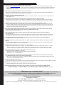
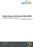
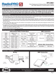
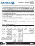
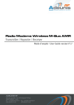
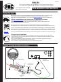
SWI-RC
06-27-13
Universal Steering Wheel Control Interface
Pacific Accessory Corporation
For aftermarket radios equipped
with a wired remote input.
Installation Instructions
Before You Start
Did you know? PAC also produces RadioPRO which is a radio replacement solution, with steering wheel
control retention built-in. This greatly expedites the installation of a new radio into your vehicle.
See if there is a RadioPRO interface for your vehicle, visit www.pac-audio.com and search "Radio PRO"
A. Verify compatibility and get vehicle specific installation instructions.
• Visit www.pac-audio.com/swi for the most current list of compatible vehicles.
Enter your year, make, model, and radio and download time saving, step by step instructions and
wiring information specifically for your vehicle.
Note that some vehicles require the use of an additional CANbus adaptor that is sold separately.
The appropriate part number is indicated in the "CAN" column of the Vehicle Install Information Guide (V.I.I.G.)
If you do not have web access, please take a moment to familiarize yourself with the included printed materials
such as the Vehicle Install Information Guide (V.I.I.G.) which contains many details about the installation in your
vehicle, and the Vehicle Connection Chart (V.C.C.) which has illustrations of the connection point in the vehicle.
Scan with
Smartphone
• Check your aftermarket radios owners manual to ensure it has the proper connections for a wired remote input.
B. Prepare for the installation.
• If possible, install the SWI-RC while you are installing the new head unit. Keep in mind you may need to
plug in the factory stereo to locate certain wires; therefore do not complete the head unit installation until the
SWI-RC is working properly.
• Plan a general installation location for the SWI-RC, keeping in mind that the supplied wire harness is
two feet long, and the 1/8" plug harness is three feet long.
• Use a multimeter or approved measuring device for checking vehicle circuits.
General Overview and Radio Connection
SEEK
PRESET
AM FM
VOLUME
PL AY
MUTE
Steering wheel
audio control wire
12v+
Aftermarket
Radio Connection
LED
Programming
Port for PP-SWI
OR
Programming
Button
Legend: SWC- Steering Wheel Control
V.I.I.G.- Vehicle Install Information Guide V.C.C. - Vehicle Connection Chart
1
Step 1 - Set Radio Select Switch
1. Set the radio select switch on the side of the SWI-RC.
9 01
456
23
Alpine
Blaupunkt
Clarion
Fusion
1
8
4
9
JVC Kenwood
2
3
OEM
Pioneer/Sony/
Other*
Valor
6
7
5
78
*Other = Advent, BOYO, Dual, Lightning Audio, Rockford Fosgate, Visteon
Step 2 -Wiring Information
PLEASE NOTE: Using T-Taps is NOT recommended. It is VERY important that ALL connections be solid & secure.
Soldering or crimp connections are best and will provide reliable operation.
Please visit: www.pac-audio.com/swi for detailed instructions and wiring information for your vehicle.
1. Connect the interface control input wire (white, yellow, orange or green) to the vehicle as indicated in your specific instructions.
2. Connect the BLACK wire to ground (-). For best results use the same ground as the aftermarket radio.
3. Connect the RED wire to switched +12V. This wire should show +12V when the ignition key is turned to the ACC or ON
positions.
4. Cut the necessary loop (Purple or brown) if instructed to do so, in your vehicle specific instructions, or in the printed
Vehicle Install Information Guide (V.I.I.G.)
5. Add the proper resistor(s), if instructed to do so, in your vehicle specific instructions.
Note: some applications, such as Nissan and Harley Davidson, require multiple resistors. We include a pack of resistors with
this product for this purpose. These resistors' colors and values are explained at the bottom of the Troubleshooting section of this
manual. Resistor information can also be found in the "Notes; and install details" column of the V.I.I.G.
Wire resistors according to the "FIG#" diagrams are found in the V.C.C.
Step 3 - Radio Connection
PLEASE NOTE: SWC input may not be located on the radio's chassis. Refer to your radio's manual for connection information.
3.5mm (1/8") plug - Commonly found on chassis of aftermarket radio
Wired connection (Blue/Yellow) - For select Kenwood and JVC radios
Blaupunkt radios with optional wired remote inputs are supported by the SWI-RC, however we do not supply any connectors or
support for Blaupunkt. It is up to the consumer or installer to supply this connector. Use Vehicle Connector Chart and use VW
connector as referenced. Connect the SWI-RC's blue/yel wire to pin #11 of VW connector. The connector you obtain may come
with two or three pieces, however the connector (usually green) should show pin #11 on it.
Step 4 - Programming The Interface
NOTE about programming:
The SWI-RC can be configured for your specific vehicle automatically using the PP-SWI programmer (sold separately). This option
does not require any manual mapping of the SWC button functions. The PP-SWI connects to the port located under the removable
panel on the top of the interface (see illustration on first page).
If you are not using the PP-SWI to automatically configure the SWI-RC, please follow these steps to manually map the SWC button
functions for your vehicle and radio.
Programming The Vehicle Version #
Refer to The Vehicle Install Information Guide or www.pac-audio.com/swi for the proper vehicle version number.
Make a note of it here for quick reference: Vehicle Version # ___________
1. Press and hold programming button on the side of the SWI-RC, and turn the vehicle ignition to the ON position while still
holding the button. The LED on the SWI-RC will turn on. Release the programming button and the LED will turn off.
2. Press and release the programming button the same number of times as the desired vehicle version number.
The LED will flash each time the button is pressed and released.
3. Wait 3 seconds, the LED will flash the same amount of times as the set vehicle version number.
4. Turn vehicle ignition to OFF position. Programming the Vehicle Version Number is complete.
NOTE: If you inadvertently program the wrong version number, simply start again at step #1.
2
Legend: SWC- Steering Wheel Control
V.I.I.G.- Vehicle Install Information Guide V.C.C. - Vehicle Connection Chart
06-27-13
Mapping SWC Button Functions
PLEASE NOTE: If you programmed the SWI-RC for version 4, refer to the section below for the mapping order of the HVAC controls.
These must be mapped BEFORE the other commands listed in the Radio Function Mapping Order chart, below.
The steering wheel control button functions must be mapped in the specific order shown in the chart below. If you come across a function in the
chart that your steering wheel does not have, or you do not want to map, press the Programming Button on the side of the SWI-RC. The LED will
flash twice and then stay on confirming that you have successfully skipped that function and are ready to map the next button function.
1. Start the vehicle. The LED will flash to indicate the set vehicle version number.
2. Press and release programming button on SWI-RC. LED will turn on.
3. Within 7 seconds, press and hold for 5 seconds, the first SWC button to be mapped (volume +). The LED will turn off during this process.
PLEASE NOTE:
If using in conjunction with the OS-4 or MS-FRD1 the Source, Media or Speak buttons cannot be held for more than 1.5 seconds.
4. Release the button. The LED will turn on back on.
5. Repeat steps 3 & 4 for each additional audio function you wish to map to the steering wheel (within 7 seconds).
6. Once you have mapped all the desired button functions, wait 7 seconds. The LED will flash three times indicating end of mapping.
The LED will flash to indicate the set vehicle version number.
7. Test the interface for proper functionality. Whenever an SWC button is pressed the LED on the interface should blink.
If any function does not work, repeat the mapping process or refer to Troubleshooting Guide.
Radio Function Mapping Order
Radio
Alpine
JVC
Kenwood
Clarion
Other*
Sony
Pioneer
Fusion
1
Volume +
Volume +
Volume +
Volume +
Volume +
Volume +
Volume +
Volume +
2
Volume -
Volume -
Volume -
Volume -
Volume -
Volume -
Volume -
Volume -
3
Mute
Mute
Mute
Mute
Mute
Mute
Mute
Mute
4
Preset +
Source
Source
Source
Preset +
Preset +
Preset +
Source
5
Preset -
Track +
Play
Search +
Preset -
Preset -
Preset -
Track +
6
Source
Track -
Track +
Search -
Source
Source
Source
Track -
7
Track +
Band/Disc +
Track -
Band
Track +
Track +
Track +
Audio
8
Track -
Preset/Disc -
Disc/FM +
Send/End
Track -
Track -
Track -
Power
9
Power
Select
Disc/AM -
Send
Band
Band
Band
10
Enter/Play
Attenuation
Answer
11
Band/Program
Phone Receive
Voice Dial
Skip
12
Receive
Phone Reject
On Hook
Skip
End Call
13
End
Voice Dial
Off Hook
Skip
Voice Activation
14
Power
End
Reject Call/Source
Mute
(Multimedia units only)
Phone Menu
(Bluetooth equipped radios only)
Answer Call
Answer/End Call
*Other = Advent, Boyo, Dual, Lightning Audio, Rockford Fosgate, & Visteon
Special Instructions For General Motors Vehicles With Fan / Temp Control Buttons
To Map SWC button functions for GM vehicles with HVAC controls, first program the Vehicle Version # to 4.
HVAC controlls must be mapped BEFORE the other commands listed in the main chart above.
1. Start the vehicle. LED will flash 4 times to indicate the set Vehicle Version #.
2. Press and release programming button on SWI-RC. LED will turn on.
3. Within 7 seconds, press hold for 5 seconds the TEMP UP button on the steering wheel control. LED will turn off and back on.
The function is Mapped.
4. Repeat Step 3, using the TEMP DOWN Button.
5. If the vehicle is equipped with FAN UP and FAN DOWN buttons; Repeat step 3 for these buttons as well.
Once complete the LED will flash two times and stay on.
6. If the vehicle does not have FAN buttons press and release the programming button on the SWI-RC, this will skip those functions and the
LED will flash two times.
7. Within 7 seconds, press and hold for 5 seconds the first SWC button to be mapped. See the R.F.M.O. chart above. (Volume +)
The LED will turn off during this process.
8. Map the rest of the SWC button functions, untill all desired functions are mapped.
9. Release the button. The LED will turn on back on.
10. Once you have mapped all the desired button functions, wait 7 seconds. The LED will flash three times indicating end of mapping.
The LED will flash 4 times to indicate the set vehicle version number(4).
11. Test the interface for proper functionality. Whenever an SWC button is pressed the LED on the interface should blink.
If any function does not work, repeat the mapping process or refer to Troubleshooting Guide.
Legend: SWC- Steering Wheel Control
V.I.I.G.- Vehicle Install Information Guide V.C.C. - Vehicle Connection Chart
3
Troubleshooting Guide
1. My vehicle is not listed in the identification and connection chart.
a) Please visit www.pac-audio.com/swi for the most up to date listing of compatible vehicles. If your specific vehicle is not listed
may not mean that is it not compatible, but may mean we have not tested your vehicle or do not have any information (schematics)
regarding your vehicle. If you are able to obtain specific information regarding your vehicle we may be able to help you to get this
module working in your vehicle.
2. LED flashes when trying to program the vehicle version number.
a) Please ensure that the rotary dial is set to the proper number and not to “0”. Refer to page 2 and select a radio position before
turning on the ignition and attempting to program a version number.
3. No power / will not go into programming mode.
a) Check red wire connection and fuse. Make sure interface is connected to switched +12 volts, not constant +12 volts. Make sure
vehicle ignition is on.
4. The Interface controls the stereo immediately without pressing any buttons on the steering wheel.
a) During mapping, press the buttons on the steering wheel FIRMLY for 5 seconds. Releasing the button too early will cause the
Interface to send out a signal even when no buttons are pressed. Also ensure that the brown loop is not cut unless instructed.
5. The radio changes tracks when the vehicle is turned off or does not work when the car/truck is running.
a) Wire a relay to provide power. Pin 86 of the relay will connect to the radio’s remote (Blue/White) wire. Pin 85 of the relay will
connect to chassis ground. Pin 30 of the relay will need to connect to the vehicle’s constant 12v circuit. Pin 87 of the relay will
need to connect to the red wire on the SWI interface. A standard 5 pin automotive relay (Single Pole Double Throw) should be
used and can be found at most automotive parts stores.
6. I am using an Axxess radio replacement interface and I have programmed the vehicle version number, when I put the
module into mapping mode to map the vehicle buttons the LED just flashes steady.
a) Wire in relay as described in #5 (above)
7. When mapping the SWC button functions, it takes 5 seconds for the light to go out and it never comes back on,
or it never turns off.
a) Do the connection instructions say to connect another vehicle wire to accessory power or chassis ground? If so, test the circuit
with a Digital Multi-Meter (the factory radio must be plugged in) and verify that the factory radio is providing the same output
8. The Interface controls the radio whenever the steering wheel is turned (mostly late 80’s early 90’s Honda/Acura)
a) Program the interface for vehicle version #12.
9. The module is put into programming mode and once I press the Volume up button the LED turns off and does not come
back on.
a) This is normally an indication of a connection issue to the vehicle wiring. Double check the wiring with a digital multimeter to
ensure the proper voltages are seen on the interface wires.
10. What are the rest of these wires on the interface’s 11 pin connector?
a) Green wire – (Used in versions 1, 2, 4 and 10) - 12v resistive systems normally found in GM vehicles. White wire – (Used in
versions 3, 8, 9 and 11) - 5v resistive systems normally found in Domestic and Japanese vehicles. Yellow Wire – (used in
version 5) Serial Data. Orange Wire – (used in version 6 and 7) Serial Data. Blue wire – (used in version 4) Data Output.
11. My module’s LED is flashing but it is not controlling the aftermarket radio.
a) Check the perspective output with a multi meter.
Dial Setting 1,2,3,4 = DC voltage pulses on BLU/YEL wire (this is serial data).
Dial setting 5,6,7,8,9 = Variable resistance.
12. I am using a radio replacement Interface, an OS-4 or C2R module, and the instructions for the vehicle version number
are different from what is shown in the vehicle application guide.
a) When using a radio replacement interface you will want to follow the instructions for the radio replacement interface and not the
ones found in the vehicle application guide.
13. Only some SWC buttons are working.
a) Verify wiring instructions and configuration. Some vehicles have multiple SWC wires, and sometimes require the addition of resistors.
14. Buttons do not work when car is running, only when car is not running.
a) Perform "Mapping SWC button functions" in Step 4, but with the vehicle running.
15. Resistor Pack Definitions. These are the colors and values of resistors are provided with your SWI-RC module.
47 Ohm = Yel, Vio, Blk. 100 Ohm = Brn, Blk, Brn. 150 Ohm = Brn, Grn, Brn. 560 Ohm = Grn, Blu, Brn.
1000 Ohm = Brn, Blk, Red. 1500 Ohm = Brn, Grn, Red. 3900 Ohm = Org, Wht, Red. 5100 Ohm = Grn, Brn, Red.
Working on a new or unlisted vehicle?
We are always looking for new vehicle information. If you’ve successfully completed the installation on a vehicle with
steering wheel controls, and the vehicle is not listed in these instructions or on our Website, contact us at
[email protected] so that we may add the information to the instructions.
Pacific Accessory Corporation
Santa Ana, CA 92705
[email protected] • www.pac-audio.com
Copyright 2013 Pacific Accessory Corporation. Content subject to change without notice.
4
Legend: SWC- Steering Wheel Control
V.I.I.G.- Vehicle Install Information Guide V.C.C. - Vehicle Connection Chart