1
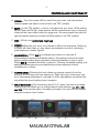
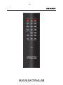
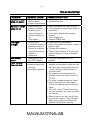
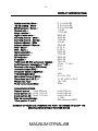
Magnum Dynalab MD 107T/107TR
ANALOG FM TUNER
INSTRUCTION MANUAL
-2-
TABLE OF CONTENTS
A MESSAGE FROM THE PRESIDENT
3
UNPACKING YOUR 107T
4
SETTING UP YOUR MD 107T
5
CONTROLS AND FUNCTIONALITY
6
DISPLAYS AND METERS
7
CHECKING OUT YOUR MD 107T
8
TUNER REMOTE (OPTIONAL)
9
RC6 REMOTE IMAGE
10
TROUBLESHOOTING
11
RECEPTION TECHNIQUES
12
Antenna Cabling:
12
Types of Antennas:
12
FM RECEPTION AIDS AND ACCESSORIES
13
PRODUCT SPECIFICATIONS
14
SAFETY SHEET
15
LIMITED WARRANTY
16
-3-
A Message From the President
Thank you for choosing the Magnum Dynalab “MD 107T” FM Tuner. Great care
has been given in the design, manufacturing and selection of components for the
“MD 107T” FM Tuner. This complete process will insure that your listening
experience will be optimized for years.
The front end of all Magnum Dynalab tuners is an exclusive “in house” designed
and manufactured component, we are the only company in the world that does
their own R.F. “Front-end”. The reason that we design and build our own front-end
is that no other manufacturer can make one that meets our exacting
specifications. The importance of a front-end to the tuner is the equivalent of a
high performance laser mechanism to a CD transport. The front-end must gather
the FM signal and isolate it from the extraneous aberrations inherent in the
environment as well as the FM stations adjacent to it. Our rigid criteria for our
tuners and their front-ends insure that you get the most out of your FM reception
with the highest degree of consistency available in the industry.
To insure that all specifications on our tuners are met at ALL frequencies, we
manually align our tuners front-end at three frequencies (92 MHz, 101.5 MHz
and 106MHz). This process optimizes tuning performance across the entire FM
band, so that you attain the same levels of quality regardless of where you are
tuned.
These procedures also ensure that the balance between SENSITIVITY,
SELECTIVITY and MUSICALITY are maintained. Your tuner is now optimized to
reject strong adjacent channel noise, provide more consistent levels of tuning
performance across FM band and to have a superior ability to isolate the station
you wish to listen to from the extraneous interference of the FM signals.
Once again MAGNUM DYNALAB thanks you for including our product in your
audio system, we are sure that you will have years of listening pleasure from your
“MD 107T”. If there is anything else we can offer to aid your enjoyment in
listening to FM, please feel free to contact us on our toll free number, 1-800551-4130 or via email at: [email protected].
Respectfully yours,
Larry Zurowski
President
-4-
UNPACKING YOUR 107T
Carefully inspect all sides of the shipping carton for damage. If there are marks or
holes in the carton make note of the location in relation to the unit inside. Any
obvious dents or scuff marks should alert you to the possibility of damage.
Carefully remove the MD 107T from the end caps and wrapping, inspect all
sides. Pay special attention to the corresponding areas on the unit where damage
was found to the shipping carton. If damage is evident, document the type and
extent of the damage, then repack the unit and call the dealer.
KINDLY DO NOT SEND THE UNIT BACK TO THE SHIPPER UNTIL YOU HAVE BEEN
ASKED TO DO SO.
DO NOT DISCARD THE PACKING MATERIALS AND CARTONS. Should there be a
necessity to return the unit for any reason, it must arrive safely and suitably
packaged in order for our receiver to accept it from the carrier. Also, if the unit
has incurred damage as a result of improper packaging, it is not likely that a
claim for the damage against the carrier will be successful.
Likewise, we will ship your unit back to you only in factory-approved packaging,
however, if the unit were to arrive at the factory in anything other than factory
approved packaging, we reserve the right to return the product in factoryapproved packaging and charge the cost of the packaging to the shipper. This is
the only way we can assure your unit of a safe return (damage by carrier
excepted).
-5-
SETTING UP YOUR MD 107T
1. Place your tuner the shortest distance possible from your pre-amplifier/
integrated amplifier, being careful to avoid areas that may cause extreme
temperatures.
2. Connect your tuner to the pre-amplifier, using cables/ inter-connects that are
consistent with the rest of the inter-connects in your system. For a single ended
(un-balanced) system the cables will be connected to the RCA connectors labeled
“output to preamp” on the rear panel of your tuner to an unused aux. input on the
rear of your pre-amplifier/ integrated amplifier. For connection to a balanced
system, the balanced cables will be connected from the XLR outputs marked
“output balanced” on the rear of your tuner to the balanced inputs on the rear of
your pre-amplifier/ integrated amplifier.
3. Connect your FM antenna cable to the ANTENNA IN terminal on the rear
panel of your tuner. The connection type on the back of your tuner is an “F”
connector (75 ohms). Should your antenna cable be 300 twin lead, you may
convert this to 75 ohms with a 300 ohm to 75 ohm balun/ transformer.
4. Make sure that the center conductor of the cable is properly inserted into the
connector. If you do not possess an antenna, attach the temporary wire
(enclosed in box) to your tuner. Place this into the “F” connector input on the rear
of your tuner.
5. If you have the D.A.C. option, connect the digital inter-connect to either the
“D1”, “D2”, OR “D3” input.
6. Unwrap the EIA AC cord and plug the EIA end into the rear socket marked
“Power Input” on the rear panel of your tuner. Plug the other end of the AC cord
into a 120/220/230/240 volt continuous AC source that you are using.
Please note that the piece of wire provided as an antenna should only be used as
a medium to test and setup the tuner. A better antenna system is
recommended. Magnum Dynalab offers a number of different antennae, these
antennae are discussed in the Reception Techniques in the back of the manual.
Note: Many countries that use 220/230/240 volts have a special FM
transmitter; tuning de-emphasis for these countries may be different. Please
consult Magnum Dynalab for the correct usage. If your tuner is used in a country
where the tuning de-emphasis is set incorrectly the sonic performance will be
seriously affected.
-6-
CONTROLS AND FUNCTIONALITY
A. POWER – Turns the power (AC) on and off to your tuner, with the optional
remote system this switch must be left in the “OFF” position.
B. MUTE – In the “ON” position, a limit is now placed on your tuner. While scaling
up and down the FM dial, weak stations will be overlooked so that no alarming
noises will be heard while looking for programs. We recommend that with the
optional remote system you leave the Mute switch in the “ON” position.
C. DIM – Will dim the centre tune magic eye
D. STEREO – Switches
your tuner from Stereo to Mono and vice-versa. FSwitching
A
to Mono will often clean up noisy stereo transmissions and aid in delivering
quiet listening to weaker signals.
B
C
D
E
E. BANDWIDTH – When BW 1 is selected your tuner is in the wide IF
(Intermediate Frequency) bandwidth setting. This setting produces the best
sound possible where strong adjacent channel interference is not an issue.
When BW 2 is selected the tuner is placed in “Narrow” bandwidth setting, this
setting produces optimal sound performance where adjacent channel
interference is a factor.
F. TUNING KNOB – Rotating this knob allows you precise control of the fine
tuning of the FM signal you are listening to. Slight de-tuning of the tuner may
aid in eliminating measures of multi-path or other atmospheric conditions that
may affect the sound quality of your reception.
G. INPUT SELECTOR – Only functioning when D.A.C. option has been purchased,
rotating this knob allows you to change desired input between ‘tu’, ‘D1’, ‘D2’,
and ‘D3’. If the remote option has been purchased, the input can be changed
using the remotes ‘input’ button.
-7-
DISPLAYS AND METERS
H. SIGNAL STENGTH– This meter readout indicates the amount of signal the
tuner is receiving, the higher the better. This will never read “100”.
I. MULTI-PATH/SIGNAL METER - This meter indicates the amount of multi-path,
the lower the reading the better.
J. FREQUENCY/INPUT DISPLAY – Displays the station via a numeric value, the
frequency that your tuner is dialed into. Display ranges from 87.5 MHz
through 108.5 MHz. This readout is controlled by the tuning knob (F on
diagram)
CENTER TUNE MAGIC EYE – Indicates the setting of the tuners front end in
relation to the station you are tuning to. To insure that the tuner is tuned to its
optimum position, the dark green part of the eye should be at its max, or
closed.
-8-
CHECKING OUT YOUR MD 107T
1. Place your power switch to the “ON” position (A on diagram). This should turn
on your tuner’s meter lights and frequency display.
2. Place your STEREO/MONO switch (D on diagram) to the Stereo setting.
3. Place your bandwidth switch (E on diagram) to BW1.
4. Place your Mute switch (B on diagram) to “ON” position.
5. On your preamplifier/ integrated amplifier select the input that your MD 107T
tuner is connected to.
6. Rotate the tuning knob on your tuner (F on diagram), or adjust frequency using
the remote until sound is heard through your speakers, now fine tune this
station using the Magic Eye (I on diagram) and signal strength meter (H on
diagram) as indicators. Your stereo light on the face of your tuner should be
on. Place the stereo/mono switch (D on diagram) to the Mono position, your
stereo light should now go off. Now turn the stereo/mono switch back to the
Stereo position and your Stereo indicator light should turn back on.
7. You are ready now to search through FM frequencies in search of your
favorite stations. If you encounter difficult reception situations please read the
Controls and Functionality section of your manual.
8. Approximately 48 hours of “burn in” should eliminate any measure of drifting
that you may encounter with your new tuner. Please note that when your tuner
is turned off for more than a couple of hours, upon powering “ON” your tuner,
you may encounter a slight amount of drift on the station you were last tuned
to. Please do not touch the dial, as when the tuner warms back up, it will
return to where it was last center tuned.
-9-
TUNER REMOTE (OPTIONAL)
If your tuner was ordered with the RC6 “PRECISION REMOTE SYSTEM”, here are
the operating instructions.
1. The power switch should be off on the front panel of the tuner
2. Using the remote handheld, push the red “TUNER” button. You will see the
tuner turn on.
3. To tune with the handheld, push and then hold either the “TUNE UP” or
“TUNE DOWN” button until you reach the desired station. The longer you
hold the button the faster the frequency changes. To FINE TUNE hold either
button for a shorter time, or tap until your magic eye tube is closed.
4. Your Precision remote gives you the ability to store and scan up to 20
preset stations. To program a preset station, first tune to the desired
station and then push “STORE”. Then select the preset memory position you
want to store this station in by selecting two digits. For numbers 1-9 you
must select 01-09 and for 10+ directly enter the number.
*NOTE-When setting a preset you must enter the numbers quickly and tap, do
not hold down, the buttons as they are very sensitive.
* Once presets have been entered, briefly turn off the unit with the remote to
save changes
5. To recall a preset, you can push the preset button and the number of the
preset you want.
6. To reset or purge the presets press “p” then “s” within 5 seconds.
7. To turn your tuner off, push the “TUNER OFF” button until you see the tuner
turn off.
** If you have purchased the optional DAC upgrade to the MD 107T, you may
switch between inputs using the left knob or your remote.
Press the “input” button then number:
6 for D1 - RCA
7 for D2 – Optical
8 for USB
9 for Tuner
Your RC6 remote operates with 2 AA batteries, which are included.
- 10 -
RC6 REMOTE
- 11 -
TROUBLESHOOTING
PROBLEM
POSSIBLE CAUSE
No sound, meter • Power cord
lights are not on
disconnected
• Power off at source
No sound, meter • Interconnect not
lights are on
properly installed
• Preamp set to
incorrect source
• Power amplifier is
off
• Tube failure
Low signal
• Antenna not
strength
connected properly
• Incorrect antenna
Station too distant
• Improper antenna
position/
placement
Intermittent
• Mute switch is in
sound
the “ON” position
Tuner remote
• Batteries dead
does not work
• Buttons being held
too long
• Improper sequence
POSSIBLE SOLUTION
• Connect power cord
• Check AC source
• Verify installation of interconnects
• Turn preamp to input where tuner is
connected
• On preamp defeat tape monitor
function
• Turn amplifier on
• Replace 6922 tube
• Check antenna connection
Check instruction manual for correct
antenna type
• Change your antenna
• Rotate your antenna or mount your
antenna higher or near a window if
indoors
• Turn the mute switch to “OFF”
position
• Power switch should be in the off
position on standard tuners and the
remote must be activated with the
“Tuner Remote” power button on
the hand held.
• All stations must be stored and
recalled with a two digit code from
01-20.
• To store a preset press the “store”
button then the two digit preset.
Touch the buttons very quickly and
lightly.
• To recall, touch “Preset” and then
the two numbers you want to recall
very quickly.
• Make sure to turn the unit off with
the remote control “Tuner Remote”
after storing as this will save the
stations to the flash memory.
- 12 No sound from
USB
• Not compatible
• Signal not receiving
• Restart your computer or program
• If using a MAC, you must go to
“system preferences”, “sound” and
select “USB DAC”
RECEPTION TECHNIQUES
Antenna Cabling:
The lead-in cable from the antenna is often the weakest link in the FM system.
Some time spent on selection and matching will yield dramatic results when it
comes to noise reduction in weak signals.
A good grade of 75 ohm coaxial cable will provide very sufficient signal passage,
along with effective shielding against interference. Without effective shielding your
coaxial cable can in fact become an antenna in itself. There are different grades
of 75 ohm cable, there is RG59/U (Suitable for 50 feet and less) and RG 6. RG
6 is the better of the two and should be used in runs of 50 feet or more. The RG
6 has quad shielding and 50 % less losses than RG 59/U.
The key to maximizing the efficiency of the system is insuring that all connections
are clean and tight, silicon grease on outdoor connections will insure good
performance over a long period of time. If you splice either cable, make sure that
exactly the same type of cable is used.
Types of Antennas:
Multi-element Yagi - This is a unidirectional antenna capable of pulling in very
distant stations due to its high gain, the higher the gain the better. These types of
antennas are very directional and should be used with a rotor to get the
maximum benefit of the antenna. The directional feature helps eliminate multi-path
problems by allowing only the signal from the direction that the antenna is facing
to be picked up by the antenna and not the signals that come from a different
direction.
Magnum Dynalab offers two Yagi antennae, the MD 6 FM or MD 10 FM
Vertical ½ Wave - This design offers ease of installation and operation. This type
of antenna is omni-directional, which means that it picks up stations coming from
all directions. No rotor is required to pull in stations from behind or the side. This
design also gathers more of the FM signal from the air, offering superior fidelity
over that of a standard bi-directional antenna. It also gives 2.5 dB gain to the
signal strength over that of a standard dipole.
- 13 -
If multi-path is a reception problem try laying the antenna down in the horizontal
plane rather than the vertical plane. This type of antenna can be used indoors or
outdoors, but regardless of whether it is installed indoors or outdoors the higher
that you can put it the better it will perform.
Magnum Dynalab offers the MD ST-2, an excellent vertical ½ wave antenna
Folded Di-Pole - This is the most common and simplest of all antennas, most
people are familiar with the 79 cent piece of wire you received with most
electronics gear (generally provided with a tuner or receiver). This piece of wire is
bi-directional and the performance of it is affected by the angle that the signal hits
the piece of wire. There are quite a number of di-pole antenna designs; they work
well in areas of strong signal strength, such as local stations.
Magnum Dynalab offers the SR-100 as a good folded di-pole.
There are many styles of antennas but all of them are based on one of these
types.
FM RECEPTION AIDS AND ACCESSORIES
We have already alluded to the importance of a good quality antenna which has
been designed and built with the reception of the FM bandwidth exclusively.
SHOULD YOU ENCOUNTER A SITUATION IN WHICH YOU REQUIRE MORE GAIN
TO THE FM SIGNAL OR SITUATIONS WHERE YOU MAY NEED LESS GAIN AND
BETTER SELECTIVITY THEN THE MAGNUM DYNALAB 205 “SIGNAL SLEUTH”
MAY BE OF BENEFIT TO YOU.
THE 205 IS A FM SIGNAL PROCESSOR/AMPLIFIER DESIGNED SPECIFICALLY FOR
FM. IF YOU WOULD LIKE MORE INFORMATION ON THIS ITEM, PLEASE FEEL
FREE TO CONTACT US AT ANY TIME. CALL US TOLL FREE 1-800-551-4130,
EMAIL US AT [email protected] OR VISIT US AT
WWW.MAGNUMDYNALAB.COM.
- 14 -
PRODUCT SPECIFICATIONS
Usable sensitivity- Mono –
50 dB quieting – Mono –
50 dB quieting – Stereo –
Capture ratio –
Image rejection –
Signal to noise ratio –
Alternate channel – Wide –
Alternate channel – Narrow Adjacent channel – Wide –
Adjacent channel – Narrow THD – Mono –
THD – Stereo –
Stereo separation –
AM suppression –
SCA rejection –
IF rejection –
19 KHz and 38 KHz component rejection –
Audio frequency response (+/- 1 dB) –
Balanced audio output (600 ohms)
Line audio output (RCA) –
Line power (Must be specified) –
110/220/230/240Dimensions (inches H.W.D.) –
Dimensions (cm H.W.D.) –
Weight (lbs./kgs) Power consumption (Max) TUBE SPECIFICATIONS
Filament current
(max) 330 mA
Anode current (1) (max) 1.07 mA
Anode current (2) (max) 1.07 mA
Total harmonic distortion
Tubes position 1 and 2
0.7 uV 9.0 dBf
2.0 uV 9.9 dBf
2.3 uV 25.0 dBf
1.5 dB
110.0 dB
80.0 dB
40.0 dB
70.0 dB
3.0 dB
35.0 dB
0.10 %
0.18 %
50.0 dB
70.0 dB
80.0 dB
80.0 dB
75.0 dB
15 Hz – 17 KHz
2.2 V
1.0 V
VAC
4 x 19 x 13.5
11.43 x 48.3 x 34.3
18/7.96
50w
(min) 270 mA
(min) 0.92 mA
(min) 0.92 mA
< 1.8%
MD Reference 6922
MAGNUM DYNALAB LTD. RESERVES THE RIGHT TO CHANGE OR MODIFY THE
SPECIFICATIONS WITHOUT FURTHER NOTICE
- 15 -
SAFETY SHEET
IMPORTANT SAFETY INSTRUCTIONS
1.
2.
3.
4.
5.
6.
7.
8.
9.
10.
11.
12.
13.
14.
KEEP THESE INSTRUCTIONS
HEED ALL WARNINGS
FOLLOW ALL INSTRUCTIONS
DO NOT USE THIS APPARATUS IN WATER
CLEAN ONLY WITH DRY CLOTH
DO NOT BLOCK ANY VENTILATION OPENINGS, INSTALL IN ACCORDANCE
WITH THE MANUFACTURER’S INSTRUCTIONS.
DO NOT INSTALL NEAR ANY HEAT SOURCES SUCH AS RADIATORS, HEAT
REGISTERS, STOVES, OR OTHER APPARATUS (INCLUDING AMPLIFIERS)
THAT PRODUCE HEAT.
DO NOT DEFEAT THE SAFETY PURPOSE OF THE GROUNDING TYPE PLUG.
THE GROUNDING PLUG HAS TWO BLADES AND A THIRD GROUNDING
PRONG. THE THIRD PRONG IS PROVIDED FOR YOUR SAFETY. IF THE
PROVIDED PLUG DOES NOT FIT INTO YOUR OUTLET, CONSULT AN
ELECTRICIAN FOR REPLACEMENT OF THE OBSOLETE OUTLET.
PROTECT THE POWER CORD FROM BEING WALKED ON OR PINCHED
PARTICULARLY AT PLUGS, CONVENIENCE RECEPTACLES, AND THE POINT
WHERE THEY EXIT FROM THE APPARATUS.
ONLY USE ATTACHMENTS/ACCESSORIES SPECIFIED BY THE
MANUFACTURER.
UNPLUG THIS APPARATUS DURING LIGHTNING STORMS OR WHEN
UNUSED FOR LONG PERIODS OF TIME.
REFER ALL SERVICING TO QUALIFIED PERSONNEL. SERVICING IS
REQUIRED WHEN THE APPARATUS HAS BEEN DAMAGED IN ANY WAY,
SUCH AS THE POWER SUPPLY CORD OR PLUG IS DAMAGED, LIQUID HAS
BEEN SPILLED OR OBJECTS HAVE FALLEN INTO THE APPARATUS, THE
APPARATUS HAS BEEN EXPOSED TO RAIN OR MOISTURE, DOES NOT
OPERATE NORMALLY, OR HAS BEEN DROPPED.
THE EQUIPMENT REQUIRES A GROUNDED POWER OUTLET TO OPERATE
SAFELY.
THE POWER SUPPLY CORD IS THE MAIN DISCONNECT AND SHALL BE
READILY OPERABLE.
“WARNING” TO REDUCE THE RISK OF FIRE OR ELECTRIC SHOCK, DO
NOT EXPOSE THIS APPARATUS TO RAIN OR MOISTURE.
- 16 -
LIMITED WARRANTY
Register your product at www.magnumdynalab.com
Magnum Dynalab Ltd. herein referred to as the “manufacturer” guarantees
this product to be free of defect in both material and workmanship and agrees to
remedy any such defect or replace any defective component at no charge for a
period of two years from date of sale to the first end user. This warranty is void if
the product has been found to be subjected to misuse, abuse, lightning strike,
unauthorized service, damaged in transit or has been altered or repaired in such
a way as to detract from its performance, reliability or its safe operation. All
tubes are covered for 12 months.
Should such defect be discovered and it falls within the terms of this
guarantee, the manufacturer will correct the defect in workmanship and/or
replace any defective component with a new one of similar capability and value.
This warranty does not apply to the cabinet or appearance items such as the
faceplate, control knobs or meter lenses nor does it cover any expenses in
shipping the unit to the appropriate service depot.
The foregoing is in lieu of any other warranties expressed, implied or
statutory and the manufacturer neither assumes nor authorizes any person to
assume for it any other obligation or liability in the connection with the sale of this
product. This warranty is not transferable except by written authorization from
the manufacturer.
In order to qualify under the terms of the above warranty, all items must be
returned to the appropriate factory service depot with all shipping charges
prepaid in lieu of having previously registered the purchase of the unit by
completing and returning the attached Registration Card, the unit must be
accompanied by proof from an authorized Magnum Dynalab Ltd. dealer.
YOUR LOCATION
Within the USA
Within Canada
Other Countries
RETURN SHIPPING ADDRESS
Please contact us at
[email protected] or
PHONE: 1-800-551-4130
Magnum Dynalab Ltd.
8 Strathearn Avenue, Unit # 9
Brampton, ON, Canada
L6T 4L9
PHONE: 1-800-551-4130
Contact selling dealer
TO PREVENT FIRE SHOCK OR HAZARD, DO NOT EXPOSE THIS APPLIANCE TO
RAIN OR MOISTURE. TO REDUCE THE RISK OF ELECTRIC SHOCK, DO NOT
REMOVE COVER OR FACEPLATE, NO USER SERVICEABLE PARTS INSIDE. REFER
SERVICING TO QUALIFIED SERVICE PERSONNEL.