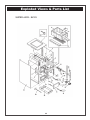
1
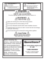
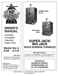
SUPER JACK
MODEL SJ125
OWNER’S
MANUAL
ASSEMBLY
INSTALLATION
OPERATION
REPAIR PARTS
BIG JACK
MODEL BJ90
MODEL NUMBERS
BJ90 AND SJ125
CANADIAN MODELS
BJ90-C AND SJ125-C
SUPER JACK & BIG JACK
WOOD BURNING FURNACES
CAUTION:
Read Rules and Instructions
Carefully for Safe Operation
IMPORTANT:
Installation must be made in
accordance with State and
Local Ordinances which may
differ from this Installation
Manual.
ALPHA AMERICAN CO., 10 INDUSTRIAL BLVD., PALISADE, MN 56469
www.yukon-eagle.com
FOR YOUR SAFETY:
FOR YOUR SAFETY:
If you smell gas:
1. Open windows
2. Do not touch electrical switches
3. Extinguish any open flame
4. Immediately call your gas supplier
Do not store or use gasoline or
other flammable vapors and
liquids in the vicinity of this or
any other appliance.
DANGER
RISK OF FIRE OR EXPLOSION
Do not burn garbage, gasoline, drain oil, kerosene, thinners, etc.
WARNING
RISK OF FIRE
Tightly close the firing door and ash door during operation.
Do not operate with flue draft exceeding .03" W.C.
Do not store flammable materials within marked installation clearance.
Frequently inspect and clean soot and/or creosote from the heat exchanger,
smoke pipe, and chimney.
Do not connect this unit to a chimney flue serving another appliance.
CAUTION
BLACK SURFACES ARE HOT
Keep children away. Do not touch.
Before installing this
furnace, read and follow all
instructions in this manual.
It is recommended that a
heating professional installs
or supervises the entire
installation of the furnace,
ducts, chimney and
electrical connections.
Questions?
Visit www.yukon-eagle.com
or call
1-800-358-0060
For repair or replacement parts,
See back cover for details.
2
TABLE OF CONTENTS
INTRODUCTION
Safety Statements.......................................................................................................................2, 4-6
Unpacking and Inspection.................................................................................................................7
Features and Benefits of SJ125.....................................................................................................8, 9
Features and Benefits of BJ90.................................................................................................. 10, 11
BJ90 Specifications .......................................................................................................................12
SJ125 Specifications ......................................................................................................................13
PLAN YOUR INSTALLATION
Plan your Installation .....................................................................................................................14
Locating the Furnace .....................................................................................................................15
Clearances to Combustibles ..........................................................................................................15
Typical Installations ......................................................................................................................16
Proper Chimneys ...........................................................................................................................17
Furnace Located in Confined Space .............................................................................................18
Combustion Air (Make Up Air) ....................................................................................................19
INSTALLATION
Place Furnace ...............................................................................................................................20
Furnace Casing .........................................................................................................................20-21
Combustion Blower .......................................................................................................................22
Junction Box .................................................................................................................................22
Fan and Limit Control ..................................................................................................................23
Mounting Thermostat .....................................................................................................................24
Electrical Wiring ............................................................................................................................25
Wiring Diagram ......................................................................................................................26, 27
Connecting Smoke Pipe ...............................................................................................................28
Barometric Draft Regulator .....................................................................................................29-31
OPERATING FURNACE
Best Wood to Burn ......................................................................................................................32
Helpful Hints ................................................................................................................................33
Wood Firing the Furnace ...............................................................................................................34
Burning Coal ..........................................................................................................................35, 36
Ash Removal ................................................................................................................................37
MAINTENANCE
Faulty Chimney and Draft Problems ......................................................................................38, 39
Cleaning Chimney, Smoke Pipe and Heat Exchanger ................................................................40
EXPLODED VIEWS AND PARTS LISTS
Super Jack (SJ125) .................................................................................................................42, 43
Big Jack (BJ90) ......................................................................................................................44, 45
SERVICE HINTS & TROUBLESHOOTING.....................................................................46, 47
YOUR NOTES..........................................................................................................................48-51
3
Safety Statements
SAVE THESE INSTRUCTIONS
STOP FOR SAFETY!
Safe assembly, operating and maintenance practices should always be
followed whenever using any equipment. Wherever you see the caution sign,
extra safety precautions should be taken.
You must stop, read, and carefully follow the safety instructions before proceeding.
READ THROUGH THE ENTIRE MANUAL
It is recommended to read through the entire manual before beginning your
installation and/or operating your furnace. Follow all steps exactly.
NFPA PRACTICES
Areas of this manual refer to the National Fire Protection
Association (NFPA). NFPA is a non-profit organization.
This furnace must be installed according to NFPA codes.
NFPA Codes, Standards, recommended practices, and guides referred to in this document are approved by
the American National Standards Institute. State and local codes are adopted from these standards.
DANGERS-CAUTION - FIRE HAZARDS
(BURN WOOD LOGS OR COAL ONLY)
Ducts and Plenums shall be constructed entirely of sheet metal
Do Not use flammable liquids to start a fire.
Do Not attempt to light a wood fire when gas or oil vapors are present.
Do Not install on a combustible floor.
In the event of an electrical power failure, be sure ash door and fire door remain closed.
Do Not install a power humidifier on warm air plenum.
Store all ashes in a metal container with a tight fitting lid. Allow ashes to cool before disposing of them.
Be sure there is a sufficient supply of outside combustion air to the area where the furnace is located.
Keep smoke pipe connection as short as possible with a minimum of 1-inch rise per linear foot from the
furnace to the chimney opening. Smoke pipe shall be 24 gauge galvanized or black pipe.
Before servicing, allow furnace to cool. Shut off electricity.
Familiarize yourself with this wood burning furnace before leaving it unattended.
Follow a regular service and maintenance schedule of furnace and chimney.
IN THE EVENT OF A CHIMNEY FIRE, CALL FIRE DEPARTMENT, AND THEN BE SURE ALL FURNACE
DOORS ARE CLOSED TIGHTLY. TURN OFF ELECTRIC POWER TO FURNACE.
4
Safety Statements
CAUTION
INSPECT FLUE PIPES, FLUE PIPE JOINTS, AND FLUE PIPE SEALS REGULARLY TO ENSURE
THAT SMOKE AND FLUE GASES ARE NOT DRAWN INTO, AND CIRCULATED BY, THE AIRCIRCULATION SYSTEM.
CAUTION
THE WARM-AIR SUPPLY OF THE SUPPLEMENTARY FURNACE SHALL NOT BE CONNECTED
TO THE COLD-AIR RETURN DUCTING OF THE CENTRAL FURNACE.
Installation shall comply with CAN/CSA-B365 and if changes are made to the central furnace, changes are to comply with CSA-B139 (add-on to oil furnaces), CSA C22.1 (add-on
to electric furnaces), or CAN/CGA-B149.1 or B149.2 (add-on to gas furnaces).
ADD-ON to GAS FURNACE INSTALLATIONS
When adding on to a gas furnace, the operation of the gas furnace must be verified
for acceptable operation before and after installation of the Jack add-on furnace by a
gas fitter who is recognized by the regulatory authority.
DO NOT connect, under any circumstances, to the chimney or vent serving a gas
furnace or gas appliance.
Operate the gas-fired unit periodically to ensure that it will operate satisfactorily
when needed.
DO NOT relocate or bypass any of the safety controls in the original furnace installation.
DO NOT use duct elbows having an inside radius of less than 150 mm (6 in)
Unit shall only be installed on a furnace duct system and chimney that are in good
operating condition.
External static pressure of the central furnace shall be measured before any changes are made for the Jack add-on installation. These values shall be maintained following the add-on installation.
Questions? Visit www.yukon-eagle.com or call 1-800-358-0060
5
Safety Statements
TO THE INSTALLER
It is necessary to ensure that there is sufficient air flow through each furnace after the addon installation has been completed. It is suggested that the temperature rise method be
used since most installers are likely to have the necessary equipment. The temperature
measurements may be made using a potentiometer and thermocouples, mercury thermometers. If thermometers are used, sufficient time must be allowed for the thermometer to reach
actual temperature. As much as twenty minutes may be required.
PROCEDURE
To check the existing system, drill a hole 1/4” in the side of the return plenum on the primary
furnace and a similar 1/4” hole in the side of the main supply air duct, 24” from the supply air
plenum. Insert a temperature measuring device in each of these holes and start the primary
furnace. Allow the furnace to operate until all temperatures have stabilized. This will take at
least 1/2 an hour. Read the two temperatures thus obtained and not the difference, TS - TR.
(see diagram 1, page 16). This difference should not exceed 85 degrees F. (29° C)
Complete the installation of the Jack as an add-on furnace and drill a third 1/4” hole in the
TA (See TA, page 16). Insert a temperature measuring device.
Operate the primary furnace until the temperature rise TA - TR across the primary furnace is
equal to or less than 85 degrees F (29° C). Should this temperature difference exceed 85
degrees (29° C), increase the blower speed until the temperature rise TA - TR is equal or
less than 85 degrees F (29° C).
Shut off the primary furnace and build a fire in the Jack unit. When the fire is established, fill
the fire box to the top of the firebrick (maximum level). Open the combustion blower air
damper. Allow the temperature to stabilize and measure the temperature difference TS - TR.
Should it exceed 85 degree F (29° C), a further increase in blower speed will be necessary.
Once the proper air temperature rise has been obtained, an ammeter should be connected
to the blower motor to measure current draw. If it exceeds the name plate rating, change the
motor to a higher rating (if the old motor was a two stage, ensure that the new motor is as
well). It is permissible to change the blower motor and blower drive pulleys in the primary
furnace but not the blower unit.
This equipment must be installed according to the manufacturer’s instructions and in a manner acceptable to the regulatory authority having jurisdiction by mechanics experienced in
such a service. When required by regulatory authority, such mechanics shall be licensed to
perform this service.
6
Unpack and Check your Cartons
INSPECT SHIPMENT
Note any damage to the shipping cartons. Remove all
items from your shipping cartons. Check all items
against the packing list below. Note any items lost or
damaged in shipment. Refer to the exploded view and
parts list in the back of the manual for the part names
and numbers of missing or damaged items. Keep the
small parts in the parts bag until you are ready to
install them.
Inspect the furnace for visible damage.
The furnace is shipped strapped to a pallet.
Inside the wood loading door is another carton.
This carton contains:
·
·
·
·
·
·
·
·
·
·
·
Barometric Draft Regulator
Gasket
Conduit Clip
Wiring Harness
Fan and Limit control
Combustion Blower
Transformer-Relay
Interlock Relay
Thermostat
Owner’s Manual
Warranty Sheet
- SJ125
Super Jack
Note:
If ordered, the Circulating Blower and Motor and
Cabinet are shipped in separate cartons.
Plenum Packages are also shipped in a separate
carton.
Big Jack - BJ90
7
Furnace Features - SJ125
1
FAN AND LIMIT CONTROL
The fan limit control turns the fan on
and off. It works off of temperature
and also provides a high temperature
safety limit.
2
SECONDARY HEAT EXCHANGER
More heat exchanger surface means
less heat up the Chimney. Made of 10
gauge steel rectangular tubes, which
the heat produced by the furnace,
passes through, before entering the
chimney.
3
4
5
6
FORCED DRAFT COMBUSTION
BLOWER
This furnace operates on a forced draft
principle. When the thermostat is calling for heat, the draft blower will turn
on to get the fire burning. Draft blower
air disc must be open.
7
HONEYWELL TRANSFORMER /
RELAY
These Honeywell Transformers are the
industry standard and made for heating
systems. This 24V control circuit stepdown transformer is designed to power
any 24V control system, including thermostats and relays.
EASY ACCESS CLEAN OUTS
The two clean out plates on the front of
the furnace allow easy access to clean
the Secondary Heat Exchanger tubes.
Keeping the inside of your furnace
clean insures high efficiency and helps
prevent creosote fires.
PICTURE FRAME FRONT
The front and back of the furnace is
built of 10 gauge steel and painted
with high temperature black paint. The
22 gauge painted side panels are designed to slide onto the flanged steel
for easy installation.
LARGE LOADING FIRE DOOR
WITH POSITIVE DOOR LOCK
This 13” x 13” opening allows for easy
loading and larger diameter split logs.
The positive door lock ensures that
smoke and heat will not escape from
the furnace.
8
EASY ACCESS ASH PAN
Designed to allow for easy removal of
ashes. Pulls out of furnace, equipped
with additional cross bar handle for
easy ash disposal.
9
HIGH TEMPERATURE FIREBRICK
1-1/4 thick Hi-Temperature firebrick
surrounds the wood/coal fire. The
Super Jack features 90 pounds of
firebrick. This firebrick not only protects the steel from the extreme combustion temperature in the firebox, but
it also retains a substantial amount of
heat after the wood/coal fire burns
down.
HEAVY CAST IRON GRATE
It is imperative that 80 percent of the
air for combustion enter the firebox
from below a wood/coal grate to insure an efficient and clean burning fire.
This grate is made of heavy cast iron
that can endure the temperatures of
wood and coal fires.
The round cast iron disc allows secondary air over the flame. It helps burn
smoke and unburned gases that leave
the flame, thereby increasing efficiency.
8
Furnace Features - SJ125
1
2
3
4
9
5
6
8
7
Furnace Features - BJ90
1
FAN AND LIMIT CONTROL
The fan limit control turns the fan on
and off in furnace applications. It
works off of temperature and also provides a high temperature safety limit.
6
EASY ACCESS ASH PAN
Designed to allow for easy removal of
ashes. Pulls out of furnace, equipped
with additional cross bar handle for
easy ash disposal.
2
PICTURE FRAME FRONT
The front and back of the furnace is
built of 10 gauge steel and painted
with high temperature black paint. The
22 gauge painted side panels are designed to slide onto the flanged steel
for easy installation.
7
3
LARGE LOADING FIRE DOOR
WITH POSITIVE DOOR LOCK
This 13” x 13” opening allows for easy
loading and larger diameter split logs.
The positive door lock ensures that
smoke and heat will not escape from
the furnace.
HIGH TEMPERATURE FIREBRICK
1-1/4 thick Hi-Temperature firebrick
surrounds the wood/coal fire. The
Big Jack features 90 pounds of firebrick. This firebrick not only protects
the steel from the extreme combustion
temperature in the firebox, but it also
retains a substantial amount of heat
after the wood/coal fire burns down.
HEAVY CAST IRON GRATE
It is imperative that 80 percent of the
air for combustion enter the firebox
from below a wood/coal grate to insure an efficient and clean burning fire.
This grate is made of heavy cast iron
that can endure the temperatures of
wood and coal fires.
The round cast iron disc allows secondary air over the flame. It helps burn
smoke and unburned gases that leave
the flame, thereby increasing efficiency.
4
FORCED DRAFT COMBUSTION
BLOWER
This furnace operates on a forced draft
principle. When the thermostat is calling for heat, the Draft Blower will turn
on to get the fire burning. Draft blower
disc must be open.
5
HONEYWELL TRANSFORMER /
RELAY
These Honeywell Transformers are the
industry standard and made for heating
systems. This 24V control circuit stepdown transformer is designed to power
any 24V control system, including thermostats and relays.
10
Furnace Features - BJ90
1
2
3
7
4
6
5
11
Specifications
BIG JACK 90
MODEL BJ90
BTU Capacity...........................................................................................................90,000
Wood Capacity...................................................................................................5.25 Cu. Ft
Heat Exchanger (Total Area)......................................................................... ......19 Sq. Ft
Maximum Wood Length.................................................................................................24”
Fire Box Dimensions.............................................. ............16” wide x 24” long x 23” high
Smoke Collar........................................................................... .......................................6”
29-1/2”
Weight................................................................................................ .....................595 lbs
Height...................................................................................................... ...................39.5”
Width.............................................................................................................. ..........24.25”
Depth......................................................................................................... .................34.5”
Warm Air Plenum Opening....................................................................................22” x 16”
Fire Door Opening...................................................................................... ..........13” x 13”
Secondary Heat Exchanger (Area)............................................................. ..............None
Blower (Optional).................................................................... ...........................1460 CFM
12
Specifications
37”
SUPER JACK 125
MODEL SJ125
BTU Capacity..............................................................................................................125,000
Wood Capacity........................................................................................................5.25 Cu. Ft.
Heat Exchanger (Total Area)...................................................................................24.5 Sq. Ft.
Maximum Wood Length.......................................................................................................24”
Fire Box Dimensions....................................................................16” wide x 24” long x 23” high
Smoke Collar.........................................................................................................................7”
Weight...........................................................................................................................645 lbs
Height..................................................................................................................................47”
Width...............................................................................................................................26.25”
Depth................................................................................................................................34.5”
Warm Air Plenum Opening...........................................................................................22” x 20”
Fire Door Opening......................................................................................................13” x 13”
Secondary Heat Exchanger (Area).......................................................................15.56 Sq. Ft
Blower (Optional).....................................................................................................1460 CFM
13
Plan Your Installation
PLAN YOUR INSTALLATION
It is recommended to read through the entire manual
before beginning your installation. Follow all steps exactly.
Reading this manual will also help you get all the benefits
from your furnace.
CAUTION: Read these rules and the
instructions carefully. Failure to follow these
rules and instructions could cause a
malfunction of the furnace. This could
result in death, serious bodily injury and/or
property damage.
IMPORTANT!
CHECKING THE FURNACE INSTALLATION AND
MAKING ADJUSTMENTS
It is imperative that a heating professional, before startup
and at the beginning of each heating season, inspects the
entire installation and make any necessary adjustments.
RULES FOR SAFE INSTALLATION AND OPERATION
1. Check your local codes. The installation must comply
with them.
DUCTS SHOULD BE LARGE
ENOUGH TO HANDLE GRAVITY AIR
FLOW IN THE EVENT OF ELECTRIC
POWER OR FURNACE FAN FAILURE
AIR CONDITIONING COIL MUST BE
INSTALLED WITH A METAL
CONDENSATE PAN.
2. USE ONLY WOOD LOGS OR COAL in this furnace.
Over firing will result in failure of heat exchanger and
cause dangerous operation.
DO NOT USE PLASTIC
CONDENSATE PAN
3. You must have a sufficient supply of outside
combustion air to the area in which the furnace is
located. (See page 19).
4. Factory Built Chimneys: Connect this furnace to a
chimney that complies with NFPA 211. Factory built
chimneys for use with wood-burning appliances shall
comply with the HT requirements of UL 103 or
CAN/ULC-S629-M87. This means you must install what
is referred to as type HT All Fuel chimney.
Masonry Chimneys: Connect this furnace to a
chimney that complies with NFPA 211. A field
constructed chimney of solid masonry units, bricks,
stones, listed masonry chimney units, or reinforced
portland cement concrete that is lined with suitable
chimney flue liners and built in accordance with the
provisions of Chapter 4 of this standard.
5. Follow a regular service and maintenance schedule for
efficient and safe operation.
6. Before servicing, allow furnace to cool. Always shut off
electricity to furnace.
14
Plan Your Installation
LOCATING THE FURNACE
Locate the furnace as close to the chimney or
flue as possible. The furnace should be located
no more than 10 feet away from the chimney.
You will need 1” rise per linear foot of pipe as a
minimum.
The furnace should be located with respect to
building construction and the placement of other
equipment. Consideration should be given to
sufficient clearance. Sufficient clearance
provides adequate access for the cleaning of
surfaces; the replacement of blowers, motors,
controls and the chimney connector; and for the
lubrication and servicing of moving parts.
48”
Making sure that sufficient air supply for
ventilation and proper combustion are piped into
the room where the furnace is located.
REDUCED CLEARANCES
Up to 50% less clearance between combustible
walls and chimney connector to furnace and
ducts is allowed if insulated according to NFPA
Standard 90B or your local building code. This
copyrighted book is available from the National
Fire Protection Association, Inc., PO Box 9101,
Quincy, MA 02269-9101.
It is a mistake to assume that sheet metal,
masonry, or asbestos-like board placed directly
against a wall protects it. Materials installed in
this manner give very little protection. These
materials are good conductors, so they will be
almost as hot on their back-side as well as on
their exposed side. Therefore, the combustible
wall behind it is still a fire hazard.
NOTE:
It is recommended that a 2” non-combustible
raised pad be used for the furnace. This will
prevent moisture from getting under the furnace
and causing corrosion.
1” CLEARANCE TO COMBUSTIBLES
BEYOND 6’ TO A POINT WHERE
THERE IS A CHANGE IN DIRECTION OF
90 DEGREES OR MORE.
15
Plan Your Installation
‚
•
TYPICAL INSTALLATIONS
•
‚
ƒ
SERIES ADD-ON
PARALLEL ADD-ON
INDEPENDENT INSTALLATION
!
IMPORTANT
!
DUCTS AND PLENUMS SHALL BE
CONSTRUCTED ENTIRELY OF
SHEET METAL.
ƒ
16
Plan Your Installation
PROPER CHIMNEYS
The National Fire Protection Association (NFPA) requires that all factory built chimneys be Listed and
installed in accordance with conditions of the Listing in the manufacturers instructions. NFPA also
requires that your chimney extend at least three (3) feet above the highest point when it passes through
the roof and at least two (2) feet higher than any portion of the building within ten (10) feet of the
chimney.
Factory built chimneys must be what NFPA refers to in NFPA 211 1-5.217.4 as Type HT. HT is an
abbreviation meaning High Temperature.
Masonry Chimneys as referred to in NFPA 211 1-5.2.17.6, a field constructed chimney of solid masonry
units, bricks, stones, listed masonry chimney units, or reinforced concrete that is lined with suitable chimney flue liners and built with the provisions of Chapter 4 of this standard.
CHIMNEY TERMINATION (LESS THAN 10 FEET)
IMPORTANT:
DO NOT CONNECT THIS
FURNACE TO A CHIMNEY
SERVING ANOTHER APPLIANCE
Less than 10 feet
(3.1m)
2 ft. (0.61m)
minimum
RIDGE
Chimney 3 ft. (0.92m)
minimum
CHIMNEY TERMINATION (MORE THAN 10 FEET)
More than 10 ft.
(3.1m)
10 ft. (3.1m)
2 ft. (0.61m)
minimum
RIDGE
Chimney 3ft. (0.92m)
minimum
17
Plan Your Installation
FURNACE LOCATED IN CONFINED SPACE
When the furnace is in utility room, install two open grilles.
Place them in a wall or door opening to the rest of the
house. One grille will supply combustion air.
Locate it near the floor. The other grille is for ventilation.
Locate it close to the ceiling. Each grille must have a free
area. It should be not less than one square inch for each
1000 BTU/hr. of the total input rating of appliances in
confined space.
FOR EXAMPLE: Your furnace is rated at 150,000 BTU
per hour. The water heater is rated 30,000 BTU per hour.
The total is 180,000 BTU per hour. You need two grilles,
each with 180 square inches of free opening. Metal grilles
have about 60% free (open) area. Therefore, you need
two metal grilles with 300 square inches each of louvered
area. The height should be about half the width.
FRESH AIR DUCT CAPACITIES
Fresh air duct capacities for duct supplying fresh air
BTU Per Hour Input*
SIZE
1/4” MESH
SCREEN
BTU
WOOD
LOUVERS
BTU
METAL
LOUVERS
BTU
3-1/4 X 12 INCH
144,000
36,000
108,000
8 INCH ROUND
200,000
50,000
150,000
8 X 12 INCH
382,000
96,000
288,000
8 X 16 INCH
512,000
128,000
384,000
* Based on opening covered by 1/4 inch mesh screen, wood or metal louvers.
18
Plan Your Installation
COMBUSTION AIR
Make-up outside air must be provided to furnace for
proper fuel combustion. This is provided by openings
to outside of building. These openings shall have
unobstructed areas not less than the areas of the flue
pipe.
IMPORTANT:
Outside air is needed to replace air used by the
burner and wood combustion process. Outside air
is required to replace air used for taking the byproducts of combustion out the chimney. Outside
air is needed to replace air expelled by kitchen or
bathroom fans. It is also needed to replace air
expelled by water heater chimneys or fans.
Failure to provide outside air to the furnace area will
result in negative pressure, or vacuum, in the home.
Smoke from the wood fire may not be drawn up the
chimney. This causes creosote buildup and sometimes
causes smoke to enter furnace room.
WARNING: You must provide for
enough fresh air to assure proper
combustion. The fire in the furnace uses
oxygen and must have a continuous
supply. The air in a house contains only enough
oxygen to supply the furnace for a short time.
Outside air must enter the house to replace that
used by the furnace.
19
Installation
PLACE FURNACE
Review all instructions in the Planning Your
Installation section. Place the furnace in the
pre-selected location.
Refer to Page 15 in the Plan Your Installation
section. Make sure the furnace is level.
Furnace Casing
The furnace casing is shipped unassembled in a
carton attached to the furnace.
Slide side panels down over angled edges of the
black steel on the front and back of the furnace.
See Fig. 1
Place top panel over the front edge of the furnace
and set down over the side panels.
See Fig. 2
FIG. 1
FIG. 2
20
Installation
CANADIAN FURNACES ONLY
All Jack furnaces that are shipped to Canada will
include an insulated front panel casing and an
insulated back panel casing.
Front panel installation: (BJ90-C)
Slide front panel down to straddle over the firing
door. Press top of panel in securely. Attach to
furnace by lining up the screw holes (pre punched
on flange and holes on black steel and screwing in
2 screws (furnished).
Back panel installation:
Slide hole in panel casing over the flue collar of the
furnace (do this prior to connecting smoke pipe),
press tight to back of furnace, line up pre drilled
holes in bottom flange of casing and black steel of
the furnace. Secure with 3 screws (furnished).
Front panel installation: (SJ125-C)
With firing door open, pull damper rod all the way
out. Slide panel casing on by tilting and maneuvering all the way to the right and up - taking care that
the fire door hinges are missed. Snug the left side
to the furnace front, line up the holes in the bottom
flange on the casing and on the black steel of
furnace (pre drilled), screw in the two screws
(furnished) to secure front panel.
Back panel installation:
Slide hole in panel casing over the flue collar of the
furnace (do this prior to connecting smoke pipe),
press tight to back of furnace, line up pre drilled
holes in bottom flange and black steel of furnace.
Secure with 3 screws (furnished)
Model SJ125-C shown.
Model SJ125-C shown.
CANADIAN MODELS
SJ125-C AND BJ90-C
ONLY
CANADIAN MODELS
SJ125-C AND BJ90-C
ONLY
21
Installation
Combustion Blower
Remove the three (3) self tapping screws off the front
of the furnace. (Set aside) Line up the gasket to the
mounting flange of the combustion blower and using
the 3 screws, tighten onto the front of the furnace.
See Fig. 3
4x4 Junction Box
Big Jack
Attach the junction box with the transformer/relay to
the mount provided at the top right hand side of the
front of the furnace. See Fig. 4
Note: BJ90-C (Canada)
Attach by mounting the junction box onto insulated
panel and place screws into two holes pre-punched
into panel casing.
FIG. 3
Super Jack
Attach the junction box with the transformer/relay to
the mount provided at the bottom right hand side of
the front of the furnace. See Fig. 5
Combustion Blower
Junction Box
Mounting Bracket
FIG. 4
Super Jack
FIG. 5
Big Jack
Junction Box
Mounting Bracket
22
Installation
INSTALLING THE HONEYWELL FAN/LIMIT
CONTROL
Included in the accessory carton is a white sheet metal
bracket that is 8-1/4 inches high and 3-1/4 inches wide.
It has a 7/8” hole in it 6 inches from the bottom. Right
below the 7/8” hole are 2 screw holes. This bracket also
has 2 screw mounting holes on the bottom 1-1/4 inch
flange.
1. Place the sheet metal plenum on top of the warm air
duct opening.
2. Attach the fan/limit control mounting bracket to the top
of the furnace using sheet metal screws.
3. With the fan/limit control bracket up against the sheet
metal plenum, drill a 7/8” hole and two 1/8” holes
through the holes in the bracket and through the sheet
metal plenum using the bracket as a template.
MOUNTING
CLAMP
4. Screw the mounting bracket clamp onto the bracket
and plenum with the 2 screws that are furnished.
5. Install the fan/limit control through the mounting
bracket and into the plenum.
6. Tighten the mounting bracket set screw into the
fan/limit control.
23
Installation
MOUNTING THE THERMOSTAT
The thermostat must be mounted on an interior
centrally located wall. Place it away from direct
sunlight, drafts, and approximately 5 feet above the
floor. It is not required that it is level. Place it right
next to your thermostat for your existing furnace.
See Fig. 6
FIG. 6
Honeywell
Digital
Thermostat
24
Installation
ELECTRIC WIRING
All electrical wiring must be done in accordance with the
National Electrical Code. The code needs to be legally
authorized in the area where the installation is being
made. The circuit protector device must be located in a
convenient place near the furnace. No lighter than
14 AWG wire should be used in the furnace power
supply circuit. All furnaces covered by this manual and
installed in the United States of America operate on
115 Volts, 60 Cycle, 1-Phase Alternating Current with a
20 amp circuit protector device.
Big Jack
Wiring Harness
WARNING: Turn off electric power at
circuit protector device before making
any line voltage connections.
WIRING THE FURNACE
The furnace wiring is provided in harness form.
Mount the 4 x 4 junction box to the mounting bracket on
front of the furnace. See Fig. 4 & 5 (page 22)
Connect components as shown in wiring diagram on
page 26.
CAUTION: This furnace is not approved
for use with aluminum wire.
NOTE: 24 volt wires from the transformer/relay to
thermostat need not be enclosed in conduit.
(See wiring diagram on page 26)
Super Jack
Wiring Harness
25
Wiring Diagram
EXISTING
FURNACE
COMBUSTION
BLOWER
R
C
Y
G
W
HONEYWELL
DIGITAL
THERMOSTAT
(Jack Furnace)
ADD-ON
FURNACE
BLOWER
FAN AND LIMIT
CONTROL
Rc R Y C W G
INTERLOCK
F
L
3
1
EXISTING
FURNACE
BLOWER
JUMPER
2
TRANSFORMER
RELAY
BACK VIEW
CONDUIT
6
4
5
RED
COIL
R
W
TRANSFORMER
C
G
Y
BLACK
WHITE
R
RC
Y
W
Y
G
C
INDICATES TRANS-RELAY TERMINALS
INDICATES THERMOSTAT TERMINALS
TRANSFORMER
RELAY
FRONT VIEW
R
R
Use Copper Conductors
BROWN
C
W
RED
EXISTING
FURNACE
THERMOSTAT
BLACK
G
BLACK
BLACK
WHITE
BLACK
WHITE
WHITE
RED
WHITE
BLACK
BLACK
BLACK
GREEN
GROUND
BLACK
WHITE
POWER SUPPLY (115 V)
WITH GROUND
AND FUSED SWITCH
AIR
CIRCULATING
BLOWER
(OPTIONAL)
26
To Existing
Furnace Blower
DRAFT
BLOWER
(STANDARD)
Wiring Diagram
Wiring for 4-SPEED - 1/4 HP MOTOR (OPTIONAL)
BROWN/WHITE
CAP
BROWN
WHITE
COMMON
L1
BLACK (HIGH)
YELLOW (MED HIGH)
L2
ORANGE (MED LOW)
INSULATE UNUSED SPEED
TAP LEADS SEPARATELY
RED (LOW)
GREEN
GROUND
ROTATION-SHAFT END
BLACK
WHITE
WHITE
BLACK
CCW
BLACK
WHITE
BLACK
WHITE
CW
OPTIONAL 3 WIRE CONNECTION
BROWN/WHITE
INSULATE
BROWN
CAP
WHITE
L1
SPEED TAP
L2
CAP SIZE (if Reqd): 5MFD-370VAC
27
Installation
CONNECTING SMOKE PIPE
Set the smoke pipe end of the furnace as close to
the chimney as possible. For every foot of lateral
pipe, the rise of the smoke pipe toward the chimney
must be at least one inch. Do not exceed 10 feet in
length and no more than 2 elbows. A Clean out tee
should be installed for removal of soot and fly ash.
Do not install the smoke pipe longer than necessary
to reach the chimney for purposes of trapping heat.
The smoke outlet temperature is designed so that
the heat emitted is needed to carry the by-products
of combustion out through the chimney.
The smoke pipe must not pass through any combustible material.
The smoke pipe entrance into a masonry chimney
should be at least 2 feet above the clean out. The
smoke pipe must not extend into the chimney
beyond the inner face of the chimney liner.
CAUTION:
DO NOT USE ANY SMOKE PIPES LESS THAN 24
GAUGE BETWEEN FURNACE AND CHIMNEY.
WARNING
Check your chimney. The chimney is a very important part of your
heating system. It must be the right size, properly constructed and in
good condition. No furnace can function properly with a bad chimney.
The chimney must supply a draft of .03 Water Column. If possible, use
a 15 foot or higher chimney. Add an additional foot to the chimney for
each 1,000 feet of elevation above sea level.
28
Installation
INSTRUCTIONS FOR INSTALLING
FIELD CONTROLS TYPE R-C
BAROMETRIC DRAFT CONTROL
DO NOT ATTACH DRAFT CONTROL TO TOP OR BOTTOM OF THE
FLUE PIPE, NOR IN A ROOM SEPARATED FROM THE FURNACE.
BEST LOCATION IS AS CLOSE TO FURNACE AS POSSIBLE.
IMPORTANT
A MANOMETER MUST BE USED TO
ACCURATELY ADJUST FLUE DRAFT
WARNING
NO DAMPER, HEAT SAVER, OR
AUTOMATIC VENT DAMPER DEVICE
SHOULD BE INSTALLED IN OR ON
SMOKE PIPE EXCEPT THE
BAROMETRIC DRAFT REGULATOR
PRE-MOUNTING SET UP INSTRUCTIONS
MAKE THE FOLLOWING ALTERATIONS BEFORE
MOUNTING CONTROL ON THE TEE
VERTICAL FLUE:
Adjustment weight must be in RIGHT HAND SLOT
(Marked “V”) in bracket on gate. See Fig. 7
Weight on “V”
side of bracket
The arrow on flap at bottom of gate must line up
with letter “V” on lower right part of gate. If it does
not, remove flap, turn over and snap on to gate
again.
FIG. 7
Flap can be removed by inserting small screw
driver at the back side of the gate between the gate
and the flap, then pulling downward on flap.
HORIZONTAL FLUE:
Adjustment weight must be in LEFT HAND SLOT
(Marked “H”) in bracket on gate. See Fig. 8
Weight on “H”
side of bracket
The arrow on flap at bottom of gate must line up
with letter “H” on lower left part of gate. If it does
not, remove flap, turn over and snap on to gate
again.
FIG. 8
29
Installation
DRAFT CONTROL INSTALLATION
Insert the draft control in the open end of the stub.
Revolve it so it is right-side-up and imprinting on
control reads normally. See Fig. 9
To function properly, the draft control must be
mounted level and plumb in the tee joint stub.
Using a carpenter’s spirit level placed vertically
across the ring, position the draft control so it is
plumb and does not lean forward or backward.
(See Fig. 10) Also, place the spirit level horizontally
across the front, in line with the pivot pins and position the control so it sets true (level). (See Fig. 11)
Tighten locking screw to hold draft control in place.
FIG. 9
FIG. 10
FIG. 11
30
Installation
SETTING THE DRAFT REGULATOR AND SOME INFORMATION ON CREOSOTE
CREOSOTE BUILD UP - Creosote, in a vaporized state,
is present in the gases emitted by burning wood and is
highly combustible in its solid and semi-liquid states.
Creosote may build up on the interior surface of the
chimney and subsequently reduce the draft opening. A
DANGEROUS CHIMNEY FIRE MAY RESULT IF ANY
APPRECIABLE CREOSOTE BUILD UP IS PERMITTED.
TO FUNCTION PROPERLY AND SAFELY, it is imperative that the draft control when installed in the Tee stub,
is pointing away from surrounding walls or obstructions.
(See Fig. 12) Placement of draft control pointing toward
nearby wall(s) or obstruction(s) could result in a hot spot
on the exposed surface and subsequent fire hazard.
REGARDLESS OF LOCATION AND POSITION, the
Tee stub opening MUST be plumb (perpendicular) for
the draft control to function properly.
ADVERSE CONDITIONS CONDUCIVE TO CREOSOTE BUILD UP - Creosote condenses from the flue
gases more rapidly when the temperature in the chimney is cool. The amount of creosote build up is
dependent on:
Ÿ The amount of moisture in the flue gases
Ÿ The temperature of the stack
Ÿ The rate at which the wood is burned
Ÿ The amount of draft in the stack
Ÿ How completely the combustible elements in the
flue gases have been burned in the combustion
chamber
AFTER THE TEE SECTION LOCATION HAS BEEN
DETERMINED, secure the section with both ends to
adjacent sections of standard smoke pipe. Three sheet
metal screws placed at equal distance around each end
of pipe will hold it firmly in place.
INITIAL SETTING OF BAROMETRIC CONTROL
Before adjusting the draft control, be sure there is a
good fire burning.
Most problems with creosote are due to insufficiently dry
or cured wood, inadequate chimneys with low draft and
cold walls (below 250°F), and/or too low a rate of burning when little heat is required during spring and fall
months.
Set the control at a maximum of -.03 to -.04 or as low a
draft as will give good combustion and meet the requirements for heat. Turn adjustment weight counter-clockwise to loosen, then slide in slot to proper position and
tighten. Bracket is marked 2, 4, 6, and 8, which indicates
draft settings of .02, .04, etc. (These are draft in flue
adjacent to control, not over-fire drafts.) A manometer
must be used to accurately adjust flue draft.
CONTROL OF CREOSOTE - Moisture in the flue
gases may be controlled by:
Ÿ Using properly seasoned fire wood
Ÿ Mixing small pieces of air dried wood with every
load
Ÿ Never using only large wood (usually less dry)
during mild weather when combustion is relatively
slow
The temperature in the stack may be controlled by:
Ÿ Using as short a length of stove pipe as possible
between the appliance and the chimney
Ÿ Using an insulated (double wall) smoke pipe to
connect the appliance to the chimney
The amount of draft in the stack may be improved by:
Ÿ Having as few bends as possible
Ÿ Insuring adequate chimney height and preventing
air leaks
Ÿ Eliminating external obstructions in the chimney
outlet
Ÿ Having only one appliance per flue (Code)
FIG. 12
31
REMOVAL OF CREOSOTE - Accumulations of
creosote in smoke pipe and chimney flue should be
removed on a regular basis by dismantling and scraping
connector pipes and by scraping and brushing flue until
free of deposits. In many areas there are professional
chimney cleaning services available to perform this
cleaning operation.
Operating Instructions
BEST WOOD TO BURN
All solid fuel, whether it is coal, pine, oak or any grain
has about 12,000 BTU's per pound if its moisture
content is zero. Wood that has been cut, split and air
dried for 2 years has about 8,000 usable BTU's per
pound. Hardwood such as oak or hard maple has
nearly twice the BTU's per cord as pine or aspen
because it is nearly twice as heavy.
Freshly cut wood has about 50% moisture content.
Wood that has been cut and split for 2 years has about
20%. Wood must reach at least 435º to ignite. High
moisture content wood does not allow the gases in
wood to get hot enough to provide complete
combustion, thereby creating smoke and creosote,
which is usable energy, but wasted because of
incomplete combustion.
Species
Pound
Weight
Per Cord
BTU’s
per Cord
Air Dried
Wood
Equivalent
Value #2
Fuel Oil
Gallons
Hickory
4,327
27,700,000
198
Apple
4,100
26,500,000
189
White Oak
4,012
25,700,000
184
Beech
3,757
24,000,000
171
Red Oak
3,757
24,000,000
171
Sugar Maple
3,757
24,000,000
171
Yellow Birch
3,689
23,600,000
169
White Ash
3,689
23,600,000
169
Tamarack
3,247
20,800,000
149
Paper Birch
3,179
20,300,000
145
Cherry
3,121
20,000,000
143
Elm
3,052
19,500,000
139
Black Ash
2,992
19,100,000
136
Red Maple
2,924
18,700,000
134
Box Elder
2,797
17,900,000
128
Black Spruce
2,482
15,900,000
114
Ponderosa Pine
2,380
15,200,000
109
Aspen
2,290
14,700,000
105
Cottonwood
2,108
13,500,000
96
Our Jack furnaces are designed to wring the most
energy possible from each log. Your furnace is
designed to allow the primary air under the grate to
create the initial burning. As the wood burns, gases,
which contain 40% of the energy in the wood, escape
to the top of the flame. The Cast Iron Spinner on the
firing door, when opened 3 full turns, will provide
secondary air to the top of the fire to burn these gases.
The result is you will use up to 75% less wood than
stoves, furnaces or outdoor boilers without this feature.
Questions? Visit www.yukon-eagle.com or call 1-800-358-0060
32
Operating Instructions
HELPFUL HINTS
Set the draft to proper setting. The chimney, hook-ups, and
kinds of wood will be a factor.
Open the disc on the side of the Draft Inducer Motor
(supplied with your Jack furnace) to allow air into the furnace
for combustion. While lighting the fire, open disc all the way.
Once a good fire is established, adjust the disc back to a
point where you are achieving the desired amount of heat
and burn times.
Your Jack is capable of holding very large logs. DO NOT try
to add a log that is larger than what you can easily place in
the furnace. You will get best efficiency when you add only
the amount of wood needed for a 4 to 6 hour burn.
In the spring and in the fall when the weather is mild, burning
large loads of wood for long periods may cause creosote.
Stack (chimney) temperature should be 300º for good burning. Again, depending on the weather, you may not need a
full load of wood for a good overnight burn. You will get the
best efficiency when you add only small amounts of wood.
Let the thermostat and draft inducer blower do their jobs.
They should cause a “high burn - low burn” cycle. Do not let
the wood smolder.
You can use wood of various shapes, diameters and lengths,
but not to exceed the maximum recommended loading
height.
Always try to place the logs so air has free flow between
them, increasing combustion.
CAUTION:
DO NOT LOAD WOOD OR COAL HIGHER
THAN THE TOP OF THE FIREBRICKS.
Failure or damage to the firebox could result.
33
Operating Instructions
STARTING A WOOD FIRE
1. Place several pieces of crumpled paper in the center of
your firebox. In a criss-cross pattern, place a couple handfuls of dry kindling wood 3/4” thickness, then several small
dry pieces of firewood.
MANUAL DRAFT
SPINNER
NEVER USE CHEMICALS OR FLUIDS SUCH AS
GASOLINE, CHARCOAL LIGHTER FLUID, DRAIN OIL OR
KEROSENE TO LIGHT A FIRE IN YOUR JACK FURNACE.
2. Ignite the paper and kindling with a match. Close the
door. Do not attempt to open door immediately after igniting
the fire. There could be a flame flash out.
Super Jack models only: Pull out pull handle before lighting fire. This opens the secondary heat exchanger damper.
PULL HANDLE OUT TO START FIRE
(SUPER JACK ONLY)
3. Turn thermostat above room temperature. Draft blower
will start. Make sure the Air Inlet disc on draft blower is
open. Adjustment can be made after fire is established.
4. It will take a few minutes for the fire to establish itself.
Once you have some burning embers, add larger pieces of
wood. DO NOT ALLOW BURNING EMBERS ABOVE
THE TOP OF FIREBRICK.
PUSH IN FOR MAXIMUM HEAT AFTER
FIRE IS WELL ESTABLISHED
(SUPER JACK ONLY)
5. Open manual draft spinner (on fire door) 3 - 4 turns. This
manual draft spinner controls the amount of secondary air
allowed into the firing chamber. Shutting it off tight will
make for a slower burn but will allow creosote to build up in
furnace, smoke pipe and chimney. Leaving it open will increase the efficiency of the burning wood by up to 40% and
reduce creosote buildup. The wood fire will not last as long
as secondary air, while burning the unburned gases at the
top of the flame, tends to burn the wood a little faster.
6. After substantial fire has been established for at least 30
minutes, set Barometric Draft control to .-03 using a
Manometer.
7. When desired room temperature is reached, set thermostat accordingly.
NOTE:
All chimneys act differently depending on chimney size,
chimney draft and the moisture content of the wood. You
may have to experiment with different levels of wood logs
until you are satisfied with the heat output.
USE CAUTION WHEN OPENING LOADING DOOR.
AVOID OPENING LOADING DOOR RAPIDLY. THIS COULD
CAUSE FLAME TO FLASH OUT DOOR. THIS OCCURS WHEN
THERE IS UNBURNED FUEL AND A LARGE AMOUNT OF
GASES ON TOP OF THE FIRE BOX. WHEN THE DOOR IS
OPENED, OXYGEN IS COMBINED WITH THE GASES AND
IGNITES.
34
CAUTION
DO NOT LOAD WOOD ABOVE THE TOP OF
FIREBRICKS. DAMAGE TO THE FIREBOX
COULD RESULT.
NOTE: When your furnace is new, there may be a
small amount of oil on the metal - you may smell an
odor until the oil evaporates, which is usually a
minutes. After the first few firings, the odor disappears.
Operating Instructions
OPERATING INSTRUCTIONS FOR BURNING COAL
ON 1/2-INCH OPENING GRATES (Optional)
The following instructions are for burning various types
of coal, storage of coal, and the cleaning of the furnace.
Some coal is oil-treated at the mine. Some users have
indicated that it tends to make the coal difficult to start.
Burning coal requires some patience and a regular
procedure. With improper tending, a coal fire can go out
in a short time. Once the fire starts to go out, it is almost
impossible to reverse.
After a coal fire goes out, the coal must be removed
from furnace. Then the starting process can be
repeated.
Our coal burning instructions are general, as coal
comes in various sizes and types. Anthracite coal is
most recommended as it burns with little smoke when
burning properly.
STORAGE OF COAL
Coal may be stored indoors or outdoors, with some
precautions:
1. The storage area must be free of materials that are
easily burned. Examples are paper, wood, rags, and
leaves.
CAUTION: Burn Anthracite or Bituminous coals
only. DO NOT BURN Petroleum, Coke, or
Cannel Coals.
2. Wetting and drying of coal should be avoided.
Outside storage's should be protected from rain or
snow. Wet coal should not be piled on dry coal.
IGNITION TEMPERATURE OF COAL AND WOOD
How hot does coal have to get to ignite? Following are
examples of the ignition points of various
materials:
3. Locate the storage area in a place that is 75º F or
lower.
4. Nut coal weighs approximately 58 lbs. per cu. ft. A
storage bin 4-feet square by 4-feet high will hold 2 tons.
• Paper ignites @: 350°F
• Wood ignites @: 435°F
• Western lignite ignites @: 630°F
• Low volatile bituminous ignites @: 765°F
• High volatile bituminous ignites @: 870°F
• Anthracite coal ignites @: 925°F
Questions? Visit www.yukon-eagle.com or call 1-800-358-0060
35
Operating Instructions
WHAT SIZE COAL SHOULD I BURN?
The air space between the furnace grates is 1/2 inch.
Therefore, coal smaller than 1/2 inch can fall through
the grates into the ash pan.
• Pea size coal ranges from 9/16 to 11/16 inch.
• Nut size coal ranges from 1-3/16 to 1-5/8 inches.
• Stove size coal ranges from 1-5/8 to 2-7/16 inches.
Nut size is preferred by most people and is
recommended for use in this furnace.
Anthracite coal is hard and burns like charcoal that is
used in your barbecue grill. The coals must touch
each other to ignite. Therefore, the smaller the coal,
the easier to ignite. Stove coal is not likely to touch
each other because of its size.
Bituminous coal is soft and not as desirable as hard
coal. It creates dust when handled. It also produces
large amounts of smoke and soot when burned at a
slow rate. Soft coal from some areas of the country
contains higher sulfur content. A large portion of it
may be removed if the coal is cleaned.
HOW TO START A COAL FIRE
Place a small amount of crumpled paper and kindling
wood on the ash-covered grates.
Ignite paper and after wood is burning briskly, cover
with a thin layer of coal. As first layer of coal
becomes ignited, add more coal gradually. Add coal
until fire bed is built up to approximately 6 inches
deep. As fresh coal is added always leave some of
the glowing coal uncovered.
Draw the top red coals toward the front of the firebox.
Pile the fresh coals toward the back.
The grates must be protected from direct contact with
the fire. This is done by placing a layer of ash, one
(1) or two (2) inches thick on grates. The ash left on
the grate will help prevent overheating of the cast iron
grates. It also keeps coal from falling through the
grate's opening.
Western lignite coal should be burned the same way
you would burn wood. (Refer to wood burning
instruction on previous pages.)
CAUTION: Do not use kerosene, gasoline,
thinners, etc. to start a coal fire.
A coal fire should never be poked or broken up. This
causes ash to come to the surface of the coal bed.
The ash may fuse into lumps or clinkers which
interfere with proper burning.
Anthracite Coal - To bank the fire for the night, pile the
coal higher to the back of the firebox. Allow it to slope
toward the fire box door. Always leave some red or
burning coals uncovered in the front of the firebox.
Bituminous Coal - To bank fire for the night, shake the
fire and add coal, forming the center cone. Allow
enough time for the volatiles to burn off before closing
the fire door.
RECOVERING UNBURNED COAL
Screen coal ashes through a piece of 1/4 inch or 3/8
inch mesh hardware cloth. This helps recover any
unburned coal that has fallen though grates.
IMPORTANT:
Never smother fire when adding fresh coal.
MAINTAINING A COAL FIRE
Bituminous coal should be built into a cone shape
once the fire has started. When refiring, break up the
cone a little using a poker. Especially if it has caked
over to form a crust. Be careful not to mix the coal as
this increases the chance of forming clinkers.
36
Maintenance
ASH REMOVAL
When burning wood, every morning when there is just a bed
of hot embers, run your poker over top of grates making
sure grate slots are clear of burnt fuel.
Once every week or two, depending on how much fuel you
burn, ashes should be removed.
Never let ashes build up to grate level. This will
reduce the life of your grate.
To remove ashes, simply pull out your ash pan. But remember, the ash pan can get very hot. Dump ashes in a metal
container with a lid that is placed on a non-combustible
surface.
Never use anything but a metal container to put your
ashes in. Every year fires are caused by emptying ashes
into cardboard boxes or paper bags.
COAL ASH DISPOSAL
Unlike wood ashes, coal ash should not be spread on the
garden. The minerals in coal ash contains several
chemicals which could be harmful to plant life.
37
Maintenance
FAULTY CHIMNEY AND/OR DRAFT PROBLEMS CAUSES AND CURES
A sound chimney system is imperative, especially when burning wood. Indoor chimney, either masonry or type
“HT” metal chimneys are the best. Because warm air rises, a warm chimney allows the smoke and other
by-products of combustion a natural exit up and out the chimney. Outdoor chimneys should be your last choice.
Cold air naturally falls right down the cold chimney. Until the heat from the furnace warms the chimney, there
is no natural draft to allow the smoke and by-products of combustion to rise naturally up the chimney. Outdoor
Class “A” Triple Wall is not acceptable because their thermo-siphon design will not allow the chimney to heat
up, causing heavy creosote build-up and possible chimney fires.
If you know your chimney is sound and you still have downdraft problems such as smoke or smell in the room
in which the furnace is located, your chimney may not be operating properly. One or more of the following
suggestions may be necessary.
1. Barometric draft control - This control must be set at -.03. This is just a guide. It must be set with a
draft gauge to prove that the chimney is drawing .03.
2. Combustion air - You must have outdoor combustion air introduced into the room where the furnace
resides in the manner described on page 19. This method supplies air for combustion as well as
replacing air that is drawn out by the chimney. Leaky doors and windows will not provide acceptable
results.
3. Cold outdoor chimney - Sometimes in the spring or fall, or if you live in a mild climate, your heat
demands are small and your chimney just does not heat up enough to induce a natural exit up draft,
you may want to consider a power vent to force a draft up the chimney. A Model D-3 or AD-1 power
venter is available from Tjurnland Manufacturing Co. in White Bear Lake, Minnesota or Model D1-2 is
available from Field Controls Co., Kinston, North Carolina.
4. Chimney not tall enough - Your chimney must terminate at least 2 feet above the peak of the roof.
Adding more chimney height sometimes cures the problem. See page 17.
5. Home located on side of hill - When the wind blows over a hill toward your home, the wind will fall.
This could cause a down-draft into your chimney. Some common solutions to correct down-drafts are
to add a chimney cap with a weather vane, add height to the chimney or add a power venter.
6. Tall trees near your home - If you have trees that are near to and higher than your home, a down-draft
can occur when the wind blows. Correct the same way as if you live on the side of a hill or in a valley.
7. Chimney too large - Your chimney should not be more than 8 inches in diameter or the equivalent. If
too large, the sides of the chimney may not heat up to create a natural draft. When this happens, the
smoke and gases cool . They become heavy and other gases from the fire try to penetrate this heavy
column of cool air. This results in back puffing, poor combustion or burning and may cause odors in
your home. The solution is to improve your chimney or line it with 8-inch type 304 stainless steel flue
liner. If your large chimney is outside masonry, insulate between the masonry and 8-inch flue pipe.
38
Maintenance
TOP OF CHIMNEY LOWER THAN
SURROUNDING OBJECTS
REMEDY: EXTEND CHIMNEY ABOVE
ALL OBJECTS WITHIN 30 FEET
CHIMNEY CAP PUSHED OVER FLUE OR
FLUE OBSTRUCTED BY A VENTILATOR
REMEDY: REMOVE OBSTRUCTION
ACCUMULATION OF SOOT OR DEBRIS
IN OFFSET
REMEDY: REMOVE
AIR LEAKS THROUGH CRACKS IN
FLUE AND CHIMNEY DISCLOSED BY
SMOKE TEST
REMEDY: CLOSE LEAKS WITH CEMENT
FLUE CAP RUSTY AND LEAKY
REMEDY: CLOSE LEAKS
ANOTHER STOVE OR HEATER PIPE
CONNECTED TO SAME FLUE
REMEDY: REMOVE & SEAL OPENING
VENT PIPE PUSHED INTO FLUE
REMEDY: MAKE END FLUSH WITH
INSIDE OF FLUE
LOOSELY FITTED VENT PIPE
DISCLOSED BY SMOKE TEST
REMEDY: CLOSE WITH CEMENT
LOOSELY FITTED CLEAN OUT DOOR
DISCLOSED BY SMOKE TEST
REMEDY: CLOSE LEAKS WITH CEMENT
OPENING BETWEEN FLUES DISCLOSED BY
SMOKE TEST
REMEDY: CLOSE OPENINGS
TO MAKE A SMOKE TEST, USE A SPECIAL SMOKE BOMB
AND WITH TOP OF CHIMNEY CLOSED, LOOK FOR LEAKS.
Home located on side of hill: When the wind blows over a hill toward your
home, the wind will fall. This could cause a down-draft into your chimney.
Some common solutions to correct down-drafts are to add a chimney cap
with a weather vane (wind direction cap), add height to the chimney or add
a power venter.
Tall trees near your home: If you have trees that are near to and higher
than your home, a down-draft can occur when the wind blows. Correct the
same way as if you live on the side of a hill or in a valley.
39
Maintenance
1. At the start of the heating season...
Ÿ It is advisable to have your local furnace professional inspect and service your furnace for the
coming heating season.
Ÿ The furnace, smoke pipe and chimney should be
cleaned and checked for repairs.
2. Emergency stops
Ÿ Shut off all electrical power at the main electric
service entrance.
3. Smoke pipe, heat exchanger and secondary
heat exchanger
Ÿ Do not burn green or freshly felled wood. If you
do, creosote and soot may build-up in the chimney, smoke pipe and secondary heat exchanger.
This should be checked and cleaned several
times each heating season.
4. Turn on regular (primary) furnace once every
month to make sure it is functioning properly.
Cleaning the chimney, smoke pipe and heat
exchanger
On a regular schedule, check for creosote and soot
build-up in the chimney, smoke pipe and heat
exchanger. They must be kept clean.
Steel brushes are the safest for cleaning metal surfaces.
Salt solutions and some chemicals may damage metal
surfaces.
When cleaning chimney, obtain a stiff steel brush with
an extension handle and insert brush into chimney from
the top. Continue brushing and sweeping downward
until the full length of the chimney is cleaned. Open the
clean-out door at the bottom of the chimney and sweep
the debris into a plastic bag or container. When cleaning the smoke pipe or the heat exchanger, use a steel
brush.
IN CASE OF CHIMNEY FIRE
1. Alert everyone in the house.
2. Call Fire Department immediately.
3. Shut any doors and air inlet dampers and
draft control.
This should take no longer than a few seconds.
DO NOT use your furnace until a professional inspection has been made of your furnace, smoke pipe and
chimney.
40
CAUTION: INSPECT FLUE PIPES,
FLUE PIPE JOINTS, AND FLUE PIPE
SEALS REGULARLY TO ENSURE
THAT SMOKE AND FLUE GASES ARE
NOT DRAWN INTO, AND CIRCULATED
BY, THE AIR -CIRCULATION SYSTEM.
ENSURE THAT THE HEAT EXCHANGER, FLUE PIPE, AND CHIMNEY ARE
CLEANED AT THE END OF THE HEATING SEASON TO MINIMIZE CORROSION DURING THE SUMMER
MONTHS. THE APPLIANCE, FLUE
PIPE, AND CHIMNEY MUST BE IN
GOOD CONDITION.
Notes
Exploded Views & Parts List
SUPER JACK - SJ125
42
Exploded Views & Parts List
SUPER JACK - SJ125
Key No.
Part No.
Description
Qty
1
309
Jacket (Top)
1
2
304
Damper Plate w/Rod
1
3
303
Damper Control Rod
1
4
307
Jacket Side (Right)
1
5
302
Clean Out Plate Gasket
2
6
301
Clean Out Plate
2
7
10090332
10090102
Fire Door Assembly Screws (4) - Ash Door Screws (2) Draft Inducer Screws (3)
8
113
Fire Brick 9 x 4-½ x 1-¼
19-1/2
9
119
Smoke Flap Assembly
1
10
117
Grate Fillers
2
11
105
Heavy Duty Cast Iron Grate
1
12
111
Draft Inducer Gasket
1
13
110
Draft Inducer
1
14
115
Fire Door Gasket
1
15
114
Fire Door w/Hinge Assembly
1
16
10090313
10104950
Door Bolts w/Nuts
4
17
107
Door Handle Assembly
2
18
101
Ash Door w/Hinge Assembly
1
19
102
Ash Door Gasket
1
20
104
Ash Pan
1
21
305
Fire Box Assembly
1
22
308
Jacket Side (Left)
1
23
10107000
Fan & Limit Control (Honeywell)
1
24
118
Poker Assembly
1
25
122
Conduit Clips
2
26
10110001
Junction Box
1
27
121
Transformer/Relay (Honeywell)
1
28
10111100
Conduit
2
29
10113200
Straight Conduit Connector
3
30
10113300
90 Degree Conduit Connector
1
*
10108700
Honeywell Interlock Relay
1
*
310-1
Insulated Front Panel (SJ125-C only)
1
*
311-1
Insulated Back Panel (SJ125-C only)
1
*
10108400
Honeywell Digital Thermostat
1
* Items not shown
43
Exploded Views & Parts List
BIG JACK - BJ90
44
Exploded Views & Parts List
BIG JACK - BJ90
Key No.
Part No.
Description
Qty
1
205
Jacket (Top)
1
2
204
Jacket Side (Right)
1
3
113
Firebrick (9 x 4-½ x 1-¼)
19-1/2
4
119
Smoke Flap Assembly
1
5
117
Grate Fillers
2
6
105
Heavy Duty Cast Iron Grate
1
7
111
Draft Inducer Gasket
1
8
110
Draft Inducer
1
9
115
Fire Door Gasket
1
10
114
Fire Door & Fire Door Hinge
1
11
10090313
10104950
Door Bolts &
Nuts
4
12
10090332
10090102
Fire Door Assembly Screws (4) - Ash Door Screws (2) Draft Inducer Screws (3)
13
107
Door Handle Assembly
2
14
101
Ash Door & Ash Door Hinge
1
15
102
Ash Door Gasket
1
16
104
Ash Pan
1
17
201
Fire Box Assembly
1
18
203
Jacket Side (Left)
1
19
206
Two-Piece Baffle
1
20
10107000
Fan & Limit Control (Honeywell)
1
21
118
Poker Assembly
1
22
122
Conduit Clips
1
23
10110001
Junction Box
1
24
121
Transformer/Relay
1
25
10113200
Straight Conduit Connector
2
26
10111100
Conduit
2
27
10113300
90 Degree Conduit Connector
1
*
10108700
Honeywell Interlock Relay
1
*
210-1
Front Panel (BJ90-C only)
1
*
211-1
Back Panel (BJ90-C only)
1
*
10108400
* Items are not shown
45
SERVICE HINTS & TROUBLESHOOTING
Main blower vibrating when in use...
POSSIBLE CAUSE
Loose allen screw on squirrel cage
SOLUTION
Tighten the allen screw, be sure squirrel cage did not
move to one side or the other.
Defective motor or blower bearings
Return motor or blower for a replacement.
Weight on squirrel cage wheel moved in shipment
Try to adjust it or return blower for replacement.
Main blower or blowers continue to run...
POSSIBLE CAUSE
Fan limit control on unit is set too low
SOLUTION
Remove cover on fan limit control and set dials to the
proper settings. Recommended temps: 160º on — 130º
off. NOTE: Never adjust fan limit by turning dial itself
(picture of fan limit dials.)
Defective fan limit control
Check by turning one pointer down to where blower
should turn off, if they don’t, they need to be replaced.
Improper wiring
Check wiring diagram.
Main blower or blowers won’t turn on...
POSSIBLE CAUSE
Improper wiring
SOLUTION
Check wiring diagram.
Defective fan limit control
Replace fan limit control.
Combustion blower staying on...
POSSIBLE CAUSE
Thermostat set higher than room temperature.
SOLUTION
Set thermostat to setting lower than room temperature.
Short in thermostat wire
Check all wiring or replace thermostat
Home is not getting heat needed to satisfy wall thermostat
Furnace may be undersized for the size of your home.
Combustion blower not turning on...
POSSIBLE CAUSE
Defective wall thermostat;
check by turning it above room temperature, draft blower
should turn on.
SOLUTION
Replace thermostat or combustion blower motor.
Smell an odor from the first fire in the home...
POSSIBLE CAUSE
New steel, small amounts of residue on steel
SOLUTION
This will disappear in a matter of hours.
46
Excessive creosote build-up. A small reminder, whatever kind
of fuel you burn, there is some kind of residue build-up on the
furnace and chimney. Same with wood no matter how good
the conditions...
POSSIBLE CAUSE
The use of wet, frozen or unseasoned wood
SOLUTION
If you have to use wet wood, make loads smaller and burn
them hotter.
The use of soft wood, particularly those of high resin content such as plywood or blandex with glue
Avoid using if possible.
Poor natural draft or an obstruction in the stove pipe or
chimney flue
Measure draft with gauge. Should be set at .03 Water
Column.
Smoldering fire
Smaller and hotter fires.
Inadequate amount of oxygen supplied to the combustion
chamber
Check page 19 of this manual for proper installation of
outside combustion air to the furnace room. The air that
goes out the chimney in the form of smoke must be
replaced with fresh outside air.
Low fire or flue gas temperatures
Smaller loads of wood and hotter fires. Stack temps
should maintain minimum of 300º.
Un-insulated stove pipe or chimney flues, especially if
construction is exterior to the house
Never use un-insulated pipes for chimneys. If installed on
the outside of the house, INSULATE!
Air leaks in the stove pipe or chimney
Check chimney top to bottom.
Not getting heat in the home...
POSSIBLE CAUSE
Unit may be too small for your home; check specifications
chart
SOLUTION
Replace with a larger unit. In colder weather your furnace
will turn on once a day, one tank of fuel oil will last for a
long time.
Improper insulation in home, allowing heat to escape
Re-insulate!
Improper hook up to furnace
Check installation drawings and/or consult your heating
service provider.
Fan limit control set too low
Check settings; refer to operation on proper settings and
adjust accordingly. If needed to set higher, never exceed
180º on — 150º off.
Excessive amounts of smoke coming out of loading
door when loading...
POSSIBLE CAUSE
Improper draft
SOLUTION
Measure draft with gauge. Should be set at .03 Water
Column. (SJ125 Only: Pull out damper handle when loading.
Chimney cap too close to top of chimney
Remove and discard chimney cap.
Too long of run of smoke pipe from Jack to chimney
Relocate Jack closer to chimney.
Negative pressure in home
Install outside combustion air to furnace room.
47
Notes
Notes
Notes
Notes
MODEL BJ90-C
SUPER JACK & BIG JACK
WOOD BURNING FURNACES
HOW TO ORDER REPAIR PARTS
OWNER’S
MANUAL
ASSEMBLY
INSTALLATION
OPERATION
REPAIR PARTS
MODEL NUMBERS
BJ90 AND SJ125
CANADIAN MODELS
BJ90-C AND SJ125-C
WHEN ORDERING REPAIR PARTS,
ALWAYS GIVE THE FOLLOWING INFORMATION:
Ÿ
MODEL NUMBER
Ÿ
PART NUMBER
Ÿ
PART DESCRIPTION
Ÿ
NAME OF ITEM
Our service technicians will help you... Give us a call!
ALL PARTS MAY BE PURCHASED FROM ANY
HEATING CONTRACTOR, OR DIRECT FROM THE FACTORY.
PHONE:
1-800-358-0060
FAX:
1-800-440-1994
EMAIL:
[email protected]
WEB SITE:
www.yukon-eagle.com
CAUTION:
Read Rules and Instructions
Carefully for Safe Operation
IMPORTANT:
Installation must be made in
accordance with State and
Local Ordinances which may
differ from this Installation
Manual.
MODEL SJ125-C
ALPHA AMERICAN CO., 10 INDUSTRIAL BLVD., PALISADE, MN 56469
www.yukon-eagle.com