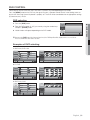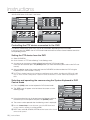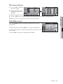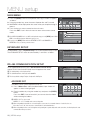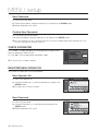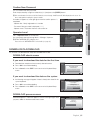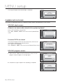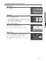
1
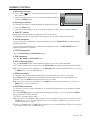
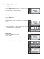
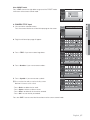
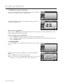
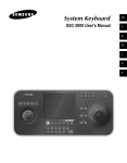
SSC-5000 System Keyboard user manual imagine the possibilities Thanks you for purchasing this Samsung product. To receive a more complete service, please register your product at www.samsung.com/global/register general facts CAUTION RISK OF ELECTRIC SHOCK. DO NOT OPEN This symbol indicates that dangerous voltage consisting a risk of electric shock is present within this unit. CAUTION : TO REDUCE THE RISK OF ELECTRIC SHOCK, DO NOT REMOVE COVER (OR BACK) NO USER-SERVICEABLE PARTS INSIDE REFER SERVICING TO QUALIFIED SERVICE PERSONNEL This symbol indicates that there are important operating and maintenance instructions in the literature accompanying this unit. WARNING • To reduce the risk of fire or electric shock, do not expose this appliance to rain or moisture. • To prevent injury, this apparatus must be securely attached to the floor/wall in accordance with the installation instructions. • If this power supply is used at 240V ac, a suitable plug adapter should be used. 1. Be sure to use only the standard adapter that is specified in the specification sheet.Using any other adapter could cause fire, electrical shock, or damage to the product. 2. Incorrectly connecting the power supply or replacing battery may cause explosion, fire, electric shock, or damage to the product. 3. Do not connect multiple cameras to a single adapter. Exceeding the capacity may cause abnormal heat generation or fire. 4. Securely plug the power cord into the power receptacle. Insecure connection may cause fire. 5. When installing the camera, fasten it securely and firmly. A falling camera may cause personal injury. 6. Do not place conductive objects (e.g. screwdrivers, coins, metal things, etc.) or containers filled with water on top of the camera. Doing so may cause personal injury due to fire, electric shock, or falling objects. 7. Do not install the unit in humid, dusty, or sooty locations. Doing so may cause fire or electric shock. 8. If any unusual smells or smoke come from the unit, stop using the product. In such case, immediately disconnect the power source and contact the service center. Continued use in such a condition may cause fire or electric shock. 9. If this product fails to operate normally, contact the nearest service center. Never disassemble or modify this product in any way. (SAMSUNG is not liable for problems caused by unauthorized modifications or attempted repair.) 10. When cleaning, do not spray water directly onto parts of the product. Doing so may cause fire or electric shock. CAUTION 1. Do not drop objects on the product or apply strong shock to it. Keep away from a location subject to excessive vibration or magnetic interference. 2. Do not install in a location subject to high temperature (over 122°F), low temperature (below 14°F), or high humidity. Doing so may cause fire or electric shock. 3. If you want to relocate the already installed product, be sure to turn off the power and then move or reinstall it. 4. Remove the power plug from the outlet when then there is a lightning. Neglecting to do so may cause fire or damage to the product. 5. Keep out of direct sunlight and heat radiation sources. It may cause fire. 6. Install it in a place with good ventilation. 7. Avoid aiming the camera directly towards extremely bright objects such as sun, as this may damage the CCD image sensor. 8. Apparatus shall not be exposed to dripping or splashing and no objects filled with liquids, such as vases, shall be placed on the apparatus. 9. The Mains plug is used as a disconnect device and shall stay readily operable at any time. 2_ general facts FCC STATEMENT This device complies with part 15 of the FCC Rules. Operation is subject to the following two conditions: 1) This device may not cause harmful interference, and 2) This device must accept any interference received including interference that may cause undesired operation. This equipment has been tested and found to comply with the limits for a Class A digital device, pursuant to part 15 J FCC regulations state that any unauthorized changes or modifications to this equipment may void the of FCC Rules. These limits are designed to provide reasonable protection against harmful interference when the equipment is operated in a commercial environment. This equipment generates, uses, and can radiate radio frequency energy and, if not installed and used in accordance with the instruction manual, may cause harmful interference to radio communications. Operation of this equipment in a residential area is likely to cause harmful interference in which case the user will be required to correct the interference at his own expense. user’s authority to operate it. IC Compliance Notice This Class A digital apparatus meets all requirements of the Canadian interference-Causing Equipment Regulations of ICES-003. IMPORTANT SAFETY INSTRUCTIONS 1. Read these instructions. 2. Keep these instructions. 3. Heed all warnings. 4. Follow all instructions. 5. Do not use this apparatus near water. 6. Clean only with dry cloth. 7. Do not block any ventilation openings. Install in accordance with the manufacturer’s instructions. 8. Do not install near any heat sources such as radiators, heat registers, or other apparatus (including amplifiers) that produce heat. 9. Do not defeat the safety purpose of the polarized or grounding-type plug. A polarized plug has two blades with one wider than the other. A grounding type plug has two blades and a third grounding prong. The wide blade or the third prong is provided for your safety. If the provided plug does not fit into your outlet, consult an electrician for replacement of the obsolete outlet. 10. Protect the power cord from being walked on or pinched particularly at plugs, convenience receptacles, and the point where they exit from the apparatus. 11. Only use attachments/accessories specified by the manufacturer. 12. Use only with the cart, stand, tripod, bracket, or table specified by the manufacturer, or sold with the apparatus. When a cart is used, use caution when moving the cart/apparatus combination to avoid injury from tip-over. 13. Unplug this apparatus during lightning storms or when unused for long periods of time. 14. Refer all servicing to qualified service personnel. Servicing is required when the apparatus has been damaged in any way, such as power-supply cord or plug is damaged, liquid has been spilled or objects have fallen into the apparatus, the apparatus has been exposed to rain or moisture, does not operate normally, or been dropped. CALIFORNIA USA ONLY This Perchlorate warning applies only to primary CR (Manganese Dioxide) Lithium coin cells in the product sold or distributed ONLY in California USA. “Perchlorate Material - special handling may apply, See www.dtsc.ca.gov/ hazardouswaste/perchlorate.” English _3 M GENERAL FACTS M general facts CONTENTS GENERAL FACTS 2 INSTALLATION 8 CONNECTING WITH OTHER EQUIPMENT 10 INSTRUCTIONS 14 MENU SETUP 22 OTHERS 29 4_ general facts 4 5 5 6 Contents Introduction Checking Contents & Accessories Name and function of each part 8 8 9 9 Installation Environment Setup Cautions for Installation Adjusting System Keyboard Angle Fixing Power Cord 10 12 12 13 Connecting RS-485 Device Connecting to PC using USB port Connecting Other System Keyboard Basic System Diagram of SSC-5000 14 15 19 Log-in Camera control DVR control 22 22 22 23 24 24 25 26 27 28 Main Menu Keyboard Setup RS-485 Communication Setup Change Password Check Password Register New Operator Camera Data Download Camera Data Upload System Information and Setup Operator Level 29 30 Product Specification Troubleshooting (FAQ) INTRODUCTION SSC-5000 system keyboard is a controller that controls Cameras, DVR, and other devices by using RS-485. An user-friendly on-screen menu, touch screen, and joystick applied, it is easy to operate. Features W Controllable products List • Camera • DVR SHR-4081, SHR-4160, SHR-504Xseries, 508Xseries, 516Xseries, SHR-2XXXseries, PC Based DVR (SPR-7XXXseries, SPR-9XXXseries) CHECKING CONTENTS & ACCESSORIES On buying a product, unwrap it first and put it down on a plane or where you want to use it. Then, you shall check if the followings are contained in the box. rd boa tem Key Sys Main Body User’s Manual English _5 M GENERAL FACTS • Long-distance remote control Through RS-485 communication, remote control is possible up to 1.2 kilometers. (Based on the one System Keyboard) • Integrated System Control A System Keyboard can control Camera (Receiver Unit) and DVR. • You can connect 2 or more System Keyboards together. Maximum 32 keyboards can be connected simultaneously and the system can be controlled from different places. • Easy to operate There is an LCD showing the operating status of the System Keyboard, Touch Screen that helps users to choose the menu easily, and a Joystick. general facts NAME AND FUNCTION OF EACH PART Front side Name Function LCD Display It shows the operating status of the system keyboard.. Camera movement button PRESET, PATTERN, SCAN, AUTO PAN ALARM RESET button Use this to set on or off the alarm. Camera lens button - IRIS control (IRIS CLOSE/OPEN) - FOCUS control (FOCUS NEAR/FAR) - ZOOM control (ZOOM TELE/WIDE) Joystick controller (UP/ DOWN/LEFT/DOWN/ZOOM) The Pan/Tilt connected with Samsung Dome Camera or Receiver Unit is moved to UP/ DOWN/LEFT/RIGHT. Press the button on the top of Joystick to control the Auto Focus. And use for the zoom control by turning to the clockwise or counterclockwise. The function of UP/DOWN/LEFT/RIGHT keys is controlled in the menu screen of the connected controller. Press the button of the top to execute ENTER motion. Device select button (MON/CAM/VMS/DVR) This key is to select Camera, Monitor, DVR or others. DVR control button (SEQUENCE, MODE) - SEQUENCE : Executes the SEQUENCE function of DVR. - MODE : Executes the partition screen selection function of DVR. Number (0~9), ENTER, CLEAR button This key is to select Camera, Monitor, DVR, Preset, Pattern Number, or others. MENU button This key is to go into the menu mode for the setup of various devices. Jog shuttle - JOG : Is in use for Forward / Reverse Frame search in the playback mode of DVR. - Shuttle : Executes the Play / Reverse Play / FF / REW functions in the playback mode of DVR. DVR Play button PLAY/PAUSE, STOP, FAST FORWARD, REWIND, RECORD AUX 1, 2, 3, 4 button Controls the AUX output of the receiver unit. 6_ general facts Back side M GENERAL FACTS Name Function USB Port This is a software uploading port of the System Keyboard. Composite Video IN/OUT This is an AV In / Out port. RS-485 (Port1, 2) For RS-485 communication, it will be connected to the RS-485 terminals of other System Keyboards or controlling devices such as cameras, and DVR. MYou can specify different protocols for Port 1 and Port 2. DC12V IN DC 12V power input terminal English _7 installation INSTALLATION ENVIRONMENT SETUP The following information is prepared for safe installation of the unit. • This unit can be placed on a flat table or installed in the rack. It should not be used vertically or skew, but horizontally. • The location of the unit and the composition of wiring are very important in properly operating the system. When equipment is placed too close or if ventilation is not properly done, system may not work properly, and maintenance of the system may be difficult. • In order to prevent system failure and to reduce system shut-down by outside environmental factors, air circulation in the system operating room, and the cover of the unit must be fixed. • Do not open the cover voluntarily because high voltage within the unit may cause electric shock. PHYSICAL & ENVIRONMENTAL - Operating Temperature : 0°C ~ 40°C Maintenance Temperature : -20°C~60°C Operating Humidity : 20%~85% RH Maintenance Humidity : 20%~90%RH Power Supply : DC 12V, 1A ( ) Power Consumption : 4W J When system is operated, input voltage range must be within 10% of nominal voltage, and power consent should be grounded. Heating devices such as hair dryer, iron, refrigerator should not be used together. For safe power supply, AVR (Automatic Voltage Regulator) is recommended. The connector linked to this equipment can affect EMI, so it is recommended to coil the CORE-FERRITE for use. CAUTIONS FOR INSTALLATION - Be sure to turn the unit off before installing. Avoid shock or vibration since they may cause unit malfunction. Keep away from magnets, radio or TV to avoid magnetic damage. During or after installing the unit, be sure to maintain the area around the unit clean. Place the unit on a flat surface and maintain temperature properly. Allow 15 cm of clearance between the rear panel and the wall. Be careful not to drop any conductive materials into the hole for ventilation. When replacing built-in fuse, be sure to turn the power off, and unplug the unit. Avoid locating the unit where direct sunlight will fall, and maintain it cool. Keep tools and equipment away from people so that they would not be hurt. If ignoring smoke or smell while using the unit, fire or electric shock may occur. In this case, turn the power switch off immediately, and consult professionals in the closest service center. Be sure to check dangers, which may occur due to damped floor, ungrounded power extension cable, worn power cord or lack of safety grounding. J When cleaning this unit, be sure to wipe with a dried cloth. If the unit is heavily contaminated, wipe it with a soft cloth dampened with a mild detergent solution, then wipe dry with a soft clean cloth. Do not use chemicals such as alcohol, benzene, or thinner because a chemical reaction could result permanent damaging of the cabinet surface. 8_ installation ADJUSTING SYSTEM KEYBOARD ANGLE You may adjust the angle of the product as shown below. M INSTALLATION FIXING POWER CORD Hang the power cord as shown in the following figure to prevent it from being deviated when you connect it with the main body. English _9 connecting with other equipment You can use the SSC-5000 System Keyboard with a camera, DVR, and the other equipments. This chapter describes how to connect each equipment. CONNECTING RS-485 DEVICE - Connect RS-485 Device through the port in the back of SSC-5000. - You are able to install and control the camera and DVR supporting RS-485 communication. - Either Half Duplex or Full Duplex method is applicable for connection. M For the Half Duplex method, use TX +,-. M To connect RS-485, be careful not to be confused between + and -. Also, you shall check if the RS-485 device can support SSC-5000. M Please refer to “RS-485 Communication Setup” of “Menu Setup” for RS-485 communication setup. (see page 22) Connecting the SAMSUNG Dome Camera Connect with SSC-5000 by using the RS-485 port on the back of Dome Camera W In case of connecting with Half Duplex - Connect the RX (+) of Dome Camera RS-485 port with the TX(+) of SSC-5000. - Connect the RX (-) of Dome Camera RS-485 port with the TX(-) of SSC-5000. W In case of connecting with Full Duplex - Connect the RX (+) of Dome Camera RS-485 port with the TX (+) of SSC-5000. - Connect the RX(-) of Dome Camera RS-485 port with the TX (-) of SSC-5000. - Connect the TX (+) of Dome Camera RS-485 port with the RX (+) of SSC-5000. - Connect the TX (-) of Dome Camera RS-485 port with the RX (-) of SSC-5000. 10_ Connecting with Other Equipment TXD+ TXDRXD+ RXD- Connecting SHR-4081, SHR-4160, SHR-508X Series, SHR-516X Series, SHR-208X and SHR-216X Series DVRs Connect to SSC-5000 through the RS-485 port on the rear of the DVR. W Connecting as Half Duplex - Connect TX (+) of the RS-485 port of the DVR to TX (+) of SSC-5000. - Connect TX (-) of the RS-485 port of the DVR to TX (-) of SSC-5000. M CONNECTING WITH OTHER EQUIPMENT W Connecting as Full Duplex - Connect RX (+) of RS-485 port of the DVR to RX (+) of SSC-5000. - Connect RX (-) of RS-485 port of the DVR to RX (-) of SSC-5000. - Connect TX (+) of RS-485 port of the DVR to TX (+) of SSC-5000. - Connect TX (-) of RS-485 port of the DVR to TX (-) of SSC-5000. Connecting SHR-5040 & SHR-5042 DVR Connect to SSC-5000 through the RS-485 port on the rear of SHR-5040 / SHR-5042DVR. W Connecting as Half Duplex - Connect TX (+) of RS-485 port of SHR-5040 / SHR-5042 DVR to TX (+) of SSC-5000. - Connect TX (-) of RS-485 port of SHR-5040 / SHR-5042 DVR to TX (-) of SSC-5000. Connecting SHR-204X Series DVR Connect to SSC-5000 through the RS-485 port on the rear of SHR-204X DVR. W Connecting as Half Duplex - Connect TX (+) of RS-485 port of SHR-204X Series DVR to TX (+) of SSC-5000. - Connect TX (-) of RS-485 port of SHR-204X Series DVR to TX (-) of SSC-5000. W Connecting as Full Duplex - Connect RX (+) of RS-485 port of SHR-204X Series DVR to RX (+) of SSC-5000. - Connect RX (-) of RS-485 port of SHR-204X Series DVR to RX (-) of SSC-5000. - Connect TX (+) of RS-485 port of SHR-204X Series DVR to TX (+) of SSC-5000. - Connect TX (-) of RS-485 port of SHR-204X Series DVR to TX (-) of SSC-5000. English _11 connecting with other equipment Connecting PC Based DVR - Connect SSC-5000 through the RS-485 port in the back of PC Based DVR. - Connect SIGNAL (+) in the RS-485 port of PC Based DVR with TX (+) of SSC-5000. - Connect SIGNAL (-) in the RS-485 port of PC Based DVR with TX (-) of SSC-5000. <SPR-9XXX Series> <SPR-7XXX Series> CONNECTING TO PC USING USB PORT You can use the provided USB cable to connect to the PC with uploading software for updating software of the System Keyboard. CONNECTING OTHER SYSTEM KEYBOARD ※ It is possible to connect and use max. 32 keyboards simultaneously. ※ Refer to the “ADDRESS SET” part in “RS-485 Communication Setup” of “Menu Setup” for the setting of keyboard communication. (see page 22) ※ Do not use together with the SSC-2000/SSC-1000 because it is different with the SSC-2000/SSC-1000 in communication method. W In case of connecting with Half Duplex - Connect the TX (+) of SSC-5000 port with the TX(+) of another SSC-5000. - Connect the TX (-) of SSC-5000 port with the TX(-) of another SSC-5000. W In case of connecting with Full Duplex - Connect the TX (+) of SSC-5000 with the TX (+) of another SSC-5000. - Connect the TX (-) of SSC-5000 with the TX (-) of another SSC-5000. - Connect the RX (+) of SSC-5000 with the RX (+) of another SSC-5000. - Connect the RX (-) of SSC-5000 with the RX (-) of another SSC-5000. 12_ Connecting with Other Equipment BASIC SYSTEM DIAGRAM OF SSC-5000 1. One Keyboard to One Device Digital Video Recorder Digital Video Recorder Digital Video Recorder 3. Multiple Keyboards to Multiple Devices (“Daisy-Chain”Type Wiring) Digital Video Recorder Digital Video Recorder M Do not use together with the SSC-2000/SSC-1000 because it is different with the SSC-2000/SSC-1000 in communication method. In case of using the keyboard connected SSC-931T Version 1.4, make sure the address of connected keyboards differ from each other. English _13 M CONNECTING WITH OTHER EQUIPMENT 2. One Keyboard to Multiple Devices (“Daisy-Chain” Type Wiring) instructions LOG-IN 1. Turn on the power of all the components of the system. 2. When the power is applied by connecting the power adapter at the back of system keyboard, the following indication is displayed on the LCD screen. Login Operator No. Password Clear Enter 3. Using the keypad of the touch screen or the number key of the keyboard, enter the registered Operator number (1~32) and press <Enter>. Login Error No. The default Operator No. is 1. Invalid Operator! Clear Refer to “MENU setup”, “REGISTER NEW OPERATOR” for the registration of the operator number. (see page 24) M If an unregistered operator number is entered, a message of “Invalid Operator!” will appear on the screen and the log-in process will return to the starting point automatically. Enter Login Error No. 4. Using the number keys, enter the registered Password (6-digit figure) and press <Enter>. Invalid Password! Clear M The default Password is 4321. Refer to “MENU setup”, “REGISTER NEW OPERATOR” for the registration of the password. (see page 24) M If an unregistered password is entered, a message of “Invalid Password!” will appear on the screen and the log-in process will return to the starting point automatically. Enter CAM 002 MON 5. When you have logged in successfully, the System Keyboard will enter the following camera control mode and display “Normal Mode” or “Video Mode” as in the right figure. To change the display mode, see “Display Mode” in “System Information & Setup”. (see page 27) M Simply tap the screen if you want to switch from the current mode to other mode. M If the key board is not operated for three minutes, the graphic panel is changed to the sleep mode and the screen is not displayed. (Samsung Logo display) Press the touch panel/key or move the joystick/jog shuttle, and then the screen before the sleep mode is displayed again. 002 CAM 002 MON 002 6. If you want to log out, press and hold both [PRESET] and [ALARM RESET] buttons simultaneously for more than 2 seconds to display the Login dialog. 14_ instructions CAMERA CONTROL W Selecting a camera 1. Press “CAM” ( be as follows. ) key. The camera display part of the screen will 2. Enter the camera number (0~255) you want by using the number key and press [ENTER] button. CAM 002 MON 002 W Selecting a monitor 1. Press the [MON] button. 2. Enter the monitor number(0~255) that shows the image of the chosen camera and press <Enter>. W PAN/TILT control Move the joystick of the keyboard to regulate PAN/TILT of the camera. The speed of the camera movement gets faster when the joystick moves farther from the center. W ZOOM movement Turn the joystick of the keyboard in a clockwise direction or press the [ZOOM TELE] button to regulate the ZOOM IN movement. Turn the joystick of the keyboard in a counterclockwise direction or press the [ZOOM WIDE] button to regulate the ZOOM OUT movement. W FOCUS movement Press the [FOCUS FAR] or [FOCUS NEAR] button. W IRIS movement Press the [IRIS OPEN] or [IRIS CLOSE] button. W AUTO PAN movement Press the [AUTO PAN] button to move between two points in the camera menu repeatedly. “AUTO PAN” will appear on the screen. Press the [AUTO PAN] button again to release the auto pan mode. M On models released later than the SCC-C6405, press the [AUTO PAN] button and enter the AUTO PAN number (1~4), then press the [ENTER] button to execute the AUTO PAN feature. W SCAN movement This function is to move between the preset positions that were set by the camera's scan mode. Press [SCAN] button to execute the scan movement and you will see “SCAN” message during the scan movement. Press the [SCAN] button again to release the scan mode. M On models released later than the SCC-C6405, press the [SCAN] button, and enter the SCAN number (1~4), then press the [ENTER] button to execute the SCAN feature. W PATTERN movement This function is to view the camera movement for 30 seconds designated by the user on the pattern mode of the camera menu. Press the [PATTERN] button on the keyboard, enter the pattern number(1~3) you want, and press [ENTER] button to execute PATTERN movement. “PATTERN 1” will appear on the screen. M On models later than the ALARM VER 1.100, SCC-C6405, movements caught by the camera for 2 minutes will be stored in the PATTERN feature (1~3). If you are transferring data from and to the camera with SSC-5000, please reset before use since the PATTERN may differ from the settings. M If there is any of MANUAL (PAN, TILT, ZOOM, FOCUS) input during auto execution (SCAN, AUTO PAN, PATTERN), the system will stop the AUTO movement and execute the MANUAL movement. English _15 M INSTRUCTIONS This function is to choose a monitor displaying the image of the camera. instructions W PRESET movement Press the [PRESET] button on the keyboard to start PRESET POSITION movement. The screen will appear as shown in the right figure. Preset CAM 000 MON Save 001 Delete PRESET position movement 1. Enter the preset number you want to operate. 2. Press [ENTER] button. PRESET programming This function is to set the camera screen the user wants to call and monitor whenever he/she wants to. Maximum 128 screens can be preset. (0~127) Preset CAM 000 MON Save 001 1. Move the camera to the position you want by using a joystick and camera lens key. Delete 2. Press <Save>. 3. When a window appears as shown in the right figure, enter the preset number you want to save and press <Enter>. CAM Input Preset No. (0~127) 000 MON 001 Clear PRESET DELETE This function is to delete the preset position. 1. Press <Delete>. 2. When a window appears as shown in the right figure, enter the preset number you want to delete and press <Enter>. 3. The camera will move to the preset position you want to delete. The system keyboard will show a message to confirm the deletion. Press <OK> to delete or <Cancel> to cancel the order. Enter Preset CAM 000 MON Save 001 Delete CAM Input Preset No. (0~127) 000 MON 001 Clear CAM Enter Input Preset No. (0~127) 000 MON 001 Are you sure you want to delete preset 005? Cancel 16_ instructions OK Clear PRESET mode Press <EXIT> icon on the right below to go out of the PRESET mode. It will return to the camera control mode. Preset CAM 000 MON Save 001 Delete 1. You can title the selected camera. Press the camera title line to call the title input page on the screen. M INSTRUCTIONS W CAMERA TITLE input CAM 000 MON 001 2. English small letter input page will appear. CAM 000 MON 001 3. Press <TEXT> if you want to enter large letters. TEXT text Number Symbol Back Space Clear OK TEXT text Number Symbol Back Space Clear OK TEXT text Number Symbol Back Space Clear OK TEXT text Number Symbol Back Space Clear OK CAM 000 MON 001 4. Press <Number> if you want to enter numbers. CAM 000 MON 001 5. Press <Symbol> if you want to enter symbols. CAM M Press a word at a time until you complete the title you want. Maximum 14 characters can be entered. 000 - MON 001 Press <Back> to delete the last word. Press <Space> to leave a column vacant. Press <Clear> to delete all the characters entered. Press <OK> to save the title you entered. Press the <EXIT> icon to cancel the title and return to the camera control mode. English _17 instructions W CAMERA connection information Press the part marked as shown in the right figure to know the number of DVR that are connected to the selected camera. CAM 000 MON 001 A window will appear as shown in the right figure when you press the camera number display part. Connecting Info. CAM 000 MON 001 CAM DVR 000 001 Move to the connected device When you press <DVR 001> on the connection information screen, DVR 001 will be selected and the screen will be changed into the DVR control mode. Enter the number of the connected DVR 1. Press the [DVR] button of the keyboard on the connection information screen. 2. While the number is highlighted, enter the number of the connected DVR by using the number keys and press the [ENTER] button. W CAMERA MENU Press the <SETUP> icon on left below to control the menu of the selected camera. CAM 000 MON 001 Using the direction key and the <Enter> key, control the CAMERA MENU. Press the <EXIT> icon to clear the camera menu. M When you control the menu of SAMSUNG DOME CAMERA, you can use the joystick as a direction or enter key by moving it or after pressing the AF button of it. 18_ instructions CAM Camera Setup 000 Enter DVR CONTROL Please refer to the manual of each DVR since DVR’s functions are varied depending on the model. Press the [MENU] button on the DVR set, then go to “System Remote Control Device” in the Settings menu to ensure that "Samsung System Keyboard" is properly set. The DVR will be controllable after the appropriate settings (ID, baud rate, etc.) are set. DVR selection CAM 2. Enter the DVR number (0~255) you want by using the number keys and press [ENTER] button. MON 3. Varied window will appear depending on the DVR model. DVR 000 001 000 M If you press the [DVR] button in the Camera Control mode, the DVR Input Box will be displayed in the screen as follows. Then, select DVR in the same manner as above. Examples of DVR selecting 1. SHR-4081, SHR-4160 DVR Record Mode DVR 013 Panic Freeze 013 REC Lock Zoom SHR-4081 MON 000 Select Channel SHR-4081 MON 001 Search Alarm 2. PC DVR DVR 011 SPR7416 MON 000 4 div. Search DVR 9 div. Emergency Rec 011 16 div. Alarm Off Select Channel SPR7416 MON 000 Rotate 3. SHR-5040, 5042 DVR Search Zoom DVR 002 Record Audio 002 Alarm Eject SHR-5042 MON 000 Mode Select Channel SHR-5042 MON 002 Freeze English _19 M INSTRUCTIONS 1. Press the [DVR] button. instructions 4. SHR-2XXX Series, SHR-508X, 516X Series DVR Record Mode DVR 012 Search Freeze 012 Alarm Zoom Audio Eject SHR-5082 MON 000 DVR Select Channel Select Channel SHR-5162 MON 000 DVR 002 002 SHR-5082 SHR-2042 MON MON 002 002 Select Channel Controlling the PTZ device connected to the DVR PTZ devices connected to some DVRs may not be controllable, depending on the DVR model. In this case, press the <EXIT> icon in DVR Control mode and move to Camera Control mode to control the corresponding camera. Setting the PTZ device from the DVR 1. Select DVR MENU. 2. Go to “Camera PTZ Device Settings” in the Settings menu. 3. A screen to set the camera available will be displayed in the DVR Control mode. Enter each item and then press the [ENTER] button. (For more information, please refer to the DVR user manual.) 4. After completing setup of the camera, exit from the DVR MENU and then reselect the DVR using the keyboard (DVR + DVR number + ENTER). M The PTZ Device Settings feature from the Settings menu and Camera may be enabled, depending on the DVD model. In this case, set “Device” from the “Settings menu System Remote Control Device” as “None” and then try resetting the PTZ device. Selecting and operating the camera using the System Keyboard in DVR Control mode 1. Press the [CAM] button on the keyboard in DVR Control mode. 2. The <PTZ> icon will appear at the left side of the screen as in the following image. 3. Using the number keys on the keypad, enter the Channel number of the camera you wish to operate and press the [ENTER] button. 4. The camera can be operated after the following screen is displayed. M Press the <Camera Setup> icon at the bottom center of the DVR Control mode screen to control the currently selected Camera MENU. M PRESET feature and SCAN, AUTO PAN, PATTERN and other features of the selected camera can be operated. 20_ instructions DVR Record Mode 002 Search Freeze SHR2042 Alarm Zoom 000 Audio Eject DVR Record Mode 002 Search Freeze Alarm Zoom Audio Eject MON SHR2042 MON 000 01 DVR channel selection 1. Press the <CH> icon below on the DVR screen. 2. A channel selection screen will appear as shown in the right figure. DVR 011 SPR7416 MON 000 4 div. Search DVR 9 div. Record 011 16 div. Alarm Off Rotate Select Channel SPR7416 MON 000 3. Select the channel you want. M INSTRUCTIONS 4. Press the <EXIT> icon on the lower right to finish selecting and return to the DVR control screen. M DVR channel can be selected by using the number keys (0~9) of the keyboard. DVR MENU control Press the <SETUP> icon on the lower left to control the menu of the selected DVR. DVR DVR Setup 000 SPR7416 Enter Using the Direction key and the <Enter> key, control the DVR MENU. You can use the joystick as a direction or enter key by moving it or using the AF button. Press the <EXIT> icon to finish controlling the DVR MENU. English _21 MENU setup MAIN MENU 1. Press the [MENU] button of the keyboard and a log-in window will appear as follows. Login Operator No. 2. Using the number keys, enter the correct Operator No. and Password. Password 3. MAIN MENU will be displayed on the screen when you complete the log-in process. 4. Press the item you want to control on the main menu. Press the <EXIT> icon in the main menu to return to the camera control mode. Clear Enter MENU MAIN Keyboard Setup Camera 000 Setup DVR 001 Setup M If the CHECK PASSWORD item is set “Off” in the keyboard setup, press the [MENU] button. MAIN MENU screen will directly appear without the log-in process. M If you press the [MEMU] button while the OPERATOR’s LEVEL is the MANAGER’s or OPERATOR’s level, you cannot go into the menu. KEYBOARD SETUP On MAIN MENU, press <Keyboard Setup> to call the Keyboard Setup screen. The KEYBOARD SETUP menu are constituted by 7 main items as follows. Keyboard Setup RS-485 Communication Setup Change Password Check Password On Register New Operation Camera Data Download Camera Data Upload System Information and Setup RS-485 COMMUNICATION SETUP On the Keyboard Setup menu, press <RS-485 Communication Setup> and the RS-485 Communication Setup menu will appear on the screen. Keyboard Setup M The default address of the keyboard is 0. M The default Baud Rate of the keyboard is 9600BPS. RS-485 Communication Setup ¨Address Set 0 ¨Protocol (Port 1) SAMSUNG ¨Protocol (Port 2) SAMSUNG ¨Baud Rate 9600 ¨Duplex Half Duplex M The factory default setting of Duplex of keyboard is Half Duplex. ADDRESS SET The address of the system keyboard can be set. 1. Press <Address Set> and the keyboard address input window will appear as shown in the right figure. 2. Enter the address by using the number keys and press the [ENTER] button. Press the <EXIT> icon on lower left if you want to clear the window without entering the address. Keyboard Setup Input Keyboard Address (0~32) Clear Enter M ADDRESS "0": For only one unit ADDRESS "1~32": For multiple units connected together M When using multiple units that are connected together, you must select a number between 1 and 32 before use. If the value is set to "0", this may cause communication to fail and malfunction. M When using multiple units connected together and operating two separate keyboards at the same time, the first keyboard to start communication takes precedence. 22_ MENU setup Protocol Port1/Port2 The protocol of the RS-485 communication can be set. RS-485 communication of the system keyboard supports Camera Protocol as follows. Keyboard Setup Choose one protocol among SAMSUNG / Pelco-D / Pelco-P / Vicon / Panasonic / Kalatel / Diamond / AD / Philips / Erna / VCL TP / Techwin / Honeywell. M The multimedia protocol provided by us may not be supported depending on the installation conditions. Please contact us or the store of your purchase if you have a problem or question about installing the protocol. Kalatel Diamond Keyboard Setup Honeywell RS-485 Communication Setup ¨Address Set 0 AD SAMSUNG ¨Protocol Pelco-D 1(Port 1) SAMSUNG Philips ¨Protocol Pelco-p 1(Port 2) SAMSUNG Erna ¨Baud Rate 9600 Vicon VCL TP ¨Duplex Panasonic Half Duplex Techwin Kalatel Diamond Honeywell Baud Rate The Baud Rate of the RS-485 communication can be set. Keyboard Setup 1. Press <Baud Rate> and a pop-up window will appear as shown in the right figure. RS-485 communication of the system keyboard supports Baud Rate as follows. RS-485 Communication Setup ¨Address Set 0 1200 ¨Protocol (Port 1) SAMSUNG 2400 ¨Protocol (Port 2) SAMSUNG ¨Baud Rate 9600 4800 9600 ¨Duplex Half Duplex 19200 38400 2. 1200/ 2400/ 4800/ 9600/ 19200/ 38400. Among these 6 kinds of Baud Rate, select one Baud Rate. Duplex 1. You can set the duplex mode of system keyboard. Press <Duplex>, and then the following window pops up. Keyboard Setup 2. Full Duplex / Half Duplex. Select one of the two duplex. RS-485 Communication Setup ¨Address Set 0 ¨Protocol (Port 1) SAMSUNG ¨Protocol (Port 2) SAMSUNG ¨Baud Rate 9600 ¨Duplex Half Duplex Full Duplex Half Duplex M Press the <EXIT> icon on the lower left to finish RS-485 COMMUNICATION SETUP control and return to the KEYBOARD SETUP screen. CHANGE PASSWORD This function is to change the operator's password of the system keyboard. Keyboard Setup Change Password Enter Operator No. Enter Password Clear Enter 1. At first, enter the current Operator No. and Password. 2. Correctly entered, the screen will change into a window as follows. Keyboard Setup Change Password Enter New Password ¾¾¾¾¾¾ Confirm New Password ¾¾¾¾¾¾ Clear Enter English _23 M MENU SETUP M You can control two protocols simultaneously by specifying different protocols for Port 1 and Port 2. RS-485 Communication Setup ¨Address Set 0 AD SAMSUNG ¨Protocol Pelco-D 1(Port 1) SAMSUNG Philips ¨Protocol Pelco-p 1(Port 2) SAMSUNG Erna ¨Baud Rate 9600 Vicon VCL TP ¨Duplex Panasonic Half Duplex Techwin MENU setup New Password 1. Enter the new password. 2. Enter the password by using the number keys (0~9) and press the [ENTER] button. M Maximum 6-digit figure can be entered. Confirm New Password This is to confirm the new password. Enter the password by using the number keys (0~9) and press the [ENTER] button. M If the entered number is not same as the New Password, an error message “Invalid Password!!” will be displayed on the screen. You have to start again from entering the operator no. CHECK PASSWORD If it is set <On>, a window will appear to ask the operator no. and password when you entering the “MENU” screen. Keyboard Setup If it is set <Off>, you can directly enter the “MENU” mode. RS-485 Communication Setup Change Password Check Password On Register New Operater Off Camera Data Download Camera Data Upload System Information and Setup M The system has been set <On> on shipment. REGISTER NEW OPERATOR This function is to add a new user of the keyboard. New Operator No. 1. Enter a new operator no.. Keyboard Setup Register New Operator Enter Operator No. 2. Using the number keys 0~9, enter the operator no. and press the [ENTER] button. M The number can be one between 1 and 99. Clear Enter New Password 1. Enter a new password. 2. Using the number keys 0~9, enter the password and press the [ENTER] button. M Maximum 6-digit figure can be entered. Keyboard Setup Register New Operator New Password ¾¾¾¾¾¾ Confirm New Password ¾¾¾¾¾¾ Clear Enter 24_ MENU setup Confirm New Password This is to confirm the new password. Enter the password by using the number keys (0~9) and press the [ENTER] button. M If the entered number is not same as the New Password, an error message “Invalid Password!!” will be displayed on the screen. You have to start again from entering the operator's number. A window will appear as in the right figure when the confirm process is completed. Keyboard Setup RS-485 Communication Setup ¨Operator No. 2 ¨Password ¾¾¾¾¾¾ ¨Operator Level Operator - Password : New password is displayed. (******) - Operator Level : The level of the new user can be set. Operator Level Press <Operator Level> to set the level. You can choose one level among Admin. / Manager / Operator. Keyboard Setup M DEFAULT OPERATOR LEVEL is Operator level. Please refer to the ”OPERATOR LEVEL” for the details. (see page 28) RS-485 Communication Setup ¨Operator No. 2 ¨Password ¾¾¾¾¾¾ Admin. ¨Operator Level Operator Manager Operator CAMERA DATA DOWNLOAD This function is to download the setup data of SAMSUNG DOME. DOWNLOAD check screen If you want to download the data for the first time 1. Download the setup data of the currently selected camera. Keyboard Setup 2. Press <OK> to start downloading. Camera Data Download Now, Starting download Camera 000 data. 3. Press <Cancel> or the <EXIT> icon to return to the Keyboard Setup screen. Cancel OK If you want to download the data on the system 1. An informing message will appear if there is already data stored in the system keyboard. Keyboard Setup 2. Press <OK> to start downloading. Camera Data Download Camera 000 data is already On your System. Now Overwriting this data with Camera 001 data. 3. Press <Cancel> or the <EXIT> icon to return to the Keyboard Setup screen. Cancel OK DOWNLOAD process screen A download process screen will appear as shown in the right figure when you press <OK> on the down load check screen. Keyboard Setup Camera Data Download Camera 000 Downloading...... English _25 M MENU SETUP - Operator No. : Newly registered use's number MENU setup A message will appear when downloading is completed. Keyboard Setup Camera Data Download Camera 000 Download Complete !! CAMERA DATA UPLOAD This function is to download the data set in SAMSUNG DOME CAMERA and upload them to a new camera. UPLOAD check screen If there is no camera data stored in the system keyboard Camera DATA uploading is not possible. Press <OK>, <Cancel>, <EXIT> icon to return to the Keyboard Setup screen. Keyboard Setup Camera Data Upload No Camera Data On your System. Cancel OK If camera DATA are stored A message will appear to inform that the camera data, which are now stored, will be uploaded to the selected camera. Press <OK> to start uploading. Press <Cancel> or <EXIT> icon to return to the Keyboard Setup screen. Keyboard Setup Camera Data Upload Now, Starting upload Camera 000 data to Camera 001. Cancel OK UPLOAD progress screen 1. When you press <OK> on the UPLOAD check screen, UPLOAD progress screen will appear as in the right figure. Keyboard Setup Camera Data Upload Camera 000 Uploading...... 2. Complete message will appear when uploading is completed. Keyboard Setup Camera Data Upload Camera 000 Upload Complete !! 26_ MENU setup SYSTEM INFORMATION AND SETUP S/W Version Displays the present version. It is not available to set. Keyboard Setup System Information and Setup S/W version v1.00_080531 ¨Language English ¨Load Factory Default ¨Display Mode Normal Displays the present Set language. 1. Press the <Language> to change the language. Keyboard Setup 2. System keyboard supports English / Français / Deutsch / Español / Italiano/ ĬŏōōņńŅ / Polski/ 中國語 / 한국어 / Ă&4,:5Ã3,±& / 日本語 / PORTUGUÊS / DUTCH / DANSK / HRVATSKI. Select a language among these languages. System Information and Setup English 한국어 S/W version 5000-02L Français ČESKY ¨Language English Deutsch TÜRKÇE ¨Load Factory Default Español 日本語 Italiano PORTUGUÊS ¨Display Mode Normal Русский Polski 中國語 DUTCH DANSK HRVATSKI Factory Default Setup Resets all of the menu values to the default value. Press <OK> to start the default setting. Keyboard Setup Load Factory Default Do you want to Load Factory Default? M The system will start again when the Factory Default Setup is completed. Cancel OK Display Mode 1. Press the <Display Mode> to change the display mode. 2. Set the default display mode to <Video> or <Normal>. M Your setting will be applied when you restart the system. Keyboard Setup System Information and Setup S/W version v1.00_080531 ¨Language English ¨Load Factory Default ¨Display Mode Normal Video Normal M To change the display mode, simply tap the screen if you want to switch from the current mode. English _27 M MENU SETUP Language MENU setup OPERATOR LEVEL There are 3 levels of user, who can be registered as a user, including Admin. / Manager / Operator. Admin is the highest level. The range and limit to the usage of various setup menu and system function depends on the user's level. Admin. Manager Operator Camera Setup O X X DVR Setup O X X PTZ Control in DVR Mode O O X Preset Save O X X Preset Delete O O X Save Camera Title O O X MENU Button O X X Save Connect Information O X X Save Connected Monitor O O X Move Jog/Shuttle O O X Move Joystick O O X DVR Search O O X DVR Search (including PLAY Button) O O X Record On/Off O O X Select Camera/DVR O O O Camera Setup in DVR Mode O X X 28_ MENU setup others PRODUCT SPECIFICATION Item Description CONNECTOR TYPE : 8P TERMINAL TYPE M OTHERS INTERFACE(RS-485) PORT : 2 PORT BAUD RATE : 1200 / 2400 / 4800 / 9600 / 19200 / 38400 bps 4.3" TFT LCD PANEL + TOUCH PANEL EFFECTIVE DISPLAY AREA : 95.040mm[H] x 53.856mm[V] TFT LCD PANEL NUMBER OF DOTS : 1440[H] x 272[V] DOT PITCH : 66.0㎛[H] x 198.0㎛[V] USB PORT (USB 2.0) S/W Upgrade VIDEO INPUT/OUTPUT Composite Video 1.0Vp-p, 75ohm, BNC Type, Loop Through out OSD 16 Language (Eng/Fre/Ger/Spa/Ita/Rus/Pol/Kor/Cze/Tur/Chi/Jpa/Bra(Port)/Neth/Denma/Croatia) Pelco-D, Pelco-P, Vicon, Panasonic, GE-Khalatel, Diamond, MULTI PROTOCOL(CAMERA) American Dynamic,Philips,Erna,VCLTP,Samsung Electronics ,Techwin, Honeywell JOY STICK LED 3D JOY STICK (PAN/TILT/ZOOM) MONITOR, CAMERA, DVR PAN : LEFT / RIGHT TILT : UP / DOWN IRIS : CLOSE / OPEN PAN/TILT & LENS CONTROL FOCUS : FAR / NEAR ZOOM : TELE / WIDE PRESET, PATTERN, AUTO PAN, SCAN AUX1, AUX2, AUX3, AUX4 Target : SAMSUNG DVR DVR CONTROL SW : RW, STOP, PLAY, FF, REC JOG/SHUTTLE : FORWARD/REVERSE, PLAY/REVERSE PLAY/FF/RW POWER POWER CONSUMPTION DC 12V 4W OPERATION TERPERATURE 0˚C ~ 40˚C OPERATION HUMIDITY RANGE 20 ~ 85% DIMENSIONS(WxHxD) WEIGHT 428mm x 137mm x 199mm 1.415Kg (NET) English _29 others TROUBLESHOOTING (FAQ) PROBLEM SOLUTION • Check the RS-485 communication line. The system keyboard communication is not worked. • Check the address setup of system keyboard. • Refer to “RS-485 Communication Setup” of “Menu Setup” for the method of address setup. (see page 22) • Supply power to the system keyboard while you are pressing the [MENU] and [ENTER] buttons on the keyboard simultaneously. The password in the screen of system log in is lost. • Press buttons until the “Beep” sounds. • System is reset to the factory default with a “Beep” sound. • Log in after the completion of reset. Refer to “Log-in” of “ Instructions” for the method of login. (see page 14) M Replace the LCD panel when its expected life is over. 30_ others Correct Disposal of This Product (Waste Electrical & Electronic Equipment) (Applicable in the European Union and other European countries with separate collection systems) This marking shown on the product or its literature, indicates that it should not be disposed with other household wastes at the end of its working life. To prevent possible harm to the environment or human health from uncontrolled waste disposal, please separate this from other types of wastes and recycle it responsibly to promote the sustainable reuse of material resources. Household users should contact either the retailer where they purchased this product, or their local government office, for details of where and how they can take this item for environmentally safe recycling. Business users should contact their supplier and check the terms and conditions of the purchase contract. This product should not be mixed with other commercial wastes for disposal. Code No. AB82-01969A-01