1
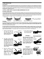
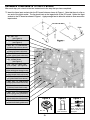
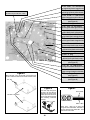
ANALOG MULTIMETER MODEL M-1150K Assembly and Instruction Manual Elenco Electronics, Inc. Copyright © 1995 Elenco Electronics, Inc. Revised 1997 REV-D 753012 PARTS LIST QTY SYMBOL VALUE RESISTORS COLOR CODE PART # r1 R26 .025Ω Shunt Wire 100269 r1 R12 .96Ω 1% 1/2W black-white-blue-silver-brown 109631 r1 R11 10Ω 1% 1/4W brown-black-black-gold-brown 121030 r1 R20 18.5Ω 1% 1/4W brown-gray-green-gold-brown 121832 r1 R10 102Ω 1% 1/4W brown-black-red-black-brown 131034 r1 R21 200Ω 1% 1/4W red-black-black-black-brown 132030 r1 R2 240Ω 1% 1/4W red-yellow-black-black-brown 132430 r1 R18 2KΩ 1% 1/4W red-black-black-brown-brown 142030 r1 R9 3KΩ 1% 1/4W orange-black-black-brown-brown 143033 r1 R3 5KΩ 1% 1/4W green-black-black-brown-brown 145030 r1 R24 18KΩ 1% 1/4W brown-gray-black-red-brown 151830 r1 R17 31KΩ 1% 1/4W orange-brown-black-red-brown 153130 r1 R22 34KΩ 1% 1/4W orange-yellow-black-red-brown 153430 r1 R4 40KΩ 1% 1/4W yellow-black-black-red-brown 154030 r1 R19 44KΩ 1% 1/4W yellow-yellow-black-red-brown 154430 r1 R13 83.3KΩ 1% 1/4W gray-orange-orange-red-brown 158330 r1 R5 150KΩ 1% 1/4W brown-green-black-orange-brown 161533 r1 R23 195KΩ 1% 1/4W brown-white-green-orange-brown 161930 r1 R14 360KΩ 1% 1/4W orange-blue-black-orange-brown 163630 r1 R6 800KΩ 1% 1/4W gray-black-black-orange-brown 168030 r1 R15 1.8MΩ 1% 1/2W brown-gray-black-yellow-brown 171831 r1 R7 4MΩ 1% 1/2W yellow-black-black-yellow-brown 174031 r1 R16 6.75MΩ 1% 1/2W blue-violet-green-yellow-brown 176731 r1 R8 15MΩ 1% 1W brown-green-black-green-brown 181532 r1 R1 680Ω Pot 191311 r1 R25 10KΩ Pot 191515 * NOTE: All fixed resistors are 1% tolerance (last stripe, brown). In some cases, resistors with a .5% tolerance (last stripe, green) may be used in place of the 1% resistors. Please ignore the tolerances printed on the resistor card. QTY SYMBOL VALUE CAPACITORS MARKING QTY SYMBOL VALUE SEMICONDUCTORS DESCRIPTION r1 C2 (470) Note: C1 is not used r4 QTY r r r r r r r r r r r r r r 1 1 5 2 1 1 1 2 1 1 1 1 1 1 D1 - D4 DESCRIPTION PC Board Fuse 0.5 Amp Solder 0.062 Battery 1.5V AA Battery 9V Battery Snap Battery Contact Double Battery Contact Single Selector Contact * Thumb Wheel Knob Selector Knob * Top Cover Assembly Back cover Selector Base * .047 or .022µF (473) or (223) 2CZ82P or 1N4148 Diode MISCELLANEOUS PART # QTY 510002C 533004 551162 590001 590009 590098 590094 590095 610100 622012 622018 623120 623206 626015 r r r r r r r r r r r r r 1 2 3 1 1 1 1 2 1 2 1 1 1 DESCRIPTION Screw 5/8 Fuse Clip Input Socket Ball Bearing * Selector Spring * Manual Assembly Grease * Wire Bare 3/4 Wire 1 3/4 Wire 2 Wire 3 hFE Test Lead Set Test lead set PART # PART # 244780 314148 PART # 641573 663060 664002 666401 680020 753012 785000 834400 834501 834502 834503 883300 RWTL1150 * These parts are part of the main rotary switch assembly. This may come preassembled by the factory. -1- CONSTRUCTION Introduction Assembly of your M-1150 Analog Multimeter Kit will prove to be an exciting project and give you much satisfaction and personal achievement. If you have experience in soldering and wiring techniques, then you should have no problem with the assembly of this kit. Care must be given to identifying the proper components and in good soldering habits. Above all, take your time and follow these easy step-by-step instructions. Remember, An ounce of prevention is worth a pound of cure. Avoid making mistakes and no problems will occur. CAUTION: WEAR SAFETY GLASSES WHEN ASSEMBLING THIS KIT. Assemble Components In all of the following assembly steps, the components must be installed on the top side of the PC board unless otherwise indicated. The top legend shows where each component goes. The leads pass through the corresponding holes and the board is turned to solder the component leads on the foil side. Solder immediately unless the pad is adjacent to another hole which will interfere with the placement of the other component. Cut excessive leads with a diagonal cutter. Then, place a check mark in the box provided next to each step to indicate that the step is completed. Be sure to save the extra leads for use as jumper wires if needed. Foil Side - 100Ω 5% 1/4W Resistor þ Rx(brown-black-brown-gold) Soldering Mount Part Bend Leads to Hold Part Solder and Cut Off Leads The most important factor in assembling your multimeter is good soldering techniques. Using the proper soldering iron is of prime importance. A small pencil type soldering iron of 25 - 40 watts is recommended. The tip of the iron must be kept clean at all times and well tinned. Many areas on the PC board are close together and care must be given not to form solder shorts. Size and care of the tip will eliminate problems. For a good soldering job, the areas being soldered must be heated sufficiently so that the solder flows freely. Apply the solder simultaneously to the component lead and the component pad on the PC board so that good solder flow will occur. Be sure that the lead extends through the solder smoothly indicating a good solder joint. Use only rosin core solder of 60/40 alloy. DO NOT USE ACID CORE SOLDER! Do not blob the solder over the lead because this can result in a cold solder joint. 1. Solder all components from the copper foil side only. Push the soldering iron tip against both the lead and the circuit board foil. Soldering Iron Component Lead Foil 4. Here is what a good solder connection looks like. Cut off excess leads. Example 1 Circuit Board 2. 3. First apply a small amount of solder to the iron tip. This allows the heat to leave the iron and onto the foil. Immediately apply solder to the opposite side of the connection, away from the iron. Allow the heated component and the circuit foil to melt the solder. Allow the solder to flow around the connection. Then, remove the solder and the iron and let the connection cool. The solder should have flowed smoothly and not lump around the wire lead. Soldering Iron Solder Foil Poor solder connections occur when the lead is not heated sufficiently. The solder will not flow onto the lead as shown. To correct. reheat the connection and, if necessary, apply a small amount of additional solder to obtain a good connection. Example 2 Solder Soldering Iron Foil -2- A solder bridge occurs when solder runs between circuit paths and creates a short circuit. This is usually caused by using too much solder. To correct this, simply drag your soldering iron across the solder bridge as shown. Solder does not flow onto the lead. A hard rosin bead surrounds and insulates the connection. Poor solder connection Soldering iron positioned incorrectly. ASSEMBLE COMPONENTS TO THE PC BOARD After each step, put a check in the box located next to the step that you have completed. r Insert the three input sockets into the PC board holes as shown in Figure 1. Note that there is a lip on one end of the input socket. The lip should rest on the legend side of the PC board. Solder the input sockets to the PC board as shown in Figure 1. Apply enough heat to allow the solder to flow around the input socket. r R1 - 680Ω Pot (see Figure A) r D2 - 2CZ82P Diode (see Figure C) r R18 - 2KΩ 1% 1/4W Resistor (red-black-black-brown-brown) r R24 - 18KΩ 1% 1/4W Resistor (brown-gray-black-red-brown) r R19 - 44KΩ 1% 1/4W Resistor (yellow-yellow-black-red-brown) r D3 - 2CZ82P Diode r D4 - 2CZ82P Diode (see Figure C) r C2 - .047µF or .022µF Cap. (473) or (223) (see Figure B) r R23 - 195KΩ 1% 1/4W Resistor (brown-white-green-orange-brown) r R17 - 31KΩ 1% 1/4W Resistor (orange-brown-black-red-brown) r R2 - 240Ω 1% 1/4W Resistor (red-yellow-black-black-brown) r R22 - 34KΩ 1% 1/4W Resistor (orange-yellow-black-red-brown) r R21 - 200Ω 1% 1/4W Resistor (red-black-black-black-brown) r Wire - 2 long r R20 - 18.5Ω 1% 1/4W Resistor (brown-gray-green-gold-brown) r R12 - .96Ω 1% 1/2W Resistor (black-white-blue-silver-brown) r R11 - 10Ω 1% 1/4W Resistor (brown-black-black-gold-brown) Figure A Figure B Figure C Band 680Ω Pot -3- Capacitor C2 0.047 or 0.022µF Diodes have polarity. Mount them with the band as shown on the top legend. r R14 - 360KΩ 1% 1/4W Resistor (orange-blue-black-orange-brown) r R15 - 1.8MΩ 1% 1/2W Resistor (brown-gray-black-yellow-brown) Note: Make sure that the lead from D1 doesnt short to R2, B2+ or R13. r R16 - 6.75MΩ 1% 1/2W Resistor (blue-violet-green-yellow-brown) r D1 - 2CZ82P Diode (see Figure C) r Wire - 2 Long r R8 - 15MΩ 1% 1W Resistor (brown-green-black-green-brown) r R7 - 4MΩ 1% 1/2W Resistor (yellow-black-black-yellow-brown) r R6 - 800KΩ 1% 1/4W Resistor (gray-black-black-orange-brown) r R5 - 150KΩ 1% 1/4W Resistor (brown-green-black-orange-brown) r R3 - 5KΩ 1% 1/4W Resistor (green-black-black-brown-brown) r R4 - 40KΩ 1% 1/4W Resistor (yellow-black-black-red-brown) r Wire - 1 3/4 long r Wire - 3 long r R10 - 102Ω 1% 1/4W Resistor (brown-black-red-black-brown) r Fuse Clips / Fuse 0.5A (see Figure E) r R9 - 3KΩ 1% 1/4W Resistor (orange-black-black-brown-brown) r R13 - 83.3KΩ 1% 1/4W Resistor (gray-orange-orange-red-brown) Figure D r Battery Snap (see Figure F) Mount the 10KΩ pot to the foil side of the PC board as shown. Solder the leads to the foil side of the PC board. r R25 - 10KΩ Pot (see Figure D) 10kΩ Pot Figure E Foil Side of PC Board Figure F Insert fuse clips through the PC board. Be sure tabs are positioned as shown below. Solder clips to PC board. Be sure to heat clips thoroughly when soldering. Install the 0.5A fuse. Tabs Red or White Black or Blue Battery snap - Insert red or white wire through the hole marked B2+ and black or blue wire through hole marked B2--. Then solder wires to PC board. -4- ASSEMBLE COMPONENTS TO THE PC BOARD r Solder the shunt wire into the R26 (.025Ω) position on the PC board as shown in Figure 2. The leads should extend approximately 1/16 out of the bottom (solder side) of the PC board. r Bend the two 3/4 bare wires as shown. Insert one wire into the B1+ and -- slots on the PC board. Bend the lead over so it lays flat on the copper pad. Solder the two leads to the copper pad as shown. Figure 2 SOLDER METER MOVEMENT WIRES TO PC BOARD r Solder the black wire from the meter movement to the hole marked M-- on the PC board (see Figure 3). r Solder the red wire from the meter movement to the solder pad marked M+ on the legend side of the PC board (see Figure 3). M-- Figure 3 M+ ASSEMBLE THE DIAL SELECTOR (Skip if preassembled by the factory.) r Apply grease along the detent wall as shown in Figure 4. r Insert the spring into the selector housing and apply a small amount of grease on top of the spring. r Place a ball bearing on top of the spring and carefully push it down into the housing. r Holding the bearing in place, insert the housing into the case as shown in Figure 4. Keep holding the housing in place of the ball bearing will come out. r From the front of the case, align the selector knob shaft with the housing shaft and press together. r Attach the selector contact to the selector housing by first inserting the tab on the contact into the notch on the housing. Then, lay the contact on the housing as shown in Figure 4. -5- Figure 4 INSTALL THE FOLLOWING PARTS r Install the double battery contact as shown in Figure 5. r Install the two single battery contacts as shown in Figure 5. Solder the bare wires from B1 to the battery contacts (as shown in Figure 5). r Install the the two AA batteries in the battery compartment. Be sure to observe the polarity markings on the bottom of the battery compartment. Figure 5 r Connect the battery snap to the 9 volt battery and place the battery in the 9 volt battery compartment. r Place the thumb wheel knob onto the 0Ω ADJ pot located at the lower right of the meter dial. r Install the back cover using the 5/8 screw as shown in Figure 6. -6- Figure 6 CALIBRATION Meter Calibration (See Operating and Testing the Multimeter Section for meter operating instructions). 1. Obtain a voltage source of 0.1V as measured by an accurate voltmeter. The circuit of Figure 7 will work fine. 2. Set the range switch to 0.5VDC. 3. Connect the test leads as shown in Figure 7. 4. Adjust R1 for a reading of 0.1V (10 on 50V scale) on the M-1150 meter. If a DC power supply or an accurate voltmeter is not available, then use a fresh 1.5V battery and adjust R1 to read 1.55V on the 2.5V scale (155 on 250V scale). Figure 7 Figure 8 Shunt Wire Calibration To calibrate the shunt wire, you will need a 5A current source like a 5V power supply and a 1Ω 25 watt resistor. If a 5A source is not available, you can use a lower current (2A). If no supply is available, it is not important to do this test. Set the range switch to 0.25A/10A position and connect the red and black test leads as shown in Figure 8. Read the current on the 0-10 scale immediately below the meter mirror. If the meter reads high, resolder the shunt wire so that there is less between the two mounting holes. If the meter reads low, resolder the shunt wire so that there is more wire between the mounting holes. -7- TROUBLESHOOTING CHART This chart lists the condition and possible causes of several malfunctions. If a particular part is mentioned as a possible cause, check that part to see if it was installed correctly. Also, check that part and the parts connected to it for good solder connections. PROBLEM POSSIBLE CAUSE No DC voltage reading Refer to Figure 7 for a better understanding of how the meter works. 1. Check for open fuse. 2. Check resistors R2 through R9 for correct values and good solder connections. 3. Check that the PC board is seated properly and that the three board clamps are engaged. 4. Check D3 and D4 for shorts. 5. Check R1 for an open connection. 6. Check the meter movement. Unsolder the red wire from the meter movement to the PC board. Place a 51KΩ resistor between the red wire and the positive side of a 1.5V battery. Connect the negative side of the battery to the black wire from the meter movement. The meter should read a little over half scale. Wrong meter readings 1. Check resistors R24, R25 and R2 through R9 for correct values and good solder connections. No AC voltage reading Refer to Figure 8 for a better understanding of how the meter works. 1. Check for open fuse. 2. Check diodes D1 through D4 for opens and shorts. 3. Check resistors R13 through R16 and capacitor C1 for correct values and good solder connections. No DC current reading Refer to Figure 9 for a better understanding of how the meter works. 1. Check for open fuse. 2. Check resistors R10, R11, R12 and R26 for correct values and good solder connections. Ohms Refer to Figure 10 for a better understanding of how the meter works. 1. If meter cannot be zeroed: A. Check for open fuse. B. Check for weak or improperly installed batteries. C. Check that the battery snap and battery contacts are installed correctly. D. Check resistors R19 through R25 for correct value and good solder connections. 2. If meter does not read correctly: A. Check R19 through R25 for correct value and good solder connections. No hFE reading Refer to Figure 11 for a better understanding of how the meter works. 1. See Ohms above. 2. Check that the test leads are in the correct socket for the type of transistor being tested. -8- OPERATING AND TESTING THE MULTIMETER CAUTION: When measuring an unknown voltage or current, always start with the range switch set to the highest scale. Then, if necessary, move the range switch down until the meter reads in the middle or right half of the dial. Checking your multimeter for proper operation is fairly easy. Of prime importance is knowing which scale is read for each setting of the range switch. DC voltage is read on the dial immediately below the meter mirror. This dial is marked with three scales with full scale readings of 10, 50 and 250. The 0-10 volt scale is used for DC voltage ranges of .1, 10 and 1000VDC. The 0-50 volt scale is used for DC voltage ranges of .5 and 50VDC and the 0-250 volt scale is used for DC voltage ranges of 2.5 and 250VAC. The readings taken on these scales must be multiplied by the proper scale factor. For example, when the range switch is in 2.5VDC, a full scale reading on the 0-250 volt scale is actually 2.5 volts. You should therefore multiply you reading by .01 (move the decimal point 2 places to the left). DCmA are read using the same three scales as DC volts. AC volts are read on the red dial marked ACV using the same 0-10, 0-50 and 0-250 scales as used for DC volts. AC volts may also be read in decibels using the dB scale. The reference voltage (0dB) for the dB scale is .775 volts. This voltage across 600 ohms dissipates 1mW of power. When dBs are read with the range switch at 10ACV, the dB scale is read directly. With the range switch at 50ACV add 14dB. With the range switch at 250ACV add 28dB and at 1000ACV add 40dB. Ohms are read on the top scale. Multiply the reading by the appropriate factor 1, 10, 1K or 10K as indicated by the range switch. If you are new to reading analog meter scales, assemble and try the Dial Scale Reading Exercise included with this kit. Before starting tests, set the meter needle to zero . The zero adjust screw is located on the meter face next to the base of the needle. With no test leads connected, slowly turn this screw until the needle points to zero on the 0-10 scale immediately below the meter mirror. We will now test each meter function. If the meter should fail to perform as indicated, refer to the troubleshooting section for assistance. DC Voltage Test 1) Plug the red test lead into the positive (+) socket, and the black lead into the --COM socket. 2) Set the range switch to 2.5VDC. 3) Connect the red lead to the positive side of a 1.5V battery (you may remove and use one of the 1.5V batteries from the meter). Connect the black lead to the negative side of the battery. The meter should read about 150 on the 0-250 scale. Move the decimal point 2 places to the left to obtain 1.5VDC. 4) Set the range switch to 10VDC. The meter should read 1.5 on the 0-10 volt scale. 5) Set the range switch to 50VDC. The meter should move about 1 1/2 small divisions on the 0-50 volt scale. Ohms Test CAUTION: When measuring ohms, be sure that there is no voltage across the circuit being tested. 1) Plug the red test lead into the positive (+) socket, and the black lead into the --COM socket. 2) If you removed the 1.5 volt battery from the multimeter for the DC voltage test, replace it now. 3) Set the range selector switch to X1. 4) Short the test leads together and adjust the Ω ADJ pot for a zero reading on the ohms (top) scale. 5) Connect the test leads to a known resistor between 1 and 100 ohms and observe the meter reading. Multiply by the scale factor to obtain the resistance. 6) Set the range switch to X10 and repeat steps 4 and 5 using a 10 to 1K ohm resistor. 7) Set the range switch to X1K and repeat steps 4 and 5 using a 1K to 100K ohm resistor. 8) Set the range switch to X10K and repeat steps 4 and 5 using a 10K to 1M ohm resistor. -9- AC Voltage Test In reading AC voltage, it is necessary to obtain a known source of AC. A 12 volt transformer is preferred. If one is not available, use the 120VAC line. CAUTION: Be very careful when working with 120VAC. Be sure that the range switch is in the 250 or 1000VAC position before connecting the test leads to 120VAC. 1) Plug the red test lead into the + socket, and the black lead into the -COM socket. 2) Set the range switch to the appropriate ACV position. Touch the test leads to the power source and observe the meter reading. Then, multiply by the appropriate scale factor. DC Current Test The DC current circuit is protected by a 0.5 amp fuse. Be sure that the test current is below this level. Obtain a 68KΩ resistor and a 1.5 volt battery (you may again use one of the 1.5V meter batteries). Proceed as follows: 1) Plug the red test lead into the + socket and the black lead into the -COM socket. 2) Set the range switch to the 50µ ADC position. 3) Connect the 68KΩ resistor to the positive side of the battery. Connect the red test lead to the other side of the resistor. Connect the black test lead to the negative side of the battery. The meter should read about 22 on the 0-50 scale. This converts directly to 22µA. 4) Set the range switch to the 2.5mADC position. Repeat step 3 using a 1KΩ resistor. The meter should read about 150 on the 0-250 scale. Move the decimal point two places to the left to obtain 1.5mADC. 5) Check the remaining scales using a power supply and suitable resistors. 6) See Calibration Section for 10 amp range. hFE Test The hFE of a transistor is read using the two small test leads. One is a single lead with a single black alligator clip and the other is a double lead with two wires, one with a red and the other with a black alligator clip. There is a 24KΩ resistor in series with the black wire on the double test lead. To measure the hFE (beta) of an NPN transistor, proceed as follows. 1) 2) 3) 4) 5) 6) 7) 8) Plug the double test lead into the --COM socket and the single test lead into the + socket. If you removed the 1.5 volt battery from the multimeter, replace it now. Set the range switch to the ohms X10 position. Connect the single test lead to the red wire of the double test lead and adjust the ΩADJ pot for a zero reading on the ohms scale. Connect the single test lead to the emitter of the transistor. Connect the red lead of the double test lead to the collector and the black lead to the base of the transistor. Read the hFE of the transistor on the blue hFE scale immediately below the red ACV scale. To measure a PNP transistor, connect the transistor to the test leads in the same way, but reverse the test leads at the meter. That is, plug the single lead into the -COM socket and the double lead into the + socket. Transistor Leakage Current Test Leakage current is read on the Iceo scale. For small geranium transistors, set the range switch to 15mA (the blue marking under the X10 ohms position). For large geranium transistors, set the range switch to 150mA. For silicon transistors, the leakage is usually too small to read. Read the leakage current as follows: 1) Plug the red test lead into the + socket and the black lead into the --COM socket. 2) Set the range switch to 15mA or 150mA. 3) Short the test leads together and adjust the ΩADJ pot for a zero reading on the ohms (top) scale. 4) For an NPN transistor, connect the red test leads to the emitter and the black test lead to the collector. For PNP transistors, connect the red test lead to the collector and the black lead to the emitter. 5) Read the leakage current on the Iceo scale. If you are on the 150mA scale, move the decimal point one place to the right. -10- Diode Tests The diode forward current If and reverse current Ir are read LI scale. To check a diode in the forward direction proceed as follows: 1) Plug the red test lead into the + socket and the black lead into the --COM socket. 2) Select the approximate forward current desired 150µA, 15mA or 150mA and set the range switch to this position (blue markings in ohms range). 3) Short the test leads together and adjust the ΩADJ pot for a zero reading on the ohms (top) scale. 4) Connect the red test lead to the cathode (striped end) of the diode and the black test lead to the anode of the diode. 5) Read the forward current on the LI scale. The voltage drop across the diode is shown on the LV scale immediately below the LI scale. THEORY OF OPERATION Introduction Your multimeter is of professional quality using 1% precision resistors throughout the design. The accuracy at full scale reading will be within 3% of full scale DC voltage or current and 5% of full scale AC voltage. The accuracy of the ohms measurement is 3% of arc. On the DC volts range, the loading impedance of the meter is 20,000 ohms per volt. This means that if the range switch is on the 250V position, the loading to the circuit under test will be 20,000 x 250 = 5MΩ. The input loading of the meter is a very important factor to be considered when measuring the voltage of a high resistance circuit. Take the example where two 1MΩ resistors are connected in series across a 9V battery. The voltage at the junction of the resistors will be 4.5V. When measured on the 10V scale, the input loading will be about 200KΩ (20,000 ohms/volt times 10V). The voltage at the junction will therefore drop to 1.28V and the meter will read this voltage. If the meter is switched to the 50V position, the loading will be 1MΩ and the meter will read 3V. For reasonably accurate measurement, the circuit under test should have an impedance of less than 100KΩ or you should use the higher ranges. The loading on the 250V and 1000V ranges wil be 5MΩ and 20MΩ respectively, but it will be hard to read 4.5V on these ranges. DC Voltage Measurement Figure 9 shows a simplified diagram of the DC voltage measuring circuit. Here resistors are switched in series with the meter to provide the desired ranges. R9 3K R3 5K R4 R5 R6 R7 40K 150K 800K 4M 0.5 Figure 9 0.1 -COM 2.5 10 50 R8 15M 250 1000 FUSE AC Voltage Measurement Figure 10 shows a simplified diagram of the AC voltage measuring circuit. Two diodes are added to the series resistors to rectify the AC voltage. The input impedance on the AC voltage ranges is 9KΩ per volt. On the 250VAC range, the input impedance is therefore 2MΩ. R13 R14 R15 R16 83.3K 360K 1.8M 6.75M 50 10 Figure 10 --COM FUSE -11- 250 1000 DC Current Measurement Figure 11 shows a simplified diagram of the DC current measuring circuit. Here the resistors are placed across the meter to shunt the current. On the 50mA range, the current is fed directly to the meter and the voltage drop across the meter at full scale deflection is .1 volt. On all of the other ranges, the full scale voltage drop across the meter is .25 volts. A .5 amp fuse and special diodes are added to the circuit for protection against overload. R12 .96 0.25A / 10A 25 2.5 Figure 11 50µA R9 3K R10 102 DC 10A R11 10 .025 Shunt FUSE --COM D4 Resistance Measurement D3 Figure 12 shows a simplified diagram of the resistance measuring circuit. Here a known 1% resistor, in parallel with the meter and the zero adjust resistors, is compared to the external resistor in a series circuit. The current is supplied by the 3V battery on the X1, X10 and X1K ranges. On the X10K range, a 9V battery is placed in series with the 3V battery to supply more current to the series circuit. To calibrate the ohms circuit, the external resistor is made zero ohms by shorting the test leads together. This places the full battery voltage across the internal resistors. The current in the meter is adjusted to full scale deflection, or zero reading on the dial. When an external resistor is made equal to the internal resistance, the meter will deflect to half scale and the dial marking will show its value. R20 18.5 X1 X10 R21 200 X1K R22 34K 3V + Figure 12 X10K External Resistor 9V R23 195K -COM FUSE R19 44K R25 10K R24 18K -12- hFE Measurement Figure 13 shows a simplified diagram of the hFE measuring circuit. Here the range switch is in the X10 ohms position and the transistor circuit takes the place of the external resistor in the ohms measurement. The higher the hFE of the transistor, the more current flows in the external circuit and the lower the effective resistance. The meter reads this resistance and the hFE of the transistor may be read on the hFE scale. R21 200 3V + 24K PNP Transistor --COM FUSE R25 10K R19 44K R24 18K Figure 13 Specifications Measurement DC Voltage (DCV) Ranges All ranges Accuracy 3% Remarks Input impedance 20KΩ/V AC Voltage All ranges 5% Input impedance 9KΩ/V DC Current 50µA-2.5mA-25mA-0.25A 10A . . . . . . . . . . . . . . . . . 3% 10% Voltage drop: 50µA . . . . . . . . . . 100mV Others . . . . . . . . . 250mV All ranges 3% of arc Resistance Size - 6 x 3 7/8 x 1 1/2 inches Weight - 0.62 pounds -13- SCHEMATIC DIAGRAM -14- Elenco Electronics, Inc. 150 W. Carpenter Avenue Wheeling, IL 60090 (847) 541-3800 http://www.elenco.com E-mail: [email protected]