1
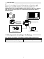
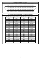
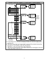
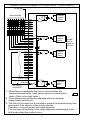
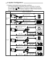
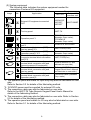
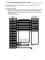
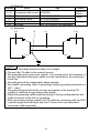
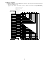
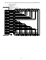
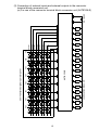
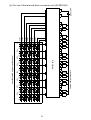
A8GT-50KBF External I/O Interface Module User’s Manual (Hardware) Thank you for choosing the MELSEC-GOT Series. To ensure correct use of this equipment, please read this manual carefully before operating it. MODEL A8GT-50KBF-U MODEL 1DM053 CODE IB(NA)-68908-C(0406)MEE MITSUBISHI Graphic Operation Terminal ! SAFETY PRECAUTIONS ! (Always read before starting use) When using Mitsubishi equipment, thoroughly read this manual and the associated manuals introduced in the manual. Also pay careful attention to safety and handle the module properly. These precautions apply only to the installation of Mitsubishi equipment and the wiring with the external device. Refer to the user’s manual of the CPU module to be used for a description of the PLC system safety precautions. These SAFETY PRECAUTIONS classify the safety precautions into two categories: "DANGER" and "CAUTION". DANGER Procedures which may lead to a dangerous condition and cause death or serious injury if not carried out properly. CAUTION Procedures which may lead to a dangerous condition and cause superficial to medium injury, or physical damage only, if not carried out properly. CAUTION may also Depending on circumstances, procedures indicated by be linked to serious results. In any case, it is important to follow the directions for usage. Store this manual in a safe place so that you can take it out and read it whenever necessary. Always forward it to the end user. [DESIGN PRECAUTIONS] DANGER ! Some faults of the GOT, this unit or connection cables may keep the outputs on or off. An external monitoring circuit should therefore be provided to check for output signals which may lead to a serious accident. Otherwise, mis-output or misoperation can cause an accident. A-1 [INSTALLATION PRECAUTIONS] DANGER ! When installing and removing this module from the GOT main module be sure to shut off the power at all external switches. If all the switches are not turned off, the module could be damaged or malfunction. ! When connecting the bus connection cable to this module be sure to turn off the switch to all external power switches to the GOT and PC CPU. If all the switches are not turned off, it may cause malfunction. CAUTION ! Use this module in an environment that is within the general specifications written in the GOT User's Manual. If the power supply is used in an environment that is outside of the general specifications then electric shock, fire, malfunction, or product damage or degradation could occur. ! For a correct installation, insert the bus connection cable to this module, A7GT-BUS2S, bus connector conversion module, and base unit connector until you hear it click. A bad connection could cause erroneous input or output. ! When installing this module in the GOT main module, install it in the GOT installation area and be sure it is fastened with a module fastening screw that is tightened within the specified torque range. If the module fixing screws are loosen, it may cause malfunction, damage or falling of the module. If the module fixing screws are too tight, the GOT main module or the screws could break. [Wiring Instructions] DANGER ! Before starting wiring, always switch off all phases of the power supply externally. CAUTION ! During wiring, care should be taken so that foreign matter such as shield and wire offcuts do not enter this unit. Otherwise, a fire, fault or misoperation can occur. A-2 [STARTING AND MAINTENANCE PRECAUTIONS] DANGER ! Do not change the switch setting while power is on. ! Switch all phases of the GOT external power supply off before cleaning. Not doing so could result in electric shock. CAUTION ! Never disassemble or modify the module. This may cause breakdowns, malfunctioning, injury, and/or fire. ! Do not directly touch the conducted area and electric parts of this module. It may cause damage and malfunctioning of the module. ! This module is made of resinous materials, and should be protected from strong shock or impact. It may cause breakdown. ! When disconnecting the communication or power cable from the module, do not hold and pull the cable part. When disconnecting the cable having a connector, hold the connector plugged in the module. Before disconnecting the cable having no connector, loosen the screws in the module. If the cable connected to the module is pulled, the module or cable may be damaged or a malfunction may occur due to a cable connection fault. ! Before handling the unit, touch a grounded metal or similar object to discharge the static electricity from the human body. Failure to do so may cause the unit to fail or mulfunction. [DISPOSAL PRECAUTIONS] CAUTION ! When disposing of this product, treat it as industrial waste. A-3 Revisions * The manual number is noted at the lower left of the back cover. Print Date *Manual Number Revision Jun., 1997 IB(NA)-68908-A First printing May, 2001 IB(NA)-68908-B Partial correction Chapter 1, Chapter 3, Chapter 4, Chapter 5, Chapter 7 Jun., 2004 IB(NA)-68908-C Partial correction SAFETY PRECAUTION, Manuals MODEL CODE change Changed from 13JL17 to 1DM053 This manual confers no industrial property rights or any rights of any other kind, nor does it confer any patent licenses. Mitsubishi electric Corporation cannot be held responsible for any problems involving industrial property rights which may occur as a result of using the contents noted in this manual. 1997 MITSUBISHI ELECTRIC CORPORATION A-4 CONTENTS 1. Overview........................................................................................................ 1 2. Components Including in the Package .......................................................... 1 3. Specifications ................................................................................................ 2 4. System configuration ..................................................................................... 7 5. User-fabricasted connection cables............................................................... 9 5.1 Connection cable .................................................................................... 9 5.2 Wiring diagrams .................................................................................... 13 6. Parts Identifcation........................................................................................ 17 7. Installation Procedure .................................................................................. 18 8. Outline Dimension Drawing ......................................................................... 19 Manuals The following manuals are relevant to this product. Refer to the following list and order the required manuals. Relevant Manuals Manual name A8GT-TK type Numeric Keypad Panel User's Manual (Found in the packing of the A8GT-TK) GOT-A900 Series User's Manual (GT Works Version5/GT Designer Version5 compatible connection Sysytem Manual) (Available as option) SW3NIW-A8GOTP Graphic Settings Software Package Operating Manual (Monitor Screen Creation Manual) (Found in the packing of the software package) A-5 Manual No. (Model code) IB-66832 (1DM094) SH-080119 (1DM189) IB-66793 (1DM176) 1. Overview This user's manual gives the specifications, system configurations, parts identifi-cation, installation procedure and outline dimensions of the A8GT50KBF type external I/O unit (referred to as the external I/O unit). The external I/O unit is fitted to the A956WGOT/A95*GOT/A85*GOT (referred to as the GOT) to receive up to 8/64 points of inputs and provide up to 16 points of outputs. GOT Operation panel, pushbutton, numeric keypad panel, etc. External I/O module Connector terminal block conversion unit Lamp, relay, etc. DC power supply 12/24V 2. Components Including in the Package After opening the container, check that the following products are present. Description Quantity External I/O unit 1 External connector (soldered type) 1 1 3. Specifications Input system Number of input points Isolation system Rated input voltage Rated input current Operating voltage range Max. number of simultaneous input points ON voltage/ON current OFF voltage/OFF current Input resistance ON to OFF Response time *1 OFF to ON Dynamic scan cycle Output system Number of output points Isolation system Rated load voltage Max. load current*4 Operating load voltage range Max. inrush current Leakage current at OFF Max. voltage drop at ON ON to OFF Response time*1 OFF to ON Surge suppressor Input Specifications Dynamic scan 8/64 points Photocoupler isolation 12VDC 24DVC Approx. 4mA Approx. 9mA 10.2 to 26.4VDC (ripple percentage within 5%) 100% simultaneous ON (at 26.4VDC) 8VDC or more/2mA or more 4VDC or less/1mA or less Approx. 2.4KΩ Approx. 0.4ms or less (24VDC) Approx. 0.4ms or less (24VDC) 13.3ms Output Specifications Direct 16 points Photocoupler isolation 12/24DVC 0.1A/1 point 10.2 to 26.4VDC (ripple percentage within 5%) 0.4A 0.1mA or less 2.5VDC (0.1A) 2ms or less 2ms or less (resistive load) Clamp diode 2 I/O Specifications External connection system 40-pin connector Applicable wire size 0.3mm2 Operation indicator None 12/24VDC Voltage*3 (10.2 to 26.4V, ripple percentage 5% or less) External supply power 1.65A for external output Current 0.05A for internal consumption only Fuse rating*2 2.0A fuse, unreplaceable Internal current consumption 0.1A Weight 250g(0.55lb) 1 piece of external wiring connector Accessory (soldered type) *1: Time in the I/O section. *2: The maximum load current varies with the number of simultaneous ON points. Refer to the following information: Relationships between output load current (common current), number of simultaneous ON points and ambient temperature 0.1A 16points =1.6A Common current 0.08A 16points =1.28A Ambient temperature 51 55 *3: A fuse-blown error will also be displayed when the external supply power switches off. *4: The fuse in the output unit is provided to prevent the external wiring from burning out if the outputs of the unit are shorted. Therefore, it may not protect the output elements. The fuse may not be blown if the output elements are damaged in the fault mode other than a short circuit. 3 External Connector Pin-Outs View from the unit front Connector used: Fujitsu's FCN-365P040-AU B1 B2 B3 B4 B5 B6 B7 B8 B9 B10B11B12B13B14B15B16B17B18B19B20 A1 A2 A3 A4 A5 A6 A7 A8 A9 A10A11A12A13A14A15A16A17A18A19A20 Pin Numbers and Signal Names of External Connector Pin Number A1 A2 A3 A4 A5 A6 A7 A8 A9 A10 A11 A12 A13 A14 A15 A16 A17 A18 A19 A20 Signal Name XD7 XD5 XD3 XD1 XSCN7 XSCN5 XSCN3 XSCN1 YD15 YD13 YD11 YD9 YD7 YD5 YD3 YD1 DC12/24V DC12/24V 0V Pin Number B1 B2 B3 B4 B5 B6 B7 B8 B9 B10 B11 B12 B13 B14 B15 B16 B17 B18 B19 B20 4 Signal Name XD6 XD4 XD2 XD0 XSCN8 XSCN4 XSCN2 XSCN0 YD14 YD12 YD10 YD8 YD6 YD4 YD2 YD0 DC12/24V 0V FG External Connection Diagram (1) (8-point inputs, 16-point outputs) Pin number L L Internal control circuit R R B4 A4 B3 A3 B2 A2 B1 A1 XD0 XD1 XD2 XD3 XD4 XD5 XD6 XD7 B8 A8 B7 A7 B6 A6 B5 A5 XSCN0 XSCN1 XSCN2 XSCN3 XSCN4 XSCN5 XSCN6 XSCN7 R B16 A16 B15 A15 B14 A14 B13 A13 B12 A12 B11 A11 B10 A10 B9 A9 YD0 YD1 YD2 YD3 YD4 YD5 YD6 YD7 YD8 YD9 YD10 YD11 YD12 YD13 YD14 YD15 R Internal control circuit Internal scan is made at 1/8 duty. Internal control circuit A17,B17,A18 + - Fuse-blown detector circuit B18,A19 DC12/24V (12/24VDC) *1: A fuse-blown error will also be displayed when the external supply power switches off. *2: The fuse in the output unit is provided to prevent the external wiring from burning out if the outputs of the unit are shorted. Therefore, it may not protect the output elements. The fuse may not be blown if the output elements are damaged in the fault mode other than a short circuit. 5 External Connection Diagram (2) (64-point inputs, 16-point outputs) Pin number Input terminals 38 30 28 20 18 10 08 00 39 31 29 21 19 11 09 01 3A 32 2A 22 1A 12 0A 02 3B 33 2B 23 1B 13 0B 03 3C 34 2C 24 1C 14 0C 04 3D 35 2D 25 1D 15 0D 05 3E 36 2E 26 1E 16 0E 06 3F 37 2F 27 1F 17 0F 07 L L Internal control circuit R R B4 A4 B3 A3 B2 A2 B1 A1 XD0 XD1 XD2 XD3 XD4 XD5 XD6 XD7 B8 A8 B7 A7 B6 A6 B5 A5 XSCN0 XSCN1 XSCN2 XSCN3 XSCN4 XSCN5 XSCN6 XSCN7 R B16 A16 B15 A15 B14 A14 B13 A13 B12 A12 B11 A11 B10 A10 B9 A9 YD0 YD1 YD2 YD3 YD4 YD5 YD6 YD7 YD8 YD9 YD10 YD11 YD12 YD13 YD14 YD15 R Internal control circuit Internal scan is made at 1/8 duty. Internal control circuit A17,B17,A18 + - Fuse-blown detector circuit B18,A19 DC12/24V (12/24VDC) *1: When there is a probability that two or more switches are pressed simultaneously, each switch must be provided with a diode. (Refer to the right figure.) *2: A fuse-blown error will also be displayed when the external supply power switches off. *3: The fuse in the output unit is provided to prevent the external wiring from burning out if the outputs of the unit are shorted. Therefore, it may not protect the output elements. The fuse may not be blown if the output elements are damaged in the fault mode other than a short circuit. 6 4. System Configuration (1) System configurations and connection conditions The following system configuration assumes connection of a printer. The numbers ( to ) given in the system configurations denote the numbers ( to ) in "(2) System equipment". Refer to these numbers when you want to confirm the types and applications. Connection Conditions System Configuration Numeric Keypad Panel Connection cable Max. 20m For input only Operation panel Connection cable Max. 20m Connector terminal block conversion unit General-purpose input devices (e.e. pushbuttons) Connection cable Connection cable General-purpose output devices (e.e. pushbuttons) Connection cable Max. 20m Max. 10m Numeric Keypad Panel Connector terminal block conversion unit For I/O Connection cable Connection cable General-purpose output devices (e.e. pushbuttons) Connection cable Max. 20m Max. 10m Operation panel Connector terminal block conversion unit Connection cable Connection cable General-purpose output devices (e.e. pushbuttons) Connection cable Max. 20m Max. 10m 7 (2) System equipment The following table indicates the system equipment needed for connection of external I/O equipment. Image No. Applocation Type External I/O GOT unit interface unit External I/O equipment-connected GOT A956WGOT, A95*GOT, A85*GOT Ten-key panel A8GT-TK Operation panel*1 FP5-MD41-A (Kanaden Corp. make), FP5-MD41-B (Kanaden Corp. make) Connector terminal block conversion unit*2 Connection cable between [GOT] and [ten-key panel]*2*3 Connection cable between [GOT] and [operation panel]*1*2*5 Connection cable between [GOT] and [connector terminal block conversion unit]*2*5 Connection cable between [connector terminal block conversion unit] and [general-purpose I/O equipment] Connection cable between [connector terminal block conversion unit] and [ten-key panel] Connection cable between [connector terminal block conversion unit] and [operation panel]*5 A8GT-50KBF A6TBY36-E, A6TBY54-E A8GT-C05TK(0.5m) Connection cable (Kanaden Corp. make) A8GT-C30TB(3m) (Refer to Section 5.1 and fabricate on user side.) (Refer to A8GT-TK Numeric Keypad Panel User's Manual and fabricate on user side.) Connection cable (Kanaden Corp. make) *1: The operation panel and cable for input only may also be fabricated on user side. Refer to Section 5.2 for details of the fabricating method. *2: 12/24VDC power must be supplied for external I/O units. *3: The connection cable may also be fabricated on user side. Refer to the A8GT-TK Type Numeric Keypad Panel User's Manual for details of the fabricating method. *4: The connection cable may also be fabricated on user side. Refer to Section 5.2 for details of the fabricating method. *5: The operation panel and cables for I/O may also be fabricated on user side. Refer to Section 5.1 for details of the fabricating method. 8 5. User-fabricated Connection Cables The following is the way of fabricating the connection cable which can be fabricated by the user: 5.1 Connection cable (1) Cable for connection between external I/O unit and original operator panel Fabricate the connection cable in accordance with the following wiring diagram, parts diagram and assembly drawing: (Maximum cable length: 20m (16.4feet)) (a) Connection diagram Original operator panel side External I/O unit side Pin number B4 A4 B3 A3 B2 A2 B1 A1 B8 A8 B7 A7 B6 A6 B5 A5 A9 B9 A10 B10 A11 B11 A12 B12 A13 B13 A14 B14 A15 B15 A16 B16 A17 B17 A18 B18 A19 B19 A20 B20 Signal name XD0 XD1 XD2 XD3 XD4 XD5 XD6 XD7 XSCN0 XSCN1 XSCN2 XSCN3 XSCN4 XSCN5 XSCN6 XSCN7 YD15 YD14 YD13 YD12 YD11 YD10 YD9 YD8 YD7 YD6 YD5 YD4 YD3 YD2 YD1 YD0 DC12/24V DC12/24V DC12/24V 0V 0V None None FG Shield Pin number Signal name XD0 XD1 XD2 XD3 XD4 XD5 XD6 XD7 XSCN0 XSCN1 XSCN2 XSCN3 XSCN4 XSCN5 XSCN6 XSCN7 Cables for connection of external input power supply DC12/24V Shieleded cableconnect with FG 9 (b) Parts list Number Name Type Maker Mitsubishi Electric 1) 2) Connector (with cover) A6CON1 1) 2) 3) 4) Connector Connector cover Pair shielded cable FG wire Wires for connection of external input power FCN-361JO40-AU FCN-360CO40-B UL 2464 AWG26 or equivalent UL 1015 AWG14 or equivalent 5) Fujitsu UL 1007 AWG24 or equivalent (c) Assembly 1) 2) DC power supply 12/24V 5) 3) User's desired connector 4) POINT " The cable fabricated should be within 3m in length . " Connect the FG cable to the nearest ground " The grounding wire (green wire, approx. 1m) coming out of the connector of the user-fabricated connection cable must be connected to the control box or the like. " Grounding should be independent where possible. " Use class D grounding (class 3 grounding) method (grounding resistance is 100 Ω max.). " The grounding point should be as near as possible to the external I/O module to minimize the grounding cable length. " Adjust the grounding cable length according to the grounding position and install a terminal or the like for grounding. " When grounding, always connect the FG cable for connection with the GOT ’s power supply terminal block and the FG wire of the user-fabricated connection cable separately. 10 (2) Cable for connection between external I/O unit and terminal block conversion unit. Fabricate the connection cable in accordance with the following wiring diagram, parts diagram and assembly drawing: (Maximum cable length: 10m (32.79feet)). (a) Connection diagram Original operator panel side External I/O unit side Pin number B4 A4 B3 A3 B2 A2 B1 A1 B8 A8 B7 A7 B6 A6 B5 A5 A9 B9 A10 B10 A11 B11 A12 B12 A13 B13 A14 B14 A15 B15 A16 B16 A17 B17 A18 B18 A19 B19 A20 B20 Signal name XD0 XD1 XD2 XD3 XD4 XD5 XD6 XD7 XSCN0 XSCN1 XSCN2 XSCN3 XSCN4 XSCN5 XSCN6 XSCN7 YD0 YD1 YD2 YD3 YD4 YD5 YD6 YD7 YD8 YD9 YD10 YD11 YD12 YD13 YD14 YD15 DC12/24V DC12/24V DC12/24V 0V 0V None None FG Shield Pin number 20B 20A 19B 19A 18B 18A 17B 17A 16B 16A 15B 15A 14B 14A 13B 13A 12B 12A 11B 11A 10B 10A 9B 9A 8B 8A 7B 7A 6B 6A 5B 5A 4B 4A 3B 3A 2B 2A 1B 1A 11 Signal name XD0 XD1 XD2 XD3 XD4 XD5 XD6 XD7 XSCN0 XSCN1 XSCN2 XSCN3 XSCN4 XSCN5 XSCN6 XSCN7 YD0 YD1 YD2 YD3 YD4 YD5 YD6 YD7 YD8 YD9 YD10 YD11 YD12 YD13 YD14 YD15 24V 24V 24V 0V 0V None None None (b) Parts list Number Name 1) 2) 1) 2) 3) 4) Type Connector (with cover) A6CON1 Connector Connector cover Pair shielded cable FG wire FCN-361JO40-AU FCN-360CO40-B UL 2464 AWG26 or equivalent UL 1015 AWG14 or equivalent Maker Mitsubishi Electric Fujitsu (c) Assembly 1) 2) 4) 3) 1) 2) POINT " The cable fabricated should be within 3m in length . " Connect the FG cable to the nearest ground " The grounding wire (green wire, approx. 1m) coming out of the connector of the user-fabricated connection cable must be connected to the control box or the like. " Grounding should be independent where possible. " Use class D grounding (class 3 grounding) method (grounding resistance is 100 Ω max.). " The grounding point should be as near as possible to the external I/O module to minimize the grounding cable length. " Adjust the grounding cable length according to the grounding position and install a terminal or the like for grounding. " When grounding, always connect the FG cable for connection with the GOT ’s power supply terminal block and the FG wire of the user-fabricated connection cable separately. 12 5.2 Wring diagrams (1) Wiring diagram for use between external I/O unit and connector terminal block conversion unit (a) For use of the connector terminal block conversion unit (A6TBY36-E) Cable for connection between external I/O unit and connector terminal block A8GT-70KBF conversion unit 0 Shield B4 XD0 A4 XD1 B3 XD2 A3 XD3 B2 XD4 A2 XD5 B1 XD6 A1 XD7 B8 XSCN0 A8 XSCN1 B7 XSCN2 A7 XSCN3 B6 XSCN4 A6 XSCN5 B5 XSCN6 A5 XSCN7 A9 YD0 B9 YD1 A10 YD2 B10 YD3 A11 YD4 B11 YD5 A12 YD6 B12 YD7 A13 YD8 B13 YD9 A14 YD10 B14 YD11 A15 YD12 B15 YD13 A16 YD14 B16 YD15 A17 DC12/24V B17 DC12/24V A18 DC12/24V 0V B18 0V A19 B19 Empty A20 Empty FG B20 2 4 1 B20 A20 B19 A19 B18 A18 B17 A17 B16 A16 B15 A15 B14 A14 B13 A13 B12 A12 B11 A11 B10 A10 B9 A9 B8 A8 B7 A7 B6 A6 B5 A5 B4 A4 B3 A3 B2 A2 B1 A1 3 6 5 8 7 A 9 C E B D 24V F 0V A6TBY36-E 10 12 11 14 13 13 16 15 18 17 1A 19 1C 1B 1E 1D 24V 1F 0V (b) For use of the connection terminal block conversion unit (A6TBY54-E) Cable for connection between external I/O unit and connection terminal block A8GT-70KBF conversion unit 0 -C Shield 1 -C B4 XD0 A4 XD1 B3 XD2 A3 XD3 B2 XD4 A2 XD5 B1 XD6 A1 XD7 B8 XSCN0 A8 XSCN1 B7 XSCN2 A7 XSCN3 B6 XSCN4 A6 XSCN5 B5 XSCN6 A5 XSCN7 A9 YD0 B9 YD1 A10 YD2 B10 YD3 A11 YD4 B11 YD5 A12 YD6 B12 YD7 A13 YD8 B13 YD9 A14 YD10 B14 YD11 A15 YD12 B15 YD13 A16 YD14 B16 YD15 A17 DC12/24V B17 DC12/24V A18 DC12/24V 0V B18 0V A19 B19 Empty A20 Empty FG B20 2 4 3 -C 5 6 -C B20 A20 B19 A19 B18 A18 B17 A17 B16 A16 B15 A15 B14 A14 B13 A13 B12 A12 B11 A11 B10 A10 B9 A9 B8 A8 B7 A7 B6 A6 B5 A5 B4 A4 B3 A3 B2 A2 B1 A1 8 7 -C 9 A -C C B -C D E -C -C F 0V 24V A6TBY54-E 10 -C 11 12 -C 14 13 -C 15 14 16 -C 18 17 -C 19 1A -C 1C 1B -C 1D 1E -C -C 1F 0V 24V 00 08 10 18 20 15 Load Load Load Load Load Load Load Load Loads:Lamps,relays,etc. 1F 1E E 1D D 1C C 1B B 1A A 19 9 18 8 XSCN0 XSCN1 XSCN2 XSCN3 XSCN4 XSCN5 XSCN6 XSCN7 Load 17 7 XD7 Load 16 6 07 0F 17 1F 27 2F 37 XD6 3F Load 15 5 06 0E 16 1E 26 2E 36 XD5 3E Load 14 A6TBY36-E 4 05 0D 15 1D 25 2D 35 XD4 3D Load 13 3 0C 0C 14 1C 24 2C 34 XD3 3C Load 12 2 03 0B 13 1B 23 2B 33 XD2 3B Load 11 1 02 0A 12 1A 22 2A 32 XD1 3A Load 10 0 01 09 11 19 21 29 31 30 28 XD0 39 38 User-fabricated original operator panel F 0V DC12/24V 24V (2) Connection of external inputs and external outputs to the connector terminal block conversion unit. (a) For use of the connector terminal block conversion unit (A6TBY36-E) 00 08 10 18 20 16 A B 1D -C -C 1E -C -C 1C 9 1B 8 7 6 19 -C -C 1A -C -C XSCN0 XSCN1 XSCN2 XSCN3 XSCN4 XSCN5 XSCN6 XSCN7 18 5 07 0F 17 1F 27 XD7 17 A6TBY54-E 4 06 0E 16 1E 26 2F 37 XD6 3F Load Load 15 -C -C 16 3 05 0D 15 1D 25 2E 36 XD5 3E Load Load 14 2 0C 0C 14 1C 24 2D 35 34 2C XD4 3D XD3 3C Load Load 13 -C -C 03 0B 13 1B 23 2B 33 XD2 3B Load Load 11 -C -C 12 1 02 0A 12 1A 22 2A 32 XD1 3A Load Load 10 0 01 09 11 19 21 29 31 30 28 XD0 39 38 User-fabricated original operator panel Load Load Load Loads:Lamps,relays,etc. D 1F -C C -C -C F 0V -C DC12/24V 24V E (b) For use of the terminal block conversion unit (A6TBY54-E) Load Load Load 6. Pates Identification 2) 1) A8GT-50KBF 4) 2) 3) No. 2) Name I/O cable connection interface Unit fixing screws 3) Connector 4) Rating plate 1) Description Interface for connection of the I/O cable Screws used to fix the unit to the GOT Connector used to plug the unit to the GOT. 17 7. Installation Procedure Install the unit to the GOT in the following procedure: (1) Thread External I/O unit mounting screw holes in the control box or the like. (2-φ3.5 mounting holes) The External I/O unit’s GOT connection cable is 50cm long. Install the External I/O unit within this distance so that the GOT-end connector of the cable may be fitted into the GOT’s connector. When mounting the External I/O unit on the back of control box door, exercise care to avoid screw holes passing through the control box surface. (2) Tighten the mounting screws to the specified torque range 39 to 59N.cm. (3) Plug the GOT side connector of the External I/O unit to the option unit of the GOT. To remove the unit, reverse the installation procedure. 18 8. Outline Dimension Drawing 65 (2.56) 73 (2.87) A8GT-50KBF 92 (3.62) 9.5 (0.37) 105 (4.13) 44 (1.73) 500 (19.69) 42.6 (1.68) 67.8 (2.67) 3.2 (0.13) 3.5 (0.14) MITSUBISHI Unit: mm (inch) 19 20 21 Warranty Mitsubishi will not be held liable for damage caused by factors found not to be the cause of Mitsubishi; machine damage or lost profits caused by faults in the Mitsubishi products; damage, secondary damage, accident compensation caused by special factors unpredictable by Mitsubishi; damages to products other than Mitsubishi products; and to other duties. For safe use " This product has been manufactured as a general-purpose part for general industries, and has not been designed or manufactured to be incorporated in a device or system used in purposes related to human life. " Before using the product for special purposes such as nuclear power, electric power, aerospace, medicine or passenger movement vehicles, consult with Mitsubishi. " This product has been manufactured under strict quality control. However, when installing the product where major accidents or losses could occur if the product fails, install appropriate backup or failsafe functions in the system. Country/Region Sales office/Tel U.S.A Mitsubishi Electric Automation Inc. 500 Corporate Woods Parkway Vernon Hills, IL 60061 Tel : +1-847-478-2100 Brazil MELCO-TEC Rep. Com.e Assessoria Tecnica Ltda. AV. Paulista 1471, Conj. 308, Sao Paulo City, Sao Paulo State, Brazil Tel : +55-11-283-2423 Germany Mitsubishi Electric Europe B.V. German Branch Gothaer Strasse 8 D-40880 Ratingen, GERMANY Tel : +49-2102-486-0 U.K Mitsubishi Electric Europe B.V. UK Branch Travellers Lane, Hatfield, Herts., AL10 8XB,UK Tel : +44-1707-276100 Italy Mitsubishi Electric Europe B.V. Italian Branch Centro Dir. Colleoni, Pal. Perseo-Ingr.2 Via Paracelso 12, 20041 Agrate B., Milano, Italy Tel : +39-039-6053344 Spain Mitsubishi Electric Europe B.V. Spanish Branch Carretera de Rubi 76-80 08190 - Sant Cugat del Valles, Barcelona, Spain Tel : +34-93-565-3131 France Mitsubishi Electric Europe B.V. French Branch 25 Boulevard des Bouvets, F-92741 Nanterre Cedex, France TEL: +33-1-5568-5568 South Africa Circuit Breaker Industries LTD. Tripswitch Drive, Elandsfontein Gauteng, South Africa Tel : +27-11-928-2000 Country/Region Sales office/Tel Hong Kong Ryoden Automation Ltd. 10th Floor, Manulife Tower, 169 Electric Road, North Point, HongKong Tel : +852-2887-8870 China Ryoden Automation Shanghai Ltd. 3F Block5 Building Automation Instrumentation Plaza 103 Cao Bao Rd. Shanghai 200233 China Tel : +86-21-6475-3228 Taiwan Setsuyo Enterprise Co., Ltd. 6F., No.105 Wu-Kung 3rd.RD, Wu-Ku Hsiang, Taipei Hsine, Taiwan Tel : +886-2-2299-2499 Korea HAN NEUNG TECHNO CO.,LTD. 1F Dong Seo Game Channel Bldg., 660-11, Deungchon-dong Kangsec-ku, Seoul, Korea Tel : +82-2-3660-9552 Singapore Mitsubishi Electric Asia Pte, Ltd. 307 ALEXANDRA ROAD #05-01/02, MITSUBISHI ELECTRIC BUILDING SINGAPORE 159943 Tel : +65-6473-2308 Thailand F. A. Tech Co.,Ltd. 898/28,29,30 S.V.City Building,Office Tower 2,Floor 17-18 Rama 3 Road, Bangkpongpang, Yannawa, Bangkok 10120 Tel : +66-2-682-6522 Indonesia P.T. Autoteknindo SUMBER MAKMUR Jl. Muara Karang Selatan Block A Utara No.1 Kav. No.11 Kawasan Industri/ Pergudangan Jakarta - Utara 14440 Tel : +62-21-663-0833 India Messung Systems Put,Ltd. Electronic Sadan NO:111 Unit No15, M.I.D.C BHOSARI,PUNE-411026 Tel : +91-20-712-2807 Australia Mitsubishi Electric Australia Pty. Ltd. 348 Victoria Road, PostalBag, No 2, Rydalmere, N.S.W 2116, Australia Tel : +61-2-9684-7777 HEAD OFFICE : 1-8-12, OFFICE TOWER Z 14F HARUMI CHUO-KU 104-6212, JAPAN NAGOYA WORKS : 1-14, YADA-MINAMI 5-CHOME, HIGASHI-KU, NAGOYA, JAPAN When exported from Japan, this manual does not require application to the Ministry of Economy, Trade and Industry for service transaction permission. Specifications subject to change without notice. Printed in Japan on recycled paper.