1
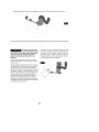
Owner's Manual
I CRRFTSMRN°I
ALL-IN-ONE
CUTTING TOOL
Model Nos.
170.172440
170.172450
170.265610
Caution:
Before using this product,
read this manual and follow
all its Safety Rules and
Operating Instructions.
•
•
Safety
Operation
Maintenance
Parts
Espahol,
(page 9)
Sears, Roebuck and Co., Hoffman Estates, IL 60179 U.S.A.
Page
Warranty .....................................................
Power Tool Safety Rules
Symbols
3-5
.....................................................
Functional Description and Specifications
Assembly
6
.........................
.................................................
Operating Instructions
.......................................
Maintenance
..............................................
Accessories
.................................................
Espa_ol
2
......................................
..................................................
7-8
9-12
13-16
16-17
18
19-35
FULL ONE YEAR WARRANTY ON CRAFTSMAN
ALL-IN-ONE CUTTING TOOL
If this CRAFTSMAN All-In-One Cutting Tool fails to give complete
satisfaction within one year from the date of purchase, RETURN IT TO
THE NEAREST SEARS STORE OR OTHER CRAFTSMAN OUTLET IN
THE UNITED STATES, and Sears will replace it, free of charge.
If this CRAFTSMAN AlPln-One Cutting Tool is used for commercial or
rental purposes, this warranty applies for only 90 days from the date of
purchase.
This warranty gives you specific legal rights, and you may also have other
rights which vary from state to state.
Sears, Roebuck and Co., Dept. 817WA, Hoffman Estates, IL 60179
-2-
Read and understand all instructions.
Failure to follow all instructions
listed below, may result in electric shock, fire and/or serious personal injury.
SAVE THESE
Work Area
Keep your work area clean and well lit.
Cluttered
benches
and dark areas invite
accidents.
Do not operate power tools in explosive
atmospheres, such as in the presence of
flammable liquids, gases, or dust. Power
tools create sparks which may ignite the dust
or fumes.
INSTRUCTIONS
When operating a power tool outside, use
an outdoor extension cord marked "W-A"
or "W." These cords are rated for outdoor use
and reduce the risk of electric shock. Refer to
"Recommended
sizes of Extension Cords" in
the Accessory section of this manual.
Personal
Safety
Stay alert, watch what you are doing and
use common
sense
when operating
a
power tool. Do not use tool while tired or
under the influence of drugs, alcohol, or
medication.
A moment of inattention
while
operating
power tools may result in serious
personal injury.
Keep by-standers, children, and visitors
away while operating
a power tool.
Distractions can cause you to lose control.
Electrical Safety
Double Insulated tools are equipped with
a polarized plug (one blade is wider than
the other.) This plug will fit in a polarized
outlet only one way.
If the plug does not
fit fully in the outlet, reverse the plug. If it
still does
not fit, contact
a qualified
electrician to install a polarized outlet. Do
not change the plug in any way. Double
Insulation _]eliminates
the need for the three
wire grounded
power cord and grounded
power supply system. Before plugging in the
tool, be certain the outlet voltage supplied is
within the voltage marked on the nameplate.
Do not use "AC only" rated tools with a DC
power supply.
Avoid
body
contact
with
grounded
surfaces such as pipes, radiators, ranges
and refrigerators. There is an increased risk
of electric shock if your body is grounded. If
operating the power tool in damp locations is
unavoidable, a Ground Fault Circuit Interrupter
must be used to supply the power to your tool.
Electrician's
rubber gloves and footwear will
further enhance your personal safety.
Dress properly.
Do not wear loose clothing
or jewelry.
Contain
long hair. Keep your
hair, clothing,
and gloves
away
from
moving parts. Loose clothes, jewelry, or long
hair can be caught in moving parts. Keep
handles
dry, clean and free from oil and
grease.
Avoid accidental
starting. Be sure switch is
"OFF" before plugging
in. Carrying tools with
your finger on the switch or plugging in tools
that have the switch "ON" invites accidents.
Remove adjusting keys or wrenches
before
turning the tool "ON". A wrench or a key that
is left attached to a rotating part of the tool may
result in personal injury.
Do not overreach.
Keep proper footing and
balance
at all times.
Proper footing
and
balance enables better control of the tool in
unexpected
situations.
Use safety equipment.
Always
wear eye
protection.
Dust mask, non-skid safety shoes,
hard hat, or hearing protection must be used
for appropriate conditions.
Don't expose
power tools to rain or wet
conditions.
Water entering a power tool will
increase the risk of electric shock.
Tool Use and Care
use clamps or other practical way to
secure and support the workpiece to a
stable platform. Holding the work by hand or
against your body is unstable and may lead to
loss of control.
Do not abuse the cord. Never use the cord
to carry the tools or pull the plug from an
outlet. Keep cord away from heat, oil, sharp
edges or moving parts. Replace damaged
cords immediately. Damaged cords increase
the risk of electric shock.
Do not force tool. Use the correct tool for
your application.
-3-
The correct tool will do the
job better and safer at the rate for which it is
designed.
serviced before using. Many accidents are
caused by poorly maintained tools. Develop a
periodic maintenance schedule for your tool.
Do not use tool if switch does not turn it
"ON" or "OFF". Any tool that cannot be
controlled with the switch is dangerous and
must be repaired.
Use only accessories
that are recommended by the manufacturer for your
model. Accessories that may be suitable for
one tool, may become hazardous when used
on another tool.
Disconnect the plug from the power source
before making any adjustments, changing
accessories, or storing the tool. Such
preventive safety measures reduce the risk of
starting the tool accidentally.
Service
Tool service must be performed only by
qualified repair personnel. Service or
maintenance performed by unqualified
personnel could result in a risk of injury. For
example: internal wires may be misplaced or
pinched, safety guard return springs may be
improperly mounted.
Store idle tools out of reach of children and
other untrained persons. Tools are
dangerous in the hands of untrained users.
Maintain tools with care. Keep cutting tools
sharp and clean. Properly maintained tools,
with sharp cutting edges are less likely to bind
and are easier to control. Any alteration or
modification is a misuse and may result in a
dangerous condition.
When servicing a tool, use only identical
replacement parts. Follow instructions
in
the Maintenance section of this manual.
Use of unauthorized parts or failure to follow
Maintenance Instructions may create a risk of
electric shock or injury. Certain cleaning
agents such as gasoline, carbon tetrachloride,
ammonia, etc. may damage plastic parts.
Check for misalignment or binding of
moving parts, breakage of parts, and any
other condition that may affect the tools
operation. If damaged, have the tool
Never lay workpiece on top of hard
surfaces, like concrete, stone, etc...
Protruding cutting bit may cause tool to jump.
Hold tool by insulated gripping surfaces
when performing an operation where the
cutting tool may contact hidden wiring or
its own cord. Contact with a "live" wire will
make exposed metal parts of the tool "live"
and shock the operator. If cutting into existing
walls or other blind areas where electrical
Always wear safety goggles and dust
mask. Use only in well ventilated area.
Using personal safety devices and working in
safe environment reduces risk of injury.
wiring may exist is unavoidable, disconnect
all fuses or circuit breakers feeding this
worksite.
After changing the bits or making any
adjustments, make sure the collet nut and
any other adjustment devices are
securely tightened. Loose adjustment
device can unexpectedly shift, causing loss
of control, loose rotating components will be
violently thrown.
Never start the tool when the bit is
engaged in the material. The bit cutting
edge may grab the material causing loss of
control of the cutter.
Always make sure the work surface is free
from nails and other foreign objects.
Cutting into a nail can cause the bit and the
tool to jump and damage the bit.
Never hold the workpiece
in one hand and
the tool in the other hand when in use.
Never place hands near or below cutting
surface. Clamping the material and guiding
the tool with both hands is safer.
-4-
Never lay the tool down until the motor
has come to a complete standstill. The
spinning bit can grab the surface and pull the
tool out of your control.
Always hold the tool with two hands
during start-up. The reaction torque of the
motor can cause the tool to twist.
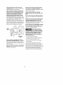
When routing or cutting, the direction of
feed with the bit's cutting edge into the
material is very important, Always feed
the bit into the material in the same
Never use bits that have a cutting
diameter greater than the opening in the
base.
direction as the cutting edge is exiting
from the material. When viewing the tool
from the top, the bit rotates clockwise. If the
tool is between the workpiece and your body,
then feed the tool to your right. If the
workpiece is between the tool and your body,
then feed the tool to your left. Feeding the
tool in the wrong direction causes the cutting
edge of the bit to climb out of the work and
pull the tool in the direction of this feed.
Do not use the tool for drilling purposes.
This tool is not intended to be used with drill
bits.
Always use the tool with the depth guide
securely attached and positioned flat
against material being cut. The guide
securely positioned on the material improves
the stability and control of your tool.
Do not use the cut-off attachment without
the hard auxiliary control handle. The soft
band handle does not provide a sufficient
control for grinding operation.
s,,.,_
_Some
created
by
power dust
sanding,
sawing,
grinding, drilling, and other construction
activities contains chemicals known to
cause cancer, birth defects or other
reproductive harm. Some examples of
these chemicals are:
DIRECTIONOF
FEED
• Lead from lead-based
paints,
• Crystalline silica from bricks and cement
and other masonry products, and
Never use dull or damaged bits. Sharp
bits must be handled with care. Damaged
bits can snap during use. Dull bits require
more force to push the tool, possibly causing
the bit to break.
• Arsenic and chromium
treated lumber.
Your risk from these exposures varies,
depending on how often you do this type of
work. To reduce your exposure to these
chemicals: work in a well ventilated area, and
work with approved safety equipment, such
as those dust masks that are specially
designed to filter out microscopic particles,
Never touch the bit during or immediately
after use. After use the bit is too hot to be
touched
from chemically-
by bare hands.
-5-
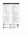
IMPORTANT:
Some of the following symbols
and learn their meaning.
Proper interpretation
tool better and safer.
may be used on your tool. Please study them
of these symbols will allow you to operate the
Symbol
Name
Designation/Explanation
V
Volts
Voltage
A
Amperes
Current
Hz
Hertz
Frequency
W
Watt
Power
(potential)
(cycles per second)
kg
Kilograms
Weight
min
Minutes
Ti me
s
Seconds
Time
Diameter
Size of drill bits, grinding
no
Rotational
No load speed
.../min
Revolutions
or reciprocation
per minute
wheels,
etc.
speed, at no load
Revolutions,
strokes, surface
speed,
orbits etc. per minute
0
1, 2, 3 ....
Off position
Zero speed, zero torque...
Selector settings
Speed, torque
I, II, III,
Higher number
Infinitely variable
selector with off
Arrow
•"X.,
Alternating
--_
or position settings.
means greater speed
Speed is increasing
from 0 setting
Action in the direction of arrow
current
Type or a characteristic
of current
Direct current
Type or a characteristic
of current
Alternating
Type or a characteristic
of current
or direct current
[]
Class II construction
Designates Double Insulated
Construction tools.
(_)
Earthing terminal
Grounding
Warning symbol
Alerts user to warning
Ni-Cad RBRC seal
Designates
program
This symbol designates
that this tool is listed by
Underwriters Laboratories.
terminal
Ni-Cad battery recycling
that this tool is listed to
This symbolStandards
Canadian
designatesby
Underwriters Laboratories.
C@
This symbol designates
that this tool is listed by
the
Standards
This Canadian
symbol designates
Association.
Q
that
Underwriters Laboratories,
U_ this
and tool
listedis to
listed
Canadian
by
Standards by Underwriters
Laboratories.
-6-
messages
•
W
This symbol
designates
that
this tool
complies
to NOM
Mexican
Standards.
Ir'_W
LV,_l:t;tfl
R[_
measures
reduce
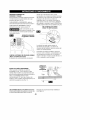
Disconnect the plug from the power source before making any
assembly, adjustments or changing accessories, Such preventive safety
the
risk
of starting
the tool
accidentally,
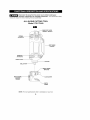
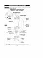
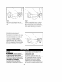
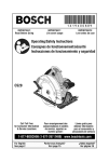
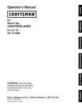
ALL-IN-ONE CUTTING TOOL
Models 170.172450 & 170.265610
SPEED
CONTROL
DIAL
(Model 170.265610 only)
BUMP-OFF
SLIDE
"ON/OFF" SWITCH
HANDLE
BUTTON
COVER
INTAKE
AIR VENTS
REMOVABLE
HARD
JXILIARY
CONTROL
HANDLE
W
EXHAUST.
AIR VENTS
SHAFT
LOCK
COLLAR
WORKLIGHT
(Model 170.265610
KEYLESS
WORKLIGHT
(Model 170.265610
only)
CHUCK
t
t
t
t
only)
DEPTH GUIDE
BRACKET
_
J
LOCKING
SCREW
_
DEPTH GUIDE
LOCK
LEVER
-__".
DEPTH
GUIDE
NOTE:
For tool
specifications
refer
"7"
to nameplate
on your
tool.
_
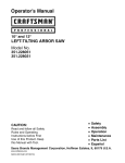
measures
Disconnectadjustments
the plug from
power accessories.
source before Such
making
any
assembly,
or the
changing
preventive
safety
reduce
the risk
of starting
the tool
accidentally.
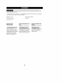
ALL-IN-ONE
CUTTING TOOL
Model 170.172440
W
BUMP-OFF
SLIDE
"ON/OFF"
SWITCH
INTAKE
__
AIR VENTS
SOFTBAND
HANDLE
EXHAUST.
AIR VENTS
SHAFT
LOCK
COLLAR
COLLETNUT
I
I
I
I
_
I
J
DEPTH
GUIDE
BRACKET
DEPTH GUIDE
LOCKING
SCREW
-_-LOCK
LEVER
DEPTH
GUIDE
NOTE:
For tool
specifications
refer
-8-
to nameplate
on your
tool.
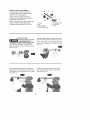
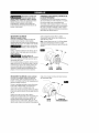
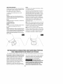
REMOVING
AND INSTALLING
DEPTH GUIDE ASSEMBLY
_
Disconnect
the plug
from
the
power source
before
making any assembly, adjustments or
changing accessories. Such preventive
safety measures reduce the risk of starting
the tool accidentally. Make certain that the
collet nut is securely tightened before turning
the tool on.
THE
The depth guide assembly consists of the
depth guide, locking screw and bracket.
In order to remove the depth guide from the
tool, release the locking lever and pull the
entire assembly straight off of the tool. To
reattach the assembly, fully replace the guide
onto the tool collar and lock the clamp lever
(Fig. 1).
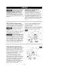
INSTALLING
BITS (Keyless
models)
The bits are held by a keyless collet system
designed specifically for cut-out bits with 1/8"
(.125"), 1/4" (.250") or 5/32" (.156") shanks.
shank exposed) Re-engage the shaft-lock
and securely tighten the keyless chuck
(clockwise) by hand.
Note: When using 1/4" & 5/32" bits it may be
necessary to use a wrench on the front of the
keyless chuck to securely tighten the bit.
The
flutes
are sharp
shouldbit be
handled
with and
caution.
Ir_
Depress and hold the shaft-lock in and rotate
the keyless chuck and shaft until the shaftlock engages and holds the shaft.
1/8"--_.
To prevent damage to tool.
Never use the shaft lock as a
braking
devise to stop the tool from rotating.
Rotate the keyless chuck (counter-clockwise)
(Fig. 3). Remove the old bit (if there is one)
insert the new bit as far in as possible, but
not so far that the bit flutes engage the jaws
of the chuck (leave approximately
1/8" of
SHAFT
LOCK
KEYLESS
CHUCK
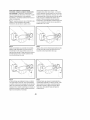
INSTALLING
BITS (Standard
models)
The bits are held by a collet system. Use either
the 1/8" (.125"), 1/4" (.250") or 5/32" (.156")
collet depending on the size of the bit shank.
II=[_lLq
Depress and hold the shaft-lock in and rotate
the collet nut and shaft until the shaft-lock
engages and holds the shaft.
Use the standard equipment wrench to
loosen nut (counter-clockwise)
(Fig. 4).
Remove the old bit (if there is one) insert the
new bit as far in as possible, but not so far
that the bit flutes engage the collet (leave
approximately
1/8" of shank exposed)
Re-engage the shaft-lock and tighten the nut
(clockwise) by hand and then with the
wrench until bit is held securely.
SHAFT
LOCK
-9-
COLLET
NUT
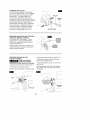
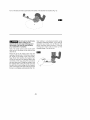
CHANGING
THE COLLET
The 1/8" collet is used with 1/8" diameter
bits, the 1/4" collet is used with 1/4" diameter
bits and the 5/32" collet is used with 5/32"
COLLET
diameter bits. To change collets, first
remove the bit. Continue to loosen and
unscrew the collet nut until you can remove it
from the tool. Remove the collet and replace
it with the other (Fig. 5). (Each collet is
double-ended,
and either end is acceptable
to use.) By hand, re-tighten the collet nut
around the collet in a clockwise direction.
You are now ready to insert a new bit as
instructed in Installing Bits (Fig. 3 or 4).
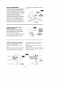
REMOVING AND INSTALLING
THE HARD
AUXILIARY CONTROL
HANDLE
Turn the tool OFF and unplug it. Firmly
grasp the tool. Lift open handle release
button cover, depress release button and
remove handle (Fig. 6).
OUTPUT
\
\
HANDLE
RELEASE
BUTTON
COVER
HANDLE
Gently engage the two (2) front latches on
handle into the tool and push handle until it
snaps securely into place.
REMOVING AND INSTALLING
THE SOFT HANDLE)
SHAFT
BUTTON
handle strap straight away from tool (Fig. 7).
_
Always
use maximum
auxiliary
handle for
control over torque reaction or kick-back.
1 Depress and hold top clip release (Fig, 7).
2 Pull strap away from tool (Fig, 7).
While top clip hook release is depressed, pull
3 Squeeze from each side and hold both
bottom clip releases (Fig. 8).
4 Lift the back of the clip up and away from
tool (Fig. 8).
While depressing both bottom clip release
tabs, lift the back of the clip away from the
tool (Fig.8).
I I1[_:!
CLIP
IP
-10-
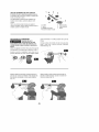
CIRCLE CUTTER ATTACHMENT
The circle cutter is ideal for small do-ityourself projects such as cutting
ceiling tiles for installing lights,
holes in
Please read the following instructions
carefully on how to install and operate the
Circle Cutter Attachment
Kit.
NOTE: Pivot point comes with a rubber boot
attached. Remove rubber boot before
installing and operating the Circle Cutter.
ATTACH TO TOOL
_Make
sure thebefore
cutting tool
is unplugged
attempting to attach it to the circle cutter
and before installing or changing bits.
Slide the adapter into the tool base guide as
shown (Fig. 9).
1 Screw
2 Nut
5 Threaded Knob
6 Pivot Point
3 Base adapter
4 Circle Cutter Arm
7 Knob
Snap the adapter down into place so the tab is
secured into the small hole on the base guide.
Place circle cutter arm onto base guide and
secure with threaded knob. Tighten securely
(Fig, 10),
I1=[_]
Loosen the base guide knob and adjust the
guide height so the bit extends 1/8" more than
the thickness of the material to be cut, Tighten
knob (Fig, 11),
Loosen the knob and slide the pivot point to
the desired hole size marked on the side of
cutter arm (Fig. 12).
-11-
Turn on the tool and make a pilot hole at the center of the desired
I_i_1
Do not use too much force
when cutting. It can
shorten bit life and cause breakage and
the portion of bit may fly away striking
you, bystanders or property.
Note: The center point on the Circle Cutter
pivot foot is at the center of the circle you are
about to cuL
hole location (Fig. 13).
Start cutting in a clockwise
direction
using
consistent moderate pressure. If you need to
reposition
your hands, turn off the tool first
before changing
hand positions.
Continue
cutting your circle until you have cut the
complete shape. Turn off the tool.
Place the tip of the center
point near the
opening of the pilot hole. Tilt the tool at about a
45 ° angle on the edge of the circle cutter.
Keep the bit from touching the material. Turn
on the tool and set to the desired speed. With
one hand on the tool, grasp the round knob
with your other hand. Plunge the cutting bit into
the material while pushing the center point into
the pilot hole. As you plunge into the material,
pivot on the edge of the circle cutter and tip the
tool up to a completely vertical position (Fig. 14).
-12-
\
BUMP-OFF SLIDE "ON/OFF"
SWITCH
This tool is switched "ON" by the slide switch
located on the front of the motor housing
(Fig. 15).
TO TURN THE TOOL "ON" slide the switch
and material hardness for improved finish,
extended bit life, and higher performance.
Speed changes are achieved by rotating
Control Dial RIGHT to increase speed, LEFT
to decrease as indicated on housing (Fig. 16).
button up.
VARIABLE SPEED CONTROL DIAL
(Model 170.265610 only)
TO TURN THE TOOL "OFF" slide the switch
button down or "0" position.
Hold the tool with both
hands while starting, since
torque from the motor can cause the tool to
twist.
_[_
BUMP-OFF
SLIDE
SWITCH
Speed may be changed while tool is on. The
reference numbers on the dial facilitate
re-setting control to desired speed.
ELECTRONIC VARIABLE SPEED
CONTROL (Model 170.265610 only)
The electronic speed control feature allows
motor speed to be matched to cutter size
For best results, when using cut-out bits, we
recommend only using dial setting 25 or 30.
You will not obtain a quality cut if you lower
the dial setting to 15 or 20.
DEPTH GUIDE
LOCKING
SCREW
DEPTH GUIDE ADJUSTMENT
Use the depth guide to adjust the depth of
L__
cut. Using the end of the standard wrench,
loosen (counter clockwise) the screw enough
to enable the depth guide to slide up or down
to the desired depth of cut (about 1/8"
greater than material thickness) and
retighten the locking screw (clockwise)
(Fig. 17).
WORKLIGHT
(Model
170.265610
only)
Your tool is also equipped with a light that
turns on automatically when the switch is
activated for better visibility when cutting
(Fig. 1).
-13-
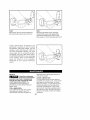
MAKE A FEW PRACTICE
After installing
the cut-out
CUTS
Step 5
After completing your cut, turn off the tool
and carefully remove it from the material.
bit into the tool and
adjusting your depth guide, you should make
a few practice cuts with the tool before
attempting an actual job.
Do not attempt to use this tool to make cutouts around any fixture or opening which has
live electrical wires, or any wall which may
have live electrical wiring behind it, as the bit
could conduct current to the tool, creating an
electrocution hazard for the operator. Shut
off breakers or remove fuses to disconnect
A few exercises will give you the necessary
practice to make clean, professional cuts.
Step 1
Make certain that the collet nut / keyless
chuck is securely tightened before turning
the tool on.
Step 2
Hold the tool firmly and turn the tool ON to
your desired
IMPORTANT
the circuit. Always hold the tool by its
thermoplastic
housing, and always wear eye
protection when operating a cutting tool.
NOTE: Because of the rotating cutting
action of the bit, there will be a slight pull
when cutting. The slower you cut, the more
control you have. Excessive pressure or fast
cutting will cause excessive heat and may
shorten the life of the bit.
speed.
USER TIP
Step 3
While holding the tool firmly, insert the bit
into the material at a 45 + angle (Fig. 18).
Step 4
Slowly bring it to a 90 + angle to begin the cut
(Fig. 19). The base guide should be flush to
the material surface. For all materials
(EXCEPT cutting around outlet boxes in
drywall), steer the tool in a clockwise
direction with slow, steady pressure to make
the cut.
NOTE: When cutting on a vertical surface,
avoid ending your cut at the bottom of the
hole. If possible, start and end your cut at
the top so the scrap part will not drop onto
the rotating bit. Turn the tool off and remove
it from the material.
i[_iI:]
Ii[_IH']
\
ILLUSTRATED
INSTRUCTIONS
OPENINGS IN DRYWALL
The following
MAKING
procedure
DRYWALL
will illustrate
FOR PERFECT
cutting out a standard
CUT OUTS
After assembling the bit into the tool as
described earlier, it will be necessary to
review the instructions provided below and
make some practice cut-outs with this tool
before attempting an actual job. The best
method is to take some scrap pieces and nail
or screw them in place over wall studs which
OUTLET
2 1/8" X 3 3/4" electrical
have an electrical
box.
box or other feature
in
place. A few such exercises will give you the
necessary practice to make clean,
professional cutouts around whatever is
behind the drywall you are installing.
Do
attemptcut-outs
to use this
tool not
to make
around
-14-
any fixture or opening
which
has
and all wires or other obstructions
live electrical wires, or on any wall which
may have live electrical wiring behind it,
as the bit could conduct current to the
around
the
opening are pushed back out of the way. The
drywall cut-out bit uses the outer edge of the
box or fixture as a guide, so it is important
that there is nothing in the way which can
prevent it from guiding completely around the
opening. For the purposes of this instruction
manual, the procedure discussed will be to
make a cut-out around a standard 2 1/8" x 3
3/4" electrical box.
tool, creating an electrocution
hazard for
the operator. Shut off breakers or remove
fuses to disconnect the circuit. Always hold
the tool by its thermoplastic
housing, and
always wear eye protection when operating
this device.
Step 1 : Be certain that the box or fixture
which requires a cut-out is firmly mounted
Step 2
Slide switch to turn the tool on. While holding
Step 3
Pull the bit out far enough
the cutting tool firmly
the bit through the
guide the bit to the
hear the bit touch the
edge of the box so it is now
outside of the box.
with both hands plunge
mark you made. Then
right until you feel and
inside edge of the box.
to slip it over the
against
the
\
Step 4
While
keeping the
outside
of the box
Step 5
While moving slowly and continuously
along
the top contour you will feel the bit come to
bit in contact with the
move the tool counter
clockwise
while applying
light inward and
upward pressure
until you feel and hear it
come to the corner. As you round the corner
apply light pressure left and downward.
the next corner. Round the corner
light down and inward pressure
bottom corner is reached.
-15-
and apply
until the
I
Step 6
Step 7
Move the bit right and upward maintaining
light continuous pressure toward the box.
Round the right bottom corner and begin
moving the bit upward while applying light
pressure left toward the box until you meet
initial upward cut. Push cutting tool switch to off.
These
step-by-step
instructions
are
generalized
to acquaint you with the cutting
tool operation. After some practice, you may
develop a motion technique
with which you
are more comfortable.
However,
you must
always
begin the cut somewhat
centrally,
and MOVE THE CUTTING
TOOL ONLY
COUNTERCLOCKWISE
to take advantage
of the "hugging"
action of the rotating
bit
along
the
contours
of the template.
Remember
to use a smooth
continuous
motion.
Service
regreased with a special
every brush change.
_
Preventive
maintenance
performed by
unauthorized
personnel may result in misplacing of
internal wires and components which
could cause serious hazard. We
recommend that all tool service be
performed by a Sears Service Parts and
Repair Center.
CHUCK
gear lubricant
at
LUBRICATION
The wrenchless chuck has been properly
lubricated and is ready to use. If the chuck's
jaws begin to stick during use, the chuck
requires lubrication.
To lubricate the chuck,
first remove debris from the inside of the
chuck with compressed air. Apply a pea
sized amount of general-purpose
grease to
the sides of the jaws, and adjust the chuck
through its full range of motion to distribute
the grease.
TOOL LUBRICATION
Your Craftsman tool has been properly
lubricated and is ready to use. It is
recommended that tools with gears be
-16-
CARBON
BRUSHES
Cleaning
The brushes and commutator
in your tool
have been engineered for many hours of
dependable service. To maintain peak
efficiency of the motor, we recommend every
two to six months the brushes be examined.
Only genuine Sears Craftsman replacement
brushes specially designed for your tool
should be used.
To
avoid accidents
disconnect
the tool always
from
the power supply before cleaning or
performing any maintenance.
The tool may
be cleaned most effectively with compressed
dry air. Always wear safety goggles when
cleaning
tools with compressed
air.
Ventilation openings and switch levers must
be kept clean and free of foreign matter. Do
not attempt to clean by inserting pointed
objects through openings.
BEARINGS
After about 300-400 hours of operation, or at
every second brush change, the bearings
should be replaced at an Authorized Sears
Service Center. Bearings which become
noisy (due to heavy load or very abrasive
material cutting) should be replaced at once
to avoid overheating or motor failure.
_
ertain cleaning agents
and solvents damage
plastic parts. Some of these are: gasoline,
carbon tetrachloride,
chlorinated cleaning
solvents, ammonia and household
detergents that contain ammonia.
_lf
an extension cord is necessary, a cord with adequate size conductors
that is capable of carrying the current necessary for your tool must be
used. This will prevent excessive voltage drop, loss of power or overheating. Grounded tools
must use 3-wire extension cords that have 3-prong plugs and receptacles.
RECOMMENDED
SIZES OF EXTENSION CORDS
120 VOLT ALTERNATING CURRENT TOOLS
Tool's
Ampere
Rating
3-6
6-8
8-10
10-12
12-16
NOTE:
Cord Size in A.W.G.
Wire Sizes in mm2
Cord Length in Feet
Cord Length in Meters
25
50
100
150
15
30
60
120
18
18
18
16
14
16
16
16
16
12
16
14
14
14
14
12
12
12
0.75
0,75
0,75
1,0
0.75
1.0
1.0
2.5
1.5
2,5
2,5
4,0
2.5
4,0
4,0
--
The smaller the gauge number, the heavier the cord.
-17-
Use only Craftsman recommended
accessories with this tool. Accessories
that may be suitable for one tool, may become hazardous when used on
another
tool.
Attachments
that are compatible
(Items may be sold separately)
with All-In-One
Cutting Tools are the following:
Cut Off Attachment
Jigsaw
Circle
Flex Shaft
Cutting Guide
Handle
Straight Edge Guide
CUT-OUT BITS:
MULTI PURPOSE
Craftsman
DRYWALL
Craftsman
BIT
1/8" diameter
bit
can be used with all types of
wood, wood composites,
fiberglass, solid surface
material, vinyl and aluminum
siding, plastic, lath and
laminates.
BITS
1/8" diameter
-
Cuts drywall with a guided
tip that follows around,
instead of cutting through an
obstacle like an outlet box.
-18-
TILE BIT (CARBIDE)
Craftsman 1/8" diameter
-
Cuts ceramic wall tile,
marble, cement board and
plaster (will not cut floor tile).
P_gina
Garant[a ....................................................
19
Normas de seguridad para herramientas
Simbolos ...................................................
meca_nicas ...............
20-22
23
Descripci6n funcional y especificaciones
........................
24-25
Ensamblaje
..............................................
Instrucciones de funcionamiento
..............................
Mantenimiento
............................................
Accesorios
26-29
30-33
33-34
..................................................
35
GARANTJA COMPLETA DE UN AI_IO PARA LA HERRAMIENTA DE
CORTE TODO EN UNA CRAFTSMAN
Si esta HERRAMIENTA DE CORTE TODO EN UNA CRAFTSMAN no
le proporciona satisfacci6n completa dentro del plazo de un afro a partir
de la fecha de compra, DEVUI_LVALA AL ALMACCN SEARS MAS
CERCANO U OTRO PUNTO DE VENTA CRAFTSMAN EN LOS
ESTADOS UNIDOS y Sears la reemplazara gratuitamente.
Siesta HERRAMIENTA DE CORTE TODO EN UNA CRAFTSMAN se
usa para prop6sitos comerciales o de alquiler, esta garantia es valida
s61odurante 90 dias a partir de la fecha de compra.
Esta garantia le otorga derechos legales especificos y usted puede,
ademb_s,tener otros derechos que varian de un estado a otro.
-19-
Lea
y entiendatodas
las instrucciones.
incumplimiento
de todas
las instrucciones
indicadas
a continuaciOnpuededar
lugar E
alsacudidas
el_ctricas,
incendiosy/o
lesiones
personales graves.
CONSERVEESTASINSTRUCCIONES
Areadetrabajo
Mantengael ;_reade trabajolimpia y bien iluminada.
Las mesasdesordenadasy las _reas oscuras invitan a
que se produzcanaccidentes.
No utilice herramientasmec_nicas en atm6sferas
explosivas,tales comolas existentesen presenciade
liquidos, gases o polvosinflamables.Las
herramientas mec_nicasgeneranchispas y dstas
puedendar lugara la ignici6ndel polvo o losvapores
herramientamec_nicaaumentar_ el riesgo de que se
produzcansacudidas el_ctricas.
No abuse del cord6n. Nunca use el cord6npara Ilevar
las herramientasni para sacar el enchufede un
tomacorriente.Mantengael cord6nalejado del calor,
el aceite, los hordesafiladoso las piezas m6viles.
Camhie los cordonesdafiadosinmediatamente. Los
cordones da_adosaumentan el riesgo de quese
produzcansacudidas el_ctricas.
Jl utilizaruna herramienta mec_nica a la intemperie,
utilice un cord6nde extensi6npara intemperie
marcado "W-A"o "W". Estoscordones tienen
capacidadnominal para uso a la intemperiey reducen el
riesgo de que seproduzcan sacudidasel_ctricas.
Consulte"Tama_osrecomendados de los cordones de
extension"en la secci6nAccesorios de este manual.
Mantengaa las personasque se encuentren
presentes, a los nifiosy a losvisitantes alejados al
utilizar unaherramienta mec_nica. Lasdistracciones
puedenhacer que usted pierdael control.
Seguridadel_ctrica
Las herramientasconaislamiento doble est_n
equipadasconun enchufepolarizado(un terminal es
m;_sancho que el otro). Esteenchufeentrar_en un
tomacorrientepolarizadosolamentede unamanera.
Si el enchufeno entra por completoen el
tomacorriente,d_le la vuelta. Si sigue sin entrar,
p6ngaseen contactoconun electricistacompetente
para instalar un tomacorrientepolarizado.No haga
ningt_ntipo de cambioen el enchufe.El aislamiento
doble [] elimina la necesidaddel sistema de cordon de
energfade tres hilos conectado a tierra y lafuente de
energfaconectada a tierra. Antes de enchufar la
herramienta, asegE_rese
de que la tensidn det
tomacorriente suministrada se encuentredentro del
margen dela tensidnespecificada en laplaca det
fabricante. No ufilice herramientas con capacidad
nominal "ACsolamente"("AConly") con una fuentede
energfaDC.
Eviteel contaclodel cuerpoconlas superficies
conectadasa tierra tales come tuberias, radiadores,
estufasde cocinay refrigeradores.Haymayor riesgo
de que se produzcan sacudidasel_ctricassi su cuerpo
est_ conectado atierra. Si la utilizaci6n de la
herramienta mec_nicaen lugares ht]medoses
inevitable,se debe usar un interruptor de circuito para
fallos a tierra para suministrar la energiaa la
herramienta. Los guantes de goma para electricistay el
calzadoantideslizanteaumentar_n m_s la seguridad
personal.
Seguridadpersonal
Mant_ngasealerta, fijese en Io que est_ haciendoy
use el sentidocomzincuandoutilice unaherramienta
mec_nica. No use la herramientacuandoest_
cansadoo se encuentrebajola influenciade drogas,
alcoholo medicamentos. Unmornento de distracci6n
al utilizar herrarnientasrnec_nicaspuede dar lugar a
lesionespersonales graves.
Vistase adecuadamente. No se penga ropa holgadani
joyas. Suj_tese el pelo. Mantengael pelo, la ropa y
los guantes alejados de las piezas m6viles. La ropa
holgada lasjoyas o el pelo largo pueden quedar
atrapadosen las piezas m0viles. Mantenga los mangos
secos, limpios y libres de aceitey grasa.
Eviteel arranque accidental, Aseg_resede que el
interruptorest_ en la posici6n "OFF"(apagado)antes
de enchufarla herramienta. ElIlevarlas herramientas
con eldedo en el interruptor o el enchufar herramientas
quetengan el interruptor en la posici0n "ON"
(encendido) invita a que se produzcan accidentes.
Quitelas Ilavesde ajuste e de tuerca antes de
encenderla herramienta. Una Ilavede ajuste o de
tuerca que se deje puestaen una piezagiratoria de la
herramientapuedeocasionar lesiones personales.
No expongalas herramientasmec_nicasa la Iluvia ni
a situacioneshtimedas.La entrada de agua en una
No intente alcanzardemasiadolejos, Mantengaan
apoyode los pies y un equilibrioadecuadosen todo
momento.El apoyo de los pies y el equilibrio
adecuadospermiten un mejor control de la herramienta
en situaciones inesperadas.
-20-
Utilice equipo de seguridad. Use siempre protecci6n
de los ojos. Sedebe utilizar una rn_scaraantipolvo.
zapatosde seguridad antideslizantes,casco o
protecci6n de los oidos segun Io requieranlas
condiciones
Compruebe la desalineaci6no el atasco de las piezas
m6viles, la rupturade piezasy cualquierotra
situacibnque puedaafectar el funcionamientode las
herramientas,Si la herramienta est;_da_ada, haga
que realicen un serviciode ajustesy reparacionesa
la herramienta antes de usarla, Muchos accidentes
Utilizaci6n
son causados por herramientas mantenidas
deficientemente.Establezcaun programa de
mantenimiento peri6dico para la herramienta.
y cuidado de las herramientas
Utilice abrazaderasu otto modo pr_ctico de fijar y
soportarla pieza de trabajoa una platatorma estable.
La sujeci6n de la piezade trabajo con la mano o contra
el cuerpo resulta inestabley puedeocasionarp6rdida de
control.
No fuerce la herramienta. Use la herramienta
correctapara la aplicacibn que desea. La herramienta
correcta hard el trabajo mejor y con mds seguridad a la
capacidad nominal para la que estd dise_ada.
No utilice la herramienta si el interruptorno la
enciendeo apaga. Toda herramientaque no se pueda
controlar con el interruptores peliorosay debe ser
reparada.
Descoeecteel enchufede la fuente de energia antes
de bacercualquier ajuste, cambiaraccesorioso
guardar la herramienta. Estasmedidasde seguridad
preventivas reducen el riesgo de arrancar la herramienta
accidentalmente.
Guardelas herramientasque noest_ usande fuera del
alcance de los ni_os y otraspersonasno capacitadas.
Las herramientasson peligrosas en las manos de los
usuarios no capacitados.
Mantenga las herramientasconcuidado.Conserve
las berramientasde corte afiladas y limpias. Las
herramientas mantenidas adecuadamente con bordes
de corte afilados, tienen menos probabilidadesde
atascarsey son m_s fdciles de controlar. Toda
alteraciOno modificaciOnconstituye un uso incorrecto y
puedetener como resultado una situaciOnpeligrosa.
Sujete siempre la herramienta por las superficies de
agarre aisladas al realizar una operaci6nen la que la
herramienta de corte pueda entrar en contacto con
cablesocultoso consu propiocord6n. El contacto con
un cable con corriente transmitir_ corriente alas piezas
met_licas al descubierto y hard que el operador reciba
sacudidas eldctricas. Si el corte en paredes existentes u
otras 6reas ciegas donde puedan existir cables
el_ctricos es inevitable, desconecte todos los fusibles o
cortacircuitos que alimentan ellugar de trabajo.
Aseg0resesiempre de que la superliciede trabajo no
tenga clavosni afros objetos extra_os. El carte de un
clavo puedehacer que la broca y la herramientasalteny
que la broca seda_e.
Utilice Onicamente accesoriosque est_n
recomendadospar el fabricantede su modelo. Los
accesorios que puedenser adecuados para una
herramientapuedenvolverse peligrosos cuando se
utilizanen otra herramienta.
Servicio
El serviciode ajustes y reparacionesde una
herramientadebeser realizado_nicamente par
personal de reparacionescompetente. El servicio o
mantenirniento realizadopor personal no cornpetente
podria ocasionarun peligro de que se produzcan
lesiones. Por ejemplo: Los cables internos pueden
colocarse real o pellizcarse, los resortes de retorno de
los protectores de seguridad puedenmontarse
inadecuadamente.
AI realizarserviciode ajustesy reparacionesde una
herramienta,utilice _nicamente piezasde repuesto
id_nticas.Siga las instruccionesque aparecenen la
seccibnMantenimientode este manual. El usa de
piezasno autorizadaso el incumplimiento de las
instrucciones de Mantenimiento puedeocasionar un
peligro de que se produzcan sacudidaseldctricas o
lesiones.Ciertos agentes de limpieza,tales como
gasolina, tetracloruro de carbono, amoniaco, etc.,
puedenda_ar las piezas de pldstico
Nunca tenga la pieza de trabajo en una maria y la
herramienta en la otra al utilizarla. Nunca ponga las
manes cerca o debajo de la superficie de corte. Es
m_s seguro fijar con abrazaderasel material y guiar la
herramientacon ambas manos.
Nunca ponga la pieza de trabajo sabre superficies
duras, tales coma concreto,piedra, etc.., la broca de
corte que sobresale podrd hacer que la herramienta
salte
Usesiempre galas de seguridady m_scara antipolvo,
Use la herramienta t_nicamente en un _rea bien
ventilada, La utilizaciOn de dispositivos de seguridad
personal y el trabajar en un entorno seguro reducen el
riesgo de quese produzcan lesiones.
-21-
Despu_s de cambiar las brocas o de hacer ajustes,
asegziresede que la tuerca del portaherramienta y
otros dispositivos de ajuste est_n apretados
firmemente. Un dispositivo de ajuste tlojo puede
desplazarse ineeperadamente, causando p_rdida de
control, y los componentes oiratorioe flojos saldr_n
despedidosviolentamente.
Nunca arranque la herramienta cuando la broca est_
acopladaen el material. El borde de torte de la broca
puede enoancharseen el material, causando p_rdidade
control de lacortadora.
Sujete siempre la herramienta con las dos manos
durante el arranque. El par de reaction del motor
puede hacerque la herramientase tuerza
Cuando frese o carte, el sentido de avance con el
horde de carte de la broca introducidoen el material
es muy importante. Haga avanzar siempre la broca
hacia el material en el mismo sentido en que el borde
de corte est_ saliendo del material. AI mirar a la
herramienta desde arriba la broca oira en el sentido de
las aoujas del reloj. 8i la herramienta est_ entre la pieza
de trabajo y el cuerpo del operador, haoa avanzar la
herramienta hacia la derecha Si la piezade trabajo est_
entre la herramienta y el cuerpo del operadoL haoa
avanzar la herramienta hacia la izquierda Si se hace
avanzar la herramienta en sentido incorrecto, se hace
que el borde de corte de la broca trepe, se salga de la
piezade trabajo y tire de la herramienta en el sentido de
este avarice.
Nunca toque la broca durante ni inmediatamente
despu_sde la utilizaci(_n. Despu_s del uso, la broca
est_ demasiado caliente como para tocarla con las
manos desnudas.
Nunca deje la herramienta hasta que el motorse haya
detenidopar completo. La broca quegira puede
engancharse en la superficie y tirar de la herramienta
haciendoque usted pierda elcontrol.
Nunca utilice brocasque tengan undi_metro de carte
mayor que la aberturade la base.
Noutilicela
herramienta parataladrar.
Esta
herramienta no est_ diseMda para uso con brocas
taladradoras
Use siempre la herramienta con la guia de
profundidad colocada firmemente y posicionada
plana contra el material que se est_ cortando. El
posicionamiento firme de la guia sobre el material
mejora la estabilidady el control de la herramienta.
No utilice el aditamento de carte sin el mango de
control auxiliar duro, El asa de banda suave no
proporciona un control suficiente para la operaciOnde
amolado.
_
Cierto
generado
por ely
lijado, polvo
aserrado,
amolado
taladrado mec;_nicos, y pot otras actividades de
construcci6n,contieneagentes quimicosque se sabe
que causan c_ncer, defectos de nacimiento u otros
da_os sabre la reproduccibn, Algunos ejemplos de
estosagentes quimicosson:
• Plomo de pinturas a base de plomo,
• Silice cristalina de ladrillos
productos de mamposteria, y
y cemento y otros
• Arsdnico y cromo de maderatratada quimicamente.
SENTIDODE
AVANCE
Nunca use brocas desafiladas o dafiadas. Las brocas
afiladas se deben manejar con cuidado. Las brocas
da_adas puedenromperse bruscamentedurante el uso.
Las brocas desafiladas requieren mgs fuerza para
empujar la herramienta, con Io que es posible que la
broca se rompa.
Su riesgo por causa de estas exposiciones varia,
dependiendo de con cudnta frecuencia realice este tipo
de trabajo. Para reducir su exposici6n a estos agentes
quimicos: trabaje en un _rea bien ventiladay trabaje con
equipo de seguridad aprobado, como por ejemplo
mdscaras antipolvo que estdn disefiadas especialmente
para impedir mediante filtraci6n el paso de particulas
microsc6picas.
-22-
IMPORTANTE: Es posible que algunos de los simbolos siguientes se usen en su herramienta. Por favor,
estddielos y aprenda su significado. La interpretaci6n adecuada de estos simbolos le permitir_ utilizar la
herramienta mejor y con m_s seguridad.
Simbolo
Nombre
Designaci6n/explicaci6n
V
Volt
Tensi6n (potencial)
A
Ampere
Corriente
Hz
Hertz
Frecuencia (ciclos por segundo)
W
Watt
Potencia
kg
Kilogramo
Peso
rain
Minuto
Tiempo
Segundo
Tiempo
Di_metro
Tama_o de las brocas taladradoras.
muelas, etc.
Velocidad sin carga
Velocidad rotacional sin carga
Revoluciones o alternaci6n por minuto
Revoluciones, golpes, velocidad de
superficie, 6rbitas, etc., por minuto
Posici6n "off" (apagado)
Velocidad cero, par motor cero...
Graduaciones del selector
Graduaciones de velocidad, par motor o
posici6n. Un nOmero rods alto significa
mayor velocidad
Selector infinitamente variable con
apagado
La velocidad aumenta desde la
graduaci6n de 0
Flecha
Acci6n en la direcci6n de la flecha
Corriente alterna
Tipo o una caracterfstica de corriente
Corriente continua
Tipo o una caracterfstica de corriente
•"X.,
Corriente alterna o continua
Tipo o una caracterfstica de corriente
[]
Construcci6n de clase II
Designa las herramientas de construcci6n
con aislamiento doble.
_)
Terminal de toma de tierra
Terminal de conexi6n a tierra
Sfmbolo de advertencia
Alerta al usuario sobre mensajes de
advertencia
%11oRBRCTM de Ni-Cd
de
Ni-Cdel programa de reciclaje de baterfas
Designa
s
0
no
.../rain
0
1,2, 3 ....
I, II III,
Estesfmbolo indica que
herramienta est_ catalogada
EsteUnderwriters
por
simbolo indica que esta
Laboratories.
C
catalogado
esta herramienta
Underwriters
indicando queLaboratories
cumple las ha
normas canadienses.
Este sfmbolo indica que esta
Este simbolo indica que esta
herramienta est_ catalogada
por la Canadian Standards
Association.
Q
Underwriters Laboratories y que
catalogadalapor
US herramienta
Underwriters est_
Laboratories
ha
catalogado segOn las normas
canadienses.
-23-
W
.
Estesfmbolo
indica que esta
herramienta
norma mexicana
cumple
con la
oficial (NOM).
_
esconecte el enchufede la fuente de energia antes de realizar cualquier ensamblaje
o ajuste, o cambiar accesorios. Estas medidas de seguridad preventivas reducen el
riesgo de arrancar la herramienta accidentalmente.
HERRAMIENTA DE CORTETODO EN UNA
IVlodelos170.172450 y 170.265610
DIALDECONTROLDEVELOCIDAD
(Modelo170.265610_nicamente)
INTERRUPTOR
CORREDIZO
DEENCENDIDO
Y APAGADO
CUBIERTADEL
LIBERAClON
DELMANGO
/
ORIFICIOSDE
ENTRADADEAIRE
--
MANGODE
CONTROL
AUXILIA
DURO
DESMONTABLE
ORIFIClOSDE
SALIDADEAIRE
CIERREDEEJE
COLLARIN
LUZDETRABAJO
(Modelo170.265610Onicamente)
MANDRILSIN LLAVE
LUZDETRADAJO
(Modelo170,265610_nicamente)
I
I
I
=
TORNILLODE
FIJACIONDELAGUIADE
PROFUNDIDAD
_SOPORTE
DELAGUIA
/
DEPROFUNDIDAD
PALANCADE
iiii
PROFUNDIDAD
NOTA: Para obtener las especificacionesde la herramienta, consulte laplaca del fabricante colocadaen la
herramienta.
-24-
_
Desconecte
el enchufe
dela fuente
deenergiaantesderealizarcualquier
ensamblaje
o ajuste,o cambiar
accesorios.
Estas
medidasdeseguridadpreventivasreducen
el
riesgode arrancarla herramientaaccidentalmente.
HERRAIVlIENTADE CORTETODO EN UNA
IVlodelo170.172440
CORREDIZO
DEENCENDIDO
Y APAGADO
ORIFICIOSDE
ENTRADADEAIRE
DEBANDA
BLANDA
ORIFIClOSDE.
SALIDADEAIRE
CIERREDEEJE
COLLARIN
TUERCADELPORTA-HERRAIVilENTA
I
I
I
II
_
SOPORTEDELAGUIA
DEPROFUNDIDAD
TORNILLODE
FIJACIONDELA
GUIADE
PROFUNDIDAD
PROFUNDIDAD
NOTA: Paraobtener las especificacionesde la herramienta, consulte la placa delfabricante colocada en la
herramienta.
-25-
_
esconecteel enchufede la
fuente de energia antes de
realizar cualquier ensamblaje o ajuste, o cambiar
accesorios. Estasmedidas de seguridad preventivas
reducen el riesgo de arrancar la herramienta
accidentalmente. AsegOresede que latuerca del
portaherramienta est6 apretadafirmemente antes de
encender la herramienta.
DESMONTAJEE INSTALACIONDELENSAMBLAJEDE
LAGUIADE PROFUNDIDAD
El ensamblajede la guia de profundidad consta de la
guia de profundidad, eltornillo de fijaci6n y un soporte,
INSTALACIONDELAS BROCAS
Vuelvaa enganchar el cierre del ejey apriete
firmemente el mandril sin Nave(en el sentido de las
agujasdel reloj) a mano,
Con el fin de quitar la guia de profundidad de la
herramienta,suelte lapalancade fijaci6n y tire todo el
ensamblajedirectamente haciafuera de la herramienta.
Paravolver a acoplarel ensamblaje,vuelva a colocar
completamente la guia en el collarin de la herramientay
fije la palancade sujeci6n (figura 1),
(Modelosde apriete sin Ilave)
Las brocas son sujetadas medianteun sistema de
portaherramientade aprietesin Ilavedise_ado
especfficamentepara brocas de corte de aberturas con
vdstagos de 1/8" (0.125"), 1/4" (0.250") 6 5/32" (0.156"),
Las estrias de las brocas est_n
afiladas y debenmanejarsecon
Nota: Cuando utilice brocas de 1/4 y 5/32 de pulgada,
puedeque se necesiteusar una Ilave en la parte
delantera del mandril sin Ilavepara apretar firmemente
la broca.
precauci6n,
Oprimay mantenga oprimido el cierre del ejey gire el
mandril sin Navey el eje hasta que el cierre deleje se
acople y fije el eje.
Para
evitar danesa
herramienta,
Nuncalause el cierre
del eje como dispositivo de frenado para hacer que la
herramientadeje de girar.
Gire el mandril sin Ilaveen el sentido contrario alde las
agujas del reloj (Fig, 3), Quite la broca vieja, si hay una,
e inserte la broca nueva Io m_s adentro posible, pero
sin que las estrfasde la broca se enganchenen las
mordazasdel mandril (deje aproximadamente1/8 de
pulgada (3 ram) del cuerpo de la broca expuesto),
CIERRE
DE EJE
INSTALACIONDELAS BROCAS(modelos est;_ndar)
Las brocas son sujetadas medianteun sistema de
portaherramienta. Utilice el portaherramienta de 1/8"
(0.125"), 1/4" (0,250") 6 5/32" (0.156") dependiendodel
tama_o del v_stagode la broca.
MANDRIL
SIN LLAVE
reloj) a mano y luego con la Navedetuerca hasta que
est6 firmemente sujeta,
3mm_
Presioney mantenga presionadoel cierre del ejey gire
latuerca del portaherramientay el eje hasta que el
cierre del eje seacopley mantenga sujeto el eje.
Utilice la Navede tuerca del equipo estgndar para aflojar
latuerca (en sentido contrario al de las agujasdel reloj)
(Fig, 4).
Quitela broca vieja (en caso de que la haya)e
introduzca la broca nueva tanto como sea posible, pero
no tanto que las estrias de la broca se acoplenen el
portaherramienta (dejeaproximadamente 1/8" del
v9stago de la broca al descubierto), Reacopleel cierre
del ejey apriete latuerca (en el sentido de las agujas del
-26-
CIERRE
DE EJE
TUERCADEL
PORTAHERRAMIENTA
CAMBIODELPORTAHERRAMIENTA
como se indica en la secciOnInstalaci6n de las brocas
El portaherramienta de 1/8" (0.125") se usa con brocas
de 1/8" (0.125") de didmetro, el portaherramienta de
1/4" (0.250") se utiliza con brocas de 1/4" (0.250") de
di_metro y el portaherramienta de 5/32" (0.156") se usa
con brocas de 5/32" (0.156") de di_metro. Para cambiar
el portaherramienta, retire primero la broca. Contin0e
aflojando y desenroscando la tuerca del
portaherramienta hasta que puedaretirarla de la
herramienta. Quiteel portaherramienta y reempl_celo
con el otro (Fig. 5) (cada portaherramienta tiene dos
extremos y se puede usar cualquiera de dichos
extremos). Con la mano, vuelva a apretar la tuerca del
portaherramienta en el portaherramienta gir_ndola
hacia la derecha. Ahora puede insertar una nueva broca
(Fig. 3 6 4).
DESMONTAJEE INSTALACIONDELMANGODE
CONTROLAUXILIARDURO
_.
PORTAHERRAMIENTA
I
TUERCA
EJEDESALIDA
\
\
Apague la herramienta y desench0fela Agarre
firmemente la herramienta. Levante la cubierta del
botOn de liberaci6n del mango, oprima el botOn de
liberaciOny quite el mango (figura 6).
Acople suavemente los dos (2) pestillos frontales del
mango en la herramienta y empuje el mango hasta
que se acople firmemente a presiOnen su sitio.
CUBIERTADEL
BOTONDE
LIBERACION
DELMANGO
BOTONOE
MANGO
REMOCIONE INSTALACI(_NDELASA BLANDA
1. Presione y mantenga presionada la leng0eta de
liberaci6n del clip superior (Fig. 7).
3. Optima desde cada lado y mantenga oprimidas
ambas lengOetasde liberaci6n del clip inferior
(Fig. 8).
2. Tire de la correa alej_ndola de la herramienta
(Fig. 7).
4. Levante la parte trasera del clip alejgndola de la
herramienta (Fig. 8).
Mientras la lengi)eta de liberaciOndel gancho del clip
superior estd presionada, tire de la correa del asa
alejdndola directamente de la herramienta (Fig. 7).
Mientras presiona ambas lengi]etas de liberaciOndel
clip inferior, levante la parte trasera del clip alejdndola
de la herramienta (Fig. 8).
CLIP
INFERIOR
CLIP
SUPERIOR
-27-
JUEGODEADITAIVlENTOS
DE CORTECIRCULAR
El cortador circular es ideal para pequeSos proyectos
de bricolaje, tales como hacer orificios en azulejos del
techo para instalar las luces,
Lea atentamente las instrucciones siguientes que
explican c6mo instalar y operar el juego de corte
circular,
3
6
NOTA:La punta de pivote incluye una zapata de
caucho conectada, Quite la zapata de caucho antes de
instalar y operar et cortador circular.
1
2
3
4
INSTALACIONEN LA HERRAMIENTA
Tornillo
Tuerca
Adaptador dela base
Brazodel cortadorcircular
5 Perillaroscada
6 Punta de pivote
7 Perilla
sujeta firmemente en el orificio peque_o de la guia de
la base,
_
Asegdresede
que
la est_
herramienta de
torte
desenchnfadaantes de tratar de instalarla en el
cortadorcircular y antes de iestalar o cambiar las
brocas.
Coloque el brazo del cortador circular en la guia de la
base y fijelo con la perilla roscada. Apridtelo
firmemente (Fig, 10).
Deslice el adaptador al interior de la guia de la base de
la herramienta,de la maneraque se muestra en la Fig,3,
Acople a presi6n el adaptador hacia abajo en su
posici6n adecuada, de modo que la leng(Jeta quede
J
Afloje la perilla de laguia base y ajuste la altura de la
gufa para que la broca se extienda 1/8 de pulgada m_s
que el grosor del material a cortar. Apriete la perilla
(Fig. 11),
Afloje la perillay deslice la punta de pivote hasta el
tama_o de orificio deseado,marcado al costado del
brazodel cortador (Fig. 12),
i=[_1111
I_I[_EI,',_
-28-
Encienda la herramientay haga un orificio piloto en el centro de la ubicaci6n deseadadel orificio (Fig. 13),
No aplique demasiada fuerza
al ¢ortar. Esto puede reducir la
vida _til de la broca y causarroturas. Uea por¢i6n
de la broca puede salir disparada, golpearle,
golpear a las personas que est_n cerca, o a la
propiedad.
Comiencea cortar en direcci6n hacia la derecha usando
una presi6n moderada constante, Si necesita modificar
la posici6n de las manos, apague primero la
herramientaantes de cambiar la posici6n de las manos.
Contin0e cortando el cfrculo hasta haber cortado la
forma completa.Apague laherramienta,
Nota:El punto central delpie depivote del cortador
circular se encuentra en el centro del cfrculo que est6 a
punto de cortar.
Coloquela punta del punto central cerca de laabertura
del orificio piloto, Incline la herramientaa un dngulo de
aproximadamente 45° sobre el borde del cortador
circular. Eviteque la broca toque el material. Enciendala
herramientay ajustela a lavelocidad deseada.Con una
mano en la herramienta, agarre la perilla redonda con la
otra mano. Hunda la broca de corte en el material
mientras empuja el punto central hacia el interior del
orificio piloto. A medida que penetraen el material,
hagapivote en el borde del cortador circular e incline la
herramientahaciaarriba, hasta quedar en una posici6n
completamente vertical (Fig. 14).
-29-
\
INTERRUPTORCORREDIZODE
ENCENDIDOY APAGADO
Esta herramienta se enciende mediante el interruptor
corredizo ubicado en la parte delantera de la caja
protectora del motor (Fig. 15).
PARA ENCENDERLA HERRAMIENTA deslice el
bot6n del interruptor hacia arriba hasta la posici6n "1".
PARA APAGAR LA HERRAMIENTA,deslice el
interrupter hacia abajo, hasta la posiciOn "0"
permite que la velocidad del motor se haga
corresponder con el tama_o del cortador y la dureza
del material a fin de proporcionar un acabado mejor,
prolongar la vida de la broca y producir un
rendimiento mayor. Los cambios de velocidad se
Iogran girando el dial de control hacia la DEREOHA
para aumentar la velocidad y hacia la IZQUIERDA par
reducirla, segSnse indica en la caja protectora (Fig. 16).
DIALDECONTROLDEVELOCIOAD
([vlodelo170.265610 dnicamente)
_
Sujete la herramienta con las
dos manos al arrancarla ya que
el par ocasionado por el motor puede hacer que la
herramienta se tuerza.
_i[8 i_1
INTERRUPTOR
CORREDIZO
DEENCENDIDO
Y APAGADO
ka velocidad se puede cambiar mientras la
herramienta estfi encendida. Los numeros de
referencia del dial facilitan el cambio de posicidn del
control a la velocidad deseada
CONTROLELECTRONICODE VELOCIDADVARIABLE
(Modelo 170.265610 tinicamente}
El dispositivo de control electrOnico de velocidad
AJUSTEDELA GUIADE PROFUNDIDAD
Utilice la guia de profundidad para ajustar la
profundidad de corte. Con el extremo de la Ilave
estAndar afloje el tornillo (a la izquierda) hasta que la
guia de la profundidad puedadeslizarse hacia arriba o
abajo a la profundidad deseada de corte
(aproximadamente 1/8" mayor que el espesor del
material) y vuelva a apretar el tornillo de fijaciOn (en el
sentido de las agujas del reloj) (Fig. 17).
Para obtener los mejores resultados, cuando use
brocas de corte de aberturas, le recomendamos clue
use solamente las posiciones 25 0 30 del dial de
control de velocidad. Si baja la posiciOn del dial a 15
0 20 no obtendr9 un corte de calidad.
TORNILLODE
FIJACIONDELA
GUIADE
PROFUNDIOAD
L__
3 mm
LUZDETRABAJO
(Modelo170.265610_nicamente)
interrupterparaproporcionarle
mejorvisibilidadal
Laherramienta
tambi_nest_equipadaconunaluz,que cortar(figura1).
seenciendeautom_ticamente
cuandoseactivael
-30-
HAGACORTESDE ENSAYO
Despuds de instalar la broca de corte de aberturas en
la herramienta y ajustar la guia de profundidad, debe
hacer algunos cortes para practicar con la
herramienta antes de hacer un trabajo real.
Paso5
AI terminar su corte, apague la herrarnienta y retirela
con cuidado del material.
No intente usar esta herramienta para hacercortes de
aberturas alrededor de dispositivos fijos o aberturas
que tengan cables el_ctricos con corriente, o en una
pared que pueda esconder cables el_ctricos, ya que la
broca podria conducir la corriente a la herramienta y
crear un peligro de electrocuci6n para el operador,
Desactive los cortacircuitos o retire los fusibles para
desconectar el circuito. AI trabajar con la herramienta,
suj_tela siempre por la caja termopl_stica y use
siempre protecci6n de los ojos cuando utilice una
herramienta de corte,
La pr9ctica le dar9 habilidad para hacer cortes
profesionales_
Paso 1
Asegdresede quela tuercadel portaherramientay el
mandril de aprietesin Ilaveestdn apretadosfirmemente
antesde encender la herramienta,
Paso 2
Sostenga firrnernente la herramienta y enci_ndala en
la velocidad deseada,
NOTA: Debido al funcionamiento giratorio de corte de
la broca, se producird un ligero tir6n al cortar. Tendr9
m_s control al cortar rags lento. La presi6n excesiva o
la rapidez al cortar pueden provocar el calentamiento
excesivo y reducir la vida _til de la Broca,
CONSEJOSPRACTICOS
Paso 3
Sostenga la herramientafirmemente e inserte la Broca
en el material con un _ngulo de 45 (Fig. 18),
Paso4
Pongalaherramientacon cuidadoen un_ngulode90° para
empezara cortar(Fig.19).Laguia delabasedebequedaral
rascon lasuperficiedelmaterial.Todoslosmaterialesdeben
cortarseavanzandohacialaderecha(EXCEPTO
alcortar
alrededorde unacajatomacorrienteenun muro), enforma
lentay continua,
\
NOTA:AI cortar una superficie vertical evite terminar
el corte en la parte inferior del orificio. Procure iniciar
y terminar el corte en la parte superior de manera que
la pieza que no va a utilizar no caiga en la broca que
gira. Apague la herramienta y retirela del material.
)i[=i[.'i
INSTRUCCIONES ILUSTRADAS PARA HACER ABERTURASPERFECTAS
PARATOIVIACORRIENTESEN PAREDESDE TIPO SECO
El procedimiento siguiente ilustrar_ como hacer un corte para una caja el_ctrica est_ndar de 54 rnm X 76 mm
REALIZACIONDE CORTESENPAREDDE TIPOSECO
Despuds de ensamblar la broca en la herramienta tal
como se describi6 anteriormente, ser_ necesario
estudiar las instrucciones proporcionadas m_s
adelante y hacer algunos cortes de aberturas de
pr_ctica con esta herramienta antes de intentar
realizar un trabajo real, El mejor m_todo es tomar
algunos pedazosde desecho y clavarlos o
atornillarlos en su sitio sobre postes de pared que
tengan una caja el_ctrica u otro dispositivo colocado.
Unos cuantos de dichos ejercicios le dar_n la pr_ctica
necesaria para realizar cortes de aberturas limpios y
profesionales alrededor de Io que est_ detrds de la
pared de tipo seco que se estd instalando.
No intente otilizar esta
herramienta para hacer cortes
de abertoras alrededor de cualquier diepositivo o
abertora qoe tenga cables el_ctricos con corrieote
ni en ninguna pared que poeda tenet cables
el_ctricos con corriente detr_s de ella, ya que la
-31-
broca
podfia
condocir
lacorriente
hasta
la
herramienta,
creando
un peligro de electrocuci6n
obstrucciones alrededor de laabertura est6n
para el operador. Desactive los cortacircuitos o
quite los fusibles para desconectar el circuito. Sujete
siempre la herramienta por su caja protectora
termopl_stica y use siempre protecci6n de los ojos al
utilizar este dispositivo
Paso 1: Asegurese de que lacaja o el dispositivo que
requiere un corte de abertura est6 montado
firmemente y de que todos los cables u otras
empujados hacia atr_s, fuera del paso. La broca de
corte de aberturas en pared de tipo seco usa el borde
exterior de la caja o dispositivo como gufa, por Io que
es importante que no haya nada en el paso que pueda
evitar que la guie completamente alrededor de la
abertura, Para los prop6sitos de este manual de
iestrucciones, el procedimiento comentado ser9 hacer
un corte de abertura alrededor de una caja el6ctrica
est_ndar de 2 1/8" x 3 3/4".
Paso 2
Paso 3
Deslice el interruptor para encender la herramienta,
Mientras sujeta firmemente con las dos manos la
herramienta de corte, haga penetrar la broca en el
lugar que haya marcado, Luego, guie la broca hacia la
derecha hasta que note y escuche cuando la broca
toca el borde interno de la caja,
Saque la broca s61o Io suficiente para deslizarla sobre
el borde de la caja de modo que ahora la broca se
encuentre contra el lado exterior de lacaja,
\
Paso 4
AI mismo tiempo que mantiene la broca en contacto
con el lado exterior de la caja, mueva la herramienta
en sentido contrario al de las agujas del reloj mientras
aplica una presi6n ligera hacia adentro y hacia arriba
hasta que note y escuche cuando Ilega a la esquina. A
medida que redondea la esquina, aplique una presi6n
ligera hacia la izquierda y hacia abajo.
Paso 5
AI mismo tiempo que mueve la herramienta lenta y
continuamente siguiendo el contorno superior, usted
notarA cuando la broca Ilega a la pr6xima esquina.
Redondee la esquina y aplique una presi6n ligera
hacia abajo y hacia adentro hasta que Ilegue a la
esquina inferior.
-32-
"h
Paso 6
Mueva la broca hacia la derecha y hacia arriba
manteniendo una presi6n ligera y continua hacia la
caja,
Paso 7
Redondee la esquina inferior derecha y comience a
mover la broca hacia arriba al mismo tiempo qoe
aplica una presi6n ligera hacia la izquierda, hacia la
caja, hasta que se encuentre con el corte inicial hacia
arriba. Empuje el interrupter de la herramienta de
corte hasta la posici6n de apagado.
Estas instrucciones paso por paso est_n
generalizadas para familiarizarle con el
funcionamiento de la herramienta de corte, Despu6s
de un poco de prActica, usted podr_ desarrollar una
tdcnica de movimiento con la que se sienta m_s
c6modo. Sin embargo debe comenzar siempre el
corte un poco centralmente y MOVERLA
HERRAMIENTADECORTEONICAMENTEEN
SENTIDOCONTRARIOAL DE LAS AGUJAS DEL
RELOJpara aprovechar la acciOnde "abrazo" de la
broca al girar siguiendo los contornos de la plantilla,
Recuerde usar un movimiento suave y continuo.
Servicio
EI mantenimienta preventivo
realizadopot personal no
autorizadopude dar lugara la colocaci6nincorrecta
de cablesy componentesinternosque podrfa
constitoirunpeligro serio. Recomendamos quetodo
el servicio de la herramienta sea realizado per un
Centre de Piezas de Repuesto y Reparaciones Sears.
LUBRICACIONDE LAS HERRAMIENTAS
Su herramientaCraftsman ha sido lubricada
adecuadamentey est_ lista parala utilizaci6n, Se
recomiendaque las herramientascon engranajesse
vuelvan a engrasarcon un lubricanteespecialpara
engranajesen cadacambio de escobillas.
LUBRICACI(]NDELMANDRIL
El mandril de aprietesin Ilaveha sido lubricado
apropiadamentey estA listo para utilizarse,Si las
mordazasdel mandril empiezana agarrotarsedurante el
uso, el mandril requiere lubricaci6n.Para lubricar el
mandril quite primero los residuosdel interior del
mandril utilizandoaire comprimido. Apliqoe una
cantidadde grasade uso generaldel tamale de una
arvejaa los ladesde las mordazasy ajusteel mandril en
todo su intervalode movimiento para distribuir la grasa.
-33-
ESCOBILLASDECARBON
Las escobillasy el conmutador de laherramientahan
sido dise_adospara muchas horasde servicioconfiable.
Para mantenerun rendimiento 6ptimo del motor,
recomendanlos que cada dos a seis mesesse examinen
las escobillas. %1o se debenusar escobillasde repuesto
Sears Craftsman genuinasdise_adases )ecificamente
para su herramienta.
Limpieza
RODAMIENTOS
Despu6sde 300-400 horasde funcionamiento o
despu6sde cada segundo cambio de escobillas,los
rodamientos debencambiarse en un Sears Craftsman
Centro de servicio autorizado.Los rodamientos quese
vuelven ruidosos (debido a la pesadacargao al corte de
materiales muy abrasivos) debenser sustituidos
inmediatamentepara evitar el sobrecalentamientoo el
fallo del motor.
Las aberturasde ventilaci6n y laspalancasde interruptor
debenmantenerselimpiasy libresde materias extra,as
No intentelimpiarintroduciendo
objetos puntiaoudos a
trav6s de lasaberturas
Para evitar accidentes
desconectesiempre la herramienta de la fuentede energiaantes de la limpieza o
de la realizaci6nde cualquiermantenimiento. La
herramientase puedelimpiarm_s eficazmentecon aim
comprimido seco. Use galas de segaridadsiempreqae
limpie herramientasconaire comprimido.
_
Ciertosagentes de limpieza y
disolventesdaBanlas piezasde
pl;_stico.Algunos de estos son: gasolina,tetracloruro de
carbono, disolventes de limpiezaclorados, amon[acoy
deteroentesdom6sticosque contienen amon[aco.
Si es necesarioan cordbnde extensibn,se debeusar un cord6nconconductoresde
tamafioadecaado que sea capazde transportarla corrientenecesariapara la
herramienta. Estoevitar_ caidas de tensi6n excesivas,p6rdidade potenciao recalentamiento Las herramientas
conectadasa tierra deben usarcordones de extensi6n de 3 hilos quetenoan enchufesde 3 terminales y recept_culos
para 3 terminales.
TAMA_IOSRECOMENDADOS
DECORDONESDEEXTENSION
HERRAMIENTASDE120 V CORRIENTEALTERNA
Capacidad
nominal
en amperiosde
la herramienta
Tamafio del cordon en A.W.G.
Longitnddelcordon
enpies
Tamafios
delcableenmm_
Longitnd
delcordon
enmetros
25
50
100
150
15
30
60
120
3-6
18
16
16
14
6-8
8-10
18
18
16
14
16
16
16
12
14
14
14
12
12
12
0,75
0,75
0,75
1,0
0,75
1,0
1,0
2,5
1,5
2,5
2,5
4,0
2,5
4,0
4,0
--
10-12
12-16
NOTA: Cuantomas peque_oes el numero de calibre, m_s grueso esel cord6n.
-34-
Con esta herramienta, utilice 0nicamente accesorios Craftsman recomendados. Los
accesorios que puedan ser adecuados para una herramienta puedenconvertirse en un
peligro cuando se utilicen en otra.
Los aditamentos que son compatibles con las HERRAMIENTASDE CORTETODO ENUNA son los siguientes:
(es posible que estos articulos se vendan por separado)
Aditamento de corte
Mangode sierra caladora
Gufa de corte en circulo
Ejeflexible
Guia de borde recto
BROCASDE CORTE:
BROCAMULTIUSO
BROCASPARA PAREDDE TIPO
SECO
Craftsman de 1/8" de didmetro:
BROCA(DE CARBURO)PARA
BALDOSA
Craftsman de 1/8" de di_metro:
La broca Craftsman de 1/8" se
puede usar con todos los tipos de
madera, materiales compuestos
de madera, fibra de vidrio, material
de superficie maciza, paneles
laterales de vinilo y de aluminio,
pl_stico, list6n y laminados.
Corta pared de tipo seco con una
punta guiada que sigue alrededor
de los obstdculos, en lugar de
cortar a trav6s de enos, como por
ejemplo una caja tomacorriente.
Corta baldosa de cer_mica para
pared, m_rmol, plancha de
cemento y enlucido (no corta
baldosa de piso).
-35-
Your Home
For repair - in your home - of all major brand appliances,
lawn and garden equipment, or heating and cooling systems,
no matter who made it, no matter who sold it!
For the replacement parts, accessories and
owner's manuals that you need to do-it-yourself.
For Sears professional installation of home appliances
and items like garage door openers and water heaters.
1-800-4-MY-HOME ®
(1-800-469-4663)
www.sears.com
Anytime, day or night
(USA. and Canada)
www.sears.ca
Our Home
For repair
and
of carry-in
products
electronics,
Sears
like vacuums,
call or go on-line
Parts
1-800-488-1222
arid
Repair
lawn
for the
equipment,
nearest
Center,
Anytime, day or night (U.S.A. only)
www.sears.com
To purchase a protection agreement (U.S.A.)
or maintenance agreement (Canada) on a product serviced by Sears:
1-800-827-6655 (U.S.A.)
Para pedir servicio de reparacion
a domicilio, y para ordenar piezas:
1-888-SU-HOGAR ®
(14_88-784-6427)
1-800-361-6665 (Canada)
Au Canada pour service en fran£;ais:
1-800-LE-FOYERMc
(1_oo-53s-e_37)
www.sears.ca
@Sears Brands LLC
® Registered Trademark / TM Trademark / SM Service Mark of Sears Brands LLC
® Marca Registrada / TM Marca de Fabrica / SM Marca de Servicio de Sears Brands
MC
Marque de commerce / MD Marque depos6e de Sears Brands, LLC
2610927791
05/05
LLC
Printed in Mexico