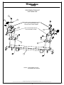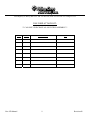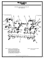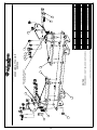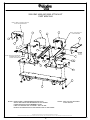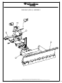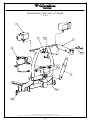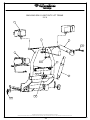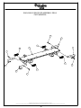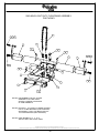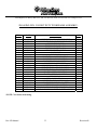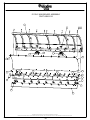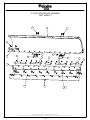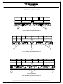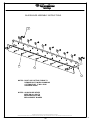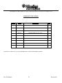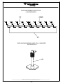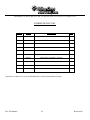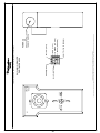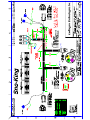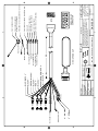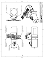
1
Gen II Light Duty Parts & Service Manual 2005 Ford F250/350, F450/550, 2005/08 GMC 4500 & 5500 Models Unit Serial Number: ________________ Record the MODEL and SERIAL NUMBER of equipment for parts ordering information. PURCHASED FROM: DATE: MODEL: SERIAL NUMBER: 22956 Highway 61 Morley, MO 63767 PH: 573-262-3545; FAX: 573-262-3369 www.vikingcives.com TABLE OF CONTENTS DESCRIPTION: PAGE NO.: WARRANTY POLICY/ORDERING PARTS WARRANTY REQUEST PROCEDURE INTRODUCTION PERIODIC MAINTENANCE INSPECTION DAILY INSPECTION AND LUBRICATION REGISTRATION OF EQUIPMENT AND WARRANTY INFORMATION 2005 FORD INSTALLATION INSTRUCTIONS DRAWING OF 2005 FORD ATTACH KIT PARTS BREAK DOWN OF 2005 FORD ATTACH KIT 2005 thru 2008 GMC 4500 & 5500 INSTALLATION INSTRUCTIONS DRAWING OF 2005 GMC 4500 & 5500 ATTACH KIT PARTS BREAK DOWN OF 2005 GMC 4500 & 5500 ATTACH KIT 2008 FORD SUPER DUTY INSTALLATION INSTRUCTIONS 2008 FORD ATTACH KIT DRAWING 2008 FORD ATTACH KIT PARTS BREAKDOWN 2008 GMC ATTACH KIT DRAWING 2008 GMC ATTACH KIT PARTS BREAKDOWN DRAWING OF SNO-KING (GEN. II) ASSEMBLY PARTS BREAK DOWN OF SNO-KING (GEN. II) ASSEMBLY DRAWING OF (GEN. II) LIGHT DUTY LIFT FRAME (4X4) PARTS BREAK DOWN OF (GEN. II) LIGHT DUTY LIFT FRAME (4X4) DRAWING OF (GEN. II) LIGHT DUTY LIFT FRAME (2X4) PARTS BREAK DOWN OF (GEN. II) LIGHT DUTY LIFT FRAME (2X4) LIGHT DUTY RECIEVER DRAWING AND PARTS BREAKDOWN CUSHION VALVES W/ CENTRAL HYDRAULIC SYTEM MAINTENANCE PROCEDURE FOR TIGHTENING NUTS ON SNOW PLOW CYLINDER TORQUE ARM REMOVEL MOLDBOARD/PUSHFRAME ASSEMBLY INSTRUCTIONS DRAWING OF (GEN. 11) LIGHT DUTY PUSHFRAME ASSEMBLY PARTS BREAK DOWN OF (GEN. II) LIGHT DUTY PUSHFRAME ASSEMBLY DRAWING OF 9’ POLY MOLDBOARD DRAWING OF 9’ STEEL MOLDBOARD PARTS BREAK DOWN 8’ MOLDBOARD PARTS BREAK DOWN 9’ MOLDBOARD PARTS BREAK DOWN 10’ MOLDBOARD DRAWING OF PLATE WASHER LAYOUT PARTS BREAK DOWN OF PLATE WASHER LAYOUT DRAWING OF TRIP HINGE PARTS BREAK DOWN OF TRIP HINGE DRAWING OF RUBBER DEFLECTOR PARTS BREAK DOWN OF RUBBER DEFLECTOR ELECTRICAL WIRING WARRANTY PAGE New LD Manual 2 3 4 5 5 5 6 7 8 9 11 12 13 15 16 17 18 19 20 21 22 23 24 25 26-27 28 29 30 31 32 33 34 35 36 37 38 40 41 42 43 44 45 46-50 51 Revision 08 22956 Highway 61 Morley, MO 63767 PH: 573-262-3545; FAX: 573-262-3369 www.vikingcives.com WARRANTY POLICY Viking-Cives Midwest, Inc. warrants products of its manufacture against defects in workmanship and material for a period of one year, from the date of shipment to the customer. In consequence of this warranty, any component part or parts of such products proving defective within the above specified time will be repaired or replaced F.O.B. factory. Providing such parts are returned, transportation prepaid, to the factory and found defective by Viking-Cives Midwest, Inc.. This warranty will not apply to any product which has been repaired or altered outside of Viking-Cives Midwest, Inc. factory in any way, so as in Viking-Cives Midwest, Inc. judgment, to affect its stability or reliability, nor which has been subject to misuse or accident. The obligations of Viking-Cives Midwest, Inc. under this warranty are limited to the replacement of defective parts. Such obligations are exclusive and in lieu of all other remedies, warranties, guarantees of liabilities, expressed or implied, with respect to each product delivered, hereunder, arising by law or otherwise (including without limitation any obligation or liability by VikingCives Midwest, Inc. arising from negligence or with respect to fitness, merchantability, loss of use, revenue, or profit, or consequential damages or injuries). This limited warranty shall not be extended, altered, or varied except by a written instrument signed by Viking-Cives Midwest, Inc.. Viking-Cives Midwest, Inc. assumes no responsibility for engines, electrical equipment or any other equipment and accessories not manufactured by Viking-Cives Midwest, Inc. beyond the warranty of the manufacturer of such equipment of accessories. All warranty work done on Viking-Cives Midwest, Inc. equipment must have prior authorization from Viking-Cives Midwest, Inc. along with a “Return Goods Authorization” number. All labor and parts issued by user for Viking-Cives Midwest, Inc. warranty without an authorization number and a signed authorization warranty form will be at the users own cost. ORDERING PARTS Delays and errors can be eliminated when ordering instructions are followed correctly. 1. Place orders direct with Viking-Cives Group/nearest dealer. 2. State Company name, address, and postal/zip code. 3. Give the exact model and serial number of the equipment/unit (stamped on the unit identification plate.) 4. Furnish part number, description and quantities required. Note: An alpha designation in the Item ID column indicates a sub-component for that parent item. When placing parts orders reference the parent item to receive a complete assembly. Individual items can be ordered separately if required by ordering the alpha designated item number. 5. Print or type order clearly. 6. Give specific shipping instructions. VIKING-CIVES (USA) – RR2, Box 36-1/2; Harrisville, New York 13648; (315) 543-2321, (315) 543-2366 Fax VIKING-CIVES MIDWEST, INC. – 22956 Highway 61; Morley, MO 63767; (573) 262-3545, (573) 262-3369 Fax VIKING-CIVES LTD. – RR4, Box 1120; Mount Forest, Ontario, Canada N0G 2L0; (519) 323-4433, (519) 323-4608 Fax New LD Manual 3 Revision 08 22956 Highway 61 Morley, MO 63767 PH: 573-262-3545; FAX: 573-262-3369 www.vikingcives.com WARRANTY REQUEST PROCEDURE All repairs considered for warranty that are performed outside of Viking-Cives Midwest, Inc.; require prior written authorization from Viking-Cives Midwest, Inc.. Failure to obtain written warranty authorization prior to repairs may result in the rejection of the warranty claim. To obtain warranty consideration one must provide all required Viking-Cives Midwest, Inc. with unit information including date of manufacture and serial numbers. In most cases this information is easily obtained from the “Shipped Unit Tag” (located in most cases inside the driver’s side door) and/or individual unit serial tag. (A) To obtain Parts Warranty Consideration: (1) Contact Viking-Cives Midwest, Inc. customer service to obtain a Return Goods Authorization (RGA) number. Any product arriving at Viking-Cives Midwest, Inc. without a RGA number will be rejected and returned to the sender at his or her own expense. (2) Goods are to be shipped prepaid to Viking-Cives Midwest, Inc. 212 North Evans Road Evansdale, Iowa 50707. All items should be clearly marked with the appropriate RGA number. (3) When a replacement item is shipped to replace a defective part for warranty consideration the following additional steps will occur: a) An invoice will be generated for the value of the replacement item(s). b) The defective part(s) must be returned (prepaid) to Viking-Cives Midwest, Inc.. c) Upon receiving the defective part(s) Viking-Cives Midwest, Inc. will issue and process a Discrepant Material Report (DMR). Once the evaluation of the DMR report is complete and the parts are deemed warranty, a credit will be issued against the outstanding invoice. If the part(s) are deemed Non-warranty the invoice will remain outstanding to be paid to Viking-Cives Midwest, Inc.. Any part(s) to be returned to the customer will be at his or her own expense. (B) To obtain Labor Parts Repair Warranty Consideration: In the event that repairs are required outside of Viking-Cives Midwest, Inc. facility that may be considered for warranty the following steps must occur. Notification of Viking-Cives Midwest, Inc. customer service must take place prior to the start of any repairs. (1) Contact Viking-Cives Midwest, Inc. customer service to obtain a Warranty Claim Form (WCF) and warranty authorization number. (2) Fill out all required WCF information and fax or mail the completed form to Viking-Cives Midwest, Inc., attention Customer Service Department. (3) Once the WCF report has been reviewed warranty authorization will be granted or denied. NOTE: VikingCives Midwest, Inc. warranty labor rates will apply unless specifically determined otherwise. Any part(s) involved in a WCF request must follow the Parts Warranty Consideration procedures. For Customer Service and/or Parts requests please contact: Service Department – DeWayne Stroder ([email protected]) Ph. (573) 262-3545; Fax (573) 262-3369 New LD Manual 4 Revision 08 22956 Highway 61 Morley, MO 63767 PH: 573-262-3545; FAX: 573-262-3369 www.vikingcives.com INTRODUCTION This instruction/parts manual has operation and maintenance information for the Viking-Cives Sno-King Equipment. It has been prepared to familiarize you with the design features of the unit, and to instruct you in its proper operation and maintenance. Read this manual carefully before you operate and/or service your Sno-King Equipment. Remember that you’re working with heavy equipment that can injure you or someone else. You can help lessen the chance of injury by following the procedures in this manual, carefully. DANGER: If incorrectly used, this equipment can cause severe injury. Your chance of injury can be greatly reduced by following all caution/warning decal notifications. All decals must be kept clean and complete. Replace any decals that are unreadable. Decals may be purchased directly from Viking-Cives Group and/or the nearest authorized dealer. All Operator/Service people should review this manual carefully and become familiar with its contents. If anyone else beside you operates or services this equipment, make sure they read this manual and are instructed to follow the safety procedures related to this equipment. PERIODIC MAINTENANCE INSPECTION DAILY INSPECTION AND LUBRICATION Daily inspection along with periodic preventive maintenance will reduce the chance of any major repairs and down time during equipment use. 1. 2. 3. 4. 5. 6. 7. 8. Check the fluid level in the hydraulic oil reservoir. If the sight indicates low oil level, add the appropriate amount of the specified hydraulic fluid. Cold Weather Operation: All equipment is designed to operate with hydraulic oil minimally warm. During cold weather conditions, it is recommended that the truck be run at idle with the pump engaged and circulating the oil through the system before operating equipment. Grease all required components: - All plow harness sheave nipples. - All pump drive shaft nipples. - Front and Rear tower sheave swivel blocks. - Wing extension arm nipples. - Front and Rear tower guide tracks. - All front harness pivot points. Check all components for loose and/or missing fasteners, if required tighten and/or replace. Visually inspect all battery terminals and electrical connections, wires, switches, etc. for signs of corrosion, wear, loose and/or broken connections, etc. At the beginning of each shift review all lighting accessories to ensure proper working conditions, immediately replace any broken or non-functioning bulbs and/or lenses. Visually inspect all hydraulic connections and hoses for cracks and/or leaks. Check all cables, chains and sheaves for excessive wear or damage. Visually inspect plow and wing units. Check cutting edges and wear shoes. If cutting edge has excessive wear remove and rotate or if required replace. CAUTION: Do not allow cutting edge to wear down to mounting angle. Any wear to the mounting angle may affect the operation and safety of the equipment. Replacement is costly. At the beginning of each shift visually inspect all caution and warning decals. All decals should be complete and legible. If decals are not legible, clean them. If cleaning the decals does not make them legible, install new decals. New LD Manual 5 Revision 08 22956 Highway 61 Morley, MO 63767 PH: 573-262-3545; FAX: 573-262-3369 www.vikingcives.com REGISTRATION OF EQUIPMENT AND WARRANTY INFORMATION Report any damage to equipment at once to Viking-Cives Midwest, Inc.. You should also register your equipment with Viking-Cives Midwest, Inc., by filing out a warranty certificate and registration card and returning them to Viking-Cives Midwest, Inc.. The warranty period becomes effective upon date of delivery of equipment unless other arrangements have been made with a Viking-Cives Midwest, Inc. Distributor or Viking-Cives Midwest, Inc.. The information required to register the equipment may be found on the serial number tag secured to the equipment. Model NO. CTE 934 / SERIAL NO._______________ 22956 Highway 61 Morley, MO 63767 Phone (573) 262-3545 / Fax (573) 262-3369 A WORD ABOUT SAFETY: The equipment described in this manual is normally being operated in adverse winter conditions with bad weather, snow and ice. Due to these adverse operating conditions it is important that you the operator use good safety practices at all time to protect yourself, coworkers and others when using the equipment. It is not practical or possible to warn you about all the hazards associated with the operation and maintenance of this equipment. You should always use your own good judgment supplemented with the information found on the safety decals, instructions in this manual, your employer’s safety programs, safety codes, local, state/provincial, and federal laws, rules and regulations. When operating/performing maintenance on this equipment, trouble shooting equipment operations and loading or unloading the sanders/spreaders with material observe & obey all safety decals on the equipment and warnings listed in the manual. Failure to do this could result in serious injury or death to you or others. Remember at all times that as the operator you are responsible for the safe operation of this equipment and responsible for the safety of others. Good safety practices not only protect you but also protect the people around you. New LD Manual 6 Revision 08 22956 Highway 61 Morley, MO 63767 PH: 573-262-3545; FAX: 573-262-3369 www.vikingcives.com 2005 FORD SUPER DUTY INSTALLATION INSTRUCTIONS – F250/350 & F450/550 1. Remove front bumper saving the fasteners for re-installation. 2. Remove tow hook fasteners. 3. Drop out blocker beam. 4. Install left and right attaching brackets utilizing the original fasteners and tow hooks. Also at this time install one 5/8” x 2” in hole 6” behind 3 tow hook bolts. 5. Install four ½” x 1 ½” bolts on side plate. 6. Position receiver plate “F” onto receiver pads and install with 5/8” x 2” bolts and locking nuts. Insert three bolts upward and one bolt down per side as shown in illustrations. 7. Verify proper frame contact and alignment of all components at this time. Adequately tighten the following fasteners is this sequence: (6) Original metric tow hook bolts (2) 5/8” x 2” bolts behind tow hook bolts (8) ½” x 1 ½” bolts on side plate (8) 5/8” x 2” bolts connecting receiver to attaching kit 8. Install lift frame release pins, springs, and cotter pins into receiver plate “F”. 9. Re-install and properly adjust bumper utilizing the original fasteners. New LD Manual 7 Revision 08 22956 HWY 61 PO BOX 295 MORLEY, MO 63767 Phone:(573)262-3545 Fax:(573)262-3369 2005 FORD ATTACH KIT PART #3SK1522 6 5 8 TWO BACK HOLES ON SIDE PLATES HAVE TO BE TRANSFERED AND DRILLED INTO TRUCK FRAME 4 USE SIX EXSISTING METRIC TOE HOOK BOLTS HERE 7 2 1 3 NOTES: ITEM NUMBER 3 IS NOT INCLUDED IN KIT 3SK1522. EQUIPMENT MAY NOT BE EXACTLY AS SHOWN. SOME COMPONENTS MAY BE OPTIONAL TO MAINTAIN OUR ON-GOING PRODUCT AND DEVELOPMENT IMPROVEMENT PROGRAM, VIKING-CIVES RESERVES THE RIGHT TO CHANGE EQUIPMENT & SPECIFICATION WITHOUT NOTICE. 8 This Owner's Manual File is Contained Within 2005 FORD ATTACH KIT.idw 22956 Highway 61 Morley, MO 63767 PH: 573-262-3545; FAX: 573-262-3369 www.vikingcives.com 2005 FORD ATTACH KIT: ** CAN ONLY PURCHASE AS AN ENTIRE ASSEMBLY** ITEM # PART # DESCRIPTION QTY 1 3SK1522 DRIVERS SIDE 1 2 3SK1522 PASSENGER SIDE 1 3 3SK2211 LD RECEIVER WELDMENT 1 4 3SK3700 BOLT HEX 5/8” X 2” UNC ZINC 10 5 3SK3600 BOLT HEX ½” X 1 ½” UNC ZINC 8 6 3SK3781 NUT HEX TOP LOCK 5/8” UNC ZINC 10 7 3SK3670 NUT HEX TOP LOCK ½” UNC ZINC 8 8 3SK3768 FLATWASHER 5/8” 2 New LD Manual 9 Revision 08 22956 Highway 61 Morley, MO 63767 PH: 573-262-3545; FAX: 573-262-3369 www.vikingcives.com NOTES ______________________________________________________ ______________________________________________________ ______________________________________________________ ______________________________________________________ ______________________________________________________ ______________________________________________________ ______________________________________________________ ______________________________________________________ ______________________________________________________ ______________________________________________________ ______________________________________________________ ______________________________________________________ ______________________________________________________ ______________________________________________________ ______________________________________________________ ______________________________________________________ ______________________________________________________ ______________________________________________________ ______________________________________________________ ______________________________________________________ ______________________________________________________ ______________________________________________________ New LD Manual 10 Revision 08 22956 Highway 61 Morley, MO 63767 PH: 573-262-3545; FAX: 573-262-3369 www.vikingcives.com 2005 to 2008 GMC INSTALLATION INSTRUCTIONS – 4500 AND 5500 1. Remove front bumper saving the fasteners for reinstallation. 2. Remove tow hooks and fasteners. 3. Install items 4 and 5 to the bottom of frame rails using the 8 metric bolts provided. Don’t tighten all the way right now. 4. Install items 6 and 7 over the top of frame rails making sure item 8 is between frame and two outside holes. Reinstall 4 OEM tow hook fasteners and tow hooks thru item 6, 7, and 8. 5. Install left and right attaching brackets to items 4, 5, 6, and 7 with fasteners provided. Don’t tighten nuts and bolts at this time. 6. Position receiver plate item 3 to the receiver pads of the left and right attaching brackets. 7. Verify proper frame contact and alignment of all components at this time. Adequately tighten the following fasteners in this sequence: (4) Original tow hooks and tow hook bolts. (8) ½” x 1 ½” in upper sections of left and right attaching brackets. (12) 5/8” x 2” bolts connecting receiver to attaching brackets. 8. Install items 9 and 11 to existing holes rearward on frame with (4) OEM fasteners already in frame. 9. Install stiffener bar (item 12) to items 9 and 11 using (2) 5/8” x 1 ¾” bolt and (2) 5/8” top lock nuts. Next install item 10 to stiffener bars (item 12) using (2) 5/8” x 1 ¾” bolts and (2) 5/8” top lock nuts. Position item 10 off the back of attaching brackets (item 1 and 2) and weld complete. 10. Install lift frame release pins, springs, and cotter pins into item 3. 11. Re-install and properly adjust bumper utilizing the original fasteners. New LD Manual 11 Revision 08 22956 HWY 61 PO BOX 295 MORLEY, MO 63767 (573)262-3545 PH (573)262-3369 FX 2005 GMC 4500 & 5500 ATTACH KIT PART #3SK1543 NOTES: ITEMS 6 & 8 MOUNT OVER THE TOP OF TRUCKS FRAME RAILS 3 2 11 NOTES: USE (4) OEM TOW HOOK FASTENERS 7 9 6 18 8 4 12 16 14 5 NOTES: REPLACE (8) OEM METRIC FASTENERS WITH ITEM #18 WHICH ARE PROVIDED 14 16 15 17 10 13 1 16 NOTES: ITEM #1 IS NOT INCLUDED IN KIT 3SK1543 NOTES: ITEMS 9 & 11 ARE REAR BRACE ARM CLIPS WHICH ARE INSTALLED REARWARD ON THE FRAME USING EXSISTING CROSS MEMBER HOLES ITEM 10 IS WELDED OFF TO ITEMS 1 & 2 AFTER REAR CLIPS ARE INSTALED AND EVERYTHING IS TIGHTENED EQUIPMENT MAY NOT BE EXACTLY AS SHOWN. SOME COMPONENTS MAY BE OPTIONAL TO MAINTAIN OUR ON-GOING PRODUCT AND DEVELOPMENT IMPROVEMENT PROGRAM, VIKING-CIVES RESERVES THE RIGHT TO CHANGE EQUIPMENT & SPECIFICATION WITHOUT NOTICE. 12 This Owner's Manual File is Contained Within GMC ATTACH KIT PRESENTATI 22956 Highway 61 Morley, MO 63767 PH: 573-262-3545; FAX: 573-262-3369 www.vikingcives.com 2005 GMC 4500 & 5500 ATTACH KIT: ** CAN ONLY PURCHASE AS AN ENTIRE ASSEMBLY** ITEM # PART # DESCRIPTION QTY 1 3SK1543R ATTACH MOUNT DRIVERS SIDE 1 2 3SK1543L ATTACH MOUNT PASSENGER SIDE 1 3 3SK2211 LD RECEIVER WELDMENT 1 4 VIK-P00270-2 ANGLE 3.000 X 3.000 X 0.375 – 9.313 1 5 VIK-P00271-2 ANGLE 3.000 X 3.000 X 0.375 – 9.313 1 6 VIK-P00257-4 PLATE 5.000 X 14.544 X 0.375 1 7 VIK-P00257-5 PLATE 6.000 X 15.500 X 0.375 1 8 VIK-P00268-2 PLATE 1.313 X 4.813 X 0.375 2 9 VIK-P00272-2 PLATE 7.375 X 9.866 X 0.375 1 10 VIK-P00274-2 PLATE 2.000 X 6.000 X 0.375 2 11 VIK-P00273-2 PLATE 7.375 X 9.866 X 0.375 1 12 VIK-P00269 STIFFINER BAR 2 13 3SK3700 BOLT HEX 5/8” X 2” UNC ZINC 12 14 3SK3699 BOLT HEX 5/8” X 1 ¾” UNC ZINC 4 15 3SK3600 BOLT HEX ½” X 1 ½” UNC ZINC 8 16 3SK3781 NUT HEX TOP LOCK 5/8” UNC ZINC 16 17 3SK3670 NUT HEX TOP LOCK ½” UNC ZINC 8 18 3SK3836 BOLT HEX M12 X 1.75 PITCH X 40 MM LG ZIN 8 New LD Manual 13 Revision 08 22956 Highway 61 Morley, MO 63767 PH: 573-262-3545; FAX: 573-262-3369 www.vikingcives.com NOTES _________________________________________________ _________________________________________________ _________________________________________________ _________________________________________________ _________________________________________________ _________________________________________________ _________________________________________________ _________________________________________________ _________________________________________________ _________________________________________________ _________________________________________________ _________________________________________________ _________________________________________________ _________________________________________________ _________________________________________________ _________________________________________________ _________________________________________________ _________________________________________________ _________________________________________________ _________________________________________________ New LD Manual 14 Revision 08 22956 Highway 61 Morley, MO 63767; PH: 573-262-3545; FAX: 573-262-3369; www.vikingcives.com 2008 FORD SUPER DUTY INSTALLATION INSTRUCTIONS – F250/350 & F450/550 1. Remove front bumper saving the fasteners for reinstallation. 2. Install left and right attaching brackets, (items 2 &3) using one ¾” x 2” bolt (item 6) and ¾” flat washer (item 7) in the formed vertical angle and one in the back hole in the side plate. Also at this time install one ½” x 2” bolt (item 9) and ½” flat washer (item 11) in the forward hole of the side plate. Place one 5/8” x 1 ½” bolt (item 10) thru the formed angle so that it goes thru the radiator hanger bracket. 3. After tightening bolts in step two, transfer holes in the bottom of the frame. After transferring the two holes, place two 5/8” x 1 ½” bolts (item 10) and 5/8” flat washer (item 13) on the inside of the truck frame. 4. Verify proper frame contact and alignment of all components at this time. 5. After verifying frame contact and alignment, loosen all bolts in step two but do not remove them all the way. 6. Install receiver weldment (item 1) to items two and three using twelve 5/8” x 2” bolts (item 4) and nuts (item 5). 7. Adequately tighten the following fasteners in this sequence: (4) Original tow hooks and tow hook bolts. (2) ½” x 2” bolts in side plate (2) 5/8” x 1 ½” bolts in formed angle (4) 5/8” x 1 ½” bolts in transformed holes in truck frame (12) 5/8” x 2” bolts connecting receiver to attaching brackets. 8. Install lift frame release pins, springs, and cotter pins into receiver weldment (item 1) 9. Re-install and properly adjust bumper utilizing the original fasteners. 16 This Owner's Manual File is Contained Within 3SK1524 ASS'Y.idw 4 5 10 1 3 8 11 ITEM NUMBER 1 IS NOT INCLUDED IN KIT 3SK1524 NOTES 2 12 7 10 ITEM DRAWING NO. ALT. ITEM NO. 1 3SK2211 2 3SK1524-L 3 3SK1524-R 4 3SK3700 81073D 5 3SK3781 6 32K3795 81064E 7 81062X 3SK3820 8 3SK3811 9 3SK3610 81083 10 3SK3698 81072 11 3SK3661 12 3SK3670 13 233819 81070A EQUIPMENT MAY NOT BE EXACTLY AS SHOWN. SOME COMPONENTS MAY BE OPTIONAL TO MAINTAIN OUR ON-GOING PRODUCT AND DEVELOPMENT IMPROVEMENT PROGRAM, VIKING-CIVES RESERVES THE RIGHT TO CHANGE EQUIPMENT & SPECIFICATION WITHOUT NOTICE. 13 THESE FOUR HOLES MUST BE TRANSFERED INTO BOTTOM OF TRUCK FRAME. 2008 FORD ATTACH KIT 3SK1524 22956 HWY 61 MORLEY, MO 63767 (573)262-3545 PH (573)262-3369 FX 6 DESCRIPTION LD RECIEVER WELDMENT 2008 ATTACHING WELDMENT PASS SIDE 2008 ATTACHING WELDMENT DRVS SIDE BOLT HEX 5/8 X 2 UNC ZINC NUT HEX TOPLOCK 5/8" UNC ZINC BOLT HEX 3/4 X 2 UNC ZINC FLATWASHER SAE 3/4" ZINC NUT HEX TOPLOCK 3/4" UNC ZINC BOLT HEX 1/2 X 2 UNC ZINC BOLT HEX 5/8 X 1 1/2 UNC ZINC FLATWASHER SAE 1/2 ZINC NUT HEX TOPLOCK 1/2" UNC ZINC FLATWASHER SAE 5/8 ZINC 9 QTY 1 1 1 12 18 4 4 4 2 6 2 2 4 22956 Highway 61 Morley, MO 63767 PH: 573-262-3545; FAX: 573-262-3369 www.vikingcives.com 3SK1524: 2008 FORD ATTACH KIT ** CAN ONLY PURCHASE AS AN ENTIRE ASSEMBLY** ITEM # PART # 1 DESCRIPTION QTY 3SK2211 LD RECEIVER WELDMENT 1 2 3SK1524-L 2008 ATTACHING WELDMENT PASS SIDE 1 3 3SK1524-R 2008 ATTACHING WELDMENT DRIVER SIDE 1 4 3SK3700 BOLT HEX 5/8 X 2 UNC ZINC 12 5 3SK3781 NUT HEX TOPLOCK 5/8” UNC ZINC 18 6 3SK3795 81064E BOLT HEX ¾ X 2 UNC ZINC 4 7 3SK3820 81062X FLATWASHER SAE ¾” ZINC 4 8 3SK3811 NUT HEX TOPLOCK ¾” UNC ZINC 4 9 3SK3610 81083 BOLT HEX ½ X 2 UNC ZINC 2 10 3SK3698 81072 BOLT HEX 5/8 X 1 ½ UNC ZINC 6 11 3SK3661 FLATWASHER SAE ½ ZINC 2 12 3SK3670 NUT HEX TOPLOCK ½” UNC ZINC 2 13 233819 FLATWASHER SAE 5/8 ZINC 4 New LD Manual ALT PART # 81073D 81070A 17 Revision 08 212 NORTH EVANS ROAD, EVANSDALE, IOWA 50707 (319)236-7977 PH (319)236-7980 FX 2008 GMC 4500 AND 5500 ATTACH KIT PART #3SK1544 NOTES: ITEMS 6 & 8 MOUNT OVER THE TOP OF TRUCK FRAME RAILS 11 7 3 2 NOTES: USE (4) OEM TOW HOOK FASTENERS 9 6 8 18 4 12 16 NOTES: REPLACE (8) OEM METRIC FASTENERS WITH ITEM 18 WHICH ARE APPROVED 14 5 14 16 15 17 10 13 16 1 NOTES: ITEMS 9 AND 11 ARE REAR BRACE ARM CLIPS WHICH ARE INSTALLED REARWARD ON THE FRAME USING EXSISTING CROSS MEMBER HOLES ITEM 10 IS WELDED OFF TO ITEMS 1 AND 2 AFTER REAR CLIPS ARE INSTALLED AND EVERYTHING IS TIGHTENED NOTES: ITEM 1 IS NOT INCLUDED IN KIT 3SK1544 EQUIPMENT MAY NOT BE EXACTLY AS SHOWN. SOME COMPONENTS MAY BE OPTIONAL TO MAINTAIN OUR ON-GOING PRODUCT AND DEVELOPMENT IMPROVEMENT PROGRAM, VIKING-CIVES RESERVES THE RIGHT TO CHANGE EQUIPMENT & SPECIFICATION WITHOUT NOTICE. 16 This Owner's Manual File is Contained Within 2008 GMC ATTACH KIT.idw 22956 Highway 61 Morley, MO 63767 PH: 573-262-3545; FAX: 573-262-3369 www.vikingcives.com 3SK1544: 2008 GMC 4500 & 5500 ATTACH KIT ** CAN ONLY PURCHASE AS AN ENTIRE ASSEMBLY** ITEM # PART # 1 DESCRIPTION QTY 3SK2211 LD RECEIVER WELDMENT 1 2 20303034 ATTACH MOUNT DRV SIDE 2008 GMC 1 3 20303035 ATTACH MOUNT PASS SIDE 2008 GMC 1 4 20306037 UNDER FRAME MOUNTING ANGLE 1 5 20306038 UNDER FRAME MOUNTING ANGLE 1 6 20322014 FRAME HANGER PLATE PASS SIDE 1 7 20322013 FRAME HANGER PLATE DRIVER SIDE 1 8 20305082 SPACER PLATE FRAME HANGER 2 9 20322011 REAR BRACE ARM PLATE DRIVER SIDE 1 10 20305083 BRACE ARM ATTACHING LUG 2 11 20322012 REAR BRACE ARM PLATE PASS SIDE 1 12 20303036 BRACE ARM WELDMENT 2 13 HW40A-1016 BOLT HEX 5/8 X 2 UNC ZINC 12 14 3SK3699 BOLT HEX 5/8” X 1 3/4” UNC ZINC 4 15 3SK3600 BOLT HEX ½” X 1 ½” UNC ZINC 8 16 3SK3781 NUT HEX TOPLOCK 5/8” UNC ZINC 16 17 3SK3670 NUT HEX TOPLOCK ½” UNC ZINC 8 18 3SK3836 BOLT HEX M12 X 1.75 PITCH X 40 MM LG ZINC 8 New LD Manual ALT PART # 81073D 19 Revision 08 22956 HWY 61 PO BOX 295 MORLEY, MO 63767 (573)262-3545 PH (573)262-3369 FX SNO-KING (GEN. II) ASSEMBLY 5 3 4 1 2 EQUIPMENT MAY NOT BE EXACTLY AS SHOWN. SOME COMPONENTS MAY BE OPTIONAL TO MAINTAIN OUR ON-GOING PRODUCT AND DEVELOPMENT IMPROVEMENT PROGRAM, VIKING-CIVES RESERVES THE RIGHT TO CHANGE EQUIPMENT & SPECIFICATION WITHOUT NOTICE. This Owner's Manual File is Contained Within NEW SNO-KING ASSEMBLY.idw 22956 Highway 61 Morley, MO 63767 PH: 573-262-3545; FAX: 573-262-3369 www.vikingcives.com SNO-KING GEN. II ASSEMBLY ITEM # PART # DESCRIPTION QTY 1 3SK2106 8’ POLY MOLDBOARD ASSEMBLY 1 1 3SK2116 9’ POLY MOLDBOARD ASSEMBLY 1 1 3SK2126 10’ POLY MOLDBOARD ASSEMBLY 1 1 3SK2107 8’ STEEL MOLDBOARD ASSEMBLY 1 1 3SK2117 9’ STEEL MOLDBOARD ASSEMBLY 1 1 3SK2127 10’ STEEL MOLDBOARD ASSEMBLY 1 2 3SK3 LD PUSH FRAME ASSEMBLY 1 3 3SK2200-2GM 2005 SNO-KING LD LIFT FRAME (2X4) 1 4 3SK2209 SNO-KING LD RECEIVER ASSEMBLY 1 5 3SK4056M ELECTRIC HYDRAULIC POWER UNIT 1 New LD Manual 21 Revision 08 22956 HWY 61 PO BOX 295 MORLEY, MO 63767 (573)262-3545 PH (573)262-3369 FX SNO-KING GEN II LIGHT DUTY LIFT FRAME 4X4 4 1 12 7 3 2 8 13 9 10 11 5 7 13 12 6 EQUIPMENT MAY NOT BE EXACTLY AS SHOWN. SOME COMPONENTS MAY BE OPTIONAL TO MAINTAIN OUR ON-GOING PRODUCT AND DEVELOPMENT IMPROVEMENT PROGRAM, VIKING-CIVES RESERVES THE RIGHT TO CHANGE EQUIPMENT & SPECIFICATION WITHOUT NOTICE. 22 This Owner's Manual File is Contained Within NEW FORD LIFT FRAME.idw 22956 Highway 61 Morley, MO 63767 PH: 573-262-3545; FAX: 573-262-3369 www.vikingcives.com SNO-KING GEN. II LIGHT DUTY LIFT FRAME (4X4): ITEM # PART # DESCRIPTION QTY 1 3SK2200-2 2005 SNO-KING LD LIFT FRAME 1 2 3SK2220-2 LD LIFT ARM WELDMENT 1 3 3SK4000 LIFT CYLINDER 1 ½” X 8” 1 4 3SK6010TLN PLOW LIGHTS 1 5 3SK4056M ELECTRIC HYDRAULIC POWER UNIT 1 6 3SK2290 INSTA SHOE 1 7 3SK3411 HANDLE PIN 1” X 3 ¾” 2 8 3SK3400 PIN 1” X 3 ½” 1 9 3SK3410 PIN 1” X 4” 2 10 3SK3405 PIN 5/8” X 3” UH 1 11 2S20A-2 QUICK COUPLING ¼” 2 12 3SK3586 CAP SCREW SOCKET HEAD 3/8” X 1” NC BLACK 2 13 3SK3582 LOCK WASHER SPLIT 3/8” ZINC 2 14 280518 COTTER PIN 3/16” X 2 ½” ZINC 2 15 3SK3460 COTTER HAIR PIN 3/16” X 3 ¾” 3 16 20120710 LYNCH PIN 3/16” X 1 9/16” ZINC 1 New LD Manual 23 Revision 08 22956 HWY 61 PO BOX 295 MORLEY, MO 63767 (573)262-3545 PH (573)262-3369 FX SNO-KING GEN. II LIGHT DUTY LIFT FRAME 2X4 4 1 3 8 13 5 12 13 8 11 12 5 14 6 8 15 EQUIPMENT MAY NOT BE EXACTLY AS SHOWN. SOME COMPONENTS MAY BE OPTIONAL TO MAINTAIN OUR ON-GOING PRODUCT AND DEVELOPMENT IMPROVEMENT PROGRAM, VIKING-CIVES RESERVES THE RIGHT TO CHANGE EQUIPMENT & SPECIFICATION WITHOUT NOTICE. 24 This Owner's Manual File is Contained Within NEW GMC LIFT FRAME.idw 22956 Highway 61 Morley, MO 63767 PH: 573-262-3545; FAX: 573-262-3369 www.vikingcives.com SNO-KING GEN. II LIGHT DUTY LIFT FRAME (2X4): ITEM # PART # DESCRIPTION QTY 1 3SK2200-2GM 2005 SNO-KING LD LIFT FRAME 1 2 3SK2220-2 LD LIFT ARM WELDMENT 1 3 3SK4000 LIFT CYLINDER 1 ½” X 8” 1 4 3SK6010TLN PLOW LIGHTS 1 5 3SK4056M ELECTRIC HYDRAULIC POWER UNIT 1 6 3SK2290 INSTA SHOE 1 7 3SK3411 HANDLE PIN 1” X 3 ¾” 2 8 3SK3400 PIN 1” X 3 ½” 1 9 3SK3410 PIN 1” X 4” 2 10 3SK3405 PIN 5/8” X 3” UH 1 11 2S20A-2 QUICK COUPLING ¼” 2 12 3SK3586 CAP SCREW SOCKET HEAD 3/8” X 1” NC BLACK 2 13 3SK3582 LOCK WASHER SPLIT 3/8” ZINC 2 14 280518 COTTER PIN 3/16” X 2 ½” ZINC 2 15 3SK3460 COTTER HAIR PIN 3/16” X 3 ¾” 3 16 20120710 LYNCH PIN 3/16” X 1 9/16” ZINC 1 New LD Manual 25 Revision 08 22956 HWY 61 P.O. BOX 295 Morley, MO. 63767 Phone: (573)262-3545 Fax: (573)262-3369 SNO-KING LD RECIEVER ASSEMBLY GEN II PART #3SK2209 4 2 3 2 1 3 4 3 4 2 3 2 4 EQUIPMENT MAY NOT BE EXACTLY AS SHOWN. SOME COMPONENTS MAY BE OPTIONAL TO MAINTAIN OUR ON-GOING PRODUCT AND DEVELOPMENT IMPROVEMENT PROGRAM, VIKING-CIVES RESERVES THE RIGHT TO CHANGE EQUIPMENT & SPECIFICATION WITHOUT NOTICE. 26 This Owner's Manual File is Contained Within 3SK2209-2.idw 22956 Highway 61 Morley, MO 63767 PH: 573-262-3545; FAX: 573-262-3369 www.vikingcives.com 3SK2209: LIGHT DUTY RECEIVER PARTS ITEM # PART # DESCRIPTION QTY 1 3SK2211 LD RECEIVER WELDMENT 1 2 3SK3482 GEN II SPRING PIN 4 3 280518 COTTER PIN 3/16” X 2 ½” ZINC 4 4 3SK3482 GEN II SPRING PIN SPRING 4 New LD Manual 27 Revision 08 22956 Highway 61 Morley, MO 63767 PH: 573-262-3545; FAX: 573-262-3369 www.vikingcives.com SNO-KING CUSHION VALVES WITH CENTRAL HYDRAULIC SYSTEMS: A cushion valve is always required in the reverse circuit of a Sno-King snowplow! When you purchase a package which includes an electric / hydraulic power unit, a relief valve is an integral part of the power unit reverse valve. When you purchase a Sno-King light duty package less hydraulics (SK0110, SK0110P, SK0210, SK0210P, SK0310, & SK0310P) no cushion valve is included in the package – we consider them to be a part of the hydraulic package. A cushion valve for reverse cylinder protection must be included in your hydraulic package or certain cylinder failure will result. We recommend a cushion valve with a relief setting between 2250 – 2500 psi (maximum working pressure of the reverse cylinder is 2500 psi). The majority of our Dealers have opted to supply their own cushion valves. Sno-King will make an optional cushion valve available to those that wish to purchase them from us. New LD Manual 28 Revision 08 22956 Highway 61 Morley, MO 63767 PH: 573-262-3545; FAX: 573-262-3369 www.vikingcives.com MAINTENANCE PROCEDURE: TIGHTENING PACKING NUTS ON SNOW PLOW CYLINDERS Adjusting packing nuts are used on snowplow cylinders to hold the cylinder together as well as providing pressure against the chevron style rod packing. As the nut is tightened, the v – shaped packing flare out and seal tightly against the rod surface. Often times, it is necessary to adjust the packing nut in the field if oil starts to leak from the cylinder. This occurs because the seals tend to wear in after 100 cycles and need to have more pressure applied to them. The proper adjustment procedure for the packing nut is listed below: 1. Loosen the packing nut. 2. Tighten the packing nut by hand until it is snug against the packing 3. Use a nut wrench to tighten the nut ¾ turn. This simple procedure should produce a torque valve on the nut of 50 foot-pounds and should provide a dry rod when cycled. New LD Manual 29 Revision 08 22956 Highway 61 Morley, MO 63767 PH: 573-262-3545; FAX: 573-262-3369 www.vikingcives.com TORQUE ARM REMOVAL: Proper torque arm removal is accomplished by pulling the arms from the torque tube assembly via the threaded portion of the inner shaft. Never attempt to pound out the arms, as the arms will be damaged. To install the arms, adequately lubricate the inside of the torque tube, the outside of the torque arms, and press the arms into the torque tube while protecting the threads. Please contact DeWayne at 573-262-3545 if you have any questions. New LD Manual 30 Revision 08 22956 Highway 61 Morley, MO 63767 PH: 573-262-3545; FAX: 573-262-3369 www.vikingcives.com SNO-KING MOLDBOARD / PUSHFRAME ASSEMBLY INSTRUCTIONS: 1. Position the moldboard assembly face down on a flat surface. 2. Remove the factory installed 1” and ¾” fasteners from the left and right torque arm assemblies. 3. Utilizing adequate lifting equipment and proper safety procedures, position the torque tube and A-frame assembly into the rear moldboard cavity and attach with the 1” x 2 ½” fine thread bolts and flat washers, (a coating of premium grade anti-seize thread compound is recommended) but do not completely tighten at this time. 4. Rotate the torque tube and A-frame assembly towards the moldboard and attach, but do not completely tighten at this time, the torque arms to the center moldboard rib adjusting holes with the ¾” x 2 ½” bolts and nuts while positioning the flat washer on the moldboard side of the ribs. 5. Apply thread sealant onto the 90-degree pipefittings and install into the moldboard reversing cylinders. 6. Attach the correct reversing cylinder hose assemblies as indicated in the parts and service manual for your hydraulic application. A cushion valve is required on all central hydraulic systems. (Please note memo on page 18) 7. Connect each end of the lift chain assembly to the A-frame lifting lug with the ½” clevis mid link provided. 8. Once the completed plow assembly has been properly installed on the truck it will be necessary to adjust the moldboard to an angle of attack of 22 – 25 degrees and adequately tighten both the torque tube and torque arm fasteners at that time. New LD Manual 31 Revision 08 212 NORTH EVANS ROAD, EVANSDALE, IOWA 50707 (319)236-7977 PH (319)236-7980 FX SNO-KING LIGHT DUTY PUSHFRAME ASSEMBLY PART #3SK3 7 15 18 20 8 2 22 10 12 21 10 22 1 14 19 20 18 3 9 22 6 11 9 4 19 16 5 19 13 19 17 NOTES: ITEM NUMBER 23 IS NOT SHOWN ORDERED IF YOU ARE USING CENTRAL HYDRAULICS INSTEAD OF ITEM NUMBER 22 NOTES: OPTIONAL 1 1/2 X 8 REV CYLINDER AVALIBLE FOR 10' LD MOLDBOARDS (PART #3SK4000) STANDARD 2 X 8 REV CYLINDERS FOR ALL 10' LD MOLDBOARDS (PART #3SK4020) NOTES: ITEMS NUMBER 5, 13, 17, & 19 ARE NOT SOLD WITH PART #3SK3 EQUIPMENT MAY NOT BE EXACTLY AS SHOWN. SOME COMPONENTS MAY BE OPTIONAL TO MAINTAIN OUR ON-GOING PRODUCT AND DEVELOPMENT IMPROVEMENT PROGRAM, VIKING-CIVES RESERVES THE RIGHT TO CHANGE EQUIPMENT & SPECIFICATION WITHOUT NOTICE. 32 This Owner's Manual File is Contained Within 3SK3.idw 14 15 22956 Highway 61 Morley, MO 63767 PH: 573-262-3545; FAX: 573-262-3369 www.vikingcives.com SNO-KING GEN. II LIGHT DUTY PUSHFRAME ASSEMBLY: ITEM # PART # DESCRIPTION QTY 1 2 3 4 5 6 7 8 9 10 11 12 13 14 15 16 17 18 19 20 21 22 23* 24* 3SK3 3SK2132 3SK2182 3SK2155-R 3SK2155-L 3SK4000 3SK3488 LIGHT DUTY A-FRAME WELDMENT LIGHT DUTY TORQUE TUBE WELDMENT SWIVEL WELDMENT TRIPPING TORQUE ARM TRIPPING TORQUE ARM LIFT CYLINDER 1 ½” X 8” ½” MID LINK 3/8” CHAIN BOLT HEX 1 ½” X 7” UNC ZINC BOLT HEX 1” X 3” UNC ZINC BOLT HEX 1” X 2 ½” SAE ZINC BOLT ¾” X 2 ½” UNC ZINC NUT HEX TOP LOCK 1 ½” UNC ZINC NUT HEX TOP LOCK 1” UNC ZINC NUT HEX TOP LOCK ¾” UNC ZINC FLAT WASHER SAE 1” ZINC FLAT WASHER SAE ¾” ZINC PIN 1” X 5 ½” PIN 1.000 DIA X 3.406 BUSHING 1.500N 1.000M 0.906S ¼” 90 DEGREE SWIVEL ADAPTER COTTER PIN ¼” X 2 ½” ZINC ¼” X 33” HOSE FOR ELECTRONIC HYDRAULICS* ¼” X 40” HOSE FOR CENTRAL HYDRAULICS* 1 1 1 1 1 2 1 1 1 2 2 1 1 2 6 2 2 2 2 2 2 4 2 2 281027 3SK3833 3SK3830 3SK3800 237286 237278 3SK3811 281013A 3SK3820 3SK3421 20900004 20129002 3SK4120 280518 3SK4080* 3SK4090* *NOTE: Not shown in drawing. New LD Manual 33 Revision 08 22956 HWY 61 MORLEY, MO. USA 63767 Phone: (573)262-3545 (319)262-3369 9' POLY MOLDBOARD ASSEMBLY PART #3SK2116 1 15 6 16 17 6 13 13 2 17 14 7 10 7 8 7 15 7 11 4 5 9 15 12 3 EQUIPMENT MAY NOT BE EXACTLY AS SHOWN. SOME COMPONENTS MAY BE OPTIONAL TO MAINTAIN OUR ON-GOING PRODUCT AND DEVELOPMENT IMPROVEMENT PROGRAM, VIKING-CIVES RESERVES THE RIGHT TO CHANGE EQUIPMENT & SPECIFICATION WITHOUT NOTICE. 34 This Owner's Manual File is Contained Within 9 ft blade assem.idw 22956 HWY 61, MORLEY, MO. USA 63767 Phone: (573)262-3545 Fax: (573)262-3369 9' STEEL MOLDBOARD ASSEMBLY PART #3SK2117 12 1 12 9 13 4 13 6 5 6 7 5 6 6 13 3 11 2 8 13 EQUIPMENT MAY NOT BE EXACTLY AS SHOWN. SOME COMPONENTS MAY BE OPTIONAL TO MAINTAIN OUR ON-GOING PRODUCT AND DEVELOPMENT IMPROVEMENT PROGRAM, VIKING-CIVES RESERVES THE RIGHT TO CHANGE EQUIPMENT & SPECIFICATION WITHOUT NOTICE. 35 This Owner's Manual File is Contained Within 3SK2117.idw 22956 Highway 61 Morley, MO 63767 PH: 573-262-3545; FAX: 573-262-3369 www.vikingcives.com SNO-KING MODEL DT 8’ LD MOLDBOARD ASSEMBLY: ITEM # PART # DESCRIPTION QTY 1 1 2 3 4 5 6 8 9 10 11 12 13 14 15 16 17 18 3SK2100 3SK2105 3SK7055 3SK7102 3SK7051 3SK2281 3SK7164 3SK2285 3SK7020 3SK3722 2N81074 3SK3720 3SK3698 3SK3585 3SK3781 3SK3591 3SK3595 3SK3768 8’ STEEL MOLDBOARD 8’ POLY MOLDBOARD * 8’ POLY SHEET * 5/8” X 6” X 96” CUTTING EDGE 96” ADIPRENE TRIP HINGE HINGE STOP WITH FASTENERS PLATE WASHER 18” CURB SHOE 28” PLOW MARKERS BOLT HEX 5/8” X 3 ½” UNC ZINC GRADE 8 5/8” X 3” PLOW BOLT 5/8” 3” GRADE 5 CARRIAGE BOLT BOLT HEX 5/8” X 1 ½” UNC ZINC GRADE 8 BOLT HEX 3/8” X 1 ½” UNC ZINC GRADE 8 * NUT HEX TOP LOCK 5/8” UNC ZINC NUT HEX TOP LOCK 3/8” UNC ZINC * FLAT WASHER SAE 3/8” ZINC * 5/8” X 2 ½” O.D. WASHER 1 1 1 1 1 2 4 1 1 2 10 10 6 20 22 20 40 10 *USED ON 8’ POLY MOLDBOARDS ONLY New LD Manual 36 Revision 08 22956 Highway 61 Morley, MO 63767 PH: 573-262-3545; FAX: 573-262-3369 www.vikingcives.com SNO-KING MODEL DT 9’ LD MOLDBOARD ASSEMBLY: ITEM # PART # DESCRIPTION QTY 1 1 2 3 4 5 6 7 8 9 10 11 12 13 14 15 16 17 18 3SK2115 3SK2110 3SK7066 3SK7112 3SK7061 3SK2281 3SK7164 3SK7165 3SK2285 3SK7020 3SK3722 2N81074 3SK3720 3SK3698 3SK3585 3SK3781 3SK3591 3SK3595 3SK3768 9’ STEEL MOLDBOARD 9’ POLY MOLDBOARD * 9’ POLY SHEET * 5/8” X 6” X 108” CUTTING EDGE 108” ADIPRENE TRIP HINGE HINGE STOP WITH FASTENERS PLATE WASHER 18” PLATE WASHER 10” CURB SHOE 28” PLOW MARKERS BOLT HEX 5/8” X 3 ½” UNC ZINC GRADE 8 5/8” X 3” PLOW BOLT 5/8” 3” GRADE 5 CARRIAGE BOLT BOLT HEX 5/8” X 1 ½” UNC ZINC GRADE 8 BOLT HEX 3/8” X 1 ½” UNC ZINC GRADE 8 * NUT HEX TOP LOCK 5/8” UNC ZINC NUT HEX TOP LOCK 3/8” UNC ZINC * FLAT WASHER SAE 3/8” ZINC * 5/8” X 2 ½” O.D. WASHER 1 1 1 1 1 2 4 1 1 1 2 11 12 6 20 31 20 40 11 *USED ON 9’ POLY MOLDBOARDS ONLY New LD Manual 37 Revision 08 22956 Highway 61 Morley, MO 63767 PH: 573-262-3545; FAX: 573-262-3369 www.vikingcives.com SNO-KING MODEL DT 10’ LD MOLDBOARD ASSEMBLY: ITEM # PART # DESCRIPTION QTY 1 1 2 3 4 5 NOT SHOWN NOT SHOWN 8 9 10 11 12 13 14 15 16 17 18 3SK2121 3SK2125 3SK7076 3SK7121 3SK7071 3SK2281 3SK7166 3SK7167 3SK2285 3SK7030 3SK3722 2N81074 3SK3720 3SK3698 3SK3585 3SK3781 3SK3591 3SK3595 3SK3768 10’ STEEL MOLDBOARD 10’ POLY MOLDBOARD * 10’ POLY SHEET * 5/8” X 6” X 120” CUTTING EDGE 120” ADIPRENE TRIP HINGE HINGE STOP WITH FASTENERS PLATE WASHER 26” UPPER PLATE WASHER 6” UPPER CURB SHOE 36” PLOW MARKERS BOLT HEX 5/8” X 3 ½” UNC ZINC GRADE 8 5/8” X 3” PLOW BOLT 5/8” 3” GRADE 5 CARRIAGE BOLT BOLT HEX 5/8” X 1 ½” UNC ZINC GRADE 8 BOLT HEX 3/8” X 1 ½” UNC ZINC GRADE 8 * NUT HEX TOP LOCK 5/8” UNC ZINC NUT HEX TOP LOCK 3/8” UNC ZINC * FLAT WASHER SAE 3/8” ZINC * 5/8” X 2 ½” O.D. WASHER 1 1 1 1 1 2 3 2 1 1 3 12 10 6 24 29 24 48 12 *USED ON 10’ POLY MOLDBOARDS ONLY New LD Manual 38 Revision 08 22956 Highway 61 Morley, MO 63767 PH: 573-262-3545; FAX: 573-262-3369 www.vikingcives.com NOTES _________________________________________________ _________________________________________________ _________________________________________________ _________________________________________________ _________________________________________________ _________________________________________________ _________________________________________________ _________________________________________________ _________________________________________________ _________________________________________________ _________________________________________________ _________________________________________________ _________________________________________________ _________________________________________________ _________________________________________________ _________________________________________________ _________________________________________________ _________________________________________________ _________________________________________________ _________________________________________________ New LD Manual 39 Revision 08 22956 HWY 61 PO BOX 295 MORLEY, MO 63767 (573)262-3545 PH (573)262-3369 FX PLATE WASHER LAYOUT 1 8 FT MOLDBOARD PART NUMBER 3SK8WK HARDWARE KIT 1 2 1 1 9 FT MOLDBOARD PART NUMBER 3SK9WK HARDWARE KIT 4 4 3 10 FT MOLDBOARD PART NUMBER 3SK10WK HARDWARE KIT EQUIPMENT MAY NOT BE EXACTLY AS SHOWN. SOME COMPONENTS MAY BE OPTIONAL TO MAINTAIN OUR ON-GOING PRODUCT AND DEVELOPMENT IMPROVEMENT PROGRAM, VIKING-CIVES RESERVES THE RIGHT TO CHANGE EQUIPMENT & SPECIFICATION WITHOUT NOTICE. 40 This Owner's Manual File is Contained Within PLATE WASHER LAYOUT.idw 22956 Highway 61 Morley, MO 63767 PH: 573-262-3545; FAX: 573-262-3369 www.vikingcives.com PLATE WASHER LAYOUT: ITEM # PART # DESCRIPTION 1 3SK7164 PLATE WAHSER 18” 2 3SK7165 PLATE WASHER 10” 3 3SK7166 PLATE WASHER 26” 4 3SK7167 PLATE WASHER 6” New LD Manual 41 QTY Revision 08 22956 HWY 61 PO BOX 295 MORLEY, MO 63767 (573)262-3545 PH (573)262-3369 FX BLADE/HINGE ASSEMBLY INSTRUCTIONS 4 5 3 2 1 NOTES: DON'T USE CUTTING TORCH TO REMOVE BOLTS WHEN CHANGING CUTTING EDGE. IT WILL RUIN ADIPRENE HINGE. NOTES: ALWAYS USE NEVER SEIZE ON ALL BOLTS WHEN REINSTALLING REPLACEMENT BLADES EQUIPMENT MAY NOT BE EXACTLY AS SHOWN. SOME COMPONENTS MAY BE OPTIONAL TO MAINTAIN OUR ON-GOING PRODUCT AND DEVELOPMENT IMPROVEMENT PROGRAM, VIKING-CIVES RESERVES THE RIGHT TO CHANGE EQUIPMENT & SPECIFICATION WITHOUT NOTICE. 42 This Owner's Manual File is Contained Within BLADE-HINGE ASSEMBLY.idw 22956 Highway 61 Morley, MO 63767 PH: 573-262-3545; FAX: 573-262-3369 www.vikingcives.com ADIPRENE TRIP HINGE: ITEM # PART # DESCRIPTION QTY 1 3SK7051 96” ADIPRENE TRIP HINGE 1 1 3SK7061 108” ADIPRENE TRIP HINGE 1 1 3SK7071 120” ADIPRENE TRIP HINGE 1 2 3SK7102 CUTTING EDGE 5/8” X 6” X 96” 1 2 3SK7112 CUTTING EDGE 5/8” X 6” X 108” 1 2 3SK7121 CUTTING EDGE 5/8” X 6” 120” 1 3 3SK3725 5/8” X 3” GRADE 5 CARRIAGE BOLT 11 4 3SK3781 NUT HEX TOP LOCK 5/8” UNC ZINC 11 5 3SK 3768 5/8 X 2 ½” O.D. WASHER 11 *QUANTITY OF BOLTS, NUTS, AND WASHER WILL CHANGE DEPENDING ON SIZE* New LD Manual 43 Revision 08 22956 HWY 61 PO BOX 295 MORLEY, MO 63767 (573)262-3545 PH (573)262-3369 FX SNO-KING RUBBER DEFLECTOR 9' REPRESENTED 2 4 6 5 1 SNO-KING MUSHROOM SHOE, PIN, & WASHERS PART #3SK2279 3 EQUIPMENT MAY NOT BE EXACTLY AS SHOWN. SOME COMPONENTS MAY BE OPTIONAL TO MAINTAIN OUR ON-GOING PRODUCT AND DEVELOPMENT IMPROVEMENT PROGRAM, VIKING-CIVES RESERVES THE RIGHT TO CHANGE EQUIPMENT & SPECIFICATION WITHOUT NOTICE. 44 This Owner's Manual File is Contained Within RUBBER DEFLECTOR.idw 22956 Highway 61 Morley, MO 63767 PH: 573-262-3545; FAX: 573-262-3369 www.vikingcives.com RUBBER DEFLECTOR: ITEM # PART # DESCRIPTION QTY 1 3SK7130 8’ RUBBER DEFLECTOR 1 1 3SK7140 9’ RUBBER DEFLECTOR 1 1 3SK7150 10’ RUBBER DEFLECTOR 1 2 3SK7155 8’ RETAINER STRIP 1 2 3SK7156 9’ RETAINER STRIP 1 2 3SK7157 10’ RETAINER STRIP 1 3 3SK2279 SKID SHOE, WASHERS, AND PIN 2 4 3SK3585 BOLT HEX 3/8” X 1 ½” UNC ZINC 10 5 3SK3595 FLAT WASHER SAE 3/8” ZINC 20 6 3SK3591 NUT HEX TOP LOCK 3/8” UNC ZINC 10 *QUANTITY OF BOLTS, NUTS, AND WASHER WILL CHANGE DEPENDING ON SIZE* New LD Manual 45 Revision 08 46 This Owner's Manual File is Contained Within SNO-KING REMOTE.idw AUX LEFT REVERSE PLOW D O W N U P PLOW POWER FLOAT BLUE (MOTOR) GREEN (RIGHT) WHITE ( FLOAT [DOWN]) ORANGE (UP COIL) BLACK (GROUND) RED (+ 12V) YELLOW (LEFT) POWER: ON OFF PRESSURE RELEASE TOGGLE SWITCH EQUIPMENT MAY NOT BE EXACTLY AS SHOWN. SOME COMPONENTS MAY BE OPTIONAL TO MAINTAIN OUR ON-GOING PRODUCT AND DEVELOPMENT IMPROVEMENT PROGRAM, VIKING-CIVES RESERVES THE RIGHT TO CHANGE EQUIPMENT & SPECIFICATION WITHOUT NOTICE. RIGHT REVERSE POWER: ON OFF PRESSURE RELEASE SNO-KING REMOTE PART #3SK4064 22956 HWY 61 MORLEY, MO 63767 Phone:(573)262-3545 Fax:(573)262-3369 A B 2 M1 15 11 9 8 6 5 3 2 1 2 MATERIAL: DRAWN BY: KMK DATE: 9/22/2004 CHECKED BY: DATE: DWG SIZE: ANSI A SCALE: ALT. ITEM: EST. UNITS: 3/8 ID C - 0.0 TO + 0.03 HIGH AMP WIRES 78'' LONG COLORS: PIN 1 BLACK PIN 2 RED WIRE SGT 4 AWG END RING TERMINALS NOTES: GREASE FEMALE TERMINALS 10 PIN #1 GROUN/AUX GROUND PIN #2 12 VDC (+) PIN #3 BROWN (PUMP SOLENOID) PIN #5 BLUE/BLACK (?) PIN #6 RED (LEFT ANGLE) PIN #8 GREEN/BLACK (RIGHT ANGLE) PIN #9 GREEN/YELLOW (AUTO LIGHT TRANSFER) PIN #11 ORANGE/WHITE (FLOAT) PIN #15 RED/BLACK (12 VDC (+)) SNO-KING 13 9 4 1 14 5 10 15 6 2 16 7 11 8 THIRD-ANGLE PROJECTION DO NOT SCALE THIS DRAWING REV DESCRIPTION A1 A2 T1 7 6 5 4 3 2 1 SNO-KING (ALT) VEHICLE SIDE 1 SK6106M DWG NO. 5 8 4 7 9 6 3 DATE 1 REV NO. UNLESS OTHERWISE SPECIFIED ALL BENDS ARE 90° DIMENSIONS ARE IN INCHES TOLERANCES ARE AS NOTED FRACTIONAL +/- 1/8 DECIMAL +/- .062 ANGLES +/.5° DRAWN APPVD C1 END VIEW LOOKING AT FACE OF C1 CONNECTOR 2 1 115 THIS DOCUMENT CONTAINS CONFIDENTIAL, PROPRIETARY INFORMATION AND IS THE EXCLUSIVE PROPERTY OF VIKING-CIVES GROUP. NEITHER THE DOCUMENT NOR ITS CONTENTS ARE TO BE USED, REPRODUCED OR DISCLOSED IN WHOLE OR IN PART WITHOUT THE PRIOR WRITTEN PERMISSION OF VIKING-CIVES GROUP. ECN 20'' GREEN/YELLOW Viking Cives Group 30 END VIEW LOOKING AT FACE OF M1 CONNECTOR 12 3 PIN #1 RED/BLACK (12V +) PIN #2 RED (LEFT) PIN #3 GREEN/BLACK (RIGHT) PIN #4 BLUE/BLACK (LIFT) PIN # 5 ORANGE/WHITE (FLOAT) PIN #6 BROWN (PUMP SOLENOID) PIN #7 WHITE/BLACK (GROUND) 1 A B A 6'' - RED 6'' - BLACK M28 BROWN 10'' M24 (FUSE 15 AMP) A 2 5/16 B2 RED BLACK 3/8 B1 THIRD-ANGLE PROJECTION DO NOT SCALE THIS DRAWING 3 DESCRIPTION 11 16 7 1 15 6 10 1 SK6105M DWG NO. 14 5 2 9 13 4 12 3 DATE REV NO. UNLESS OTHERWISE SPECIFIED ALL BENDS ARE 90° DIMENSIONS ARE IN INCHES TOLERANCES ARE AS NOTED FRACTIONAL +/- 1/8 DECIMAL +/- .062 ANGLES +/.5° DRAWN APPVD END VIEW OF CONNECTOR 8 M2 PIN #15 12 VOC (+) FUSE (M24) PIN #11 FLOAT (M27) PIN #8 RIGHT ANGLE (M25) PIN #6 LEFT ANGLE (M26) PIN #5 LIFT PIN #3 PUMP SOLENOID RING TERM. M28 PIN #2 RED=12VDC (+) RED/WHITE=12VOC (+) PIN #9 GROUND/JUMPER INTERNAL COIL GROUND PIN #1 GROUND/JUMPER THIS DOCUMENT CONTAINS CONFIDENTIAL, PROPRIETARY INFORMATION AND IS THE EXCLUSIVE PROPERTY OF VIKING-CIVES GROUP. NEITHER THE DOCUMENT NOR ITS CONTENTS ARE TO BE USED, REPRODUCED OR DISCLOSED IN WHOLE OR IN PART WITHOUT THE PRIOR WRITTEN PERMISSION OF VIKING-CIVES GROUP. SNO-KING PLOW SIDE WIRING HARNESS Viking Cives Group REV VIEW OF END CAP 36 11 M27 ORANGE/WHITE RED/BLACK (FUSE) 15 8 5 M25 GREEN/BLACK ECN BROWN 6 M29 BLUE/BLACK RED/WHITE 2 9 1 M26 RED ORANGE/WHITE 4'' BLACK 4'' BLACK 4'' RED 4'' BLACK 4'' MATERIAL: DRAWN BY: KMK DATE: 9/23/2004 CHECKED BY: DATE: DWG SIZE: ANSI A SCALE: ALT. ITEM: EST. UNITS: RED/BLACK #15 - 11'' RED/WHITE #2 - 11'' B A A B M26 M27 A B B M25 M29 GREEN/BLACK 4'' BLACK 4'' BLUE/BLACK 4'' RED BLACK (JUMPER) BLACK 1 SNO-KING B 2 SNO-KING A B 3 MATERIAL: DO NOT SCALE THIS DRAWING REV ECN DESCRIPTION C1 PORT (PASSENGER SIDE CYLINDER) DRAWN APPVD C2 PORT (DRIVERS SIDE CYLINDER) 1 DATE C D 2 DRAWN BY: KMK DATE: 9/23/2004 CHECKED BY: DATE: DWG SIZE: ANSI C SCALE: ALT. ITEM: EST. UNITS: THIRD-ANGLE PROJECTION 1 3SK4056M DWG NO. THIS DOCUMENT CONTAINS CONFIDENTIAL, PROPRIETARY INFORMATION AND IS THE EXCLUSIVE PROPERTY OF VIKING-CIVES GROUP. NEITHER THE DOCUMENT NOR ITS CONTENTS ARE TO BE USED, REPRODUCED OR DISCLOSED IN WHOLE OR IN PART WITHOUT THE PRIOR WRITTEN PERMISSION OF VIKING-CIVES GROUP. MONARCH PUMP ASSSEMBLY Viking Cives Group 1 REV NO. UNLESS OTHERWISE SPECIFIED ALL BENDS ARE 90° DIMENSIONS ARE IN INCHES TOLERANCES ARE AS NOTED FRACTIONAL +/- 1/8 DECIMAL +/- .062 ANGLES +/.5° A C3 PORT (LIFT CYLINDER) SOLENOID D IS CONNECTED TO PLUG M26 (RED & BLACK WIRES) SOLENOID A IS CONNECTED TO PLUG M25 (GREEN/BLACK & BLACK WIRES) 2 A SOLENOID B IS CONNECTED TO PLUG M27 (ORANGE/WHITE & BLACK WIRES) PUMP SOLENOID CONNECTS HERE (BROWN WIRE) RED (+) B2 CABLE IS CONNECTED TO THIS TERMINAL SOLENOID C IS CONNECTED TO PLUG M29 (BLUE/BLACK & BLACK WIRES) 3 B 4 4 B C D 48 22956 Highway 61 Morley, MO 63767 PH: 573-262-3545; FAX: 573-262-3369 www.vikingcives.com NOTES _________________________________________________ _________________________________________________ _________________________________________________ _________________________________________________ _________________________________________________ _________________________________________________ _________________________________________________ _________________________________________________ _________________________________________________ _________________________________________________ _________________________________________________ _________________________________________________ _________________________________________________ _________________________________________________ _________________________________________________ _________________________________________________ _________________________________________________ _________________________________________________ _________________________________________________ _________________________________________________ New LD Manual 52 Revision 08 22956 Highway 61 Morley, MO 63767 PH: 573-262-3545; FAX: 573-262-3369 www.vikingcives.com New LD Manual 53 Revision 08