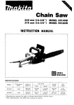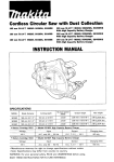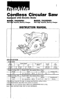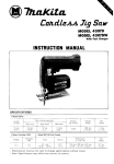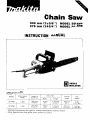
1
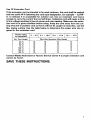
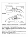
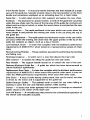
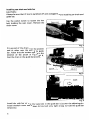
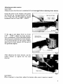
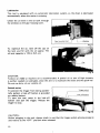
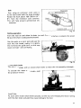
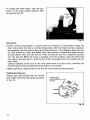
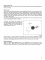
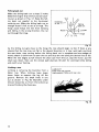
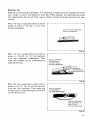
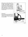
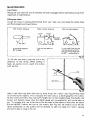
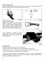
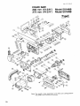
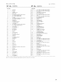
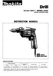
Chain Saw
340 mm (13-3/8")
375 mm (14-3/4")
MODEL 5014NB
MODEL 5016NB
INSTRUCTION MANUAL
I
DOUBLE
INSULATION
I
SPECIFICATIONS
MODEL
5014NB
501 6N8
Chain speed
IFPM)
1,300
1,300
Length of
guide bar
Saw chain
Pitch
Gauge
Overall
length
Net
weight
(13.318")
9.5 mm
1318")
1.27 mm
(0.050")
760 m m
130")
6 kg
(13.2 Ibs)
375 mm
(14-314")
9.5 mm
(318")
1.27 mm
10.050")
795 mm
131-114")
6.3 k g
(13.9 Ibs)
340 mm
IMPORTANT
SAFETY INSTRUCTIONS
WARNING: WHEN USING AN ELECTRIC CHAIN SAW, BASIC
SAFETY PRECAUTIONS SHOULD ALWAYS BE FOLLOWED TO
REDUCE THE RISK OF FIRE, ELECTRIC SHOCK, AND INJURY
TO PERSONS, INCLUDING THE FOLLOWING:
READ ALL INSTRUCTIONS.
1. Keep Work Area Clean
Cluttered areas invite injuries. Do not start cutting until you have a clear work
area, secure footing, and a planned retreat path from the falling tree.
2 . Consider Work Area Environment
Use extreme caution when cutting small size brush and saplings because
the slender material may catch the saw chain and be whipped toward you
or pull you off balance. Do not operate a chain saw in a tree unless specifically trained t o do so. When cutting a limb that is under tension be alert for
spring back so that you will not be struck when the tension in the wood
fibers is released. Don’t expose chain saw t o rain. Don’t use chain saw in
damp or wet locations. Do not use chain saw in presence of flammable
liquids or gases.
3. Guard Against Electric Shock
Prevent body contact with grounded surfaces. For example: metal pipes, wire
fences.
4.Keep Children Away
Do not let visitors contact chain saw or extension cord. All visitors should
be kept away from work area.
5. Store Idle Chain Saw
When not in use, chain saws should be stored in a dry, and high or lockedup place - out of the reach of children. When storing saw, use a scabbard
or carrying case.
6 . Don’t Force Chain Saw
It will do the job better and safer at the rate for which it was intended.
7 . Use Right Tool
Cut wood only. Don‘t use chain saw for purpose not intended - for example
- Don’t use chain saw for cutting plastic, masonry non-wood building
materials.
8 . Dress Properly
Do not wear loose clothing or jewelry. They can get caught in moving parts.
Rubber gloves and non-skid footwear are recommended when working
outdoors. Wear protective hair covering t o contain long hair.
2
9. Use Safety Glasses
Also use safety footwear; snug fitting clothing; protective gloves; hearing
and head protection.
IO. Carrying Saw
Carry the chain saw by the front handle with the saw stopped, finger off
the switch, the guide bar and saw chain t o the rear.
11. Maintain Chain Saw With Care
Inspect chain saw cords periodically and if damaged, have repaired by
authorized service facility. Keep cord clear of the chain and operator at all
times. Never carry saw by the cord or pull it t o disconnect from receptacle.
Keep cord from oil and sharp edges. Inspect extension cords periodically and
replace if damaged. Keep tools sharp and clean for better and safer performance. Follow instructions for lubricating and changing accessories. Keep
handles dry, clean, and free from oil and grease.
12. Disconnect Chain Saw
Disconnect chain saw when not in use, before servicing, and when changing
accessories and attachments, such as saw chain and guard.
13. Outdoor Use Extension Cords
Use only extension cords intended for use outdoors and so marked.
14. Stay Alert
Watch what you are doing. Use common sense. Do not operate chain saw
when you are tired. Keep all parts of the body away from the saw chain when
the motor is operating. Before you start the saw, make sure the saw chain
is not contacting anything.
15. Check Damaged Parts
Before further use of the chain saw, a guard or other part that is damaged
should be carefully checked t o determine that it will operate properly and
perform its intended function. Check for alignment of moving parts, binding
of moving parts, breakage of parts, mounting, and any other conditions that
may affect its operation. A guard or other part that is damaged should be
properly repaired or replaced by an authorized service center unless otherwise indicated elsewhere in this instruction manual. Have defective switches
replaced by authorized service center. Do not use chain saw if switch does
not turn it on and off. Do not operate a chain saw that is damaged, improperly
adjusted, or is not completely and securely assembled. Be sure that the saw
chain stops moving when the trigger is released.
16. Guard Against Kickback
WARNING: KICKBACK may occur when the nose or tip of the guide bar
touches an object, or when the wood closes in and pinches the saw chain
in the cut. Tip contact in some cases may cause a lightning fast reverse
reaction, kicking the guide bar up and back towards the operator. Pinching
the saw chain along the top of the guide bar may push the guide bar rapidly
back towards the operator. Either of these reactions may cause you t o lose
control of the saw which could result in serious injury t o user. The following
precautions should be followed t o minimize kickback.
3
(1) Grip saw firmly. Hold the chain saw firmly with both hands when the
motor is running. Use a firm grip with thumbs and fingers encircling the
chain saw handles.
(2) Do not over reach.
(3) Keep proper footing and balance at all times.
(4) Don't let the nose of the guide bar contact a log, branch, ground, or other
obstruction.
(5)Don't cut above shoulder height.
(6) Use devices such as low kickback chain, chain brakes and special guide
bars that reduce the risks associated with kickback.
(7) Only use replacement bars and chains specified by the manufacturer.
17. Power Supply
Connect chain saw t o correct voltage, that is, be sure that the voltage
supplied is the same as that specified on the nameplate of the tool.
18. Replacement Parts
When servicing use only identical replacement parts.
19. Wear ear protectors during operation.
20. Before making a felling cut, remove dirt, stones, loose bark, nails, staples
and wire from the tree.
21. Secure the log so that it will not roll or move suddenly during operation.
22. AVOID UNINTENTIONAL STARTING. Don't carry plugged-in tool with finger
on switch. Be sure switch is OFF when plugging in.
23. Attention! Do not expose this tool t o rain and pull plug immediately if the
supply cable be damaged or cut.
24. The chain saw must not be left outdoors during rain and it must not be used
when wet.
VOLTAGE WARNING: Before connecting the tool t o a power source (receptacle.
outlet, etc.) be sure the voltage supplied is the same as that specified on the
nameplate of the tool. A power source with voltage greater than that specified
for the tool can result in SERIOUS INJURY t o the user - as well as damage t o
the tool. If in doubt, DO NOT PLUG IN THE TOOL. Using a power source with
voltage less than the nameplate rating is harmful t o the motor.
4
Use Of Extension Cord
If the extension cord is intended t o be used outdoors, the cord shall be marked
with the suffix W-A following the cord type designation, for example - SJTWA, t o indicate it is acceptable for outdoor use. Use an extension cord heavy
enough t o carry the current the tool will draw. Undersize cord will cause a drop
in line voltage resulting in loss of power and over-heating. Make sure the extension cord is i n good condition before using. Keep the cord away from the cutting area and t o position cord so that it will not be caught on branches, and the
like, during cutting. Use the table below t o determine the proper wire size required in the extension cord.
Ampere rating
(on nameplate) 0 -
5.0
Ext. Cord Length
25 Ft.
50 Ft.
75 Ft.
100 Ft.
125 Ft.
150 Ft.
5.1 - 10.0
10.1 - 13.0
13.1 - 15.0
Wire Size (American Wire Gauge)
18
18
18
16
16
16
18
16
16
14
12
12
16
16
14
12
12
12
~
14
14
14
12
12
~
~
Contact Makita Authorized or Factory Service Center if a proper extension cord
cannot be found.
SAVE THESE INSTRUCTIONS.
5
Chain Saw Nomenclature
LEFT SIDE
Front handle
v
Rear handle
/
Trigger switch
RIGHT SIDE
Oil cap
Guide bar nose
\
I
Sprocket
Guide bar
mounting pad
Bar Tip Guard - A n attachment that may be provided on the end of the guide
bar t o prevent the chain at the end of the guide bar from contacting the wood.
Bucking - The process of cross cutting a felled tree or log into lengths.
Chain Brake
-
A device used t o stop the chain saw.
Chain Saw Powerhead
-
A chain saw without the saw chain and guide bar.
Clutch - A mechanism for connecting and disconnecting a driven member t o
and from a rotating source of power.
Drive Sprocket or Sprocket - The toothed part that drives the saw chain.
Felling - The process of cutting down a tree.
Felling Back Cut - The final cut in a tree felling operation made on the opposite
side of the tree from the notching undercut.
Front Handle
saw.
6
- The
support handle located at or toward the front of the chain
Front Handle Guard - A structural barrier between the front handle of a chain
saw and the guide bar, typically located close t o the hand position on the front
handle and sometimes employed as an activating lever for a chain brake.
Guide Bar - A solid railed structure that supports and guides the saw chain.
Kickback - The backward or upward motion, or both of the guide bar occurring
when the saw chain near the nose of the top area of the guide bar contacts any
object such as a log or branch, or when the wood closes in and pinches the saw
chain in the cut.
Kickback, Pinch - The rapid pushback of the saw which can occur when the
wood closes in and pinches the moving saw chain in the cut along the top of
the guide bar.
Kickback, Rotational - The rapid upward and backward motion of the saw which
can occur when the moving saw chain near the upper portion of the tip of the
guide bar contacts an object, such as a log or branch.
Low-Kickback Chain - A chain that complies with the kickback performance
requirements of ANSI B175.1 when tested on a representative sample of chain
saws.
Normal Cutting Position
and felling cuts.
- Those
positions assumed in performing the bucking
Notching Undercut - A notch cut in a tree that directs the tree's fall.
- A system for oiling the guide bar and saw chain.
Rear Handle - The support handle located at or toward the rear of the saw.
Reduced Kickback Guide Bar - A guide bar which has been demonstrated t o
Oiler Control
reduce kickback significantly.
Replacement Saw Chain - A chain that complies with the kickback performance
requirements of ANSI 6175.1 when tested with specific chain saws. It may not
meet the ANSI performance requirements when used with other saws.
Saw Chain - A loop of chain having cutting teeth, that cut the wood, and that
is driven by the motor and is supported by the guide bar.
Spiked Bumper (Spike) - The pointed tooth or teeth for use when felling or
bucking t o pivot the saw and maintain position while sawing.
Switch - A device that when operated will complete or interrupt an electrical
power circuit t o the motor of the chain saw.
Lock-Off Button - A movable stop that prevents the unintentional operation of
the switch until manually actuated.
Installing saw chain and guide bar
CAUTION :
Always be sure that the tool is switched off and unplugged before installing saw chain and
guide bar
Use the socket wrench to loosen the hex
bolt holding the chain cover. Remove the
chain cover.
1
Fig. 2
Fit one end of the chain over the sprocket
and the other over the end of the guide
bar. Notice that the cutters must be in the
direction of the arrow in Fig. 3 and 4.
Keep the chain in the guide bar grooves.
Install the guide bar so that the lower hole in the guide bar is just over the adjusting pin.
Install the chain cover and tighten the hex bolt only tight enough to hold the guide bar
temporarily.
8
Adjusting saw chain tension
CAUTION :
Always be sure that the tool is switched off and unplugged before adjusting chain tension.
Grasp the chain in the middle of the guide
bar and lift up. The gap between the side
link of the chain and the guide bar should
be about 3 mm to 4 mm (1/8" - 5/32").
Fig. 5
I f the gap is not about 3 m m to 4 m m
(1/8" - 5/32"), adjust the chain tension.
Use a screwdriver to turn the chain tension
adjusting screw clockwise for more tension,
or counterclockwise for less tension. When
adjusting the chain tension, lift the end of
the guide bar slightly.
Fig. 6
After adjusting the chain tension, use the
socket wrench to tighten the hex bolt
securely.
I
Fig. 7
CAUTION :
When breaking in a new chain, adjust the tenision often, since it tends to 'stretch'.
9
Lubrication
This tool i s equipped with an automatic lubrication system, so the chain is lubricated
automatically when the motor is running.
I
Gear housing cover
\
I
Window
To replenish the oil, take off the cap on
the tank and fill with the oil supply. The
oil tank capacity i s 170 cc (5.5 oz).
CAUTION :
Turbine oil #200 or machine oil is recommended. A special oil or one of high viscosity
i s neither needed nor advisable, since the aim is to lubricate the chain and the guide bar.
Do not use dirty oil nor volatile oil.
Switch action
To prevent the trigger from being accidentally pulled, a lock-off button is provided
as a safety feature.
To start the tool, press in the lock-off
button and pull the trigger. Release the
trigger to stop.
I _ r--- I
Trigger switch
Lock-off button
CAUTION :
Before plugging in the tool, always check to see that the trigger switch actuates properly
and returns to the "OFF" position when released.
10
Hook
When using an extension cord, secure it
to the tool’s cord with the hook provided.
Attach the hook about 100-200 mm (4”8”) from the extension cord connector.
This will help prevent unintentional disconnection.
Power cord
Extension cord
Fig.
Cutting operation
Turn the tool on and allow the chain to reach full speed before it contacts the wood.
Be sure the chain is adequately lubricated.
Use the spike as a pivot point and ease the
tool into the wood, rocking it in gently.
Do not force the guide bar in, as this may
cause overload -and overheating.
Instant chain brake
This tool is equipped with an instant chain brake to reduce the risk caused by kickback.
To actuate the instant chain brake, push
the protector forward.
Fig. 13
CAUTION :
As soon as the instant chain brake actuates, turn the tool off. Keeping the motor running
with the chain brake actuated may cause damage to the tool.
11
To release the chain brake, reset the protector to the exact original position after
turning the tool off.
Fig. 14
WARNING:
0 Under normal circumstances, it should never be necessary to intentionally release the
chain brake while the tool i s running. Occasionally, after the brake has been actuated,
the protector may not reset t o the exact original position. If this happens, place the tool
on a flat surface in a clear area (away from other persons or objects that might contact
the saw chain). Then turn the tool on. After running the tool for a couple of seconds,
turn the tool off. While the motor i s coasting, reset the protector with the same hand
you used to turn the tool on. Hold the tool firmly by grasping the front handle with the
other hand.
Careless handling of the tool a t this time could result in serious injury, therefore use
extreme caution when resetting the chain brake in this manner.
0
Before operation, always check to see that the chain brake actuates properly.
Holding the chain saw
Always grip each handle with the thumb
and fingers encircling the handle as shown
in Fig. 15.
12
I
Use this grip
thumb belowhandle
Using the chain saw
Always be sure of your footing and hold the chain saw firmly with both hands while the
motor is running.
Felling a tree
When bucking and felling operations are being performed by two or more persons, a t the
same time, the felling operation should be separated from the bucking operation by a
distance of a t least twice the height of the tree being felled. Trees should not be felled in
a manner that would endanger any person, strike any utility line or cause any property
damage. I f the tree does make contact with any utility line, the utility company should
be notified immediately.
The chain saw operator should keep on the uphill side of the terrain as the tree i s likely
to roll or slide downhill after it is felled.
A retreat path should be planned and
cleared as necessary before cuts are started.
The retreat path should extend back and
diagonally to the rear of the expected line
of fall as shown in Fig. 16.
I
Treat
Direct Ion
of fall
-_--
I
Fig. 1
Before felling is started, consider the natural lean of the tree, the location of larger
branches and the wind direction to judge which way the tree will fall. Remove dirt,stones,
loose bark, nails, staples, and wire from the tree where felling cuts are to be made.
Notching undercut
Make the notch 1/3 the diameter of the tree, perpendicular to the direction of fall as
shown in Fig. 17. Make the lower horizontal notching cut first. This will help to avoid
pinching of either the saw chain or the guide bar when the second notch i s being made.
13
Felling back cut
Make the felling back cut a t least 2 inches
(50.8 mm) higher than the horizontal notching cut as shown in Fig. 17. Keep the felling back cut parallel to the horizontal
notching cut. Make the felling back cut so
enough wood i s left to act as a hinge. The
hinge wood keeps the tree from twisting
and falling in the wrong direction. Do not
cut through the hinge.
-
Direction
of fall
back cut
Notch
- __ ---7
1\ \
\\\
2 inches
Hinge
1
Fig. 1
As the felling cut gets close to the hinge the tree should begin to fall. If there i s any
chance that the tree may not fall in the desired direction or i t may rock back and bind
the saw chain, stop cutting before the felling back cut is complete and use wedges of
wood, plastic or aluminum to open the cut and drop the tree along the desired line of fall.
When the tree begins to fall remove the chain saw from the cut, stop the motor, put the
chain saw down, then use the retreat path planned. Be alert for overhead limbs falling
and watch your footing.
Limbing a tree
Limbing is removing the branches from a
fallen tree. When limbing, leave larger
LIMB CUT
Keep work off ground
Leave support limbs until log i s cut
lower limbs to support the log off the
ground. Remove the small limbs in one
cut as shown in Fig. 18. Branches under
tension should be cut from the bottom up
to avoid binding the chain saw.
Fig. 1
14
Bucking a log
Bucking is cutting a log into lengths. It is important to make sure your footing is firm and
your weight i s evenly distributed on both feet. When possible, the log should be raised
and supported by the use of limbs, logs or chocks. Follow the simple directions for easy
cutting.
When the log i s supported along its entire
length as shown in Fig. 19, it is cut from
the top (overbuck).
I
Cut from top (overbuck)
avoid cutting earth
When the log is supported on one end, as
shown in Fig. 20, cut 1/3 the diameter
from the underside (underbuck). Then
make the finished cut by overbucking to
meet the first cut.
(2/3 diameter)
to meet 1st cut
( t o avoid pinching)
Fig. 21
When the log i s supported on both ends, as
shown in Fig. 21, cut 1/3 of that diameter
from the top overbuck. Then make the
finished cut by underbucking the lower 2/3
to meet the first cut.
I
1st cut overbuck
(1/3 diameter)
(to avoid splintering)
.
-
2nd cut underbuck
(2/3 diameter) t o
meet 1st cut
( t o avoid pinching)
I
Fig. 2
15
When bucking on a slope, always stand on
the uphill side of the log, as shown in Fig.
22. When ”cutting through”, t o maintain
complete control, release the cutting pressure near the end of the cut without relaxing your grip on the chain saw handles.
Don‘t l e t the chain contact the ground.
After completing the cut, wait for the saw
chain t o stop before you move the chain
saw. Always stop the motor before moving
from tree to tree.
1
log may roll.
Fig. 2:
Carrying tool
Carry the tool by the front handle with the
tool turned off, finger off the switch, the
guide bar and the saw chain t o the rear.
Use the scabbard to cover the guide bar
and the saw chain.
I
16
Fig. 2
MAINTENANCE
CAUTION :
Always be sure that the tool is switched off and unplugged before attempting t o perform
inspection or maintenance.
Filling saw chain
To get the most in cutting performance from your tool, you must keep the cutter sharp
and filed properly as shown below.
TOP PLATE ANGLE
SIDE PLATE ANGLE
Cutter
A top plate angle of
30' is ideal.
Raker
,
File the side plate to
85".
TOP FILING ANGLE
/
If you have filed the top
and side plate correctly
the top filling angle will
be 60" -automatically.
Fig. 2r
To file the saw chain, push the file in the
direction of the arrow. When pulling it
back, be careful not to touch the cutters
with the file.
Saw chain
Fig. 2!
After a saw chain has been filed two or three times, the "raker" (see Fig. 24) may need
to be filed down slightly. This is because the raker acts as a depth gauge for the cutters.
As the cutters are filed, they lose some height due to their angled shape. Eventually, the
cutters will become lower than the depth gauge and consequently, will not be able to
cut. To remedy this, use a flat file to file the tops of the rakers so that they are about
0.5 mm (0.025") below the tips of the cutters (see Fig. 24). Be careful not to file the
rakers excessively or the cutters will be allowed to take too large of a "bite", causing
the tool to stall or snag in the cut.
17
Removing chip buildup
Chips and sawdust will build up in the guide bar groove and oil hole, clogging them and
impairing oil flow. Remove the guide bar and clean them out.
Clean out
Guide bar
Fig. 2
Replacing carbon brushes
Remove and check the carbon brushes
regularly. Replace when they wear down
to the limit mark. Keep the carbon brushes
clean and free to slip in the holders. Both
carbon brushes should be replaced a t the
same time. Use only Makita carbon brushes.
/
Limit mark
Use a screwdriver to remove the brush
holder caps. Take out the worn carbon
brushes, insert the new ones and secure the
brush holder caps.
Storing the tool
Before storing the tool, be sure td do the following:
Remove the chain cover. Remove any chips and sawdust from the tool.
0
0
Install the chain cover. Turn the tool on and depress the oil button 4 or 5 times.
.Cover the saw chain and the guide bar with the scabbard.
To maintain product SAFETY and RELIABILITY, repairs, any other maintenance or
adjustment should be performed by Makita Authorized or Factory Service Centers,
always using Makita replacement parts.
18
ACCESSORIES
CAUTION :
These accessories or attachments are recommended for use with your Makita tool specified in this
manual. The use of any other accessories or attachments might present a risk of injury t o persons. The
accessories or attachments should be used only in the proper and intended manner.
Socket wrench 13
Part No. 78221 2-4
0
Scabbard
Part No. 414593-5
Saw chain
Part No. 713014-7 (For 5014NB)
Part No. 713015-5 (For 5016NB)
Screwdriver
Part No. 783001-0
File
Part No. 744003- 1
Oil supply
Cap for oil supply
Part No. 24201 2-9
Part No. 181117-9
Hook
Part No. 158024- 1
19
Aq-25438
US
CHAIN SAW
340 mm (13-318") Model 5014NB
375 mm (14-3/47 Model 5016NB
Note: The switch, noise suppressor and other part configurations
may differ from country to country.
20
MODEL 5014NB 5016NB
D:$
lo
11
::
14
15
1
1;
1
1
2
19
1
20
21
22
Guide Bar
54
1
Protector
Packmg
Supporter Plate
Brake Lever
Pan Head Screw M5x16 IWtth W a r h e i l
Hex Socket Head Bo11 M 6
Hex Socket Head Bolt M 6
Packing
Pan Head Screw M 5 x l Z (With Warherl
Fiat Head Screw M 5 x 4 0
Adlust Pin
Steel Ball 5 6
Compresslo" sprrng 4
Tension Spring 6
cover Plate
Pan Head Screw M 4 x 1 0 (With Washer1
Hex Flange Head Bolt Max17
Chain Cover
Hex Nut M 8 1 3
Flat Washer 8
55
56
57
6
Dust c o v e r
23
24
Dust Seal 30
25
Sprocket
Pin 6
Clufch Piessure
26
27
28
1
1
33
34
35
1
36
37
38
39
40
41
42
43
44
45
46
47
48
49
1
1
Slop Ring E 3
Compreaslon spring 5
Norrle R
0 Ring 8
Compresslo" spring 3
Steel Ball 3 5
0 Ring 3
Ca*,"g
Fl f ~ r
0 Ring 9
Nozzle A
2
cap
011 Vessel
Check Valve
Tube 3
Pan Head Screw M4x12 i W i t h Wdaherl
ORng3
1
Gear Housing
3
Plunger
50
Pin 6
Cha n Catcher
Clutch C a m
Flat Washer 10
51
Ring 5
52
53
$tD
DESCRIPTION
16
17
29
30
31
32
Aug
1
1
Thin Washer 6
Fldf Warher 5
58
59
60
61
62
63
1
I
1
2
1
2
1
1
-
25-'88 US
DESCRIPTION
Pan Head Screw M 5 x 1 6 (With Washerl
Pan Head Screw M 4 x 1 0 iWith Washerl
Slider Plate
Hex Sockel Head Bolt M 6
Gear Housing Cover
Pan Head Screw M 5 x 2 0 IWith Washerl
Grip
Pan Head Screw M5x16 IWith Washerl
Ball Bearing 6001LLB
Flat Washer 12
Slider
68
1
69
1
70
71
72
73
74
1
75
76
1
Flat Washer 16
Helical Gear 53
Set Screw MBx16
Plate
Compression Spring 4
Woodruff Key 5
Spindle
Flat Washer 17
Ball Bearing 6003LLB
Ball Bearing 6201LLB
Fan 97
ARMATURE ASSEMBLY
IWith ltem 74
781
lniulation Washer
Ball Bearing 6200LR
Hex Bolt M5x70 (With Washerl
Baffle Plate
FIELD ASSEMBLY
Motor Housing
Rivet 0 - 5
Name Plafe
Pan Head Screw M5xZO IWlIh Washeri
Pan Head Screw M 5 x 5 0 IWith Warherl
Carbon Brush
Brush Holder Cap
Pan Head Screw M 4 x 6 (With Washeri
Switch
Rubber Pin 4
Handle Set (With ltem l O 0 i
Pan Head Screw M 5 x l R IWifh Washer1
Rubber Pin 4
Cord Guard
Cord
Strain Relief
Pan Head Screw M4x18 W t h W a r h v r l
Handle Set (With ltem 921
Pan Head Screw M4x28 IWith Washerl
Safety cover
Pan Head Screw M 5 x 2 2 IWith Washeri
~
77
78
79
80
81
82
83
84
85
86
87
88
89
90
91
92
93
94
96
97
98
99
100
101
102
103
900
4
1
1
2
2
1
I
L e a l spring
Nole The S w i t c h and other part speC8frCdtlOnS m a y differ from country t o c o u n t r y
21
MAKllA LIMITEDONE YEAR WARRANTY
Warranty Policy
Every Makita tool is thoroughly inspected and tested before leaving the factory. It is warranted to
be free of defects from workmanship and materials for the period of ONE YEAR from the date of
original purchase. Should any trouble develop during this one-yeax period, return the COMPLETE
tool, freight prepaid, to one of Malcita’s Factory or Authorized Service Centers. If inspection shows
the trouble is caused by defective workmanship or material, Makita will repair (or at our option,
replace) without charge.
This Warranty does not apply where:
repam have been made or attempted by others:
repam are required because of normal wear and tear
The tool has been abused. misused or Improperly
mamtruned.
. .
alterations have been made to the tool.
IN NO EVENT SHALL MAKITA BE LIABLE FOR ANY INDIRECT, INCLDENTAL OR CONSEOIJENTIAL DAMAGES FROM THE SALE OR USE O F THE PRODUCT. THIS DISCLAIMER
APFLIEs BOTH DURING AND AFTER THE TERM OF THIS WARRANTY.
MAKlTA DISCLAIMS LIABILITY FOR ANY IMPLIED WARRANTIES, INCLUDING IMPLIED
WARRANTIES OF “MERCHANTABILITY” AND “FITNESS FOR A SPECIFIC PURPOSE,”
AFTER THE ONE-YEAR TERM O F THIS WARRANTY.
This Warranty gives you specific legal rights, and you may also have other rights which vary from
state to state. Some states do not allow the exclusion or limitation of incidental or consequential
damages, so the above limitation or exclusion may not apply t o you. Some states do not allow
limitation on how long an implied warranty lasts, so the above limitation may not apply to you.
Makita Corporation
3-11-8,
Surniyoshi-cho,
Anjo, Aichi 446 Japan
883465 - 061
PRINTED IN JAPAN
1991 - 11 - N