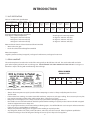
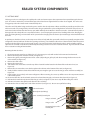
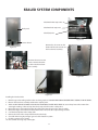
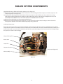
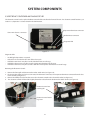
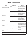
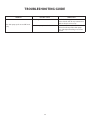
1
ICE MAker
Service manual
Models
RF15I
1
CONTENTS
1. Introduction
1.1 Unit Specifications
1.2 Serial Nameplate
1.3 Before Servicing
1.4 After Servicing
1.5 Basic Refrigeration Tools
1.6 Installation
1.7 Electrical Requirements
1.8 Water Requirements
1.9 Gravity Drain
1.10 Drain Pump
1.11 Operation in “ON” Position
1.12 Operation in “CLEAN” Position
2. Sealed System
2.1 Introduction
2.2 Low Side Leaks
2.3 High Side Leaks
2.4 Restricted Capillary Tube
2.5 Access Valves
2.6 Pressure and Temperature
2.7 Re-charging
3. Sealed System Components
3.1 Hot Gas Valve
3.2 Evaporator
3.3 Compressor
3.4 Condenser
4. Valves
4.1 Drain Valve
4.2 Water Valve
5. System Components
5.1 Condenser Fan
5.2 Thermistors
5.3 Electronic Controller and Diagnostic LED
5.4 Cutter-Grid Transformer
6. Interior Components
6.1 Cutter-Grid
6.2 Reservoir
6.3 Circulation Pump
7. Wiring
7.1 Wiring Diagram/Connections
8. Ordering Parts
9. Ice Maker Storage - Outdoor Model
10. Restarting the Ice Maker
11. Troubleshooting Guide
12. Warranty
1
2
2
2
3
3
3
3
4
4
5
5
6
7
7
7
7
8
8
9
10
12
14
15
16
17
18
18
21
22
23
23
25
26
27
28
29
30
36
Introduction
1.1 Unit Specifications
Table A: Ice Maker Unit Specifications
Exterior Cabinet Dimensions
(in)
Height
Width
Depth
34-1/4
14-7/8
21-1/4
Shipping
Weight
(lbs)
Electrical
Requirements
100
120VAC/
60 Hz
Power
Cord
Length
(ft)
Compressor
R-134a
Refrigerant
Charge
(oz)
Equalized
Pressure
System
Refrigerant
Control
Temperature
Control
Condenser
Fan Motor
Controller
UL
7
Piston type
5
72 psi at 77
degrees F
Capillary
tube
Electronic Control
with thermistor
input
2.3 W 1300
RPM
Electronic solid
state sequence
timer
SA7230
Average Icemaking Capacity per 24 hours:
At 50 degrees F water temperature:
70 degrees F ambient: 35 lb/day
80 degrees F ambient: 30 lb/day
90 degrees F ambient: 23 lb/day
At 70 degrees F water temperature:
70 degrees F ambient: 32 lb/day
80 degrees F ambient: 27 lb/day
90 degrees F ambient: 20 lb/day
Water and Drain Controls: Solenoid activated. Flow Controlled.
• Water valve: 0.25 gpm
• Drain valve: External tee fitting flow controlled
Water Consumption:
16 gal/day continuous duty (not typical), 70 degrees F ambient max., 50 degrees F water max.
1.2 Serial Nameplate
The serial nameplate is located on the inside of the unit, typically on the left liner side wall. The serial number will need to be
given when inquiring about the unit or ordering parts. DO NOT REMOVE THE SERIAL NAMEPLATE FROM THE UNIT. See Figure 1.1
below for a sample serial tag with manufacturing date code logic.
SERIAL NUMBER:
20080313119R
1.3 Before Servicing
•
•
•
•
•
•
•
•
2008
03
13
119
R
year
month
day
No. built that
day
Refrigeration
Figure 1.1
Always disconnect power to any DCS product before attempting to service it. Always verify that power has been
disconnected.
If the unit has been running, use caution around the condenser, compressor, and copper tubing. These areas may be very hot.
Use caution around the condenser fins and baseplate edges. These areas are sharp.
Refrigerant is under high pressure. Always evacuate any system before attempting to work on it.
Reasonable care and safe work methods should be practiced when working on any DCS product. Never work with energized
electrical equipment in wet or damp areas.
Use an appropriate work area and location when performing repairs. You will find that it is easier to repair undercounter units
if they are set on a raised platform or workbench.
Always wear protective safety glasses and gloves when working on any DCS product.
Any refrigerant, whether CFC, HCFC, or HFC (R-12, R-22, or R-134a), must be recovered. Federal regulations prohibit the
intentional venting or release of refrigerants during the service repair or disposal of an appliance.
2
Introduction
1.4 After Servicing
After servicing the unit, whether at a site or service center, check the following:
•
•
•
MAKE CERTAIN THERE ARE NO LEAKS IN THE DRAIN OR WATER LINES. Check the water line, water valve, drain valve, and drain
tubing for leaks.
Make certain the Ice Maker functions properly by observing ice production and ice harvest cycles. Check for hollow ice slabs
or ice slabs that will not release.
Make certain the bin thermostat will turn the unit off. The best way to check this is to let the Ice Maker bin fill with ice. However, if time is restricted then use several ice cubes and place them on the bin thermostat’s capillary tube sleeve located on
the side of the ice bin. The unit should shut down within a few minutes. After removing the ice, the unit should start at least
five minutes later.
1.5 Basic Refrigeration Tools
The following list contains SOME of the tools required for basic refrigeration repairs:
1.
2.
3.
4.
5.
6.
7.
8.
9.
10.
11.
12.
13.
14.
15.
Hoses with R-134a couplers (must meet standards for handling R-134a refrigerant)
Approved and certified recovery system for R-134a
Manifold gage set for R-134a
Charging cylinder with R-134a
Weight scale (preferably in ounces to the nearest tenth of an ounce)
Access valves
Small and large tubing cutter
Brazing torch
Swaging tools
Multimeter
Leak detection equipment for detection of R-134a
Standard hand tools (assorted Phillips and standard screwdrivers, sockets, allen wrenches, adjustable wrenches, etc.)
Rivet gun and assorted rivets
Drill motor and assorted metal drills
Vacuum pump
1.6 Installation
•
•
•
•
•
Unit can be installed freestanding or enclosed. The front of the unit must be unobstructed for proper air circulation and operation at all times.
Area should be ventilated with a temperature above 55 degrees F and below 90 degrees F for proper operation.
Unit can be installed outdoors and away from the elements of nature. As the unit is rated for outdoor, it has added electrical
protection and is UL tested and recognized for outdoor use.
UNIT MUST BE ON A LEVEL SURFACE capable of supporting the loaded weight of the unit.
For additional information, refer to the Owner’s Guide supplied with the unit.
1.7 Electrical Requirements
•
•
WARNING
ELECTRICAL SHOCK HAZARD
Failure to follow these requirements could result in personal injury,
electrical shock, or fire.
115 VAC, 60 Hz., single phase power is needed
Use an outlet with a 15 amp circuit. A ground fault circuit interrupter (GFI) electrical receptacle is to be used to supply electrical power to the Ice Maker.
3
Introduction
•
•
•
Properly grounded outlet is required for this unit.
It is recommended or your building code may require that a single circuit GFCI receptacle or breaker be used for this unit only.
DO NOT USE AN EXTENSION CORD.
Outdoor models must use a GFCI receptacle.
1.8 Water Requirements
•
•
•
•
•
•
Use supplied water line fitting for water connection to the rear of the unit.
Use cold, potable water supply only with pressure between 20 to 120 psi.
Use 1/4 inch OD soft copper tubing. Plastic tubing can be used, but may leak with age.
Use 1/4 inch saddle shut-off valve. Check to make sure valve complies with local codes. DO NOT USE SELF-PIERCING SADDLE
VALVE OR LESS THAN 1/4 INCH SADDLE VALVE AS WATER FLOW WILL BE RESTRICTED.
A quality system water filter or local water filter is recommended. A quality filter can remove particles as well as remove unpleasant taste and odors from water.
Softened water is not recommended. Depending on mineral concentrations, this can produce cloudy white cubes that may
stick together.
The above materials can be found at most local plumbing supply stores or hardware stores. Use fittings that are specified for
potable water. Follow the manufacturer’s installation instructions for water valves and water line hook-ups. Make certain the
waterline and the valve do not leak prior to enclosing cabinet.
1.9 Gravity Drain
NOTICE
OBSERVE AND FOLLOW ALL LOCAL AND STATE CODES WHEN INSTALLING ICE MAKER.
NOTICE
A DRAIN PUMP MUST BE USED FOR ICE MAKER DRAIN.
The drain fitting from the Ice Maker is for 5/8 inch OD tubing. This tubing can be routed to a gravity drain in the area shown in
Figure 1.2 or to a remote gravity drain that is located below the Ice Maker. Be sure to check your local codes. Slope any long horizontal runs according to code to remote gravity drain for proper drainage. An air gap may be necessary for horizontal runs over
four feet. Use thick wall tubing that will not kink easily when the Ice Maker is installed. PROPER ROUTING, SLOPING, AND SIZE OF
DRAIN LINE IS IMPORTANT ESPECIALLY IF USING FLEXIBLE TUBING OR POOR ICE PRODUCTION WILL RESULT.
If installing a standoff gravity drain, use Figure 1.2 for location. Standpipe can be up to three inches high above the floor. Route
the tubing from the Ice Maker into drain pipe. See the Owner’s Guide for additional drain information.
It may be necessary in some installations to wrap drain tubing with wrap-type insulation to prevent condensation on the drain
tube. CONDENSATION CAN FORM ON THE DRAIN TUBING AND CAUSE SURROUNDING WATER DAMAGE.
Figure 1.2
4
Introduction
1.10 Drain Pump
DCS Drain Pump can be used to drain water when a gravity drain is not practical. Refer to drain pump instructions supplied with
the drain pump for installation.
As with the gravity drain, it may be necessary to wrap the drain tubing from the Ice Maker to the inlet of the drain pump with
wrap-type insulation. CONDENSATION CAN FORM ON THE DRAIN TUBING AND CAUSE SURROUNDING WATER DAMAGE.
1.11 Operation - Selector Switch is in the “ON” Position
IMPORTANT: The assumptions before proceeding are that water is supplied to the Ice Maker (see Section 1.8, Water Requirements), there is proper electrical power to the Ice Maker (see Section 1.7, Electrical Requirements), the drain is properly plumbed
or the drain pump is operating properly, and both bin and evaporator thermistors are not defective.
Input power must be applied at all times for proper operation. Any interrupt will lockout the compressor for no less than seven
minutes and up to nine minutes and restart the mode of operation. Figure 1.3 below is the Timing Diagram/Operation for the
electronic control.
*
Figure 1.3
Upon setting the switch to the “ON” position, the water solenoid will energize for one and a half minutes and then de-energize.
When the bin thermistor senses temperature at or above the “start ice” setpoint, and the evaporator thermistor senses temperature at or above the “production” setpoint, the production cycle will begin. The circulation pump, condenser fan, and compressor
relay will energize. When the evaporator thermistor senses temperature at or below the “harvest” setpoint, the harvest cycle will
begin. The circulation pump and condenser fan outputs will be de-energized and the hot gas solenoid and the drain solenoid will
energize. The drain solenoid will remain energized for 45 seconds and then de-energize, after which the water solenoid will energize for two minutes and then de-energize. Loads will remain in this state until the evaporator thermistor temperature rises to
the “production” setpoint. Once the evaporator thermistor temperature is at or above the “production” setpoint, a new production
cycle will begin. If at any time the bin thermistor senses a temperature at or below the “stop ice” setpoint, any production or
5
Introduction
harvest cycle in process will continue until the harvest cycle is complete. Once complete, all loads will de-energize and remain so
until the bin thermistor senses a temperature at or above the “start production” setpoint. A new production cycle will then begin.
During the first production cycle only (the switch was previously in the “OFF” or “CLEAN” position), the evaporator thermistor
temperature will be ignored until the circulation pump has run for two minutes. During all harvest cycles, the evaporator thermistor temperature cannot terminate the harvest cycle until the water solenoid is de-energized. The grid cutter output will always be
energized during the harvest cycle, and for the first 35 minutes into the production cycle.
If during any production or harvest cycle, the selector switch is put into the “CLEAN” position, any cycle in process will be immediately terminated and a clean cycle will occur. The unit will then repeat the entire above cycle.
If during any production or harvest cycle, the selector switch is put into the “OFF” position, the cycle in process will be stopped and
all loads will de-energize and remain so as long as the selector switch remains in the “OFF” position.
If during any production or harvest cycle, the selector switch is taken out of the “ON” position, a lockout will be started during
which the compressor relay will not re-energize regardless of a switch position.
If during any production or harvest cycle, there is a power loss/interruption of greater than 25 milliseconds, a lockout delay will
begin and the compressor relay will not re-energize upon reapplication of power until the lockout delay is complete. The lockout
delay begins with the loss of power and is unaffected by duration of power loss. All other loads will operate normally during the
lockout.
The setpoints are as follows:
• Stop ice: 35.0 degrees F +/- 2 degrees F
• Start ice: 43.0 degrees F +/- 2 degrees F
• Harvest: 11.0 degrees F +/- 2 degrees F
• Production: 45.0 degrees F +/- 2 degrees F
• Setpoint versus Temperature and Voltage (120VAC): +/- 3 degrees F
1.12 Operation - Selector Switch is in the “CLEAN” Position
IMPORTANT: The assumptions before proceeding are that water is supplied to the Ice Maker (see Section 1.8, Water Requirements), there is proper electrical power to the Ice Maker (see Section 1.7, Electrical Requirements), the drain is properly plumbed
or the drain pump is operating properly, and both bin and evaporator thermistors are not defective. The refrigeration system
components, compressor, condenser fan, and hot gas valve, are never on in the clean cycle.
Upon setting the selector switch to the “CLEAN” position during the production or harvest cycle, the clean cycle will immediately
start, terminating the harvest or production cycle. Refer to the Timing/Operation Diagram in Figure 1.3. The following sequence
will now occur:
1. LED indicator on the control will light for 10 seconds upon the start of the clean cycle. See Section 5.3, Electronic Controller,
for LED location.
2. The water solenoid will energize for three minutes and then de-energize. The circulation pump will now energize.
3. After 30 minutes, the circulation pump will de-energize and the drain solenoid will energize.
4. After 75 seconds, the drain solenoid will de-energize and the water solenoid will energize.
5. After three minutes, the water solenoid will de-energize and the circulation pump will energize.
6. After 10 minutes, the circulation pump will de-energize and the drain valve will energize.
7. After 75 seconds, the drain solenoid will de-energize. The clean cycle is now complete.
All loads will remain off as long as the selector switch remains in the “CLEAN” position and the power is not removed and reapplied.
If at any time during a clean cycle the selector switch is moved from the “CLEAN” position, all loads except the drain solenoid will
de-energize (this includes the “OFF” position). The drain solenoid will energize for 75 seconds and then de-energize. The unit will
now operate normally according to whether it is in the “OFF” or “ON” position.1.
6
Sealed System
2.1 Introduction
The following should always be practiced with any sealed system that has been opened. ONLY OPEN THE SEALED SYSTEM AS
A LAST RESORT AND AS A FINAL DIAGNOSIS. Always check other areas of operation such as wiring, water supply, drain setup,
proper air flow, etc. before opening up the sealed system. Many times these areas can resemble sealed system problems. The
diagnosis of a sealed system can be determined by accurate pressure and temperature measurements.
1. Use a leak detection system that will detect R-134a refrigerant. Leaks need to be found on any leaking system BEFORE the
repair takes place.
2. The drier must be replaced anytime the sealed system is opened. Always use a DCS drier. Failure to do so may cause repeated
system failure in the future.
3. Limit time the system is opened. DO NOT EXPOSE THE OPEN SYSTEM FOR MORE THAN 15 MINUTES. This will prevent a sealed
system failure. Leave replacement parts sealed and/or pressurized until ready to install.
4. The compressor must be replaced if there is a low side leak. Moisture has been drawn into the system if the unit has been
running for an extended period of time. Be sure to flush the system with dry nitrogen gas and evacuate to 50 microns before
re-charging (see Section 2.2, Low Side Leaks).
5. A new evaporator assembly must be ordered if the capillary tube is found to be plugged or severely restricted. Restrictions
cannot be flushed out.
6. Be sure to purge the system after final brazing. This will flush out any air or moisture that may have entered the system before
being absorbed into the refrigerant oil.
IMPORTANT
Testing of the electrical system, defrost system, controls, and air flow should be performed before entering any sealed system.
What may first appear to be a system component failure may be only a simple control, air flow, electrical, or defrost system
problem.
2.2 Low Side leaks
Low side leaks consist of a break in the system at the evaporator, low side (suction) return line, or accumulator. If a leak is found in
any of these areas, moisture has probably entered the system. The compressor and drier will have to be replaced and the system
will need to be flushed thoroughly with nitrogen gas and evacuated to 50 microns before re-charging.
2.3 High Side Leaks
High side leaks consist of a break in the system at the condenser, high side tubing, drier, or capillary tube. If a leak is found in any
of these areas, the system can be flushed with nitrogen gas, evacuated to 50 microns, and re-charged.
2.4 Restricted Capillary Tube
Moisture or other contaminants that enter the system can cause deposits in the system. These deposits will usually collect in the
capillary tube and form a restriction that cannot be completely removed by flushing. If the capillary tube is found to be restricted,
the evaporator, compressor, condenser, and drier should all be replaced.
7
Sealed System
2.5 Access Valves
A temporary access valve can be used to service or evaluate the system. The access valve can be installed on the compressor’s
process tube (this will also be a low pressure side). Be sure to cap off access valve while servicing. This will prevent contamination
of the system and/or refrigerant from leaking. AFTER SERVICING, THE ACCESS VALVE SHOULD BE REMOVED. A pinch-off tool can
be used to close the system to remove the access valve and then braze the hole for the access valve to seal the system. Be sure to
leak check after brazing.
2.6 Pressure and Temperature
There are a couple of ways to measure temperature of the evaporator plate:
1. Use a thermocouple to measure the temperature of the evaporator plate. The thermocouple must be secured to the evaporator when taking the measurement. The best and most accurate location for the thermocouple end is where the thermistor is
secured to the evaporator. Allow anywhere from three to six degrees F of variation in measured temperatures if you measure
on the plate because of the thermal conductivity of the thermistor body in comparision to the thermocouple.
2. If it has been determined that there is proper contact between the thermistor and evaporator plate, the thermistor resistance
value can be corresponded to the temperature (see Table C in Section 5.2, Thermistors, for values).
3. If it has been determined that there is proper contact between the thermistor and the evaporator plate, the voltage at the
thermistor terminals can be read. The voltage can be read while the unit is running by attaching test leads to thermistor terminals at the electronic control. The temperature to switch into harvest cycle is 11 degrees F and the corresponding voltage
is 3.77V. The temperature to switch into the production cycle is 45 degrees F and the corresponding voltage is 2.88V. Slight
variations in actual measurements can occur due to input voltage variations.
NOTE: THE TEMPERATURE AND PRESSURE READINGS MUST BE TAKEN WITH THE UNIT ON AND WATER FLOWING OVER THE EVAPORATOR PLATE (IN THE PRODUCTION CYCLE). USE GAGE PRESSURE READINGS FROM THE COMPRESSOR’S PROCESS TUBE (LOW
SIDE) ACCESS VALVE.
Table B: Refrigeration Temperature-Pressure Chart for R-134a
Degrees F
Pressure (psi) R-134a
Degrees F
Pressure (psi) R-134a
-12
1.1
36
31.3
-8
2.8
38
33.2
-4
4.5
40
35.1
0
6.5
42
37.0
2
7.5
44
39.1
4
8.5
46
41.1
6
9.6
48
43.3
8
10.8
50
45.5
10
12.0
52
47.7
12
13.1
56
52.3
14
14.4
60
57.5
16
15.7
64
62.7
18
17.0
68
68.3
20
18.4
72
74.2
22
19.9
76
80.3
24
21.4
80
86.8
26
22.9
84
93.6
28
24.5
88
100.7
30
26.1
92
108.2
32
27.8
96
116.1
34
29.5
100
124.3
8
Sealed System
During production cycle, low side pressures will vary anywhere from 140 psi to 2 psi, depending at what point measurements are
taken. High side pressures can range from 481 psi to 25 psi also depending at what point measurements are taken.
In evaluating this system, the best point to determine if pressures are correct is at the end of the production cycle. This is the
point where there is a thick slab formed on the evaporator and the evaporator thermostat is near cut-out temperature. Using
Table B, convert temperature to a corresponding pressure.
If low side pressure is below pressure in Table B, check for the following:
1. A system leak
2. Capillary tube is restricted
3. Insufficient compressor (does not pump properly)
If low side pressure is above pressure in Table B, check for the following:
1.
2.
3.
4.
5.
Restricted air flow
Dirty condenser coil
Leaking or energized hot gas valve
Overcharged system
Low side leak
2.7 Re-charging
RE-CHARGING OF THE UNIT SHOULD BE DONE ONLY AFTER DIAGNOSING AND REPAIRING THE SYSTEM (see Section 2.1, Sealed
System Introduction). Be sure to flush the system with dirty nitrogen gas and evacuate to 50 microns before re-charging.
THE METHOD FOR RE-CHARGING THE UNIT IS BY WEIGHT USING VAPOR REFRIGERANT. Using manifold gage set-up, hook up
charge hoses to the access valve on the compressor’s process tube. If any access valve is attached to the high side process tube,
remove it and then seal the tube by brazing before charging. Charge the unit to five oz. (0.313 lbs.) of R-134a.
After re-charging, check pressures. Refer to Table B for corresponding temperatures and pressures. If pressures or temperatures
are incorrect, check the sealed system, recover the charge, repair, evacuate, and then re-charge.
NOTE: It is not uncommon to have some condensation or a slight frost on the suction line. This may occur towards the end of the
production cycle. Liquid refrigerant is not getting into the compressor if the unit was charged properly. It is important that the
insulation remains on the suction line and the capillary tube together after any repair and that it is sealed at both ends. Repair any
rips or tears as needed with vinyl tape.
9
Sealed System Components
3.1 Hot Gas Valve
The hot gas valve is used to bypass the capillary tube and send warm vapor to the evaporator when opened during the harvest
cycle. The valve is actuated by a solenoid that opens the valve when energized and closes when de-energized. The valve seats
using gravity so the valve must remain vertical to fully close.
The valve can fail by either being stuck in the open or stuck in the closed position. When stuck fully or partially opened, the valve
will not seat and seal causing leak-by. This will result in long ice production cycles and higher than normal low side pressures. A
stuck closed valve will not allow the valve to open which will keep the Ice Maker in the harvest mode. A contaminated system or
damage to the valve body will cause any of these failures. Care in keeping the system clean, handling of the valve, keeping the
valve cool during brazing, and evacuation of the system before charging must be done to prevent damage and eventual failure of
the valve.
A quick way to check the valve to see that it opens and closes freely (with the system still sealed) is to repeatedly energize and deenergize the solenoid and listen for the valve opening and closing. You should be able to hear a distinct “click” of the valve piston
moving in the bore if the valve is opening and closing. If you cannot hear this “click” then the valve is stuck and will need to be
replaced. The solenoid coil itself can be checked by measuring resistance across the electrical terminals. A good solenoid coil will
have a resistance reading of 380-390 ohms.
Removing the Hot Gas Valve:
1. Disconnect power, water line, and drain line. If a drain pump is used, it will need to be disconnected and removed.
2. Remove the back panel and lower shroud (see Figure 3.3 ).
3. Remove the grill by removing the two or four screws (depending on grill style) and disconnecting the three wires to the
rocker switch (see Figure 3.4).
4. Remove the drain valve.
5. Remove the water valve.
6. Take out the two screws that secure the top of the electrical bracket located in the front of the mechanical area (see
Figure 3.5).
7. Remove the six screws that secure the baseplate to the cabinet on the bottom of the unit (see Figure 3.6).
8. Gently slide the mechanical out the back of the unit just enough to gain access to the hot gas valve and drier assembly (see
Figure 3.7).
9. Install system access valve(s) and recover refrigerant. After recovering, be sure to cap off the access valve to prevent contamination of the system.
10. Disconnect the wires at the solenoid, remove the solenoid-retaining clip, and remove the solenoid (see Figure 3.1).
11. Unbraze the brazed union upstream of the hot gas valve (see Figure 3.2). Be sure to cap off after tubing has cooled.
12. Unbraze and remove the capillary tube from the drier assembly.
13. Unbraze the drier assembly at the end of the condenser (see Figure 3.1). Be sure to cap off after cooling.
Solenoid retainer
Brazed joint (tee fitting)
Drier assembly brazed joint
Hot gas solenoid
Hot gas valve
Evaporator bypass tube
brazed joint
Figure 3.1
10
Figure 3.2
Sealed System Components
Black with white stripe wire
Back panel
Black with red stripe wire
Black (hot) wire
Figure 3.4
Lower shroud
Figure 3.3
Remove the six screws on the
bottom of the unit to slide out
the mechanical assembly.
Remove these two screws
for the electrical bracket
to slide out the mechanical assembly.
Figure 3.5
Figure 3.6
Installing the Hot Gas Valve:
Figure 3.7
1. Bend hot gas valve tubing similar to the one being replaced. DO NOT KINK TUBING OR OVERSTRESS TUBING AT VALVE JOINTS.
2. Braze in the new drier assembly and then the capillary tube.
3. APPLY A HEAT SINK OR A DAMP CLOTH ON THE VALVE BODY TO KEEP HEAT AWAY. Be sure to keep heat sink or water from
entering the tubing. Failure to keep the valve body cool will result in a leaky valve.
4. Braze the hot gas valve tube (from the side of the valve) into the tee on the drier assembly.
5. Braze the hot gas valve tube (from the bottom of the valve) into the evaporator bypass tube.
6. Cool the brazed joints with a damp cloth.
7. Remove the heat sink or damp cloth from the valve body.
8. Check for leaks using dry nitrogen gas and a leak detection system.
9. Flush the system and re-charge.
10. Reassemble reversing steps 1 through 9.
11
Sealed System Components
3.2 Evaporator
The evaporator uses evaporating refrigerant to remove heat from the water that flows over the evaporator plate to form an ice
slab. The ice slab will simply slide down the evaporator plate onto the cutter-grid during harvest.
The evaporator plate will over time have a build-up of mineral deposits. The evaporator will NOT need to be replaced due to the
mineral deposits. However, these deposits must be removed periodically for proper Ice Maker performance.
The evaporator must also be free of nicks and scratches. A nice polished and smooth evaporator will allow the Ice Maker to perform correctly, giving the best performance by allowing the ice slab to slide freely and allowing the water to have proper evaporator to water contact. If nicks and scratches are found, replacement is not needed. Simply remove the nicks and scratches with fine
sanding material and then use a polish for stainless steel.
If the evaporator has a leak, it should be replaced. A leak detection device will confirm a leaking evaporator assembly. REMEMBER, IF A LEAK IN THE EVAPORATOR, ACCUMULATOR, OR LOW SIDE TUBING IS FOUND, THE COMPRESSOR, DRIER, AND HOT GAS
VALVE WILL NEED TO BE REPLACED.
The temperature control thermistor sets on the bottom of the evaporator plate on a copper bracket. This bracket should be
checked at the solder joint. Any cracks will break the proper thermal conductivity between the evaporator plate and the thermistor and result in a long production cycle with a thick slab on the plate. The thermistor should be tightly secured and have full
contact to the copper bracket or thermal conductivity again will be sacrificed.
Removing the Evaporator:
1.
2.
3.
4.
5.
6.
7.
8.
9.
10.
11.
12.
13.
14.
15.
16.
17.
18.
19.
20.
21.
22.
23.
24.
25.
Disconnect power, water line, and drain line. If a drain pump is used, it will need to be disconnected and removed.
Remove the door from the front of the unit.
Remove the escutcheon panel.
Remove the cutter-grid (see Section 6.1, Cutter-Grid).
Remove the ice deflector.
Remove the reservoir (see Section 6.2, Reservoir).
Remove the circulation pump (see Section 6.3, Circulation Pump), hose, and distributor.
Remove the evaporator thermistor fastened on the bottom of the evaporator with a stainless hex head or Phillips screw.
Remove the four screws securing the evaporator plate.
Remove the back panel and lower shroud (see Figure 3.3).
Remove the bin sensing tube with the bin thermistor remaining inside it. It is not necessary to remove the bin thermistor
from the sleeve. Remove through the opening in the back of the liner.
Remove the putty and the water line from the opening in the back of the liner.
Remove the grill by removing the two or four screws (depending on grill style) and disconnecting the three wires to the
rocker switch.
Remove the drain valve.
Remove the water valve.
Take out the two screws that secure the top of the electrical bracket located in the front of the mechanical area (see
Figure 3.5).
Remove the six screws that secure the baseplate to the cabinet on the bottom of the unit (see Figure 3.5).
Gently slide the mechanical out the back of the unit just enough to gain access to the assembly (see Figure 3.6).
Install the access valve and recover refrigerant. After recovering, be sure to cap off the access valve to prevent contamination
of the system.
Remove the cap from the back of the compressor.
Disconnect the starter relay and overload behind the compressor electrical cap by pulling off the starter and then the overload. You will not need to disconnect the wires.
Unbraze and remove the capillary tube from the drier assembly.
Unbraze the hot gas valve tube at the evaporator bypass tube (see Figure 3.2).
Unbraze and remove the drier assembly at the condenser (see Figure 3.1).
Unbraze and remove the suction line at the compressor (see Figure 3.8).
12
Sealed System Components
26. Unbraze the hot gas discharge line at the compressor (see Figure 3.8).
27. Remove the compressor by removing the two lock-nuts on the mounting plate of the compressor. Lift the compressor off of the carriage bolts (see Figure 3.8).
28. Install the four rubber grommets in the bottom of the new compressor and install the two sleeves where the carriage
bolts will be located. Mount the new compressor and install the two washers and lock-nuts and tighten to 4 in-lbs. DO NOT REMOVE THE RUBBER PLUGS AT THE TUBE STUBS ON THE COMPRESSOR AT THIS TIME.
29. Remove the insulation tube on the evaporator tubing harness.
30. Remove the evaporator from the front of the unit. The evaporator will need to be tilted 90 degrees down and then the tubing harness with the accumulator will fit through the opening in the liner.
Installing the Evaporator:
Reverse the removal procedure (see above) for installation. Remove the plugs from the compressor right before brazing. Make
certain that the suction line and tubing harness insulation tube are installed and sealed. Also, check the thermistor to make sure it
has full contact and is secure. Be sure to check for leaks, flush the system thoroughly, and evacuate to 50 microns. Weight charge
the system (see Section 2.7, Re-charging).
Hot gas discharge line
Process tube
Suction line
Compressor lock-nut
Process tube (high side)
Drier assembly
Figure 3.8
13
Sealed System Components
3.3 Compressor
The compressor is the heart of the refrigeration system. However, it also relies on other parts of the system to function. Make
certain that the other parts of the system are functioning correctly before determining that the compressor is faulty.
IMPORTANT
The compressor is protected from power interruption with a start delay built into the control to prevent high pressure startup
(see Section 1.11, Operation - Selector Switch in the “ON” Position). DO NOT MISTAKE THIS FOR A FAULTY COMPRESSOR.
The following must also be observed before concluding the compressor is faulty:
1. Low high side pressures, warm evaporator plate, cool condenser coil, or little or very low current draw from the unit will indicate a faulty compressor.
2. Check for continuity between the compressor terminals and the shell or chassis ground of the compressor. If continuity is
found, the compressor is faulty and will need to be replaced.
3. Check for resistance between all compressor terminals. The resistance will vary from terminal to terminal and from compressor to compressor due to age and use. If no resistance is found, the compressor is faulty and will need to be replaced.
Removal:
1. Disconnect power, water line, and drain line. If a drain pump is used, it will need to be disconnected and removed.
2. Remove the back panel and lower shroud (see Figure 3.3).
3. Remove the grill by removing the two or four screws (depending on grill style) and disconnecting the three wires to the
rocker switch.
4. Remove the drain valve (see Figure 4.1).
5. Remove the water valve (see Figure 4.2).
6. Take out the two screws that secure the top of the electrical bracket located in the front of the mechanical area (see
Figure 3.4).
7. Remove the six screws that secure the baseplate to the cabinet on the bottom of the unit (see Figure 3.5).
8. Gently slide the mechanical out the back of the unit just enough to gain access to the drier assembly (see Figure 3.6).
9. Install sealed system access valve(s) and recover refrigerant. After recovering, be sure to cap off the access valve to prevent
contamination of the system.
10. Remove the cap from the back of the compressor.
11. Disconnect the compressor overload and starter relay at the compressor by pulling off. You will need to disconnect the two
wires from the old overload and starter relay and then connect the new one. The red (hot) wire goes on the overload and the
white (neutral) wire will go on the starter.
12. Unbraze and remove the capillary tube from the drier assembly.
13. Unbraze the tube from the hot gas valve at the tee fitting on the drier assembly (see Figure 3.1).
14. Unbraze and remove the drier assembly.
15. Unbraze and remove the suction line at the compressor (see Figure 3.8).
16. Unbraze the hot gas discharge line at the compressor (see Figure 3.8).
17. Remove the compressor by removing the two lock-nuts on the mounting plate of the compressor (see Figure 3.8). Lift the
compressor off of the carriage bolts.
14
Sealed System Components
Installation:
1. Install the four rubber grommets in the bottom of the new compressor and install the two sleeves where the carriage bolts
will be located. Mount the new compressor and install the three washers and lock nuts and tighten to 45 in-lbs. DO NOT
REMOVE THE RUBBER PLUGS AT THE TUBE STUBS ON THE COMPRESSOR AT THIS TIME.
2. Install and braze new drier assembly to condenser. Then install and braze the capillary tube and the hot gas valve tube.
3. Remove the plug for the hot gas line at the compressor. Install and braze the hot gas line to the compressor.
4. Remove the plug for the process tube on the compressor. Install and braze in the process tube. Be sure to cap off the end to
prevent any contamination.
5. Remove the plug for the suction line on the compressor. Install and braze in the suction line from the evaporator. BE SURE TO
REINSTALL THE SUCTION LINE AND TUBING HARNESS INSULATION TUBES.
6. Reinstall compressor overload and then the starter.
7. Reinstall compressor cap.
8. Reverse steps 1 through 7 of removal process for remaining installation.
9. See Section 2.7, Re-charging, for re-charging information.
3.4 Condenser
The condenser is a steel tube serpentine with copper alloy fins, which removes heat from hot, high pressure vapor from the
compressor. The most common trouble is lack of airflow from either a restricted intake or exhaust opening in the front of the unit.
Lint, dust, hair, and dirt build-up needs to be removed from the condenser periodically to allow the unit to perform properly.
It is possible that the condenser might need replacement because of an unrepairable leak or a restriction that cannot be flushed
out. System high side pressures and temperatures will verify if this is the case.
Removing the Condenser:
1. Disconnect power, water line, and drain line. If a drain pump is used, it will need to be disconnected and removed.
2. Remove back panel and lower shroud (see Figure 3.1).
3. Remove the grill by removing the two or four screws (depending on the grill style) and disconnecting the three wires to the rocker switch.
4. Remove the drain valve (see Section 4.1, Drain Valve).
5. Remove the water valve (see Section 4.2, Water Valve).
6. Take out the two screws that secure the top of the electrical bracket located in the front of the mechanical area (see Figure 3.5).
7. Remove the six screws that secure the baseplate to the cabinet on the bottom of the unit (see Figure 3.5).
8. Gently slide the mechanical out the back of the unit enough to gain access to the condenser coil and fan shroud (see Figure 3.6).
9. Install sealed system access valve(s) and recover refrigerant. After recovering, be sure to cap off the access valve to prevent contamination of the system.
10. Remove the fan by removing the two nuts on the fan mounting bracket at the baseplate. The fan wire leads can be left connected. Set the fan assembly to the side of the mechanical.
11. Remove the three nuts retaining the side of the fan shroud. Remove the fan shroud.
12. Unbraze the capillary tube from the drier assembly.
13. Unbraze the hot gas valve tube at the tee on the drier assembly (see Figure 3.1).
14. Unbraze and remove the drier assembly.
15. Unbraze the hot gas line from the compressor at the top of the condenser coil (see Figure 3.8).
Installing the Condenser:
Reverse the removal procedure (see above). Be sure to thoroughly flush the system and evacuate to 50 microns before weight
charging. If contamination was found or determined, the evaporator should also be replaced at this time.
15
System Components
4.1 Drain Valve
The drain valve drains water that is left in the reservoir after ice production. The valve will only be open for a fixed time of 45
seconds during the beginning of the harvest cycle.
The drain valve fails by allowing water to flow into the drain during the ice production cycle (leak-by). This can be caused by a foreign particle(s) or build-up of mineral deposits that will not allow the valve to fully seat or has caused damage to the seat of the
valve. Periodic cleaning of the Ice Maker will keep build-up off the valve allowing it to work properly and should be done before
further evaluation of the valve.
Symptoms of this include thin or no ice slab (depending on severity of leak) and, more noticeably, water drainage through to the
drain during ice production cycle (do not mistake this for reservoir run-off water or melted ice drain water from the ice bin). The
drain valve should be replaced if it is found to be leaking.
The drain valve solenoid actuator can also possibly fail. Test the solenoid by checking the resistance. A resistance of 50-65 ohms
should be found. If no resistance is found, the drain valve will need to be replaced.
Removing the Drain Valve:
1. Drain water in the reservoir by removing the drain plug or switching to the “CLEAN” switch position and then to the “OFF”
position. Replace the drain plug, if this method is used, after the water has been drained.
2. Disconnect power, water line, and drain line. If a drain pump is used, it will need to be disconnected and removed.
3. Remove the back panel and lower shroud (see Figure 3.3).
4. Remove the brown wire and white wire at the drain valve terminals.
5. Loosen the hose clamps on each side of the drain valve (see Figure 4.1).
6. Remove the two screws securing the drain valve (see Figure 4.1).
7. Remove the drain valve.
Installing the Drain Valve:
Reverse the removal procedure for installation (see above). It is important to keep the valve clean during installation to assure
proper performance. After installation, make certain the hose clamps are secure and that the valve or tubing does not leak. This
can be done by adding water to the reservoir and observing for any leaks from the tubing connections or the valve itself. Also, at
this time, make certain that the drain tee-fitting flow restrictor is in place (see Figure 4.2). Reposition as needed or order replacement.
Hose clamps
Screw
Drain valve
Drain tee-fitting
Figure 4.1
Drain flow restrictor in this location
16
Figure 4.2
Sealed System Components
4.2 Water Valve
The water valve supplies water to the reservoir for producing ice. The valve opens for one and a half minutes during initial start up
or power up of the unit and opens for two minutes at each harvest cycle after the drain valve has closed.
The valve has a built-in screen in the water supply fitting. This screen will filter out any large particles and, over time, these particles will accumulate and restrict water supply. If this is found, simply clean the screen with a toothbrush to remove the particles.
DO NOT REMOVE THE SCREEN FROM THE VALVE.
To check the water valve:
1. Check the solenoid actuator for resistance. If no resistance is found, the valve will need to be replaced.
2. Check to see if the valve will seat properly. Foreign particles that may have passed the filter could damage the seat of the
valve. To make sure the valve is seating, make sure power is disconnected to the unit, hook up the water supply, turn on the
water supply, and see if there is any water flowing in the water lines. If water is present and flowing, the valve will need to be
replaced.
3. Check the flow rate of the reservoir water line. Using a stopwatch or a watch with a second hand, see what amount of time it
takes to fill up a one quart container. The time should be 60 seconds to get the 0.25 gpm specification of the valve.
• If it takes substantially less than 60 seconds, check the water supply pressure to make certain it is not above 120 psi static
pressure. If it is not, the metering orifice of the valve has been damaged or changed and the valve will need to be replaced.
• If it takes substantially more than 60 seconds, check the water supply pressure to make certain it is not below 20 psi static
pressure. If it is not, make certain the valve screen filter is clean. If the filter is clean and pressure is above 20 psi, the valve is
defective and will need to be replaced.
Removing the Water Valve:
1.
2.
3.
4.
5.
6.
Disconnect power, water line, and drain line.
Remove the back panel and lower shroud (see Figure 3.3).
Remove the blue wire and white wire at the water valve terminals.
Loosen the reservoir water supply line compression nut from the bottom of the water valve.
Remove the two screws securing the water valve to the flange of the cabinet (see Figure 4.3).
Remove the water valve.
Installing the Water Valve:
Reverse the removal procedure for installation (see above). Make certain that the reservoir water line is in the reservoir inside the
unit and there are no water leaks anywhere after installation.
Two screws that secure the water valve to the
cabinet flange.
Inlet water screen
Supply line compression nut
Figure 4.3
17
System Components
5.1 Condenser Fan
The condenser fan is used to force air over the condenser coil. The fan will only run during ice production cycle and turn off in ice
harvest cycle.
To check the condenser fan:
•
•
•
•
Make sure motor shaft turns freely. This can be done by rotating the fan blade by hand and observing any excessive resistance. Axial motor shaft movement (thrust) is typical.
Check for resistance between terminals. If no resistance found, replace the condenser fan.
Check for continuity between terminals and fan casing. If continuity is found, replace the condenser fan.
Check current draw. Typical current draw will be 0.15 amp without fan resistance. If current draw is 0.19 amp or more, check
for resistance in air movement or objects touching the fan blade. If this is not found, replace the condenser fan.
Removing the Condenser Fan:
1. Disconnect power, water line, and drain line. If a drain pump is used, it will need to be disconnected and removed.
2. Remove the back panel and lower shroud (see Figure 3.3).
3. Remove the grill by removing the two screws and disconnecting the three wires to the rocker switch. Be sure to mark where
these wires go for reassembly (see Figure 3.4).
4. Remove the drain valve.
5. Remove the water valve.
6. Take out the two screws that secure the top of the electrical bracket located in the front of the mechanical area (see
Figure 3.5).
7. Remove the six screws that secure the baseplate to the cabinet on the bottom of the unit (see Figure 3.7).
8. Gently slide the mechanical out the back of the unit enough to gain access to the condenser fan (see Figure 3.7).
9. Remove the two nuts that secure the condenser fan.
10. Disconnect the neutral white wire lead (black ribbed wire) and hot wire lead (black smooth wire) from the wire harness.
11. Remove the condenser fan.
Installing the Condenser Fan:
Reverse the removal procedure for installation (see above).
5.2 Thermistors
This unit utilizes two thermistors for reading temperatures for input to the electronic control. Each thermistor has a different function for input to the electronic control.
Evaporator thermistor:
The evaporator thermistor is secured to the underside of the evaporator. The location of the thermistor allows it to give voltage
input to the electronic control. This input is processed through the electronic control to switch the Ice Maker into the production
or harvest cycles. The thermistor must be tightly secured to the evaporator plated copper bracket for proper heat transfer.
18
System Components
The following will happen in the event of a thermistor failure:
1. If the evaporator thermistor fails, all loads will be shut off and the unit will not run.
2. If the evaporator thermistor senses temperature outside of 0-140 degrees F, all loads will be shut off and the unit will not run.
3. The control LED will blink three times every five seconds.
The thermistor can be checked by use of a multimeter with the ability to read resistance. To check the thermistor:
1. Disconnect and remove thermistor from unit.
2. Use a reference temperature point that is know (such as an ice bath) and measure the resistance across the wire leads.
3. Compare the recorded resistance with Table C.
If measured resistance falls outside the resistance given in Table C within 4% of the value, the thermistor is bad and will need to be
replaced.
Table C: Resistance versus Temperature Chart
Temperature (C)
Temperature (F)
Resistance (K-OHMS)
-15
5
11.350
-10
14
8.918
-5
23
6.700
0
32
5.630
5
41
4.520
10
50
3.652
15
59
2.970
20
68
2.430
25
77
2.000
If the thermistor has been tested and is found to be good, check the temperature of the evaporator plate and the resistance of the
thermistor. If the temperature of the evaporator plate does not correspond to a proper resistance from the thermistor, check for a
proper and secure connection of the thermistor to the evaporator plate bracket.
Removing the evaporator thermistor:
1.
2.
3.
4.
5.
6.
7.
8.
9.
10.
Remove any ice and drain the reservoir by pulling the drain plug.
Disconnect power, water line, and drain line.
Remove the back panel and lower shroud (see Figure 3.3).
Disconnect the evaporator thermistor connector at the electronic controller.
Remove the escutcheon panel from inside the unit.
Remove the cutter-grid (see Section 6.1, Cutter-Grid).
Remove the ice deflector.
Remove the reservoir (see Section 6.2, Reservoir).
Remove the evaporator thermistor by removing the screw securing it.
Feed the thermistor wire out through the opening in the back of the unit.
Installing the evaporator thermistor:
Reverse the removal procedure for installation (see above). Be sure to thoroughly tighten the screw holding the thermistor for
proper bracket to thermistor contact.
19
System Components
Bin Thermistor:
The bin thermistor is made up of a soft copper tube body and placed inside a plated copper sensing tube. This plated tube is
then secured to the side of the Ice Maker ’s bin to detect the ice bin level. The bin thermistor gives voltage input to the electronic
control. This input is processed through the electronic control to switch the Ice Maker into stop making ice or start making ice.
THE THERMISTOR MUST BE FULLY INSERTED INTO THE PLATED SENSING TUBE FOR PROPER DETECTION. You will typically receive
an assembly with the thermistor and plated tube already assembled.
IMPORTANT
Once the bin thermistor detects to stop making ice, the electronic control will continue in ice production or harvest
until a harvest cycle is complete (see Section 1.11, Operation - Selector Switch in the “ON” Position).
The following will happen in the event of a thermistor failure:
1. If the bin thermistor fails, all loads will be shut off and the unit will not run.
2. If the bin thermistor senses temperature outside of 25-140 degrees F, all loads will be shut off and the unit will not run.
3. The control LED will blink two times every five seconds.
The thermistor can be checked by use of a multimeter with the ability to read resistance. To check the thermistor:
1. Disconnect and remove thermistor from unit.
2. Use a reference temperature point that is know (such as an ice bath) and measure the resistance across the wire leads.
3. Compare the recorded resistance with Table C.
If measured resistance falls outside the resistance given in Table C within 4% of the value, the thermistor is bad and will need to be
replaced.
Removing the Bin Thermistor and Sleeve:
1.
2.
3.
4.
5.
6.
7.
8.
9.
10.
11.
12.
Remove any ice and drain the reservoir by pulling the drain plug.
Disconnect power, water line, and drain line.
Remove the back panel and lower shroud (see Figure 3.3).
Disconnect the bin thermistor connector at the electronic controller.
Remove the escutcheon panel from inside the unit.
Remove the cutter-grid (see Section 6.1, Cutter-Grid).
Remove the ice deflector.
Remove the reservoir (see Section 6.2, Reservoir).
Remove the bin thermistor and sleeve assembly by removing the screws securing it to the bin of the Ice Maker .
Feed the thermistor wire out through the opening in the back of the unit.
Remove the sensing tube from the unit through the opening in the back.
The bin thermistor will slide out of the sleeve.
Installing the Bin Thermistor:
Reverse the removal procedure for installation (see above). Be sure to thoroughly tighten the screw holding the thermistor for
proper bracket to thermistor contact.
20
System Components
5.3Electronic Controller and Diagnostic LED
The electronic control can be replaced without removal of the unit from the front of the unit. For electronic control functions, see
Section 1.11, Operation - Selector Switch in the “ON” Position.
Evaporator thermistor connector
Power wire harness connector
Bin thermistor connector
Diagnostic LED
Figure 5.1
Diagnostic LED:
•
•
•
•
•
No LED light: Operations are normal.
LED on for 10 seconds then off: Start of the clean cycle.
LED flashes two times every five seconds: Bin thermistor out-of-range.
LED flashes three times every five seconds: Evaporator thermistor out-of-range.
LED flashes four times every five seconds: Both bin and evaporator thermistors are out-of-range.
Removing the Electronic Control:
1. Remove the front grill and disconnect the rocker switch wire (see Figure 3.4).
2. Disconnect the power wire harness connector, bin thermistor connector, and evaporator thermistor connector from the electronic control (see Figure 5.1).
3. Remove the Phillips head screw that secures the electronic control to the electrical bracket (see Figure 5.2).
4. The electronic control will then slide slightly forward to release from the bracket tab and then down (see Figure 5.3).
Electronic control rear
retaining tab
Electronic control retaining screw
Figure 5.2
Figure 5.3
21
System Components
5.4 Cutter-Grid Transformer
The cutter-grid transformer is used to step down the voltage to the cutter-grid to 12VAC. The transformer is ON only from the
start of a harvest cycle to 35 minutes from the start of the production cycle. The transformer remains off at all other times. The
transformer itself can be checked by applying 120VAC to the marked 120V (for the hot lead) and COM (neutral lead) side of the
transformer and reading the 12V side using a multimeter.
If no readout is found or readout is below 10VAC, replace the transformer.
Removing the Transformer:
1.
2.
3.
4.
5.
6.
Disconnect power, water line, and drain line. If a drain pump is used, it will need to be disconnected and removed.
Remove the back panel and lower shroud (see Figure 3.3).
If a drain pump has been installed, it will need to be removed.
Remove the two Phillips head screws that secure the transformer to the electrical bracket (see Figure 5.4).
Mark and remove the four wires to the transformer.
Remove the transformer.
Installing the Transformer:
Reverse the removal procedure for installation (see above). Make certain all wire connections are secure and in the correct location. Refer to the unit’s wiring diagram to verify (see Section 7, Wiring).
Transformer screws
Figure 5.4
22
INTERIOR COMPONENTS
6.1 Cutter-Grid
The cutter-grid is used to cut cubes from the ice slab formed on the evaporator. It uses low voltage, 12VAC from the transformer,
to heat the wires. Wires are warm to the touch of a hand when not under the load of a slab of ice. The cutter-grid is on only from
the start of a harvest cycle to 35 minutes from the start of the production cycle (see Section 1.1, Operation - Selector Switch in
“ON” Position).
There is no electrical repair for the cutter-grid. It will have to be replaced as an assembly. If mineral deposits have built-up on the
cutter-grid wires or frame, use Ice Maker cleaner to remove these deposits and to improve cutter-grid performance. To electronically test the cutter-grid:
•
•
Check the resistance at the cutter-grid’s plug on the outside terminals (NOTE: The middle terminal is not used). If the resistance between the terminals of the plug is 5.0-5.9 ohms, the cutter-grid is good. At any other resistance readings, it will need
to be replaced.
Check for continuity between terminals and the cutter-grid’s stainless steel frame. If continuity is found, check for wires that
are not on the insulators.
Removing the Cutter-Grid:
1.
2.
3.
4.
Remove the escutcheon panel from inside the unit.
Unplug the cutter-grid from the receptacle on the side of the liner (see Figure 6.1).
Remove the four screws that secure the cutter-grid to the liner (see Figure 6.1).
Remove the cutter-grid.
Cutter-grid receptacle
Make certain that wires are away from
the path of the ice slab.
Cutter-grid assembly
Cutter-grid screws
Escutcheon panel mounting
Figure 6.1
Installing the Cutter-Grid:
1. Reinstall the cutter-grid with the four screws.
2. Plug the cutter-grid into the receptacle on the side of the liner. Route the plug wire between the reservoir and liner (see
Figure 6.1). This will keep it away from the path of an ice slab.
3. Reinstall the escutcheon panel. Adjustment to the cutter-grid from the front screws may be necessary to align the escutcheon panel.
6.2 Reservoir
The reservoir retains the water needed to produce an ice slab. It will hold a maximum of three quarts of water. Anything over
three quarts will be drained in the reservoir’s overflow standpipe.
Anytime the reservoir is removed, it should be cleaned with ice Maker cleaner, soap, and warm water. Be sure to rinse the reservoir before reinstalling and clear out the drain screen when sanitizing the reservoir.
23
INTERIOR COMPONENTS
Removing the Reservoir:
1.
2.
3.
4.
5.
6.
7.
Remove the escutcheon panel from the inside of the unit.
Remove the cutter-grid (see Figure 6.1).
Remove the four screws that secure the ice deflector.
Remove the ice deflector.
Drain the reservoir by removing the drain plug located on the bottom of the reservoir.
Remove the two screws and spacers that secure the reservoir (see Figure 6.2).
Remove the reservoir by lifting the drain tube off the reservoir and away from the circulation pump (see Figures 6.3 and 6.4).
Installing the Reservoir:
1.
2.
3.
4.
5.
6.
7.
8.
9.
Slide the circulation pump into the reservoir.
Insert the reservoir drain tube fitting to the drain tube in the back of the liner.
Tilt the reservoir forward and line up the screw holes in the reservoir with those of the liner.
Insert the spacer to the outside of the reservoir and then the screw and plastic washer to the inside of the reservoir. Repeat
for the other side.
Route the water line from the circulation pump between the liner and the reservoir and through the clamp attached to the
evaporator. This will keep it away from the path of the ice slab (see Figure 6.5).
Reinstall the ice deflector.
Reinstall the cutter-grid.
Plug the cutter-grid into the receptacle on the side of the liner. Route the plug wire between the reservoir and liner. This will
keep it away from the path of the ice slab.
Reinstall the escutcheon panel. Adjustment to the brackets may be necessary to align the escutcheon panel.
Remove the two screws and spacers at the reservoir.
Reservoir
Gently lift reservoir off drain tube.
Figure 6.2
Figure 6.3
Lower the reservoir to clear
the circulation pump.
Make certain that the water
line is in the clamp and
away from the path of the
ice slab. Otherwise, the ice
slab may hang-up.
Figure 6.4
24
Figure 6.5
INTERIOR COMPONENTS
6.3 Circulation Pump
The circulation pump is used to circulate the water in the reservoir over the evaporator. The circulation pump will run only during
ice production cycle and turn off in ice harvest cycle and also when called on for the clean cycle.
The pump is a centrifugal impeller type pump. The pump and motor are an assembly that cannot be repaired separately.
To check the circulation pump (with the pump removed):
•
•
•
•
•
Make sure motor shaft turns freely. This can be done by rotating the pump’s drive shaft and observing any excessive resistance. Axial motor shaft movement (thrust) is typical.
Check for resistance between the terminals. If no resistance is found, replace the circulation pump.
Check for continuity between the hot and neutral terminals and the pump’s motor casing. If continuity is found, replace the
circulation pump.
Check current draw. Typical current draw will be 0.36 amp without pump resistance. If excessive current draw is found, check
the pump’s impeller for foreign particles or severe build-up of mineral deposits.
The circulation pump can run dry without pump damage.
Removing the Circulation Pump:
1.
2.
3.
4.
5.
6.
7.
8.
9.
Disconnect power to the Ice Maker.
Remove the escutcheon panel from inside the unit.
Remove the cutter-grid (see Section 6.1, Cutter-Grid).
Remove the ice deflector.
Remove the reservoir (see Section 6.2, Reservoir).
Unplug the circulation pump at the receptacle at the top of the circulation pump (see Figure 6.6).
Disconnect the water line attached to the circulation pump (see Figure 6.6).
Remove the two screws that secure the circulation pump (see Figure 6.6).
Remove the circulation pump.
Installing the Circulation Pump:
Reverse the removal procedure for installation (see above).
Circulation pump plug
Screws
Circulation pump
Water line
Figure 6.6
25
WIRING
Figure 7.1: Ice Maker Wiring Diagram
26
Ordering Parts
The following information will need to be given when inquiring about service parts:
1.
2.
3.
4.
Model and serial number located on the serial nameplate (see Section 1.2, Serial Nameplate)
Color of the model
Metal or plastic grill
Type of door
To order parts, call or write:
Fisher & Paykel Appliances, Inc.
Attention: DCS Customer Care
5900 Skylab Road
Huntington Beach, CA 92647
phone: 888.936.7872
www.dcsappliances.com
27
Ice Maker Storage - Outdoor Models
Storing the Ice Maker:
If the Ice Maker is to be moved, not used for an extended period of time, or will be in an area that will be near freezing temperatures - below 37 degrees F, it is necessary to remove the remaining water in the icemaking system.
CAUTION
ALL WATER MUST BE DRAINED AND REMOVED TO PREVENT ICE MAKER DAMAGE AND POSSIBLE WATER DAMAGE TO THE SURROUNDING AREA IN FREEZING CONDITIONS. THESE DAMAGES ARE NOT COVERED UNDER WARRANTY.
WARNING
DO NOT USE ANTI-FREEZE OR OTHER SOLUTIONS AS A SUBSTITUTION FOR PROPERLY DRAINING THE ICE MAKER.
Cleaning the Ice Maker for Storage:
Cleaning the ice Maker will prevent mold and mildew growth as well as sanitize the unit for storage or when it is put back into
service.
1.
2.
3.
4.
5.
6.
Remove all ice from the ice storage bin.
Pull the reservoir drain plug to drain reservoir.
Reinstall the drain plug after all of the water has drained.
Add Ice Maker cleaning solution to Ice Maker ’s reservoir.
Switch the rocker switch in the grill to “CLEAN” position.
The clean cycle will complete in 50 minutes.
Draining and Removing Water from System:
1. Turn off the water supply to the Ice Maker.
2. Disconnect the water supply fitting at the inlet of the water valve.
3. Switch rocker switch to “CLEAN” for about one minute. This will energize and open the water valve and remove most of the
water from the valve and the outlet water line to the reservoir.
4. Switch rocker switch to “OFF” position. This will energize and open the drain valve to drain the reservoir and the Ice Maker
drain system.
5. Unplug the unit from the electrical outlet.
6. Remove back panel.
7. Disconnect the water valve’s outlet water line to the reservoir and drain the remaining water left in the water line trap area.
8. Reconnect water valve outlet water line and tighten compression nut to a watertight seal.
9. Reinstall the back panel.
10. Clean and dry the ice storage bin.
11. Prop the door open for air circulation and to prevent mold and mildew.
12. Leave water supply line disconnected or, if reconnect, leave it shut off. DO NOT turn the water on and allow water to enter the
valve.
Draining Water for Optimal Drain Pump Life:
1. Remove the drain pump from the Ice Maker (refer to drain pump installation instructions).
2. Drain the water in the drain pump’s reservoir by turning the pump upside down and allowing water to drain through the
pump’s inlet and vent tube fittings.
3. After all water is drained, reinstall the drain pump. Make certain all tubing is installed and all hose clamps are tight (refer to
drain pump installation instructions).
28
RESTARTING THE ICE Maker
1.
2.
3.
4.
5.
6.
With the rocker switch in the “OFF” position, plug the unit into an electrical outlet.
Reconnect or turn on the water supply line.
Reconnect the drain tubing if removed.
Turn the rocker switch to the “ON” position.
Check the water inlet, drain lines, and fittings for any water leaks.
Check drain pump (if equipped) operation by pouring approximately two quarts of water into the ice storage bin. The drain
pump should activate and discharge water (refer to drain pump installation instructions). Check for water leaks at all hose
connections.
29
Troubleshooting Guide
PROBLEM
Unit does not operate.
POSSIBLE CAUSE
CORRECTION
1. The unit is unplugged.
Plug in the unit.
2. Breaker is tripped or fuse is blown.
Reset breaker or replace fuse. Check
to make sure there is not a short in the
electrical circuit.
3. Ice Maker selector switch is in the “OFF” Set the rocker switch on the grill of the
position.
Ice Maker to the “ON” position.
4. The evaporator and/or bin thermistors
are out of specification.
Test the thermistor in question (see
Section 5.2, Thermistors). Replace any
thermistor that is out of specification.
1. The unit has just been started and it
has been less than six hours.
Ice produced when the unit is initially
started will melt off in the bin. Ice will
accumulate in the bin. In six hours, there
can be a few cubes in the bin. This is
normal operation.
2. Typical ice production cycle can take
Check the unit in 24 hours for ice accuup to one and a half hours. Initial startup mulation in the bin.
cycles can be longer.
Unit operates but does not produce any
ice.
3. The selector switch is in the “OFF” or
“CLEAN” position.
Set the rocker switch on the grill of the
Ice Maker to the “ON” position.
4. Build up of deposits on evaporator
plate.
See “Cleaning Your Ice Maker” section for
cleaning the unit for proper operation.
5. Distributor tube is restricted or not
installed correctly.
See “Cleaning Your Ice Maker” section for
cleaning the unit for proper operation.
6. Grid-cutter is unplugged.
Plug in the grid cutter so that ice slabs
can be cut into cubes.
7. No water in the reservoir.
Make sure that the reservoir drain plug
is installed. Check the water line to the
unit to make sure it is on and that there
are no restrictions or kinks in the line.
Check all filters to make sure they are not
restricted or plugged.
8. Inadequate drain system.
Restriction in drain lines will cause ice in
the bin to melt. If using a gravity drain,
make certain there are no kinks or restrictions in the drain lines. If using a drain
pump, check the inlet screen, discharge
line, and vent line for any build-up or
restrictions.
9. Condenser fan air flow is restricted.
Make certain the grill in the front of the
unit is free and open for proper air circulation. Check and clean the condenser
coil by removing the grill in the front of
the unit. Clean the condenser with a
vacuum and brush attachment.
30
Troubleshooting Guide
PROBLEM
POSSIBLE CAUSE
CORRECTION
10. Room and/or water temperature is
too warm.
Move the unit to an area where ambient
temperature is below 90 degrees F. The
unit should not be placed next to a heat
source such as an oven. Check for cold
water connection.
11. Leaking drain valve.
See “Cleaning Your Ice Maker” section for
cleaning the unit. This will also dissolve
and flush out foreign material in the
drain valve causing it to leak. If this does
not stop the drain valve from leaking, the
drain valve will need to be replaced.
Unit operates but does not produce any
ice.
12. Evaporator thermistor does not have Check to see that the evaporator thermsufficient contact with evaporator or out- istor is secured properly to the evaporaof-range.
tor. If secured, check resistance value
with Table C in Section 5.2, Thermistors.
13. Leak in sealed system.
Check for any leaks. If leak found, repair,
evacuate, and re-charge unit.
1. Low ice consumption.
Ice is slowly melting in the ice bin and
will affect the size of the ice cubes. This
is normal operation. When the ice bin
needs to be replenished, cubes will
return to regular size.
2. Not enough water in reservoir.
Make sure that the reservoir drain plug
is installed properly. Check the water
line to the unit to make sure there are no
restrictions or kinks in the line. Check all
filters to make sure they are not restricted or plugged.
3. Unit is freestanding.
Ice cubes can be anywhere from 3/8 to
1/2 inch thick when freestanding. Make
sure back panel is installed if you continue to use in freestanding position.
Ice cubes are too small (less than 1/2 inch
thick).
4. Distributor tube is restricted.
See “Cleaning Your Ice Maker” section for
cleaning the unit for proper operation.
5. Build-up of deposits on evaporator
plate.
See “Cleaning Your Ice Maker” section for
cleaning the unit for proper operation
and cube size.
6. Inadequate drain system.
Restriction in drain lines will cause ice in
the bin to melt to a thinner cube. If using
a gravity drain, make certain there are
no kinks or restrictions in the drain lines.
If using a drain pump, check the inlet
screen, discharge line, and vent line for
any build-up or restrictions.
31
Troubleshooting Guide
PROBLEM
POSSIBLE CAUSE
CORRECTION
7. Leaking drain valve
See “Cleaning Your Ice Maker” section for
cleaning the unit. This will also dissolve
and flush out foreign material in the
drain valve causing it to leak.
8. Room temperature is too cold.
Move to an area where temperature is
above 55 degrees F.
1. Ice slab not releasing.
See “Cleaning Your Ice Maker” section for
cleaning the unit for proper operation
and cube size.
2. Condenser fan air flow is restricted.
Make certain the grill in the front of the
unit is free and open for proper air circulation. Check and clean the condenser
coil by removing the grill in the front of
the unit. Clean the condenser with a
vacuum and brush attachment.
3. Room temperature is too warm.
Move to an area where temperature is
below 90 degrees F.
Ice cubes are too small (less than 1/2 inch
thick).
Ice cubes are too big (greater than 3/4
inch thick).
4. Evaporator thermistor does not have
Check to see that the evaporator thermsufficient contact with evaporator or out- istor is secured properly to the evaporaof-range.
tor. If secured, check resistance with
Table C in Section 5.2, Thermistors.
Hollow ice slab.
Ice is not clear.
1. Distributor tube is restricted.
See “Cleaning Your Ice Maker” section for
cleaning the unit for proper operation.
2. Build-up of deposits on evaporator
plate.
See “Cleaning Your Ice Maker” section for
cleaning the unit for proper operation
and cube size.
3. Low water level in reservoir.
Make sure that the reservoir drain plug
is installed properly. Check the water
line to the unit to make sure there are no
restrictions or kinks in the line. Check all
filters to make sure they are not restricted or plugged.
4. Leak in the sealed system.
Check for any leaks. If leak found, repair,
evacuate, and re-charge unit.
1. Low water level in reservoir.
Make sure that the reservoir drain plug
is installed properly. Check the water
line to the unit to make sure there are no
restrictions or kinks in the line. Check all
filters to make sure they are not restricted or plugged.
2. Softened water supply.
Make certain the water line is not connected to the water softener.
3. Room temperature is too cold.
Move the unit to an area where room
temperature is above 55 degrees F.
32
Troubleshooting Guide
PROBLEM
POSSIBLE CAUSE
CORRECTION
1. Low water level in reservoir.
Make sure that the reservoir drain plug
is installed properly. Check the water
line to the unit to make sure there are no
restrictions or kinks in the line. Check all
filters to make sure they are not restricted or plugged.
2. Distributor tube is restricted.
See “Cleaning Your Ice Maker” section for
cleaning the unit for proper operation.
3. Build-up of deposits on evaporator
plate.
See “Cleaning Your Ice Maker” section for
cleaning the unit for proper operation.
4. Inadequate drain system.
Restriction in drain lines will cause ice in
bin to melt. If using a gravity drain, make
certain there are no kinks or restrictions
in the drain lines. If using a drain pump,
check the inlet screen, discharge line,
and vent line for any build-up or restrictions.
5. Condenser fan air flow is restricted.
Make certain the grill in the front of the
unit is free and open for proper air circulation. Check and clean the condenser
coil by removing the grill in the front of
the unit. Clean the condenser with a
vacuum and brush attachment.
Low ice production. Unit is running and
has run over a 48 hour period but there is
little ice accumulation in bin.
6. Faulty drain pump installation or faulty If drain pump is installed, - drain disdrain pump.
charge, vent line, pump is not level, or a
faulty drain pump can cause drain pump
outlet power to trip off momentarily
which turns off the Ice Maker and then
reinitializes when the drain pump outlet
power is restored.
Unit continues to run and produce ice.
Cutter-grid is not cutting the ice slab.
1. Ice bin is not full.
The unit will automatically shut down
when ice reaches the sensing tube.
2. Ice bin is full.
The unit will automatically shut down
when ice reaches the sensing tube AND
has completed the harvest of the ice slab.
3. Ice Maker is not level.
Use a level to check the unit for level
from side-to-side and front-to-back.
4. Room temperature is too warm.
Move the unit to an area where room
temperature is below 90 degrees F.
5. Bin thermistor is out-of-range.
Check bin thermistor resistance value
with that of Table C in Section 5.2, Thermistors.
1. The selector switch is not in the “ON”
position.
Set the rocker switch on the grill of the
Ice Maker to the “ON” position.
33
Troubleshooting Guide
PROBLEM
Cutter-grid is not cutting the ice slab.
POSSIBLE CAUSE
2. The grid-cutter is not plugged into the
receptacle.
Remove the escutcheon panel and plug
cutter-grid into the receptacle on the
side of the line.
3. Time to cut through the slab.
It can take up to 35 minutes to cut
through a harvested ice slab. This is
normal operation.
1. Ice consumption is low.
Use the ice in the bin frequently. Ice will
stick together if left in an insulated bin
over long periods of time.
2. Room temperature is too warm.
Move the unit to an area where temperature is below 90 degrees F.
1. The Ice Maker is not level.
Use a level to check the unit for level
from side-to-side and front-to-back.
2. Room temperature is too warm.
Move the unit to an area where temperature is below 90 degrees F.
3. Ice deflector is not in place or secured
properly.
Check to see that the ice deflector is in
place and secured below the cutter-grid.
4. Bin level sensing tube needs adjusted.
You can adjust the bin level sensing tube
by simply pressing directly down on the
tube five inches from the front of the
tube to get a desired bin level.
1. The Ice Maker is not level.
Use a level to check the unit for level
from side-to-side and front-to-back.
2. Room temperature is too cold.
Move the unit to an area where temperature is above 55 degrees F.
3. The selector switch is not in the “ON”
position.
Set the rocker switch on the grill of the
ice Maker to the “ON” position.
1. Inadequate drain system.
Restriction or improperly installed drain
lines will cause water to back up into the
ice bin. Make certain there are no kinks
or restrictions in the drain lines. If necessary, consult a qualified plumber.
2. Foreign material in ice bin drain.
Foreign material is restricting or blocking
the ice bin drain located at the right rear
corner of the ice bin. The drain will need
to be cleared.
1. Drain pump tubing kinked or restricted.
Check inlet, discharge, and vent line tubing for any kinks or restrictions and repair
as necessary.
2. Inlet screen to the drain pump is restricted or blocked.
Clean the inlet screen to the drain pump.
3. Drain pump and/or the Ice Maker are
not level.
Check and level, if necessary, the drain
pump as well as the Ice Maker.
1. Vent line to the drain pump is restricted or kinked.
Check the vent line for any restrictions or
kinks and repair as necessary.
Ice cubes are sticking together.
Ice level is too high.
Ice level is too low.
Water keeps backing up into the ice bin
(gravity drain).
Water keeps backing up into the ice bin
(drain pump).
The drain pump cycles on and off erratically.
CORRECTION
34
Troubleshooting Guide
PROBLEM
The drain pump cycles on and off erratically.
POSSIBLE CAUSE
CORRECTION
2. Discharge line is restricted or kinked.
Check the discharge line and connection
to the desired drain for any restrictions or
kinks and repair as necessary.
3. The drain pump is not level.
THE DRAIN PUMP MUST BE LEVEL. Check
for level on the top of the drain pump
case and adjust the tubing or use shims
to level.
35
WARRANTY
Limited Warranty
When you purchase any new DCS Refrigeration Product, you automatically receive a One Year Limited Warranty covering
parts and labor for servicing within the 48 mainland United States, Hawaii, Washington, D.C. and Canada. In Alaska the
Limited Warranty is the same except that you must pay to ship the Product to the service shop or for the service technician’s
travel to your home. Products for use in Canada must be purchased through the authorized Canadian distribution channel to
ensure regulatory compliance.
You receive an additional Four Year Limited Warranty (for a total of Five Years) covering parts for the sealed refrigeration
system (compressor, evaporator, condenser, filter dryer, and connecting tubing) within the 48 mainland United States, Hawaii, Washington, D.C. and Canada. In Alaska the Limited Warranty for the sealed refrigeration system is the same except
that you must pay to ship the Product to the service shop or the service technician’s travel to your home.
Fisher &Paykel Undertakes to
Repair without cost to the owner either for material or labor any part of the Product, the serial number of which appears on
the Product, which is found to be defective. In Alaska, you must pay to ship the Product to the service shop or for the service
technician’s travel to your home.
If we are unable to repair a defective part of the Product after a reasonable number of attempts, at our option we may
replace the part or the Product, or we may provide you a full refund of the purchase price of the Product (not including
installation or other charges).
This warranty extends to the original purchaser and any succeeding owner of the Product for products purchased for
ordinary single-family home use.
All service under this Limited Warranty shall be provided by Fisher & Paykel Appliances Inc. or its Authorized DCS Service
Agent during normal business hours.
Limited Warranty
How Long Does this Limited Warranty Last?
Our liability under this Limited Warranty expires One Years from the date of purchase of the Product by the first consumer.
Our liability for repair of defects in any sealed refrigeration system (compressor, evaporator, condenser, filter dryer, and
connecting tubing) extends an additional Four Years, for a total of Five Years from the date of purchase of the Product by the
first consumer.
Our liability under any implied warranties, including the implied warranty of merchantability (an unwritten warranty that the
Product is fit for ordinary use) also expires One Year (or such longer period as required by applicable law) from the date of
purchase of the Product by the first consumer. Some states do not allow limitations on how long an implied warranty lasts, so
this limit on implied warranties may not apply to you.
This Warranty Does Not Cover
A. Service calls that are not related to any defect in the Product. The cost of a service call will be charged if the problem is not found to be a defect of the Product. For example:
1. Correct faulty installation of the Product.
2. Instruct you how to use the Product.
3. Replace house fuses, reset circuit breakers, correct house wiring or plumbing, or replace light bulbs.
4. Correct fault(s) caused by the user.
5. Change the set-up of the Product.
6. Unauthorized modifications of the Product.
36
WARRANTY
7. Noise and vibration that is considered normal e.g. drain sounds, regeneration noises and user warning beeps.
8. Correcting damage caused by pests e.g. rats, cockroaches etc.
9. Used in commercial applications.
B. Defects caused by factors other than:
1. Normal domestic use or
2. Use in accordance with the Product’s Use and Care Guide.
C. Defects to the Product caused by accident, neglect, misuses, fire, flood or Act of God.
D. The cost of repairs carried out by non-authorized repairers or the cost of correcting such unauthorized repairs.
E. Travel Fees and associated charges incurred when the product is installed in a location with limited or restricted access.
(i.e. airplane flights, ferry charges, isolated geographic areas).
F. Normal recommended maintenance as set forth in the Product’s Use and Care Guide.
If you have an installation problem contact your dealer or installer. You are responsible for providing adequate electrical,
exhausting and other connection facilities.
We are not responsible for consequential or incidental damages (the cost of repairing or replacing other property damaged
if the Product is defective or any of your expenses caused if the Product is defective). Some states do not allow the exclusion
or limitation of incidental or consequential damages, so the above limitation or exclusion may not apply to you.
How to get service
Please read this Use and Care Guide. If you then have any questions about operating the Product, need the name of your
local DCS Authorized Service Agent, or believe the Product is defective and wish service under this Limited Warranty,
please contact your dealer or call us at:
TOLL FREE 1-888-936-7872 or contact us through our web site: www.dcsappliances.com
You may be required to provide reasonable proof of the date of purchase of the Product before the Product will be serviced
under this Limited Warranty.
Commercial use
This warranty applies to appliances used in residential applications; it does not cover their use in commercial situations.
No other warranties
This Limited Warranty is the complete and exclusive agreement between you and Fisher & Paykel Appliances Inc. regarding
any defect in the Product. None of our employees (or our Authorized Service Agents) are authorized to make any addition
or modification to this Limited Warranty.
Warrantor: Fisher & Paykel Appliances, Inc.
If you need further help concerning this Limited Warranty, please call us at the above number, or write to:
Fisher & Paykel Appliances, Inc.
5900 Skylab Road, Huntington Beach, CA 92647
This Limited Warranty gives you specific legal rights, and you may also have other rights which vary from state to state.
Fisher & Paykel Appliances Inc. is a leading manufacturer of premium quality cooking and specialty appliances under the
Fisher & Paykel and DCS brands.
37
NOTES
38
NOTES
39
NOTES
40
Fisher & Paykel Appliances, Inc.
5900 Skylab Road, Huntington Beach, CA 92647
Customer Care: 888.936.7872
Fax: 714.372.7003
www.dcsappliances.com
As product improvement is an ongoing process, we
reserve the right to change specifications or design without
notice.
P/N 243198 Rev. A
Litho in USA 10/2008