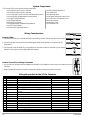
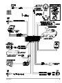
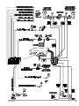
1
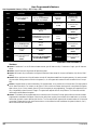
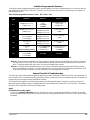
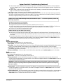
Standard Features of the Concept 600
The Clifford Concept 600 system is designed to be installed in any vehicle with a 12-volt battery.
¨ Thatcham-Evaluated
¨ Complete System Diagnostics At-A-Glance
¨ Lifetime Warranty
¨ Self-Powered SmartSiren 4
¨ Up to £500 AntiTheft Guarantee
¨ Automatic Low Siren Battery Warning
¨ His & Hers Remote Controls
¨ FACT — False Alarm Control and Test
¨ ACG™ 2 (Anti-CodeGrabbing™)
¨ Remote Panic with Smart Locking/Unlocking
¨ Superheterodyne Extended Range Receiver
¨ Integrated Electronic Timer
¨ Audible Low-Battery Warning
¨ Remote Headlight Activation Capability
¨ Digital Tilt/Motion Sensor
¨ Remote Door Locking/Unlocking with Built-in Relays
¨ Completely Automatic Self-Adjusting
¨ User-Selectable AutoLock
¨ Built-In Two-Point AutoImmobiliser™
¨ User-Selectable AutoUnLock
¨ Wireless FuelGuard™
¨ Built-In Dual Indicator Light Flasher with Onboard Relay
¨ Electronically Programmable Proximity Sensor
¨ Remote-Controlled Courtesy Lighting
¨ Patented UltraSecure Coded Valet Mode™
¨ Smart Remote Boot Release
¨ Built-In Window RollUp
¨ Patented Smart AutoTesting™
¨ Easy Window RollUp Bypass
¨ Patented Malfunction AutoBypass™ with
AutoReMonitoring
¨ Enhanced User-Selectable AutoArming
¨ AutoArming Enable/Disable
¨ AutoArm & Lock
¨ Visual Indication
¨ Instant AutoArm Bypass
¨ User-Selectable Remote Valet Mode Entry/Exit
¨ Remote Keyless Entry and Accessory Activation Even in
Valet Mode
¨ Eight-Event TotalRecall™
¨ Built-In BlackJax Anti-Carjacking System
¨ True Carjack Protection
¨ Safe & Intelligent Engine Shutdown
¨ Immediate Vehicle Recovery
¨ Ensuring Immobilisation
¨ Sabotage-Proof Operation
¨ Patented Smart Prior Intrusion Attempt Alert
¨ Patented Remote Control Code Learning and
MultiRemote Recognition
¨ Clear All Remotes
¨ Multiple-Car Control
¨ High-Luminescence LED Status Indicator with Automatic
Battery-Saving Mode
¨ Multiple Sensor/Trigger Inputs
¨ Patented SmartPowerUp™ 2
¨ Full-Time SecureAccess™ Programming
¨ Dual Ground Lines
¨ Advanced CMOS Microcomputer
¨ Pre-Loomed Wiring
¨ Three Accessory Outputs with Selectable Output Types
¨ AutoActivation of Accessory Output B
¨ Optional DataPort™ Interface and CliffNet Wizard Pro™
Software
¨ Installer-Selectable Door Ajar/Delayed Courtesy Lights
¨ Point-and-Click Feature Programming
¨ Prewired LED, Sensor, Siren, Extended Range Receiver,
and PlainView 2 Switch Connectors
Concept 600/299
1
System Components
The Concept 600 kit contains the following components:
One Prewired 24-pin Connector Harness
One Prewired 14-pin Connector Harness
One Concept 600 Control Unit with Stainless Steel Enclosure
One Electronically Programmable Proximity Sensor
One Digital Tilt/Motion Sensor
One Wireless FuelGuard
Two Remote Transmitters
One Superheterodyne Extended Range Receiver
One LED Status Indicator
One PlainView Coded Valet Switch 2
One Self-Powered SmartSiren 4
One Hardware Kit
One Owner’s Manual
One Wireless FuelGuard Location Form
One Certification of Installation Form
Two Window Decals
One Warranty Card
One Guarantee Card
Wiring Considerations
How to Solder
1. Strip about one-half-inch of insulation from the wires and slip a piece of shrink tubing over one of them.
2. Join the wires, then heat the wires with a soldering gun whilst touching solder to the wires until the
solder melts.
3. Pull the wires to test the solder joint, then position the loose shrink tube over the solder joint and gently
heat with a hot air gun so that it tightly seals and insulates.
How to Secure Non-locking Connectors
1. Join the two non-locking connectors together as indicated in the installation instructions for the component you are
installing.
2. Wrap the cable tie around the connector as shown and tighten it securely around the connectors.
Wiring Description for the 24-Pin Connector
Pin Colour
Connects to
1
3
4
5
6
8
9
Red/Black
White/Blue
Violet
Black/Grey
Red
Grey/Yellow
Black
10
11
13
14
15
17
18
20
23
24
Black
White
Grey/Violet
Grey/Blue
Grey/Red
Yellow
Red
Green
White/Black
Orange
Prewired to the Proximity Sensor output
Prewired Proximity Sensor input connector
Prewired to the LED connector
Ignition coil or tach input
Prewired to the Tilt Sensor and siren connectors
Boot trigger switch
Prewired for the siren, sensors, LED and valet
switch
Ground
Prewired to the Valet Switch connector
Auxilliary A output
Auxilliary B output
Auxilliary C output
Optional airhorns
Battery
Prewired to the Tilt Sensor connector
Bonnet trigger switch
Prewired to the Tilt Sensor connector
2
Inputs
Outputs
5V Max.
Analog
Positive, 16mA Max.
Pulse
Positive, 3.5V Min.
Negative, 3.5V Min.
Ground
Ground
Negative-3.5V Min.
Negative, 250mA Max.
Negative, 250mA Max.
Negative, 250mA Max.
Negative, 250mA Max.
Positive, 7V Min., 18V Max.
Negative, 250mA Max.
Negative, 3.5V Min.
Negative, 3.5V Min.
Concept 600/299
Concept 600/299
3
Wiring Description for the 14-Pin Connector
Pin Colour
Connects to
1
2
3
6
7
8
9
10
Brown
Blue/White
Brown
White/Orange
White/Green
Red/White
Brown/Red
Grey
Indicator light output
Brake output
Indicator light output
Door unlock common
Door lock common
Indicator and brake light input
Interior light input (+ or -)
Door trigger input (+ or -)
Inputs
11
12
13
14
Red/Orange
Red/Green
Grey/Green
Grey/Orange
Door unlock normally open
Door lock normally open
Door lock normally closed
Door unlock normally closed
Positive, Vbatt
Vbatt or Ground
Negative, 3.5V;
Positive, 4V
Outputs
Max. 15A
Max. 15A
Max. 15A
Max. 15A
Max. 15A
Max. 15A
Max. 15A
Max. 15A
Max. 15A
Max. 15A
Wiring Description for the 12-Pin Connector
Pin Label
Connects to
Inputs
1
2
3
4
5
6
8
9
10
11
Ground
Window switch 2
Window motor 1
Window switch 1
Fuse panel (+)
Starter input
Ignition output
Window motor 2
Starter output
Ignition input
Min. 12 mA; Max. 5A
Relay, Max. 20A
Ground
Window switch 2
Window motor 1 +12V out
Window switch 1
Constant +12V 30A
Starter input +12V
Ignition output +12V
Window motor 2 +12V out
Starter output +12V
Ignition input +12V
Outputs
Max. 30A
Relay, Max. 20A
Positive, Vbatt
Relay, Max. 30A
Continuous 20A, Max Surge 30A
Max. 30A
Continuous 20A, Max Surge 30A
Relay, Max. 30A
The current draw of the entire vehicle security system (whilst armed) is 20mA. Power supply voltage is 7V
minimum and 18V maximum.
Passenger Compartment Connections
Control Unit and Superheterodyne Extended Range Receiver
The Concept 600 control unit must be installed inside the vehicle. Under no circumstances should the unit be
installed under the bonnet or other similarly hostile environment.
1. Select an area behind the dash to mount the control unit using the supplied wire tires, but do not permanently affix it until all
wiring and testing is complete. To maximize the sensitivity of the tilt/motion sensor, make sure the control unit is mounted as flat
as possible behind the dash (i.e., not mounted on its side).
2. Plug the extended range receiver in to the control unit. Mount the extended range receiver away from the control unit and run
the antenna either up the window pillar and affix it to the windscreen, or under the dash, away from metal. The position and
location of the receiver will effect remote control range. Do not fold the excess cable or antenna wire. Do not make hard, sharp
bends.
Door Trigger/Interior Light Supply
Please refer to the Door Trigger/Interior Light Supply section in this binder for information on polarity testing and connections.
Central Door Locking System
Please refer to the Door Locks section in this binder for information on circuit types and connections.
4
Concept 600/299
Concept 600/299
5
Passenger Compartment Connections (Continued)
LED Status Indicator
Select a prominent location on the dash or console visible through all windows. Discuss placement with the owner.
1. Verify there is adequate space to accommodate the LED, then drill a 5/16” (8mm) hole and route the wires through it.
2. Mate the LED connectors to the VIOLET and BLACK wire connectors as shown in the diagram on page 5.
3. Remove the adhesive backing and press the switch into place.
PlainView Coded Valet Switch 2
1.
2.
3.
4.
5.
Discuss placement of the switch with the vehicle owner and avoid placing the switch where it can be pressed accidentally.
Verify there is adequate space behind the selected location to accommodate the switch.
Drill a 5/16” (8mm) mounting hole, then insert the wires through the hole.
Mate the switch’s locking connectors to the WHITE and BLACK locking connector.
Remove the adhesive backing and press the switch into place.
Remotely Adjustable Dual-Zone Proximity Sensor
This efficient new-generation proprietary radar sensor is immune to the wind and temperature variations that cause ultrasonic
sensors to false alarm. The sensor must be mounted onto a metal surface and face outward into the passenger compartment. It should
be positioned as close as possible to the centre of the passenger compartment. Suggested mounting locations include within the
centre console, behind the dash, under the carpeting of the central hump or even in the headlining. When selecting a location, keep
in mind that metal as well as metallic paint, metallic-coloured plastic and metal-laced window tint material will interfere with the
radar field. Be certain not to mount the sensor under a location where the vehicle owner may store coins, CDs or cassettes
(iron-oxide tape). The radar waves of the sensor will pass through nonmetallic materials such as plastic, fabric and carpet.
1. Temporarily affix the sensor where it will be mounted, but do not yet permanently mount it until after adjusting and testing
sensitivity (the sensor may need to be relocated, so do not permanently secure it until it has been thoroughly tested).
2. Join the Proximity Sensor to the connector with the BLACK, WHITE/BLUE and RED/BLACK wires, then secure the wires with a
cable tie.
Optional Dual-Zone OmniSensor
1. Firmly mount the OmniSensor module on a flat surface on the center of the firewall (passenger or engine compartment side). The
arrow on the module must point straight up.
2. Plug the connector in to the connector on the wireloom (route through a grommet if mounted on the engine compartment
firewall).
3. Adjust sensitivity using the instructions provided later in this manual under the Sensor Adjustment section.
Digital Tilt/Motion Sensor
Find a solid, firm horizontal surface within the passenger compartment (such as under the seat or structural support under the dash)
and thoroughly prep the area for mounting. Do not mount the sensor on the transmission hump, very rapid heat buildup can affect
sensitivity. The unit is mounted with the supplied double-sided adhesive material, so the mounting area must be very clean.
1. Mount the unit onto a clean, horizontal surface using the supplied double-sided adhesive material.
2. Join the connector from the Digital Tilt/Motion Sensor with the connector with the GREEN, ORANGE, RED and BLACK wires,
then secure the wires with a cable tie.
NOTE: The Digital Tilt/Motion Sensor will become active 10 seconds after arming the Concept 600. Suspension
systems on some vehicles, such as Range Rovers and Citroens, lower after the ignition is turned OFF and will
require more time before the sensor becomes active. To extend this time delay, cut the black sensor wireloop
— this will provide a two-minute delay.
Boot Trigger
Vehicles with an ground-switching boot light will interface directly with the Concept 600 (on positive switching Rolls-Royce vehicles, use a
relay to invert polarity). The switch may be located in or near the boot latch or at the boot light. If a switch cannot be located, you
must add a pin switch in a location away from water channels.
NOTE: If the vehicle has a dashboard boot ajar indicator, install a 1-amp diode between the light and switch
with the diode band pointing toward the switch.
1. Connect the GREY/YELLOW wire to the boot switch (between the diode and switch if you added a diode).
6
Concept 600/299
Passenger Compartment Connections (Continued)
Brake Switch
The brake switch connection is required for the operation of the Concept 600’s anti-carjacking electronics.
1. Turn the ignition to the “ON” position and press the brake pedal to verify that the brake lights are operational.
2. Find the one wire that carries +12V when the brake pedal is pressed, then connect the BLUE/WHITE wire to this wire.
Indicator Lights
See the Indicator Lights section in this binder.
Starter and Ignition AutoImmobilisation Circuits
1. Locate the ignition switch wireloom under the dash and use a voltmeter to locate the one wire that carries +12V throughout
BOTH the cranking AND engine running cycles, and 0 volts when the ignition is off.
2. Start the engine, then cut the ignition wire. The engine should stop running.
3. As shown on page 3, connect the BLACK wire with the Ignition Input +12 Volts label to the key side of the cut ignition line.
4. Connect the BLACK wire with the Ignition Output +12 Volts label to the engine side of the cut ignition line.
5. Use a voltmeter to locate the one wire that carries +12V during the cranking cycle ONLY. Cut this wire, then try to start the
engine. It should not crank.
6. Connect the BLACK wire with the Starter Input +12 Volts label to the key side of the cut starter line.
7. Connect the BLACK wire with the Starter Output +12 Volts label to the engine side of the cut starter line.
NOTE: The starter circuit may carry a very high current. Be certain that the starter wire connections are solid.
8. Remove the labels from each of the four wires.
Auxilliary A with Selectable Output Type
The auxilliary A output (GREY/VIOLET wire) can be programmed as either pulsed, latched or timed and can be programmed to
operate only when the system is disarmed (e.g., for use as a remote boot release). Auxilliary A output is activated by transmitting
channel 2 from the master remote control or by pressing the
button on the companion remote. The factory setting is pulsed
output (0.5 second ground). The latched output stays at ground until channel 2 is activated a second time, and the timed output
stays at ground for any selected duration between one second and four minutes. Current is limited to 0.15 amp. See
Installer-Programmable Features on page 15 for information on programming the output type and/or disabling operation whilst the
system is disarmed.
Auxilliary B with Selectable Output Type
The auxilliary B output (GREY/BLUE wire) can be programmed as either pulsed, latched, or timed. The auxilliary B output is activated
by transmitting channel 7 from the master remote or by pressing the
button on the companion remote. Current is limited to 0.15 amp.
The latched output stays at ground until channel 8 is activated a second time, and the timed output stays at ground for any selected
duration between one second and four minutes. See Installer-Programmable Featureson page 15 for more information on programming
output type.
Auxilliary C with Selectable Output Type and AutoActivation
The auxilliary C output (GREY/RED wire) can be programmed as either pulsed, latched or timed and in addition, can also be
programmed to automatically activate every time the system is armed using the remote control. The auxiliary C output is activated
by transmitting channel 8 from the master remote control or by pressing the
and
buttons on the companion remote. The
factory setting is pulsed output (0.5 second ground). AutoActivation is perfect when programmed as a timed-output to close the
power windows and sunroof on vehicles that have an all-close feature. The latched output stays at ground until channel 8 is
activated a second time, and the timed output stays at ground for any selected duration between one second and four minutes.
Current is limited to 0.15 amp. See Installer-Programmable Features on page 15 for information on programming the output type
and/or enabling the AutoActivation feature.
Window RollUp
Please refer to the Window Control section in this binder for information on the various circuit types and connections.
Concept 600/299
7
Engine Bay Connections
RPM Monitoring
This is required for both RPM-activated automatic door locking and for BlackJax anti-carjacking
features. See the RPM Monitoring section in this binder for information.
Self-Powered SmartSiren 4
The control unit and siren utilise two-way digital signal transmissions to maintain a constant
communication link. If the communication link is broken whilst the system is armed (if a thief
disconnects power or tampers with the siren wires), the siren will sound for five minutes and then
reset. Since this will only occur whilst the system is armed, there is no need for a siren override key.
Unlike other back-up battery sirens that constantly drain the car battery, Clifford’s design draws
charging current only when the ignition is on (i.e., engine running). If the internal battery is flat,
the arm/disarm chirps are muted.
1. You must firmly secure the siren to the engine bay firewall or an inner wing using all three sheet metal screws supplied. Mount the
siren away from areas of water ingress or excessive heat. Point the siren down to avoid moisture.
2. Run the cable from the Self-Powered SmartSiren through the firewall into the passenger compartment using caution as not to tear
the pins from the end of the cable.
3. Push the pins connected to the GREEN, YELLOW, BLACK and RED wires into the supplied connector as illustrated on page 3.
a. The pin with the GREEN wire connects to the slot labeled “4.”
b. The pin with the YELLOW wire connects to the slot labeled “3.”
c. The pin with the BLACK wire connects to the slot labeled “2.”
d. The pin with the RED wire connects to the slot labeled “1.”
4. Join the connector from the siren to the connector with the GREEN, YELLOW, BLACK and RED wires from the wireloom and
secure the connectors with a cable tie.
5. Insert the DataPort connector with the YELLOW and GREEN wires into the DataPort on the control unit.
NOTE: The vehicle must be driven for a total of eight hours after the siren has been installed in order to
sufficiently charge the siren’s back-up battery.
Bonnet Trigger
Vehicles with an ground-switching bonnet pin switch interface directly with Concept 600 (on positive switching Rolls-Royce vehicles, use a
relay to invert polarity). If a switch cannot be located, you must add a pin switch in a location away from water channels.
1. Connect the WHITE/BLACK wire to the bonnet pin wire (between the diode and pin switch if a diode was added).
NOTE: If the vehicle has a dashboard bonnet ajar indicator, install a 1-amp diode between the light and
switch with the diode band pointing toward the switch.
Final Wiring Connections
1.
2.
3.
4.
5.
Connect the RED wire to the 5-amp fuseholder as shown on page 3.
Connect the BLACK wire labeled +12 Volt 30 A to the 30-amp fuseholder as shown on page 5.
Connect the RED/WHITE wire to the 20-amp fuseholder as shown on page 5.
Attach the three fuseholders to the constant +12V source at the fuse panel.
Use ring connectors to attach the two different BLACK wireloom wires, each labeled Ground, to two different chassis ground
points or one of them directly to the vehicle fuse panel ground. The ground points must be very clean. A factory bolt that has
been completely cleaned with a wire brush is recommended.
NOTE: Power and test accessories after the basic system has been tested. Individually fuse all accessory power
connections. Individually fuse all +12V fuse panel connections.
SmartPowerUp™ 2
SmartPowerUp 2 ensures that the system powers up in the same state (disarmed, armed or valet mode) it was in when power was removed.
When you first power up the Concept 600, it will silently enter the disarmed state.
Wireless FuelGuard
Do not install the Wireless Fuelguard until all other components of the security system installation have been completed and the
system has been powered up! Please refer to the Wireless FuelGuard section of this binder for installation instructions.
8
Concept 600/299
Delayed Courtesy Lights
Some vehicles have a courtesy light delay or dimming circuit, which interferes with an alarm being able to detect the door trigger upon
remote arming. If the delay or dimming lasts more than 5 seconds, no special connections or testing are needed, simply turn on the Delayed
Courtesy Lights feature as noted in the Installer-Programmable Features section on page 15. Please note that since this feature sets the
system to arm the instant the courtesy lights turn off, the Door Ajar Warning feature will not be available.
Mandatory RPM Programming
NOTE: This MANDATORY programming step must be completed for the Concept 600 to operate properly.
1. Drive the vehicle to a nearby open area and allow the engine to warm-up until the RPMs drop to the normal idle speed.
2. With the engine still running, place the transmission in Park (or Neutral if the vehicle has a manual transmission).
3. Enter the customer’s valet code using the instructions provided in the Programmable Features on page 13. The assigned valet code
is noted on the inside front cover of the owner’s manual. The LED will briefly illuminate. Press and hold the ✱ button for 10
seconds (you will hear one confirmation chirp after three seconds—do not stop holding the button—continue holding the button
until you hear a three-chirp confirmation). Release the button.
4. Press the unmarked button once. After a three-second pause, the system will sound one chirp to confirm column one selection
(see the Installer-Programmable Features section on page 15).
5. Press the ✱ button five times (you will hear a chirp each time you press the button) to select row five. After a two-second pause,
you will hear two chirps to confirm idle RPM has been set (if you hear just one chirp, check the connection of the BLACK/GREY
wire, then repeats steps 1 - 5).
6. Turn the ignition OFF.
Remote Control Operation
The Concept 600 comes with two ergonomically designed remote controls: a 5-button master remote and a 4-button secondary
“companion” remote. Up to four additional Concept series remote controls can be added to the Concept 600 system. Due to the
ACG 2 feature on the Concept series systems, older Clifford ACG and non-ACG remotes are not compatible with the Concept 600.
Master Remote Control Operation
To transmit either channel 1, 2, 3 or 4: Just press either button 1, 2, 3 or 4. For instance,
to transmit channel 3, press button 3. Whilst you transmit, the LED indicator on the
remote control will flash once every second: this indicates level 1.
To transmit either channel 5, 6, 7 or 8: Press the LevelShift button once. This shifts
buttons 1–4 to level 2 (channels 5–8). Then press the desired button within the next 7
seconds. For instance, to transmit channel 5, press the LevelShift button once, then press
button 1. Whilst you transmit, you’ll notice that the LED indicator on the remote control
flashes twice, pauses, flashes twice, etc.: this indicates level 2.
To transmit channel 9, 10, 11 or 12: Press the LevelShift button twice. This shifts the
buttons to level 3 (channels 9–12). Then press the corresponding button within the next 7
seconds. For instance, to transmit channel 10, press the LevelShift button twice, then press button 2. Whilst you transmit, you’ll notice
that the LED on the remote control flashes three times, pauses, flashes three times, etc.: this indicates level 3.
To transmit channel 13, 14, 15 or 16: Press the LevelShift button three times. This shifts the buttons to level 4 (channels 13–16).
Then press the corresponding button within the next 7 seconds. For instance, to transmit channel 14 press the LevelShift button three
times, then press button 2. Whilst you transmit, you’ll notice that the LED on the remote control flashes four times, pauses, flashes
four times, etc.: this indicates level 4.
NOTE: One second after you stop transmitting levels 2, 3 or 4 (channels 5–16), the remote control
automatically returns to level 1 (channels 1–4).
Concept 600/299
9
Master Remote Control Channel Assignments
Function
Press
Button
Function
1
Arm/Disarm
9
Remote Valet
2*
Activate Auxilliary A Output
(usually remote boot release)*
10
Proximity Sensor Override
3
Silent Arm/Disarm
11*
Unassigned or IntelliStart 4 Features (Low Temp/Low
Battery AutoStart or Manual Transmission SafeStart)*
4*
IntelliStart 4 Accessory*
(IntelliStart 4 not evaluated by Thatcham)
12*
Unassigned*
5*
Unassigned*
13*
Unassigned*
6*
SmartWindows 4 Accessory*
14*
Unassigned*
7*
Activate Auxilliary B Output*
(such as timed headlight activation)
15
Adjust Sensitivity of Optional OmniSensor
8*
Activate Auxiliary C Output
(Usually IntelliVoice accessory)*
16
Adjust Sensitivity of Proximity Sensor
Press
Button
* These channels can be assigned to control other Clifford ACG 2 systems and accessories on multiple vehicles.
Function
Press button(s)
Arm/Disarm
Activate Auxiliary A Accessory*
(usually remote boot release)*
+✱
Silent Arm/Disarm
Activate Auxiliary B Accessory*
(such as timed headlight activation)
✱
IntelliStart 4 Accessory*
(IntelliStart 4 not evaluated by Thatcham)
+
+✱
+
SmartWindows 4 Accessory*
Remote Valet Mode Enter/Exit*
Activate Auxiliary C Output
(Usually IntelliVoice accessory)*
+✱
Unassigned*
Remote Proximity Sensor Override
+
* These channels can be assigned to control other Concept systems and accessories on multiple vehicles.
Sensor Adjustment
Digital/Tilt Motion Sensor
The Digital Tilt Motion Sensor is completely self-adjusting. No senstivity settings or adjustments are ever required.
Electronically Programmable Proximity Sensor
The Concept 600 is equipped with our unique Electronically Programmable Proximity Sensor that uses digital signal processing to
detect movement inside the passenger compartment and very near the vehicle. If a thief were to break a window and either enter or
lean into the passenger compartment, the primary zone of this sensor would trigger the full alarm. However, if a thief brought his
hands and face to the window a warning tone would sound.
Be aware that the Proximity Sensor uses radar waves to detect movement. These waves pass through nonmetallic materials like
plastic, carpet, glass and wood. However, metal and metallic-colored paint, metallic-colored plastic and even some metallic window
tinting materials will interfere with or completely block the radar waves. As such, it is not unusual that the Proximity Sensor zones
require some adjustment after installation. In some instances, you may need to try a different location for the sensor.
10
Concept 600/299
Sensor Adjustment (Continued)
Electronically Programmable Proximity Sensor (Continued)
Since any metal objects above or near the Proximity Sensor will have a significant impact on operation, warn
your customer never to place coins, CDs, cassettes (due to the iron oxide tape) or other metallic objects above
or near where the sensor is mounted.
1.
2.
3.
4.
Turn off any fluorescent lights that may interfere with the sensitivity testing of the Concept 600’s radar sensor.
Disarm the system with the remote control.
Transmit channel 16 on the master remote (LevelShift three times, then button 4). You will hear one chirp and the LED will turn on.
Test the Proximity Sensor’s primary zone by rapidly leaning through an open window into the passenger compartment. You will
hear a siren chirp when the primary zone is triggered. This should not occur near the window, but instead when you would be in a
position to touch the car stereo.
To change the sensitivity of the primary zone, press and release button 2 to increase sensitivity or button 4 to decrease sensitivity.
To rapidly increase or decrease several steps, press and hold the button. For each sensitivity increase, you will hear a higher and
higher pitched confirmation chirp. For each sensitivity decrease, you will hear a lower and lower pitched confirmation chirp. Two
LoudChirps indicate minimum and maximum settings of the 32-step range of settings. You may now press button 3 to adjust the
warning zone, or press button 1 to fully exit the Proximity Sensor adjustment mode (you will hear 3 chirps).
To change the sensitivity of the warning zone, press button 3 (you’ll hear 1 chirp). Then use the same procedure as above, but this
time, rapidly bring your hands and face to the window as a thief would to see what’s inside. The sensitivity of the warning zone
should be set so that it is triggered when your face and hands are within a few inches of the window, no further. When done, press
button 1 to reselect the primary zone (you will hear 2 chirps), then button 1 again to fully exit Proximity Sensor adjustment mode
(you will hear 3 chirps).
5. Repeat the preceding steps as required. An improperly adjusted sensor will cause the Concept 600 to false alarm or not respond
properly to a genuine threat. Keep in mind that you may need to reposition the sensor, possibly after the customer has had the
system for several days.
Remote-Controlled Override of Each Proximity Sensor Zone
Transmitting channel 10 at anytime from the remote whilst the system is armed will override the warning zone of the Proximity
Sensor. This prevents the system from sounding warnings if the vehicle must be parked in an area with heavy pedestrian traffic. A
second transmission of channel 10 anytime afterward whilst the system is still armed will override both zones of the Proximity Sensor.
This comes in handy when a pet or a passenger must be left in the vehicle. The channel 10 warning zone override is visually
confirmed with 4 flashes of the indicator lights. A second channel 10 transmission to override both zones is confirmed with four more
flashes. The sensor zones are automatically restored the next time you arm.
Optional Dual-Zone OmniSensor Adjustment
Our optional Dual-Zone OmniSensor uses digital signal processing to detect vibration and/or impact to the vehicle. If a thief were to
break a window or cause any impact to the vehicle, the primary zone of this sensor would trigger the full alarm. However, if a thief
brushed against the vehicle a warning tone would sound.
1. Disarm the system with the remote control.
2. Transmit channel 15 on the master remote (LevelShift three times, then button 3). You will hear one chirp and the LED will turn on.
n To adjust sensitivity of the primary zone:
q To change the sensitivity of the primary zone, press and release button 2. You will hear 1 chirp.
q To make a new sensitivity setting, press button 2. You will hear 2 chirps.
q Thump the car firmly with your fist, you will hear one chirp.
q Press button 4, you will hear two chirps.
q You may now test sensitivity by thumping the vehicle firmly with your fist. You should hear one chirp.
q At this point, you can:
Press button 2 to make another new setting for the primary zone (you will hear two chirps).
Press button 1 to exit (you will hear three chirps).
Press button 3 to adjust the warning zone (see instructions on the next page).
Concept 600/299
11
Sensor Adjustment (Continued)
Dual-Zone OmniSensor Adjustment (Continued)
n To adjust sensitivy of the warning zone:
q To change the sensitivity of the warning zone, press button 3 (you’ll hear 1 chirp).
q To make a new sensitivity setting, press button 2. You will hear 2 chirps.
q Thump the car lightly with your fist, you will hear one chirp.
q Press button 4, you will hear two chirps.
q You may now test sensitivity by thumping lightly with your fist. You should hear one chirp.
q At this point, you can:
Press button 2 to make another new setting for the warning zone (you will hear two chirps).
Press button 1 to adjust the primary zone (see instructions above)(you will hear two chirps).
Press button 1 two times to exit sensitivity adjustment mode.
4. Repeat the preceding steps as required. An improperly adjusted sensor will cause the Concept 600 to false alarm or not respond
properly to a genuine threat. Keep in mind that you may need to readjust the sensor, possibly after the customer has had the
system for several days.
FACT—False Alarm Control and Test
The system microprocessor automatically checks for another activated sensor or trigger before sounding the siren a second time, thus
preventing any further false alarms. If you wish to test FACT, simply:
1.
2.
3.
4.
5.
Arm the Concept 600 with the remote control.
Wait 10 seconds after the interior light turns off, then trigger the Proximity Sensor to activate the siren.
Do not disarm the system, let the siren complete its cycle.
Trigger the sensor again. The alarm should be silent.
Unlock and open a door. The alarm should sound immediately. You may now disarm.
Eight-Event TotalRecall
The system’s nonvolatile memory records the identity of the last eight activated or malfunctioning triggers and sensors:
NOTE: The CliffNet Wizard Pro displays the Eight-Event TotalRecall data in a graphical format .
1.
2.
3.
4.
With the ignition OFF, press and hold the unmarked side of the PlainView 2 Switch.
Press remote control button 1 to “arm,” and then again to “disarm,” and then release the button.
The LED will flash 1–10 times, pause, then flash 1–10 times, etc. Write down the number of flashes in each cycle.
Refer to the following chart. The first number you wrote down was the most recently activated trigger or sensor. The next number
is the second most recent, and so on up to as many as the last eight activations.
LED flashes
Trigger/sensor indication
1 flash
Electronically Programmable Proximity Sensor
2 flashes
Optional OmniSensor
3 flashes
Digital Tilt/Motion Sensor
4 flashes
Door Trigger
5 flashes
Boot Trigger
6 flashes
Bonnet Trigger
7 flashes
An attempt was made to turn on the ignition or start the engine whilst the system was armed
8 flashes
More than three consecutive incorrect valet codes were entered whilst the system was in BlackJax mode
9 flashes
BlackJax Activation
10 flashes
System Power Interruption
5. If a sensor is often activated, decrease that sensor’s sensitivity (or reposition the sensor, if necessary). If a certain trigger is often
activated, check pin switch operation, verify that the pin switch is not exposed to moisture and check the trigger wire for possible
shorting.
12
Concept 600/299
Certificate of Installation/Ownership/Operation
After installation and testing has been completed, you must fill in the Clifford Electronics “Certificate of Installation/
Ownership/Operation.” Once you have filled in all the information required on the form, be sure that the customer signs and dates
the certificate. See step 18 in the System Checklist & Troubleshooting section for instructions on distributing the form.
Programmable Features
Concept 600 comes from the factory with its features preprogrammed as noted in bold text in the tables on pages 14 and 15. Some
features can be programmed by the installer or the user, others can only be programmed by the installer. There are two tables
provided which define the user-programmable and installer-programmable features.
Using the CliffNet Wizard Pro
The CliffNet Wizard Pro provides almost intuitive access to all installer and user-programmable features through a user-friendly,
graphical user interface. Because CliffNet Wizard Pro is Windows™-compatible, most operations can be accomplished by simply
pointing and clicking a mouse. CliffNet Wizard Pro totally eliminates complicated programming charts and lengthy programming
sequences. Please refer to the CliffNet Wizard Pro User’s Guide for more programming information if you are using the CliffNet
Wizard Pro. Otherwise, for manual programming refer to the tables provided in the following sections.
Programming the User-Selectable Features
1. Write down the column (across) number and row (down) number of the feature(s) you wish to program.
2. Turn the ignition to the “ON” position or start the engine.
3. Enter the factory preset valet/programming code noted on the inside front cover of the owner’s manual by pressing the PlainView
2 Switch’s ✱ button the number of times of the first digit, then press the unmarked button (then repeat for each subsequent digit.
For example, if the code is 1302, you would press the following: ✱ unmarked, ✱ ✱ ✱ unmarked, unmarked, ✱ ✱ unmarked.)
4. After entering the code, press and hold the ✱ for about 3 seconds until you hear one siren chirp and the LED turns on to
acknowledge program mode entry. The Concept 600 is now in the “Feature Select” position for User-Programmable Features.
5. Select the feature column: Press the unmarked button the same number of times as the column number. Pause. You will then hear
the same number of chirps as the column number you have selected, audibly confirming your selection.
6. Within five seconds, select the feature row: Press and release the ✱ button the same number of times as the feature’s row number.
You’ll hear a chirp each time you press the unmarked side to help you count.
7. If there is a NOTE for the selected feature, perform the actions noted.
8. Pause. You will hear either one or two chirps: two chirps = ON, one chirp = OFF.
9. You can select another feature, or you can exit program mode:
a. To select another feature in that same column, repeat step 6 within the next five seconds (after five seconds, three chirps
indicate that the Concept 600 is now back in the “Feature Select” position).
b. To select a different feature column, repeat step 5.
c. To exit program mode, turn the ignition off (you’ll hear three chirps and the LED will turn off to indicate exit of program
mode), or wait 60 seconds and the Concept 600 will automatically exit program mode.
It may sound a little complicated, but it really isn’t. Briefly, here is all you do: choose the feature you want to change, enter program
mode, select that feature’s column and row, wait for the on/off chirp confirmation, then turn off the ignition. That’s it!
Concept 600/299
13
User-Programmable Features
User-Programmable Features (1 Chirp = OFF, 2 Chirps = ON)
Feature
Select
Unmarked 1
Unmarked 2
Unmarked 3
Unmarked 4
✱1
AutoProgram New Master
Remote NOTE 1
Chirps
(Off/LoudChirps/QuietChirps)
(1 chirp/2 chirps/3 chirps)
AutoArming
(On/Off)
Arm/Disarm with
Secondary Remote
NOTE 5
✱2
NOT USED
NOT USED
AutoArm & Lock
(On/Off)
Boot Release with
Secondary Remote
NOTE 6
✱3
NOT USED
Remote Valet Feature
(On/Off)
NOT USED
Silent Arm/Disarm with
Secondary Remote
NOTE 6
✱4
NOT USED
AutoStart using optional IntelliStart 4*
(Both/Neither/Battery/Temperature)
(1 chirp/2 chirps/3 chirps/4 chirps)
NOTE 3
FACT
(Off/On)
Remote Start with
Secondary Remote
NOTE 6
✱5
AutoLock
(Off/Instant/RPM-Dependent)
(1 chirp/2 chirps/3 chirps)
BlackJax
(Off/On)
NOT USED
Timed Headlights with
Secondary Remote
NOTE 6
✱6
AutoUnlock
(Off/On)
Clear All Remotes
NOTE 4
NOT USED
Window Rolldown/Venting
with Secondary Remote
NOTE 6
✱7
Reset All to Factory Settings
(except remote controls and
valet code)
NOTE 2
Valet Code
SHOULD ONLY BE PROGRAMMED
BY THE VEHICLE OWNER
NOT USED
Remote Valet Mode
with Secondary Remote
NOTE 6
Thatcham
*IntelliStart 4 not evaluated by
n NOTE 1: Press button 1 on the 16-channel master remote, you will hear one chirp. Press button 1 again, you will hear two
chirps.
n NOTE 2: You will hear two chirps when all features are reset.
n NOTE 3: With each chirp confirmation the lights will flash two times, except for the one confirmation chirp for the “Both”
setting.
n NOTE 4: When you hear two chirps, all remote controls will have been erased from the system memory. You must now add
the new and/or existing remote controls to the system (i.e., AutoProgram each remote that will be used with the Concept
600).
n NOTE 5: Programs either a 4-channel secondary, 16-channel master, or any remote control from another Concept system to
arm or disarm the vehicle. For instance, to set button 13 of the other car’s master remote control to arm/disarm the system,
select column 4, row 1, then transmit channel 13 from the remote you are programming. The system will respond with one
chirp. Immediately transmit channel 13 again. The system will respond with two chirps. Button 13 of the other vehicle’s
remote will now arm/disarm the system.
n NOTE 6: This feature can be programmed onto the remote control of another Concept system, after that remote has been
programmed to arm/disarm this system. Select the row and column number, then transmit the unused button on the other
remote that you want to use to perform that function. The Concept 600 will respond with the same number of chirps as the
row number. Please note that you must first set a button on the remote that will arm/disarm the system (column 4, row 1)
before these others will be accepted.
14
Concept 600/299
Installer-Programmable Features
To access the installer-programmable features, use the procedure defined in the User-Programmable section, but in step 4, hold and
press the ✱ side of the PlainView 2 Switch for 10 seconds. You will hear three confirmation chirps indicating that the system is in
installer-program mode.
Table of Installer-Programmable Features (1 chirp = OFF, 2 chirps = ON)
Feature
Select
Unmarked 1
Unmarked 2
Unmarked 3
✱1
Single/Double Lock Pulse
(1 chirp/2 chirps)
Accessory Output Timer
Duration
(10 seconds)
See NOTE 1
Door Ajar Warning/Delayed
Courtesy Lights
(1 chirp/2 chirps)
✱2
Single/Double Unlock Pulse
(1 chirp/2 chirps)
Auxiliary A Type
(Pulsed/Timed/Latched)
(1 chirp/2 chirps/3 chirps)
Auxiliary A Interlock
(On/Off)
✱3
Lock/Unlock Pulse
3 second/1 second
(1 chirp/2 chirps)
Auxiliary B Type
(Pulsed/Timed/Latched)
(1 chirp/2 chirps/3 chirps)
Auxiliary B Interlock
(On/Off)
✱4
AutoActivate Auxiliary B upon
Remote Arming
(On/Off)
Auxiliary C Type
(Pulsed/Timed/Latched)
(1 chirp/2 chirps/3 chirps)
Auxiliary C Interlock
(On/Off)
✱5
Program RPM
See
Mandatory RPM Programming
Diesel Engine/Petrol Engine
(1 chirp/2 chirps)
(For IntelliStart 4 only*)
Program Window RollUp or
SmartWindows 4
See NOTE 2
✱6
Auxiliary Siren Output
(Constant/Pulsed)
(1 chirp/2 chirps)
NOT USED
NOT USED
*IntelliStart 4 not evaluated by Thatcham
n NOTE 1: Once this feature is selected, one chirp is provided to indicate that the timer has started. You can set this anywhere
from one second to four minutes. When the desired duration has been reached, press the unmarked side of the PlainView 2
switch. The system responds with two chirps to confirm the new system timer duration.
n NOTE 2: To program the Window RollUp feature, first roll down the windows using the switches located inside the vehicle.
Next, access unmarked 3, marked 5. The system responds with one chirp and then rolls the windows up automatically. Wait
10 seconds, the system will provide a two-chirp confirmation and the programming is complete.
System Checklist & Troubleshooting
The following checklist and troubleshooting tips will assure that you have installed the Concept 600 correctly. If the system does not
react as noted, follow the troubleshooting tip(s) denoted with a black box below that item, then repeat the step. Each successive step
requires that the previous step has been completed as indicated.
The Clifford Wizard simplifies the troubleshooting process by providing system diagnostic information in a graphical format. All
system settings are provided at-a-glance, and adjustments to the system settings can be made with a click of a mouse. This reduces
the amount of time required for performing the following tests.
Step 1.
Re-enable the courtesy lights.
In step 1 of the Important Information section in this binder, the interior courtesy lights were disabled. You must now re-enable
the courtesy lights by replacing the fuse you removed or reset the courtesy light switch back to its normal “DOOR” position before
proceeding.
Concept 600/299
15
System Checklist & Troubleshooting (Continued)
Step 2.
Test the AutoImmobilisation and Wireless FuelGuard circuits.
n Turn the ignition to the “ON” position and start the engine. Let the engine run for at least 10 seconds, then turn the ignition
“OFF.” After 30 seconds have passed, the dual AutoImmobilisation circuits will engage (indicated by a slow flash of the LED).
Turn the ignition to the “ON” position. The engine should not respond (it should neither start nor crank, nor should the fuel
pump activate).
q Engine does not respond. This is the correct response, proceed to the next AutoImmobilisation test.
q Engine starts or cranks. Check the power and ground connections, then check to see if starter/ignition/fuel pump or
immobilisation circuits have been miswired. Carefully retest the vehicle wires as noted in the Starter and Ignition
AutoImmobilisation Circuits section on page 7. Be sure the ignition input/output is correct!
n Arm the Concept 600 (either from inside or outside the vehicle) and wait 10 seconds. Turn the ignition “ON.”
q Engine does not respond. This is the correct response, proceed to the AutoImmobilisation test.
q Engine starts or cranks. The starter/ignition/fuel pump or immobilisation circuits have been miswired. Carefully retest the
vehicle wires as noted in the Starter and Ignition AutoImmobilisation Circuits section on page 7. Be sure the ignition
input/output is correct!
q Engine still starts or cranks after retesting all the wiring as noted on page 7, check the power and ground connections.
Then make sure the fuses are in the fuseholders, verify the control unit connectors are securely fastened, verify the ignition
input and output wires are connected to the true ignition line instead of a 12V or accessory line, and verify that the
transmitters are programmed correctly.
n Test the Wireless FuelGuard by disarming the Concept 600, turning the ignition “ON” and cranking the engine.
q Engine starts and runs for up to one minute. This is the correct response, proceed to step 3.
q Engine starts, then stops running after several seconds. The Wireless FuelGuard needs to be synchronized. If the system
does not disarm properly, refer to step 8.
o Locate the Wireless FuelGuard.
o Press down firmly on the top of the Wireless FuelGuard and hold. You should feel the top of the enclosure move inward
slightly as you apply pressure.
o Whilst you are pressing the top of the Wireless FuelGuard enclosure, have someone start the engine. Release the top of
the FuelGuard once the engine has successfully started.
o After 30 seconds have passed, turn OFF the engine.
q Engine starts, then stops running after several seconds after all the above tests are performed. Test the wiring in/out
and ground.
Step 3.
Test the chirps.
Close all doors and arm the Concept 600 by pressing button 1 on the remote control.
n 2 Chirps: This is the correct response. Proceed to step 4.
n 1 Chirp: The Concept 600 had previously AutoArmed itself passively and by pressing button 1, the system disarmed. Remote
disarming is indicated with one chirp and one indicator light flash.
n 4 Chirps: If you hear 4 chirps either immediately or 5-10 seconds after the initial two chirps, a trigger or sensor is open or
active, or the vehicle has delayed courtesy lights and the Delayed Courtesy Lights feature has not been programmed on. Disarm
with the remote control, enter the vehicle and turn on the ignition. The LED will flash 1–10 times, pause, then repeat the same
number of flashes (the flash cycle repeats five times for your convenience). Refer to the following chart.
LED flashes
Trigger/sensor indication
1 flash
Electronically Programmable Proximity Sensor
2 flashes
Optional OmniSensor
3 flashes
Digital Tilt/Motion Sensor
4 flashes*
Door Trigger*
5 flashes
Boot Trigger
6 flashes
Bonnet Trigger
7 flashes
An attempt was made to turn the ignition “ON” or start the engine whilst the system was armed
8 flashes
More than three consecutive incorrect valet codes were entered whilst the system was in BlackJax mode
9 flashes
BlackJax Activation
10 flashes
Power Interruption
* If the delayed courtesy lights feature is activated, this trigger/sensor indication will not be provided.
16
Concept 600/299
System Checklist & Troubleshooting (Continued)
q If the Proximity Sensor is indicated, check the mounting location and sensitivity setting as noted in the Sensor Adjustment
section on pages 10 and 11. If one of the trigger points is indicated, check pin switch operation and check for shorts in the
trigger line.
q If the tilt sensor is indicated, check the mounting location and, if necessary, cut the small black wireloop (see diagram on
page 3) to enable the two-minute arming delay.
q If the door trigger is indicated, activate the delayed courtesy lights feature.
n No chirps. If there are no chirps, verify that the Chirps feature (column 2, row 1) is “On” and check the wiring connections
as noted in the Self-Powered SmartSiren 4 section on page 8. Also, check to make sure that the back-up battery for the siren is
sufficiently charged by allowing the vehicle to run for 30 minutes or more.
NOTE: If none of the troubleshooting techniques described in steps 3 - 7 corrects the problem, perform the
following diagnostics:
q Make sure the fuses are in the fuseholders.
q Check the power and ground connections.
q Verify that the control unit connectors are properly inserted into the control unit.
q Verify that the ignition input and output wires are connected to the true ignition line instead of a 12V line. Find the true
ignition line by following steps 1-4 of the Starter and Ignition AutoImmobilisation Circuits section on page 7.
q Verify that the transmitters are programmed correctly.
NOTE: If the 20-amp fuse blows upon arming:
q Disconnect the Concept 600’s two indicator light wires, replace the 20-amp fuse and rearm. If the fuse does not blow, one
(or both) of the vehicle’s indicator light wires is shorting. Find and correct the short(s), reconnect the indicator light wires,
then rearm.
o If the fuse blows whilst the indicator light wires are disconnected, the door locks are not wired correctly. Reconnect the
vehicle’s power locking system to its original condition, then retest the voltages as indicated in the Door Locks section of
this binder and wire the locks as indicated, then replace the 20-amp fuse.
Step 4.
Test the indicator lights.
Arm the system by pressing button 1 on the remote control.
n Two flashes. This is the correct response, proceed to step 5.
n One flash. If the indicator lights flash only once, the Concept 600 had previously AutoArmed itself passively and by pressing
button 1 the system disarmed (remote disarming is acknowledged with one indicator light flash). Rearm the system.
n No flashes. If no flashes, verify the indicator light bulbs are operational. If not, they must be replaced. If so, repeat steps 1-5 of
the Indicator Lights section in this binder.
n Only one side flashes. If only the right or the left side indicator lights flash, see the Indicator Lights section in this binder.
Step 5.
Test the door locks.
Arm the system by pressing button 1 on the remote control.
n Doors lock. This is the correct response, proceed to step 6.
n Doors do not lock. You either selected the wrong door lock diagram or connected the wires incorrectly. Reconnect the
vehicle’s central locking system to its original condition, then retest the voltages as indicated in the Door Locks section of this
binder and wire the locks as indicated.
WARNING: If the doors do not lock, DO NOT activate the vehicle’s lock switches. If the locks have been
miswired, doing so may damage the Concept 600 control unit, the vehicle’s electrical system and/or the power
lock servo motors.
n Doors unlock. You either selected the wrong door lock diagram or connected the wires incorrectly. Reconnect the vehicle’s
central locking system to its original condition, then retest the voltages as indicated in the Door Locks section of this binder
and wire the locks as indicated.
n Only one door locks. You either selected the wrong door lock diagram, connected the wires incorrectly, or you may require a
servo. Reconnect the vehicle’s central locking system to its original condition, then retest the voltages as indicated in the
Door Locks section of this binder and wire the locks as indicated.
Concept 600/299
17
System Checklist & Troubleshooting (Continued)
Step 6.
Test the power windows.
Arm the system by pressing button 1 on the remote control.
n Power windows close. This is the correct response, proceed to step 7.
n Power windows do not close. If the power windows do not close, disarm and rearm the system (the one-time Window RollUp
Bypass feature may have been activated--arming and rearming will deactivate it). Make sure the Window RollUp feature has
been programmed using the chart on page 15. If the windows still do not roll up upon arming, refer to the Window Control
section of this binder to insure that the Window RollUP wiring has been interfaced correctly.
Step 7.
Test the LED.
Arm the system by pressing button 1 on the remote control.
n Flashes repeatedly. This is the correct response, proceed to step 8.
n No flashes. If the LED does not flash, verify that the LED’s VIOLET and BLACK wires are solidly connected to the same
colour wires on the Concept 600’s wireloom. Warning: This is a 2-volt LED, testing with 12 volts will destroy the LED.
Step 8.
Test the PlainView 2 Switch.
n Test the valet code and switch operation. Use the instructions provided on page 6 to enter programming mode. If the system
enters programming mode, the switch and valet code are in operating order. If not, perform the following tests:
n Check the WHITE/BROWN wire, ignition input is on and verify that it shows +12V when the ignition is turned ON and +0V
when the ignition is OFF. If not, refer to the Starter and Ignition AutoImmobilisation Circuit on page 7.
n Test the WHITE wire at the control unit connector. It should rest at 5 volts. When pressing the marked side, it should read 3
volts and when pressing the unmarked side it should read 0 volts. If any reading is incorrect, move the voltmeter to the BLACK
wire at the valet switch. It should read 0 volts at rest, 0 volts when the marked side marked is pressed, and 0 volts when the
unmarked side is pressed. If the BLACK wire tests correctly and the WHITE wire does not, replace the switch. If the BLACK
wire tests incorrectly, repair the ground circuit. If both wires test correctly, then the valet code has been changed. Use the
CliffNet Wizard Pro to reset the valet code.
Step 9.
Test the disarm function.
n Disarm by pressing remote control button 1. The following should occur:
q Siren chirps once. If the siren does not chirp once, refer to step 3.
q Indicator lights flash once. If the indicator lights do not flash once, refer to step 4.
q LED stops flashing. If not refer to step 6.
q Doors unlock. If not refer to step 5.
q AutoImmobiliser circuits immediately disengage (test this by turning the key in the ignition switch; the engine should
crank, start and idle normally). If the AutoImmobiliser circuits do not disengage, refer to step 2.
q Interior courtesy light(s) turn on and stay on for 30 seconds or until the ignition is turned on, whichever occurs first.
o If the interior light(s) do not turn on, verify that you replaced the interior light fuse you removed or have turned the
lights back on as noted in step 1 of this section.
o Check the Concept 600’s 10-amp fuse. If the fuse blew when you disarmed, the vehicle uses a positive door trigger and
you connected the interior light supply wire to ground instead of +12 volts. Replace the 10-amp fuse and retest.
o Check the door trigger circuit. See step 10 for more information on testing the door trigger circuit.
Step 10.
Test the door trigger circuit.
Rearm the system. Wait at least 10 seconds (if the vehicle has delayed or dimming courtesy lights, be sure to wait until the interior
lights have turned off). Use the key to unlock and open the driver’s door.
n Siren sounds, indicator lights flash repeatedly. This is the correct response, proceed to step 11. (You can silence the siren by
pressing button 1 on the remote control or disarm by pressing button 1 two times.)
n Siren does not sound immediately. If the alarm does not sound immediately when one of the doors is opened, make sure that
that door’s pin switch is working properly and, when open, is consistently showing less than 1.5 volts if the vehicle has
negative-switching door triggers or more than +11 volts if the vehicle has positive-switching door triggers, also make sure the
pin switch is connected to the correct wire. If not, then the door pinswitch is either defective or in need of cleaning.
18
Concept 600/299
System Checklist & Troubleshooting (Continued)
Step 11.
Test the boot trigger circuit.
Arm the system, then use the key to unlock the boot.
n Siren sounds immediately, indicator lights flash repeatedly. This is the correct response, proceed to step 12. (You can silence
the siren by pressing button 1 on the remote control or disarm by pressing button 1 two times.)
n Alarm does not sound immediately. If the alarm does not sound immediately, make sure that the boot pin switch is working
properly and, when open, is consistently showing less than 1.5 volts. Also make sure the boot pin switch is connected to the
correct wire. If not, the boot pin switch must be thoroughly cleaned or replaced, or polarity may need to be inverted.
Step 12.
Test the bonnet trigger circuit.
Arm the system, then open the bonnet. The following should occur:
n Siren sounds immediately, indicator lights flash repeatedly. This is the correct response, proceed to step 13. (You can silence
the siren by pressing button 1 on the remote control or disarm by pressing button 1 two times.)
n Alarm does not sound immediately. If the alarm does not sound immediately, make sure that the bonnet pin switch is
working properly and, when open, is consistently showing less than 1.5 volts. If not, the bonnet pin switch must be thoroughly
cleaned or replaced, or polarity may need to be inverted.
Step 13.
Test the Instant AutoArming feature.
Turn the ignition “ON” and let the car idle for 10 seconds. Turn the ignition “OFF,” then open and close the door. Wait five
seconds.
n Indicator lights flash twice. 25 seconds later, the vehicle is passively armed indicated by a rapidly flashing LED. This is the
correct response, proceed to step 14.
n System does not passively arm.
q Make sure that Instant AutoArming has been programmed using the instructions on page 14.
q Verify the door trigger connection (see step 10).
Step 14.
Test the Instant AutoArming Bypass and Window RollUp Bypass features.
Disarm the system. Roll the windows down and turn the ignition to the “ON” position, then turn the ignition “OFF.”
n One Chirp. This is the correct response, wait 30 seconds to insure the system does not passively arm. Arm the vehicle, the
windows should not close. If the windows do close, then repeat the procedure of turning the ignition “ON,” then “OFF,” and
waiting for the confirmation chirp.
Step 15.
Test remote control range.
Stand approximately 100 feet from the vehicle and use the remote control to arm and disarm the system.
n The Concept 600 will respond with the previously noted indications for arming and disarming. If not:
q Reposition the external receiver as high up under the dash or windscreen as possible and as far as possible from heavy
wirelooms and metal. Rotate the external receiver 90 degrees and re-test.
q Make sure that the remote control battery measures at least 11 volts whilst transmitting.
q Make sure that the voltage at the control unit between the 5-amp fused power line and each of the two ground lines
measures at least 12.0 volts (if less, make sure both chassis grounds are solid; if the grounds are solid, the vehicle battery
may need charging, servicing or replacement).
Step 16.
Test the BlackJax anti-carjacking feature.
Refer to the System Check section in the BlackJax section of this binder.
Step 17.
Test the Digital/Tilt Motion Sensor.
Arm the system and wait for 10 seconds (wait two-minutes if the wireloop delay was cut). Using a jack, raise the vehicle slowly
and the alarm will trigger at 1 degree. If not,
q Wait a longer amount of time after arming prior to raising the vehicle.
q Make sure the tilt sensor is properly mounted and connected.
Concept 600/299
19
System Checklist & Troubleshooting (Continued)
Step 18.
Distribute all necessary paperwork including:
n Certification of Installation/Ownership/Operation.
q The White copy if for the customer/insurer.
q The Blue copy is for the VSIB/insurer.
q The Pink copy must be sent to Clifford Electronics at the address noted on the certificate.
q The Green copy is for the dealer/installer.
n Owner’s Manual must be given to the customer.
n Wireless FuelGuard Location Record.
q One copy is for your records.
q One copy is for the customer.
q Adhere the Clifford window decals to the vehicle’s windows.
Step 19.
Demonstrate Basic System Operation
n Remote arming/disarming and locking/unlocking
n AutoArming and AutoArming Bypass
n Proximity Sensor Override
n AutoImmobilisation
n Valet code entry
n User-programming mode
n Accessory operation
20
Concept 600/299


![[ OWNER`S GUIDE ]](http://vs1.manualzilla.com/store/data/007393674_1-d669bbef5ef15d65ade3b96b33459313-150x150.png)