1
KVM On the NETTM
CN8000
User Manual
www.aten.com
CN8000 User Manual
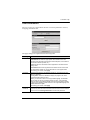
FCC Information
This is an FCC Class A product. In a domestic environment this product may
cause radio interference in which case the user may be required to take
adequate measures.
This equipment has been tested and found to comply with the limits for a Class
A digital device, pursuant to Part 15 of the FCC Rules. These limits are
designed to provide reasonable protection against harmful interference when
the equipment is operated in a commercial environment. This equipment
generates, uses and can radiate radio frequency energy and, if not installed and
used in accordance with the instruction manual, may cause harmful
interference to radio communications. Operation of this equipment in a
residential area is likely to cause harmful interference in which case the user
will be required to correct the interference at his own expense.
RoHS
This product is RoHS compliant.
SJ/T 11364-2006
The following contains information that relates to China.
ii
CN8000 User Manual
User Information
Online Registration
Be sure to register your product at our online support center:
International
http://support.aten.com
North America
http://www.aten-usa.com/product_registration
Telephone Support
For telephone support, call this number:
International
886-2-8692-6959
China
86-10-5255-0110
Japan
81-3-5323-7178
Korea
82-2-467-6789
North America
1-888-999-ATEN ext 4988
United Kingdom
44-8-4481-58923
User Notice
All information, documentation, and specifications contained in this manual
are subject to change without prior notification by the manufacturer. The
manufacturer makes no representations or warranties, either expressed or
implied, with respect to the contents hereof and specifically disclaims any
warranties as to merchantability or fitness for any particular purpose. Any of
the manufacturer's software described in this manual is sold or licensed as is.
Should the programs prove defective following their purchase, the buyer (and
not the manufacturer, its distributor, or its dealer), assumes the entire cost of all
necessary servicing, repair and any incidental or consequential damages
resulting from any defect in the software.
The manufacturer of this system is not responsible for any radio and/or TV
interference caused by unauthorized modifications to this device. It is the
responsibility of the user to correct such interference.
The manufacturer is not responsible for any damage incurred in the operation
of this system if the correct operational voltage setting was not selected prior
to operation. PLEASE VERIFY THAT THE VOLTAGE SETTING IS
CORRECT BEFORE USE.
iii
CN8000 User Manual
Package Contents
The basic CN8000 package consists of:
1 CN8000
2 Custom KVM Cable Sets
1 Custom Console Cable Set
1 USB 2.0 Virtual Media Cable
1 Power Adapter
1 Rack Mount Kit
1 Software CD
1 User Manual*
1 Quick Start Guide
Check to make sure that all the components are present and that nothing got
damaged in shipping. If you encounter a problem, contact your dealer.
Read this manual thoroughly and follow the installation and operation
procedures carefully to prevent any damage to the unit, and/or any of the
devices connected to it.
* Features may have been added to the CN8000 since this manual was printed.
Please visit our website to download the most up-to-date version of the manual.
© Copyright 2007 ATEN® International Co., Ltd.
Manual Part No. PAPE-0288-AT1G
F/W Version: 1.5.143
Manual Date: 2010-07-02
ATEN and the ATEN logo are registered trademarks of ATEN International Co., Ltd. All rights reserved.
All other brand names and trademarks are the registered property of their respective owners.
iv
CN8000 User Manual
Contents
FCC Information . . . . . . . . . . . . . . . . . . . . . . . . . . . . . . . . . . . . . . . . . . . . . ii
RoHS. . . . . . . . . . . . . . . . . . . . . . . . . . . . . . . . . . . . . . . . . . . . . . . . . . . . . . ii
SJ/T 11364-2006. . . . . . . . . . . . . . . . . . . . . . . . . . . . . . . . . . . . . . . . . . . . . ii
User Information . . . . . . . . . . . . . . . . . . . . . . . . . . . . . . . . . . . . . . . . . . . . .iii
Online Registration . . . . . . . . . . . . . . . . . . . . . . . . . . . . . . . . . . . . . . . .iii
Telephone Support . . . . . . . . . . . . . . . . . . . . . . . . . . . . . . . . . . . . . . . .iii
User Notice . . . . . . . . . . . . . . . . . . . . . . . . . . . . . . . . . . . . . . . . . . . . . .iii
Package Contents. . . . . . . . . . . . . . . . . . . . . . . . . . . . . . . . . . . . . . . . . . . iv
About this Manual . . . . . . . . . . . . . . . . . . . . . . . . . . . . . . . . . . . . . . . . . . . xi
Overview . . . . . . . . . . . . . . . . . . . . . . . . . . . . . . . . . . . . . . . . . . . . . . . xi
Conventions . . . . . . . . . . . . . . . . . . . . . . . . . . . . . . . . . . . . . . . . . . . . xii
Terminology. . . . . . . . . . . . . . . . . . . . . . . . . . . . . . . . . . . . . . . . . . . . .xiii
Product Information. . . . . . . . . . . . . . . . . . . . . . . . . . . . . . . . . . . . . . . . . .xiv
1. Introduction
Overview . . . . . . . . . . . . . . . . . . . . . . . . . . . . . . . . . . . . . . . . . . . . . . . . . . . 1
Features and Benefits . . . . . . . . . . . . . . . . . . . . . . . . . . . . . . . . . . . . . . . . . 3
System Requirements. . . . . . . . . . . . . . . . . . . . . . . . . . . . . . . . . . . . . . . . . 6
Remote User Computers. . . . . . . . . . . . . . . . . . . . . . . . . . . . . . . . . . . . 6
Servers . . . . . . . . . . . . . . . . . . . . . . . . . . . . . . . . . . . . . . . . . . . . . . . . . 6
Cables . . . . . . . . . . . . . . . . . . . . . . . . . . . . . . . . . . . . . . . . . . . . . . . . . . 7
Video . . . . . . . . . . . . . . . . . . . . . . . . . . . . . . . . . . . . . . . . . . . . . . . . . . . 8
Operating Systems . . . . . . . . . . . . . . . . . . . . . . . . . . . . . . . . . . . . . . . . 8
Browsers . . . . . . . . . . . . . . . . . . . . . . . . . . . . . . . . . . . . . . . . . . . . . . . . 9
Components . . . . . . . . . . . . . . . . . . . . . . . . . . . . . . . . . . . . . . . . . . . . . . . 10
Front View . . . . . . . . . . . . . . . . . . . . . . . . . . . . . . . . . . . . . . . . . . . . . . 10
Rear View . . . . . . . . . . . . . . . . . . . . . . . . . . . . . . . . . . . . . . . . . . . . . . 11
Custom KVM Cables . . . . . . . . . . . . . . . . . . . . . . . . . . . . . . . . . . . . . . 12
Custom Console Cable . . . . . . . . . . . . . . . . . . . . . . . . . . . . . . . . . . . . 12
2. Hardware Setup
Mounting . . . . . . . . . . . . . . . . . . . . . . . . . . . . . . . . . . . . . . . . . . . . . . . . . . 13
Rack Mounting . . . . . . . . . . . . . . . . . . . . . . . . . . . . . . . . . . . . . . . . . . 13
DIN Rail Mounting . . . . . . . . . . . . . . . . . . . . . . . . . . . . . . . . . . . . . . . . 14
Installation . . . . . . . . . . . . . . . . . . . . . . . . . . . . . . . . . . . . . . . . . . . . . . . . . 15
3. Browser Login
Logging In . . . . . . . . . . . . . . . . . . . . . . . . . . . . . . . . . . . . . . . . . . . . . . . . . 19
Main Webpage Elements . . . . . . . . . . . . . . . . . . . . . . . . . . . . . . . . . . . . . 22
Utility Icons . . . . . . . . . . . . . . . . . . . . . . . . . . . . . . . . . . . . . . . . . . . . . 22
Administrative Function Icons . . . . . . . . . . . . . . . . . . . . . . . . . . . . . . . 22
Remote Console Preview . . . . . . . . . . . . . . . . . . . . . . . . . . . . . . . . . . 23
Exit Macro . . . . . . . . . . . . . . . . . . . . . . . . . . . . . . . . . . . . . . . . . . . . . . 24
Telnet/SSH Viewer . . . . . . . . . . . . . . . . . . . . . . . . . . . . . . . . . . . . . . . 24
User Preferences . . . . . . . . . . . . . . . . . . . . . . . . . . . . . . . . . . . . . . . . . . . 25
v
CN8000 User Manual
4. Administration
Introduction . . . . . . . . . . . . . . . . . . . . . . . . . . . . . . . . . . . . . . . . . . . . . . . . 27
Device Information . . . . . . . . . . . . . . . . . . . . . . . . . . . . . . . . . . . . . . . . . . 28
Network. . . . . . . . . . . . . . . . . . . . . . . . . . . . . . . . . . . . . . . . . . . . . . . . . . . 29
Service Ports. . . . . . . . . . . . . . . . . . . . . . . . . . . . . . . . . . . . . . . . . . . . 29
IP Address. . . . . . . . . . . . . . . . . . . . . . . . . . . . . . . . . . . . . . . . . . . . . . 30
DNS Server . . . . . . . . . . . . . . . . . . . . . . . . . . . . . . . . . . . . . . . . . . . . . 31
Network Transfer Rate . . . . . . . . . . . . . . . . . . . . . . . . . . . . . . . . . . . . 31
Finishing Up . . . . . . . . . . . . . . . . . . . . . . . . . . . . . . . . . . . . . . . . . . . . 31
ANMS . . . . . . . . . . . . . . . . . . . . . . . . . . . . . . . . . . . . . . . . . . . . . . . . . . . . 32
IP Installer . . . . . . . . . . . . . . . . . . . . . . . . . . . . . . . . . . . . . . . . . . . . . . 32
SMTP Settings . . . . . . . . . . . . . . . . . . . . . . . . . . . . . . . . . . . . . . . . . . 33
Log Server. . . . . . . . . . . . . . . . . . . . . . . . . . . . . . . . . . . . . . . . . . . . . . 34
SNMP Server . . . . . . . . . . . . . . . . . . . . . . . . . . . . . . . . . . . . . . . . . . . 34
Syslog Server . . . . . . . . . . . . . . . . . . . . . . . . . . . . . . . . . . . . . . . . . . . 35
DDNS . . . . . . . . . . . . . . . . . . . . . . . . . . . . . . . . . . . . . . . . . . . . . . . . . 35
Disable Local Authentication. . . . . . . . . . . . . . . . . . . . . . . . . . . . . . . . 36
RADIUS Settings. . . . . . . . . . . . . . . . . . . . . . . . . . . . . . . . . . . . . . . . . 36
RADIUS Examples . . . . . . . . . . . . . . . . . . . . . . . . . . . . . . . . . . . . . . . 37
LDAP Settings. . . . . . . . . . . . . . . . . . . . . . . . . . . . . . . . . . . . . . . . . . . 38
CC Management Settings . . . . . . . . . . . . . . . . . . . . . . . . . . . . . . . . . . 39
Security. . . . . . . . . . . . . . . . . . . . . . . . . . . . . . . . . . . . . . . . . . . . . . . . . . . 40
User Station Filters . . . . . . . . . . . . . . . . . . . . . . . . . . . . . . . . . . . . . . . 40
IP Filter / MAC Filter Conflict . . . . . . . . . . . . . . . . . . . . . . . . . . . . . 41
Modifying Filters . . . . . . . . . . . . . . . . . . . . . . . . . . . . . . . . . . . . . . 42
Deleting Filters . . . . . . . . . . . . . . . . . . . . . . . . . . . . . . . . . . . . . . . 42
Login String . . . . . . . . . . . . . . . . . . . . . . . . . . . . . . . . . . . . . . . . . . . . . 42
Account Policy. . . . . . . . . . . . . . . . . . . . . . . . . . . . . . . . . . . . . . . . . . . 43
Login Failures . . . . . . . . . . . . . . . . . . . . . . . . . . . . . . . . . . . . . . . . . . . 44
Encryption . . . . . . . . . . . . . . . . . . . . . . . . . . . . . . . . . . . . . . . . . . . . . . 45
Virtual Media . . . . . . . . . . . . . . . . . . . . . . . . . . . . . . . . . . . . . . . . . . . . 46
Private Certificate . . . . . . . . . . . . . . . . . . . . . . . . . . . . . . . . . . . . . . . . 47
Generating a Self-Signed Certificate . . . . . . . . . . . . . . . . . . . . . . . 47
Obtaining a CA Signed SSL Server Certificate . . . . . . . . . . . . . . . 47
Importing the Private Certificate . . . . . . . . . . . . . . . . . . . . . . . . . . 47
Others . . . . . . . . . . . . . . . . . . . . . . . . . . . . . . . . . . . . . . . . . . . . . . . . . 48
User Management . . . . . . . . . . . . . . . . . . . . . . . . . . . . . . . . . . . . . . . . . . 49
Console Management. . . . . . . . . . . . . . . . . . . . . . . . . . . . . . . . . . . . . . . . 51
Serial Console. . . . . . . . . . . . . . . . . . . . . . . . . . . . . . . . . . . . . . . . . . . 51
Port Property Settings . . . . . . . . . . . . . . . . . . . . . . . . . . . . . . . . . . 52
OOBC . . . . . . . . . . . . . . . . . . . . . . . . . . . . . . . . . . . . . . . . . . . . . . . . . 54
Enable Dial Back . . . . . . . . . . . . . . . . . . . . . . . . . . . . . . . . . . . . . . 54
Sessions . . . . . . . . . . . . . . . . . . . . . . . . . . . . . . . . . . . . . . . . . . . . . . . . . . 57
Customization . . . . . . . . . . . . . . . . . . . . . . . . . . . . . . . . . . . . . . . . . . . . . . 58
vi
CN8000 User Manual
Date/Time . . . . . . . . . . . . . . . . . . . . . . . . . . . . . . . . . . . . . . . . . . . . . . . . . 60
Time Zone . . . . . . . . . . . . . . . . . . . . . . . . . . . . . . . . . . . . . . . . . . . . . . 60
Date . . . . . . . . . . . . . . . . . . . . . . . . . . . . . . . . . . . . . . . . . . . . . . . . . . . 61
Network Time . . . . . . . . . . . . . . . . . . . . . . . . . . . . . . . . . . . . . . . . . . . 61
Maintenance . . . . . . . . . . . . . . . . . . . . . . . . . . . . . . . . . . . . . . . . . . . . . . . 62
Firmware Upgrade. . . . . . . . . . . . . . . . . . . . . . . . . . . . . . . . . . . . . . . . 62
Backup . . . . . . . . . . . . . . . . . . . . . . . . . . . . . . . . . . . . . . . . . . . . . . . . 63
Restore . . . . . . . . . . . . . . . . . . . . . . . . . . . . . . . . . . . . . . . . . . . . . . . . 64
5. The WinClient Viewer
Starting Up . . . . . . . . . . . . . . . . . . . . . . . . . . . . . . . . . . . . . . . . . . . . . . . . 65
Navigation . . . . . . . . . . . . . . . . . . . . . . . . . . . . . . . . . . . . . . . . . . . . . . . . . 66
The WinClient Control Panel. . . . . . . . . . . . . . . . . . . . . . . . . . . . . . . . . . . 67
Control Panel Functions . . . . . . . . . . . . . . . . . . . . . . . . . . . . . . . . . . . 68
Macros. . . . . . . . . . . . . . . . . . . . . . . . . . . . . . . . . . . . . . . . . . . . . . . . . 71
Hotkeys . . . . . . . . . . . . . . . . . . . . . . . . . . . . . . . . . . . . . . . . . . . . . 71
System Macros . . . . . . . . . . . . . . . . . . . . . . . . . . . . . . . . . . . . . . . 77
Video Settings . . . . . . . . . . . . . . . . . . . . . . . . . . . . . . . . . . . . . . . . . . . 80
The Message Board . . . . . . . . . . . . . . . . . . . . . . . . . . . . . . . . . . . . . . 83
The Button Bar. . . . . . . . . . . . . . . . . . . . . . . . . . . . . . . . . . . . . . . . 83
Message Display Panel . . . . . . . . . . . . . . . . . . . . . . . . . . . . . . . . . 84
Compose Panel . . . . . . . . . . . . . . . . . . . . . . . . . . . . . . . . . . . . . . . 84
User List Panel . . . . . . . . . . . . . . . . . . . . . . . . . . . . . . . . . . . . . . . 84
Virtual Media . . . . . . . . . . . . . . . . . . . . . . . . . . . . . . . . . . . . . . . . . . . . 85
Virtual Media Icons . . . . . . . . . . . . . . . . . . . . . . . . . . . . . . . . . . . . 85
Virtual Media Redirection. . . . . . . . . . . . . . . . . . . . . . . . . . . . . . . . 85
Zoom . . . . . . . . . . . . . . . . . . . . . . . . . . . . . . . . . . . . . . . . . . . . . . . . . . 89
The On-Screen Keyboard . . . . . . . . . . . . . . . . . . . . . . . . . . . . . . . . . . 90
Mouse Pointer Type . . . . . . . . . . . . . . . . . . . . . . . . . . . . . . . . . . . . . . 92
Mouse DynaSync Mode . . . . . . . . . . . . . . . . . . . . . . . . . . . . . . . . . . . 92
Automatic Mouse Synchronization (DynaSync). . . . . . . . . . . . . . . 92
Manual Mouse Synchronization. . . . . . . . . . . . . . . . . . . . . . . . . . . 93
Control Panel Configuration . . . . . . . . . . . . . . . . . . . . . . . . . . . . . . . . 94
6. The JavaClient Viewer
Introduction . . . . . . . . . . . . . . . . . . . . . . . . . . . . . . . . . . . . . . . . . . . . . . . . 97
Navigation . . . . . . . . . . . . . . . . . . . . . . . . . . . . . . . . . . . . . . . . . . . . . . . . . 98
The JavaClient Control Panel . . . . . . . . . . . . . . . . . . . . . . . . . . . . . . . . . . 99
Control Panel Functions . . . . . . . . . . . . . . . . . . . . . . . . . . . . . . . . . . 100
Macros. . . . . . . . . . . . . . . . . . . . . . . . . . . . . . . . . . . . . . . . . . . . . . . . 102
Hotkeys . . . . . . . . . . . . . . . . . . . . . . . . . . . . . . . . . . . . . . . . . . . . 102
System Macros . . . . . . . . . . . . . . . . . . . . . . . . . . . . . . . . . . . . . . 103
Search . . . . . . . . . . . . . . . . . . . . . . . . . . . . . . . . . . . . . . . . . . . . . 104
Video Settings . . . . . . . . . . . . . . . . . . . . . . . . . . . . . . . . . . . . . . . . . . 104
Message Board . . . . . . . . . . . . . . . . . . . . . . . . . . . . . . . . . . . . . . . . . 105
Virtual Media . . . . . . . . . . . . . . . . . . . . . . . . . . . . . . . . . . . . . . . . . . . 107
vii
CN8000 User Manual
Zoom . . . . . . . . . . . . . . . . . . . . . . . . . . . . . . . . . . . . . . . . . . . . . . . . . 107
The On-Screen Keyboard . . . . . . . . . . . . . . . . . . . . . . . . . . . . . . . . . 108
Mouse Pointer Type . . . . . . . . . . . . . . . . . . . . . . . . . . . . . . . . . . . . . 108
Mouse DynaSync Mode . . . . . . . . . . . . . . . . . . . . . . . . . . . . . . . . . . 109
Control Panel Configuration . . . . . . . . . . . . . . . . . . . . . . . . . . . . . . . 109
7. The Log File
The Log File Screen . . . . . . . . . . . . . . . . . . . . . . . . . . . . . . . . . . . . . . . . 111
8. The Log Server
Installation. . . . . . . . . . . . . . . . . . . . . . . . . . . . . . . . . . . . . . . . . . . . . . . . 113
Starting Up . . . . . . . . . . . . . . . . . . . . . . . . . . . . . . . . . . . . . . . . . . . . . . . 114
The Menu Bar . . . . . . . . . . . . . . . . . . . . . . . . . . . . . . . . . . . . . . . . . . . . . 115
Configure. . . . . . . . . . . . . . . . . . . . . . . . . . . . . . . . . . . . . . . . . . . . . . 115
Events . . . . . . . . . . . . . . . . . . . . . . . . . . . . . . . . . . . . . . . . . . . . . . . . 116
Search . . . . . . . . . . . . . . . . . . . . . . . . . . . . . . . . . . . . . . . . . . . . . 116
Maintenance . . . . . . . . . . . . . . . . . . . . . . . . . . . . . . . . . . . . . . . . 117
Options . . . . . . . . . . . . . . . . . . . . . . . . . . . . . . . . . . . . . . . . . . . . . . . 118
Help. . . . . . . . . . . . . . . . . . . . . . . . . . . . . . . . . . . . . . . . . . . . . . . . . . 118
The Log Server Main Screen . . . . . . . . . . . . . . . . . . . . . . . . . . . . . . . . . 119
Overview . . . . . . . . . . . . . . . . . . . . . . . . . . . . . . . . . . . . . . . . . . . . . . 119
The List Panel . . . . . . . . . . . . . . . . . . . . . . . . . . . . . . . . . . . . . . . . . . 120
The Tick Panel . . . . . . . . . . . . . . . . . . . . . . . . . . . . . . . . . . . . . . . . . 120
9. AP Operation
Introduction . . . . . . . . . . . . . . . . . . . . . . . . . . . . . . . . . . . . . . . . . . . . . . . 121
The Windows Client AP . . . . . . . . . . . . . . . . . . . . . . . . . . . . . . . . . . . . . 121
Installation . . . . . . . . . . . . . . . . . . . . . . . . . . . . . . . . . . . . . . . . . . . . . 121
Starting Up . . . . . . . . . . . . . . . . . . . . . . . . . . . . . . . . . . . . . . . . . . . . 122
The Windows Client Connection Screen. . . . . . . . . . . . . . . . . . . . . . 123
Logging In . . . . . . . . . . . . . . . . . . . . . . . . . . . . . . . . . . . . . . . . . . . . . 124
The Administrator Utility . . . . . . . . . . . . . . . . . . . . . . . . . . . . . . . . . . . . . 126
Device Information . . . . . . . . . . . . . . . . . . . . . . . . . . . . . . . . . . . . . . 126
Network . . . . . . . . . . . . . . . . . . . . . . . . . . . . . . . . . . . . . . . . . . . . . . . 127
ANMS . . . . . . . . . . . . . . . . . . . . . . . . . . . . . . . . . . . . . . . . . . . . . . . . 128
Security . . . . . . . . . . . . . . . . . . . . . . . . . . . . . . . . . . . . . . . . . . . . . . . 129
User Management. . . . . . . . . . . . . . . . . . . . . . . . . . . . . . . . . . . . . . . 130
Console Management . . . . . . . . . . . . . . . . . . . . . . . . . . . . . . . . . . . . 131
Serial Console . . . . . . . . . . . . . . . . . . . . . . . . . . . . . . . . . . . . . . . 131
Customization . . . . . . . . . . . . . . . . . . . . . . . . . . . . . . . . . . . . . . . . . . 133
Date/Time . . . . . . . . . . . . . . . . . . . . . . . . . . . . . . . . . . . . . . . . . . . . . 134
Maintenance . . . . . . . . . . . . . . . . . . . . . . . . . . . . . . . . . . . . . . . . . . . 135
The Java Client AP . . . . . . . . . . . . . . . . . . . . . . . . . . . . . . . . . . . . . . . . . 136
Starting Up . . . . . . . . . . . . . . . . . . . . . . . . . . . . . . . . . . . . . . . . . . . . 136
The Java Client Connection Screen . . . . . . . . . . . . . . . . . . . . . . . . . 137
Logging In . . . . . . . . . . . . . . . . . . . . . . . . . . . . . . . . . . . . . . . . . . . . . 137
viii
CN8000 User Manual
10.LDAP Server Configuration
Introduction . . . . . . . . . . . . . . . . . . . . . . . . . . . . . . . . . . . . . . . . . . . . . . . 139
Install the Windows 2003 Support Tools. . . . . . . . . . . . . . . . . . . . . . . . . 139
Install the Active Directory Schema Snap-in . . . . . . . . . . . . . . . . . . . . . . 140
Create a Start Menu Shortcut Entry . . . . . . . . . . . . . . . . . . . . . . . . . . . . 140
Extend and Update the Active Directory Schema . . . . . . . . . . . . . . . . . . 141
Creating a New Attribute . . . . . . . . . . . . . . . . . . . . . . . . . . . . . . . . . . 141
Extending the Object Class With the New Attribute . . . . . . . . . . . . . 142
Editing Active Directory Users . . . . . . . . . . . . . . . . . . . . . . . . . . . . . . 144
Type 1 . . . . . . . . . . . . . . . . . . . . . . . . . . . . . . . . . . . . . . . . . . . . . 144
Permission String Characters . . . . . . . . . . . . . . . . . . . . . . . . . . . 148
OpenLDAP . . . . . . . . . . . . . . . . . . . . . . . . . . . . . . . . . . . . . . . . . . . . . . . 151
OpenLDAP Server Installation . . . . . . . . . . . . . . . . . . . . . . . . . . . . . 151
OpenLDAP Server Configuration . . . . . . . . . . . . . . . . . . . . . . . . . . . 152
Starting the OpenLDAP Server . . . . . . . . . . . . . . . . . . . . . . . . . . . . . 153
Customizing the OpenLDAP Schema . . . . . . . . . . . . . . . . . . . . . . . . 154
LDAP DIT Design and LDIF File . . . . . . . . . . . . . . . . . . . . . . . . . . . . 155
LDAP Data Structure . . . . . . . . . . . . . . . . . . . . . . . . . . . . . . . . . . 155
DIT Creation . . . . . . . . . . . . . . . . . . . . . . . . . . . . . . . . . . . . . . . . 156
Using the New Schema . . . . . . . . . . . . . . . . . . . . . . . . . . . . . . . . . . . 158
Appendix
Safety Instructions. . . . . . . . . . . . . . . . . . . . . . . . . . . . . . . . . . . . . . . . . . 159
General . . . . . . . . . . . . . . . . . . . . . . . . . . . . . . . . . . . . . . . . . . . . . . . 159
Rack Mounting . . . . . . . . . . . . . . . . . . . . . . . . . . . . . . . . . . . . . . . . . 161
Technical Support . . . . . . . . . . . . . . . . . . . . . . . . . . . . . . . . . . . . . . . . . . 162
International. . . . . . . . . . . . . . . . . . . . . . . . . . . . . . . . . . . . . . . . . . . . 162
North America . . . . . . . . . . . . . . . . . . . . . . . . . . . . . . . . . . . . . . . . . . 162
IP Address Determination . . . . . . . . . . . . . . . . . . . . . . . . . . . . . . . . . . . . 163
IP Installer . . . . . . . . . . . . . . . . . . . . . . . . . . . . . . . . . . . . . . . . . . . . . 163
Browser . . . . . . . . . . . . . . . . . . . . . . . . . . . . . . . . . . . . . . . . . . . . . . . 164
AP Windows Client . . . . . . . . . . . . . . . . . . . . . . . . . . . . . . . . . . . . . . 164
IPv6 . . . . . . . . . . . . . . . . . . . . . . . . . . . . . . . . . . . . . . . . . . . . . . . . . . . . . 165
Link Local IPv6 Address . . . . . . . . . . . . . . . . . . . . . . . . . . . . . . . . . . 165
IPv6 Stateless Autoconfiguration . . . . . . . . . . . . . . . . . . . . . . . . . . . 166
Port Forwarding. . . . . . . . . . . . . . . . . . . . . . . . . . . . . . . . . . . . . . . . . . . . 167
Keyboard Emulation . . . . . . . . . . . . . . . . . . . . . . . . . . . . . . . . . . . . . . . . 168
PPP Modem Operation . . . . . . . . . . . . . . . . . . . . . . . . . . . . . . . . . . . . . . 169
Basic Setup . . . . . . . . . . . . . . . . . . . . . . . . . . . . . . . . . . . . . . . . . . . . 169
Connection Setup Example (Windows XP) . . . . . . . . . . . . . . . . . . . . 170
Trusted Certificates . . . . . . . . . . . . . . . . . . . . . . . . . . . . . . . . . . . . . . . . . 171
Overview . . . . . . . . . . . . . . . . . . . . . . . . . . . . . . . . . . . . . . . . . . . . . . 171
Installing the Certificate . . . . . . . . . . . . . . . . . . . . . . . . . . . . . . . . . . . 172
Certificate Trusted . . . . . . . . . . . . . . . . . . . . . . . . . . . . . . . . . . . . . . . 173
ix
CN8000 User Manual
Self-Signed Private Certificates . . . . . . . . . . . . . . . . . . . . . . . . . . . . . . . 175
Examples . . . . . . . . . . . . . . . . . . . . . . . . . . . . . . . . . . . . . . . . . . . . . 175
Importing the Files. . . . . . . . . . . . . . . . . . . . . . . . . . . . . . . . . . . . . . . 175
Troubleshooting . . . . . . . . . . . . . . . . . . . . . . . . . . . . . . . . . . . . . . . . . . . 176
General Operation. . . . . . . . . . . . . . . . . . . . . . . . . . . . . . . . . . . . . . . 176
Windows . . . . . . . . . . . . . . . . . . . . . . . . . . . . . . . . . . . . . . . . . . . . . . 177
Java. . . . . . . . . . . . . . . . . . . . . . . . . . . . . . . . . . . . . . . . . . . . . . . . . . 178
Sun Systems . . . . . . . . . . . . . . . . . . . . . . . . . . . . . . . . . . . . . . . . . . . 179
Mac Systems. . . . . . . . . . . . . . . . . . . . . . . . . . . . . . . . . . . . . . . . . . . 180
The Log Server . . . . . . . . . . . . . . . . . . . . . . . . . . . . . . . . . . . . . . . . . 180
Additional Mouse Synchronization Procedures . . . . . . . . . . . . . . . . . . . 181
Windows:. . . . . . . . . . . . . . . . . . . . . . . . . . . . . . . . . . . . . . . . . . . . . . 181
Sun / Linux . . . . . . . . . . . . . . . . . . . . . . . . . . . . . . . . . . . . . . . . . . . . 182
Supported KVM Switches . . . . . . . . . . . . . . . . . . . . . . . . . . . . . . . . . . . . 183
Virtual Media Support . . . . . . . . . . . . . . . . . . . . . . . . . . . . . . . . . . . . . . . 183
WinClient ActiveX Viewer / WinClient AP . . . . . . . . . . . . . . . . . . . . . 183
Java Applet Viewer / Java Client AP. . . . . . . . . . . . . . . . . . . . . . . . . 183
Administrator Login Failure. . . . . . . . . . . . . . . . . . . . . . . . . . . . . . . . . . . 184
Specifications . . . . . . . . . . . . . . . . . . . . . . . . . . . . . . . . . . . . . . . . . . . . . 185
About SPHD Connectors . . . . . . . . . . . . . . . . . . . . . . . . . . . . . . . . . . . . 186
Limited Warranty. . . . . . . . . . . . . . . . . . . . . . . . . . . . . . . . . . . . . . . . . . . 186
x
CN8000 User Manual
About this Manual
This User Manual is provided to help you get the most from your c/c system.
It covers all aspects of installation, configuration and operation. An overview
of the information found in the manual is provided below.
Overview
Chapter 1, Introduction, introduces you to the CN8000 System. Its
purpose, features and benefits are presented, and its front and back panel
components are described.
Chapter 2, Hardware Setup, provides step-by-step instructions for setting
up your installation, and explains some basic operation procedures.
Chapter 3, Browser Login, describes how to log into the CN8000 with a
browser, and explains the functions of the icons and buttons that appear on the
opening page.
Chapter 4, Administration, explains the administrative procedures that are
employed to configure the CN8000’s working environment, as well as how to
operate the CN8000 from the local console.
Chapter 5, The WinClient Viewer, explains how to connect to the
CN8000 with the Windows Client software, and describes how to use the OSD
to access and control the computers connected to the switch.
Chapter 6, The JavaClient Viewer, describes how to connect to the
CN8000 with the Java Applet software, and explains how to use the OSD to
access and control the computers connected to the switch.
Chapter 7, The Log File, shows how to use the log file utility to view the
events that take place on the CN8000.
Chapter 8, The Log Server, explains how to install and configure the Log
Server.
Chapter 9, AP Operation, describes how to operate the CN8000 using
Windows and Java programs, rather than with the browser method.
Chapter 10, LDAP Server Configuration, explains how to configure the
CN8000 for LDAP / LDAPS authentication and authorization with Active
Directory or OpenLDAP.
An Appendix, provides specifications and other technical information
regarding the CN8000.
xi
CN8000 User Manual
Conventions
This manual uses the following conventions:
Monospaced
[]
Indicates text that you should key in.
Indicates keys you should press. For example, [Enter] means to
press the Enter key. If keys need to be chorded, they appear
together in the same bracket with a plus sign between them:
[Ctrl+Alt].
1.
Numbered lists represent procedures with sequential steps.
♦
Bullet lists provide information, but do not involve sequential steps.
→
Indicates selecting the option (on a menu or dialog box, for
example), that comes next. For example, Start → Run means to
open the Start menu, and then select Run.
Indicates critical information.
xii
CN8000 User Manual
Terminology
Throughout the manual we make reference to the terms Local and Remote in
regard to the operators and equipment deployed in a CN8000 installation.
Depending on the point of view, users and servers can be considered Local
under some circumstances, and Remote under others:
Switch’s Point of View
Remote users – We refer to a user as a Remote user when we think of
him as someone who logs into the switch over the net from a location
that is remote from the switch.
Local Console – The keyboard mouse and monitor connected directly
to the switch.
Servers – The servers attached to the switch via custom KVM cables.
User’s Point of View
Local client users – We refer to a user as a Local client user when we
think of him as sitting at his computer performing operations on the
servers connected to the switch that is remote from him.
Remote servers – We refer to the servers as Remote servers when we
think of them from the Local Client User’s point of view – since,
although they are locally attached to the switch, they are remote from
him.
When we describe the overall system architecture we are usually speaking
from the switch’s point of view – in which case the users are considered
remote. When we speak about operations users perform via the browser,
viewers, and AP programs over the net, we are usually speaking from the user’s
point of view – in which case the switch and the servers connected to it are
considered remote.
xiii
CN8000 User Manual
Product Information
For information about all ATEN products and how they can help you connect
without limits, visit ATEN on the Web or contact an ATEN Authorized
Reseller. Visit ATEN on the Web for a list of locations and telephone numbers:
International
http://www.aten.com
North America
http://www.aten-usa.com
xiv
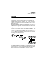
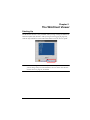
Chapter 1
Introduction
Overview
The CN8000 is a control unit that provides “over-IP” capability to KVM
switches that do not have built in over-IP functionality. It allows operators to
monitor and access their computers from remote locations using a standard
Internet browser or Windows and Java based application programs. The
CN8000 connects to the Internet, an Intranet, LAN, or WAN using industry
standard Cat 5e cable, then uses a custom KVM cable to connect to a local
KVM switch or server.
Because the CN8000 uses TCP/IP for its communications protocol, the server
or KVM switch it is connected to can be accessed from any computer on the
Net – whether that computer is located down the hall, down the street, or halfway around the world.
Operators at remote locations connect to the CN8000 via its IP address. Once
a connection has been established and authorization granted, the remote
computer can exchange keyboard, video and mouse signals with the server (or
servers on a KVM switch installation), just as if they were physically present
and working on the equipment directly.
KVM Switch
The CN8000 expands on previous models by providing a dedicated RS-232
port for modem access or serial console management, a PON port to attach a
Power Over the NET™ device and USB 2.0 virtual media capability.
1
CN8000 User Manual
With its advanced security features, the CN8000 is the fastest, most reliable,
most cost effective way to remotely access and manage widely distributed
multiple computer installations.
The Administrator and Client software included with the CN8000 make it easy
to install, maintain, and operate. System administrators can handle a multitude
of tasks with ease - from installing and running GUI applications, to BIOS level
troubleshooting, routine monitoring, concurrent maintenance, system
administration, rebooting and even pre-booting functions.
The Administrator Utility is available in a browser-based version as well as
Windows-based and Java application versions. The utility is used to configure
the system; limit access from remote computers; manage users; and maintain
the system with firmware and software module updates.
A Windows Client Viewer and a Java Applet Viewer are available for browser
access, while Windows Client AP and Java Client AP programs are provided
for non-browser GUI access. They allow IP connection and login from
anywhere on the net. Inclusion of a Java-based client ensures that the CN8000
is platform independent, and is able to work with practically all operating
systems.
The client software allows access to, and control of, the connected servers.
Once an operator successfully connects and logs in, his screen displays what is
running on the remote unit attached to the CN8000 (a KVM OSD display, a
server's desktop, or a running program, for example) and he can control it from
his console just as if he were there.
The Log Server records all the events that take place on selected CN8000 units
for the administrator to analyze.
Your CN8000 investment is protected through the ability of its firmware to be
upgraded over the internet. You can stay current with the latest functionality
improvements by downloading firmware update files from our website as they
become available, and then using the utility to quickly and conveniently
perform the upgrade.
2
1. Introduction
Features and Benefits
The features and benefits provided by a CN8000 deployment are described in
the following table:
Features
Over-IP
Capability for
Legacy KVM
Switches
Benefits
Protects your original KVM switch investment. No need to
purchase new KVM switches to achieve the benefits of over-IP
connectivity.
Configuration and An easy-to-navigate graphical user interface makes for convenient,
Operation Ease
intuitive configuration and operation. Web-based Windows and
Java implementations allow the remote equipment to be controlled
from industry-standard web browsers. Windows and Java AP client
software – using the same, convenient, GUI – are also included to
provide access where a browser environment is not desired.
Superior Video
With its enhanced fps throughput for crisp responsive video display,
the CN8000 offers resolutions of up to 1600 x 1200 @ 60Hz;
vibrant 24-bit color depth for rich remote session display. The
remote desktop can appear full-screen, or in a window. In fullscreen mode the remote desktop display scales to the user’s
monitor display size.
Virtual Media
USB 1.1 and 2.0 devices (Floppy drives, CDROMs, Flash drives,
etc.), folders, and image files on a user’s local system, appear and
act as if they were installed on the remote server, for ease and
convenience when performing software installation and system
updates across the entire Installation.
Virtual Remote
Desktop
On-screen keyboard with multilanguage support
Exit Macros support
BIOS-level access
Smart Card / CAC To meet advanced security requirements, the CN8000’s Virtual
Reader Support
Media function allows a Smart Card / CAC reader on a user’s local
system to be mapped to a remote server.
Low Bandwidth
Optimization
Bandwidth optimization via grayscaling and video quality settings
allow maximum data throughput in low bandwidth situations. PPP
modem dialup support ensures reliable connectivity for out-ofband, and low bandwidth situations.
Multi-Platform /
Multi-Protocol
Support
Windows and Java client software ensures that the CN8000 and
the equipment that connects to it can be accessed from most of the
operating systems in use today (Windows, Linux, Unix, Sun, Mac).
The CN8000 also supports a broad range of communication
protocols, such as TCP/IP, HTTP, HTTPS, UDP, DHCP, SSL, ARP,
DNS, ICMP, CHAP, PPP, 10Base-T, 100Base-T
3
CN8000 User Manual
Features
Benefits
On-Screen
Keyboard
The CN8000 supports multiple keyboard language input – including
English, French, German, Italian, Spanish, Japanese, Korean, and
Traditional Chinese. There is no need to have a separate keyboard
for each language – you can input key data in any of these
languages with the CN8000's convenient on-screen keyboard.
Multi-Users /
Multi-Logins
The CN8000 supports up to 64 user accounts, and allows up to 32
concurrent user logins for single-bus access.
Message Board
To alleviate the possibility of access conflicts that may result from
multiple user logins, and facilitate communication among the
logged-in users, a message board – similar to an Internet chat
program – allows users to communicate with each other, and
provides mechanisms for a user to take exclusive control of the
KVM functions.
Advanced
Security
Advanced security features include password protection –
Multi-Keyboard
Language
Support /
whereby a valid username and password must be given before
the client software will run – and advanced encryption
technologies, such as secure 128-bit SSL.
Flexible encryption design allows users to choose any
combination of 56-bit DES, 168-bit 3DES 256-bit AES, 128-bit
RC4, or Random for independent KB/Mouse, video, and virtual
media data encryption.
Support for IP/MAC Filter
Supports strong password protection
Private CA
External
Authentication
Support
In addition to its own security protection, the CN8000 allows you to
set up log in authentication and authorization management from a
external sources such as RADIUS, LDAP, LDAPS, and MS Active
Directory.
Event Logging
The CN8000 can record all the events that take place on it and
write them to a searchable database. Administrators and selected
users can search for events containing specific words or strings
and retrieve them according to date and order of significance.
Console
Management
Serial console management – serial terminal access. Access the
CN8000 via a built-in serial viewer, or via third party software
(such as PuTTY) for Telnet and SSH sessions.
Out of Band Support – via dial up modem support. Access the
CN8000 through its RS-232 port using a dial-up connection.
Upgradeable
Firmware over
the Internet
4
No need to add yet another cable to your installation – stay current
with the latest functionality improvements and updates, all over the
Internet.
1. Introduction
Features
Remote Power
Control
Benefits
You can add a PON (Power Over the NET™) power management
unit and remotely control the power status of devices on your
installation, including monitoring their current status, as well as
turning servers On, Off and Rebooting them.
Mouse DynaSync No need to re-sync your mouse – Mouse DynaSync provides
automatic locked-in synching of the remote and local mouse
pointers – eliminating the need to constantly resync the two
movements. Your local console mouse movement becomes the
remote unit’s mouse movement.
Full-Screen or
Sizable Remote
Desktop Window
Get a full screen even if your monitor’s resolution is lower than the
remote computer’s resolution. In full-screen mode the remote
desktop display scales to the user’s monitor display size. Supports
up to 1600 x 1200 @ 60Hz; 24-bit color depth for remote sessions.
DDNS
Allows the mapping of a dynamic IP address assigned by a DHCP
server to a hostname.
End session
Administrators can terminate running sessions
5
CN8000 User Manual
System Requirements
Remote User Computers
Remote user computers (also referred to as client computers) are the ones the
users log into the switch with from remote locations over the internet (see
Terminology, page xiii). The following equipment must be installed on these
computers:
For best results we recommend that the computers used to access the
switch have at least a P III 1 GHz processor, with their screen resolution
set to 1024 x 768.
Browsers must support 128 bit SSL encryption.
For best results, a network transfer speed of at least 128 kbps is
recommended.
For the Windows Client AP, at least 25 MB of memory must be available
after installation.
For the Java Client AP, the latest version of Sun's Java Runtime
Environment (JRE) must be installed, and at least 55 MB of memory must
be available after installation.
For the browser-based WinClient Viewer, at least 60 MB of memory must
be available after installation.
For the browser-based Java Applet Viewer the latest version of Sun's Java
Runtime Environment (JRE) must be installed, and at least 130 MB of
memory must be available after installation.
For the Log Server, you must have the Microsoft Jet OLEDB 4.0 or higher
driver installed.
Servers
Servers are the computers connected to the switch via KVM Cables (see
Terminology, page xiii). The following equipment must be installed on these
servers:
A VGA, SVGA or multisync port
For USB KVM Cable Connections: a Type A USB port and USB host
controller
For PS/2 KVM Cable Connections: 6-pin Mini-DIN keyboard and mouse
ports
6
1. Introduction
Cables
Two custom KVM cable sets (1 USB; 1 PS/2) to link the CN8000 to a
server or KVM switch are provided with this package.
Custom KVM cable sets are available in various lengths, as shown in the
table below:
Cable Type
PS/2
USB
Length
CS Part Number
1.2 m
2L-5201P
1.8 m
2L-5202P
1.8 m
2L-5702P
3.0 m
2L-5203P
6.0 m
2L-5206P
1.2 m
2L-5201U
1.8 m
2L-5202U
3.0 m
2L-5203U
5.0 m
2L-5205U
To purchase additional cable sets, contact your dealer.
One custom Console cable set to link the CN8000 to a local console is
provided with this package.
Note: This cable set has been designed to operate with either PS/2 or USB
consoles.
A USB 2.0 cable for use with the Virtual Media function (see Virtual
Media Port, page 11) is provided with this package.
Cat 5e or higher Ethernet cable (not provided with this package), should be
used to connect the CN8000 to the LAN, WAN, or Internet.
7
CN8000 User Manual
Video
Only the following non-interlaced video signals are supported:
Resolution
640 x 480
Refresh Rates
60, 72, 75, 85, 90, 100, 120
720 x 400
70
800 x 600
56, 60, 72, 75, 85, 90, 100, 120
1024 x 768
60, 70, 75, 85, 90, 100
1152 x 864
60, 70, 75, 85
1280 x 720
60
1280 x 1024
60, 70, 75, 85
1600 x 1200
60
Operating Systems
Supported operating systems for remote user computers that log into the
CN8000 include Windows 2000 and higher, and other systems capable of
running Sun's Java Runtime Environment (JRE) 6, Update 3, or higher
(Linux, Mac, Sun, etc.).
Supported operating systems for servers that connect to the CN8000 are
shown in the table, below:
OS
Windows
Linux
Version
2000 and higher
RedHat
7.1 and higher
Fedora
Core 5 and higher
SuSE
9.0 and higher
Mandriva (Mandrake) 9.0 and higher
UNIX
Novell
8
AIX
4.3 and higher
FreeBSD
3.51 and higher
Sun
Solaris 8 and higher
Netware
5.0 and higher
Mac
OS 9 and higher
DOS
6.2 and higher
1. Introduction
Browsers
Supported browsers for users that log into the CN8000 include the following:
Browser
Version
IE
6 and higher
Firefox
1.5 and higher
Mozilla
1.7 and higher
Safari*
2.0 and higher
Opera
9.0 and higher
Netscape
8.1 and higher
* See Mac Systems, page 180, for further information regarding Safari.
9
CN8000 User Manual
Components
Front View
1
2 3
4 5
No.
Component
Description
1
LAN Port
The Cat 5e cable that connects the CN8000 to the LAN, WAN,
or Internet plugs in here.
2
Firmware
Upgrade/Reset
Switch
1. Pressing and releasing this switch performs a CN8000
system reset. (See Erratic operation, page 176.)
2. Pressing and holding this switch for more than three
seconds returns the CN8000 to its factory default
configuration settings.
3. Pressing and holding this switch while powering on the
switch returns the CN8000 to its factory default firmware
level. This operation should only be performed in the event
of a firmware upgrade failure that results in the device
becoming inoperable.
Note: This switch is recessed and must be pushed with a thin
object - such as the end of a paper clip, or a ballpoint pen.
10
3
10/100 Mbps
LED
The LED lights ORANGE to indicate 10 Mbps data
transmission speed. It lights GREEN to indicate 100 Mbps
data transmission speed.
4
Link LED
Flashes GREEN to indicate that a Client program is accessing
the device.
5
Power LED
Lights ORANGE when the CN8000 is powered up and ready
to operate.
1. Introduction
Rear View
1 2
No.
Component
3
4
5
6
Description
1
Power Jack
The power adapter cable plugs in here.
2
Virtual Media Port
The cable that connects the CN8000 to a USB port on your
server or KVM switch plugs in here. See Virtual Media,
page 85, for virtual media details.
3
PC/KVM Port
The KVM cable (supplied with this package) that links the
CN8000 to your server or KVM switch plugs in here.
4
Console Port
The CN8000 can be accessed via a local console as well
as over the Net. The cable for the local console (keyboard,
monitor, and mouse) plugs in here. The console can use
either a PS/2 or USB keyboard and mouse. Each
connector is color coded and marked with an appropriate
icon to indicate itself.
5
PON Port
This port is made available for use with a Power over the
NET™ remote power management module. If you connect
a PON device, its cable plugs in here. Refer to the User
Manual that came with the PON device for operation
details.
6
RS-232 Port
This serial port is provided for:
1. Serial console management (see Console
Management, page 51 for details); or
2. Out-of-band modem operation (see OOBC, page 54 for
details).
11
CN8000 User Manual
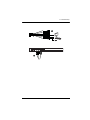
Custom KVM Cables
1
2
No.
Description
1
For use with PS/2 configuration servers or KVM switches.
2
For use with USB configuration servers or KVM switches.
Note: The advantage of using a USB cable is that it allows automatic lockedin mouse synchronization. See Mouse DynaSync Mode, page 92, for
details.
Custom Console Cable
USB Keyboard
USB Mouse
Video
PS/2 Keyboard
PS/2 Mouse
Note: You can use any combination of keyboard and mouse connections. For
example, you can use a PS/2 keyboard with a USB mouse.
12
Chapter 2
Hardware Setup
1. Important safety information regarding the placement of this
device is provided on page 159. Please review it before
proceeding.
2. Make sure that the power to any device that you connect to the
installation has been turned off. You must unplug the power
cords of any computers that have the Keyboard Power On
function.
Mounting
Rack Mounting
For convenience and flexibility, the CN8000 can be mounted on a system rack.
To rack mount the unit do the following:
1. Remove the two original screws from the bottom of the unit (near the rear
of the unit).
2. Using the screws provided with the rack mount kit, screw the mounting
bracket into the CN8000 – as shown in the diagram below.
Phillips hex head
M3 x 8
13
CN8000 User Manual
3. Screw the bracket into any convenient location on the rack.
Note: Rack screws are not provided. Use screws that are appropriate for
your rack.
DIN Rail Mounting
To mount the CN8000 on a DIN rail:
1. Screw the mounting bracket to the back of the CN8000 as described in
steps 1 and 2 of the wall mounting procedure.
2. Use the larger screws supplied with the Rack Mount Kit to screw the DIN
rail brackets to the mounting bracket – as shown in the diagram, below:
3. Hang the unit on the DIN rail.
14
2. Hardware Setup
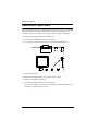
Installation
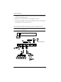
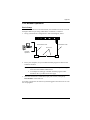
To install the CN8000, refer to the installation diagrams on the next two pages
(the numbers correspond to the numbers of the steps), and do the following:
1. Use the Console cable provided with this package to connect the
CN8000’s Console port, to the local console keyboard, monitor and
mouse.
Note: 1. The Console cable comes with connectors for both PS/2 and USB
mice and keyboards – use the ones appropriate for your
installation.
2. You can use any combination of keyboard and mouse
connections. For example, you can use a PS/2 keyboard with a
USB mouse.
2. Use the KVM cable provided with this package to connect the CN8000’s
PC/KVM port, to the keyboard, video and mouse ports of the server or
KVM switch that you are installing.
Note: 1. The diagram shows a connection to a KVM switch with PS/2
mouse and keyboard ports using a PS/2 KVM cable set. The
CN8000 can also connect to a server or KVM switch that uses a
USB connection by using a USB KVM cable set. See Cables,
page 7, for cable option information.
2. If you are using a PS/2 configuration KVM cable, refer to
page 181 for mouse pointer synchronization information.
3. If you are using a USB configuration KVM cable, see Mouse
DynaSync Mode, page 92, for mouse pointer synchronization
information.
4. The CN8000’s virtual media features may not be supported,
depending on the functionality of the cascaded KVM switch (see
Supported KVM Switches, page 183).
3. (Optional) If you want to use the virtual media function (see Virtual
Media, page 85), use the USB 2.0 Virtual Media Cable provided with this
package to connect a USB port on the server to the CN8000's Virtual
Media port.
4. (Optional) If you want to connect a PON device for remote power
management, plug its cable into the PON port.
15
CN8000 User Manual
5. (Optional) If you want to connect a serial console device or modem, plug
its cable into the RS-232 port.
6. Plug the LAN or WAN cable into the CN8000's LAN port.
7. Plug the power adapter cable into the CN8000's power jack, then plug the
power adapter into an AC power source.
This completes the hardware installation, and you are ready to start up.
Note: When starting up, be sure to first power on the CN8000, then power on
the server or KVM switch.
6
5
Modem
4
Serial Console Device
(Router, Switch, Sunfire V100,....)
PN0108
7
3
2
KVM Switch
16
1
2. Hardware Setup
1
2
17
CN8000 User Manual
This Page Intentionally Left Blank
18
Chapter 3
Browser Login
The CN8000 can be accessed either from an internet type browser, via
Windows and Java application (AP) program, or by PPP modem dial-in. The
next several chapters describe browser-based operations; AP access is
discussed in Chapter 9; PPP modem login is discussed on page 169.
Logging In
To operate the CN8000 from an Internet browser, begin by logging in:
1. Open your browser and specify the IP address of the CN8000 you want to
access in the browser's URL location bar.
Note: 1. For security purposes, a login string may have been set by the
administrator. If so, you must include a forward slash and the
login string along with the IP address when you log in. For
example:
192.168.0.100/CN8000
If you don't know the IP address and login string, ask your
Administrator.
2. If you are the administrator, and are logging in for the first time,
the various ways to determine the CN8000's IP address are
described in the Appendix on page 163.
(Continues on next page.)
19
CN8000 User Manual
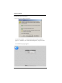
(Continued from previous page.)
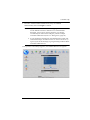
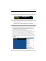
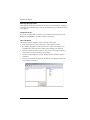
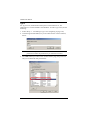
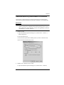
2. A Security Alert dialog box appears.
Accept the certificate – it can be trusted. (See Trusted Certificates,
page 171, for details.) If a second certificate appears, accept it as well.
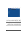
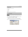
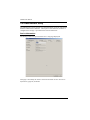
The CN8000 login page appears:
20
3. Browser Login
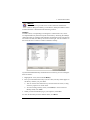
3. Provide a valid Username and Password (set by the CN8000
administrator), then click Login to continue.
Note: 1. If you are the administrator, and are logging in for the first time,
use the default Username: administrator; and the default
Password: password. For security purposes, we strongly
recommend you remove these and give yourself a unique
Username and Password (see User Management, page 49).
2. If you supplied an invalid login, the authentication routine will
return this message: Invalid Username or Password. Please try
again. If you see this message, log in again being careful with the
Username and Password.
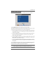
After you have successfully logged in, the CN8000 Main Screen appears:
21
CN8000 User Manual
Main Webpage Elements
The Main page consists of user access icons arranged vertically down the left
side; administrative function icons arranged across the top; a Remote Console
Preview window with an icon to launch the Java or WinClient Viewer
displayed in the center; and an Exit Macro list box just below the Remote
Console Preview
Note: If a user doesn’t have permission to perform a particular activity, the
icon for that activity doesn’t appear. See User Management, page 49,
for permission details.
Utility Icons
The icons arranged down the left side perform the following functions:
Icon
Purpose
Remote Console: Clicking this icon closes whatever is displayed on
the Main Screen, and brings back the Remote Console Preview.
(See Remote Console Preview, page 23.)
Power Management: If a Power over the NET™ module is connected
to your installation, and if you have the proper permission (see User
Management, page 49), clicking this icon will bring up its interface.
Log: All the events that take place on the CN8000 are recorded in a log
file. If you have the proper permission (see User Management, page 49),
clicking this icon displays the contents of the log file. The Log File is
discussed in Chapter 7.
User Preferences: Click this icon to set up your own, individual,
browsing environment. The switch stores a separate configuration record
for each user profile, and sets up the browser configuration according to
the Username that you key into the Login dialog box. (See User
Preferences, page 25.)
Logout: Click this icon to log out and end your CN8000 session.
It is important to log out when you end your session. Otherwise, you must
wait until the timeout setting has expired before the CN8000 can be
accessed again. (See Timeout, page 58.)
Administrative Function Icons
The icons arranged horizontally across the top of the page are linked to the
administration utilities, which are used to configure the CN8000. The
administrative functions are discussed in Chapter 4.
22
3. Browser Login
Remote Console Preview
The main portion of the panel shows a snapshot of the server’s display.
Clicking Refresh updates the snapshot of the remote display.
The links that appear below the Refresh button depend on the browser you are
using, and your User Preferences Viewer choice (see page 25):
If you are logging in with a browser other than Windows Internet Explorer,
a Java Applet Viewer icon (a steaming cup of coffee), and the link words
“Open Viewer” display.
If you are logging in with IE as your browser, and you chose Auto Detect
as your Viewer choice (the default), The WinClient icon and the link
words “Open Viewer” display.
If you are logging in with IE as your browser, and you chose Java as your
Viewer choice a Java Applet Viewer icon (a steaming cup of coffee), and
the link words “Open Viewer” display.
If you are logging in with IE as your browser, and you chose User Select
as your Viewer choice, both the Java Applet Viewer and WinClient Viewer
icons appear.
Click the appropriate link to have the viewer open the remote server’s display
on your desktop. Java Applet Viewer operation is discussed in Chapter 6;
WinClient Viewer operation is discussed in Chapter 5.
Note: If you selected Auto Detect or Java, you can also open the remote
server’s display by clicking on the snapshot window directly.
23
CN8000 User Manual
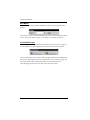
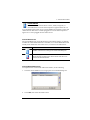
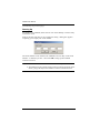
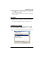
Exit Macro
The Exit Macro panel contains a dropdown listbox of user created System
macros:
You can select a macro from the list that will execute when exiting the remote
server. See System Macros, page 77, for details on creating exit macros.
Telnet/SSH Viewer
If Serial Console Management has been enabled (see Serial Console, page 51),
a Telnet/SSH Viewer panel displays directly below the Exit Macro panel:
These viewers allow users to open a Telnet or SSH session to the CN8000 from
the browser. Depending on the user’s permissions (see Permissions, page 50),
the Telnet Viewer link or SSH Viewer link, or both links are shown.
Click the appropriate link to have the viewer open the session.
24
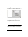
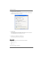
3. Browser Login
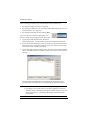
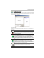
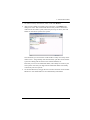
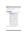
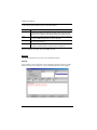
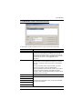
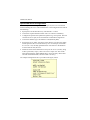
User Preferences
The User Preferences page allows the user to set three parameters: Viewer,
Language, and Password:
The page settings are explained in the following table:
Setting
Viewer
Function
You can choose which viewer is used when accessing a server:
Auto Detect will select the appropriate viewer based on the web
browser used; WinClient for Windows Internet Explorer; Java Client for
other web browsers (Firefox, etc.).
Java will open the Java based viewer regardless of the web browser
being used.
User Select lets IE users bypass the Auto Detect choice and choose
for themselves whether to use the WinClient or Java Applet Viewer.
After making your choice, click Apply.
Language
Selects the language that the interface displays in. Drop down the list to
make your selection.
Selecting Auto causes the CN8000 to display the pages in the same
language that the browser is set to.
Note: If your browser is set to a non-supported language, the CN8000
looks to what your server’s operating system is set to. If the operating
system is set to a supported language it will use that language to display
its pages. If the operating system is set to a non-supported language, the
CN8000 defaults to English.
After making your choice, click Apply.
Change
Password
To change your password, key the new password into the New Password
input box; key the exact same characters into the Confirm New Password
input box; then click Change Password to set the new password.
25
CN8000 User Manual
This Page Intentionally Left Blank
26
Chapter 4
Administration
Introduction
The administration utilities, represented by the icons located across the top of
the CN8000 web page, are used to configure the CN8000’s operating
environment.
This chapter discusses each of them in turn.
Note: 1. As you make your configuration changes in each dialog box, click
Apply to save them.
2. Some configuration changes only take effect after a CN8000 reset.
For those changes, a check is automatically put in the Reset on Exit
box (see Customization, page 58). To have the changes take effect,
log out and then log back in again.
3. If you don't have Configuration privileges (see User Management,
page 49), the Administration configuration dialogs are not available.
27
CN8000 User Manual
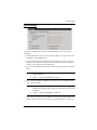
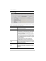
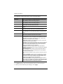
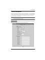
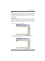
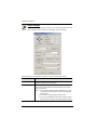
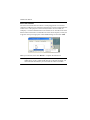
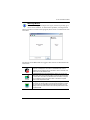
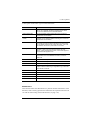
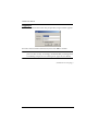
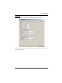
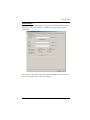
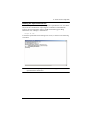
Device Information
The Device Information page is the first of the Administration pages, and
provides information about the CN8000's status.
An explanation of each of the fields is given in the table below:
Field
Explanation
Device Name:
To make it easier to manage installations that have more than one
CN8000, each one can be given a name. To assign a name for the
CN8000, key in one of your choosing here (16 characters max.),
then click Apply.
MAC Address:
The CN8000's MAC Address displays here.
Firmware Version:
Indicates the CN8000's current firmware version level. New
versions of the CN8000's firmware can be downloaded from our
website as they become available (see Firmware Upgrade,
page 62). You can reference this number to see if there are newer
versions available on the website.
IPV4 Address
Displays the CN8000’s Internet Protocol Version 4 (32 bit) address
(in the legacy format).
DNS
The IP address of the Domain Name Server.
IPV6 Address
Displays the CN8000’s Internet Protocol Version 6 (128 bit)
address (in the new format). See IPv6, page 165 for details.
28
4. Administration
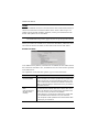
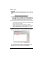
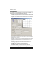
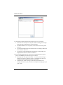
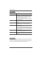
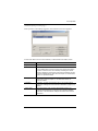
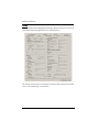
Network
The Network dialog is used to specify the CN8000's network environment.
Service Ports
If a firewall is being used, the Administrator can specify the port numbers that
the firewall will allow (and set the firewall accordingly). If a port other than the
default is set, users must specify the port number as part of the IP address when
they log in. If not, an invalid port number (or no port number) is specified, the
CN8000 will not be found.
(Continues on next page.)
29
CN8000 User Manual
(Continued from previous page.)
An explanation of the fields is given in the table below:
Field
HTTP
Explanation
The port number for a browser login. The default is 80.
HTTPS
The port number for a secure browser login. The default is 443.
Telnet Port
The port for Telnet access. The default is 23.
Program
This is the port number for connecting to the CN8000 from the
Windows Client and Java Applet Viewers, and from the Windows
and Java AP programs. The default is 9000.
Virtual Media
This is the port number used for data transfer using the CN8000’s
virtual media feature. Valid entries are from 1–65535. The default is
9003.
SSH Port
The port for SSH access. The default is 22.
Note: 1. Valid entries for all of the Service Ports are from 1–65535.
2. The service ports cannot have the same value. You must set a
different value for each one.
3. If there is no firewall (on an Intranet, for example), it doesn’t matter
what these numbers are set to, since they have no effect.
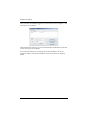
IP Address
The CN8000 can either have its IP address assigned dynamically at bootup
(DHCP), or it can be given a fixed IP address.
For dynamic IP address assignment, select the Obtain an IP address
automatically, radio button. (This is the default setting.)
To specify a fixed IP address, select the Set IP address manually, radio
button and fill in the IP address.
Note: 1. If you choose Obtain IP address automatically, when the switch starts
up it waits to get its IP address from the DHCP server. If it hasn’t
obtained the address after one minute, it automatically reverts to its
factory default IP address (192.168.0.60.)
2. If the CN8000 is on a network that uses DHCP to assign network
addresses, and you need to ascertain its IP address, see IP Address
Determination, page 163, for information.
30
4. Administration
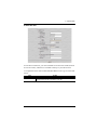
DNS Server
The CN8000 can either have its DNS server address assigned automatically, or
a fixed address can be specified.
For automatic DNS Server address assignment, select the Obtain DNS
server address automatically, radio button.
To specify a fixed address, select the Use the following DNS server
address, radio button and fill in the required information.
Note: Specifying at the alternate DNS Server address is optional.
Network Transfer Rate
This setting allows you to tailor the size of the data transfer stream to match
network traffic conditions by setting the rate at which the CN8000 transfers
data to remote computers. The range is from 4–99999 Kilobytes per second
(KBps).
Finishing Up
After making any network changes, be sure Reset on exit on the Customization
page (see Customization, page 58) has been enabled (there is a check in the
checkbox), before logging out. This allows network changes to take effect
without having to power the CN8000 off and on.
31
CN8000 User Manual
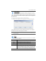
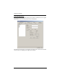
ANMS
The Advanced Network Management Settings page allows you to set up login
authentication and authorization management from external sources. It is
divided into several sections, each of which is described in the sections that
follow.
IP Installer
The IP Installer is an external Windows-based utility for assigning IP addresses
to the CN8000.
Click one of the radio buttons to select Enable, View Only, or Disable for the
IP Installer utility. See page 163for IP Installer details.
Note: 1. If you select View Only, you will be able to see the CN8000 in the IP
Installer’s Device List, but you will not be able to change the IP
address.
2. For security, we strongly recommend that you set this to View Only
or Disable after using it.
32
4. Administration
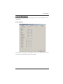
SMTP Settings
To have the CN8000 email reports from the SMTP server to you, do the
following:
1. Enable the Enable report from the following SMTP server, and key in the
IP address of your SMTP server.
2. If your server requires authentication, put a check in the Server requires
authentication checkbox, and key in the appropriate account information
in the Account Name and Password fields.
3. Key in the email address of where the report is being sent from in the From
field.
Note: 1. Only one email address is allowed in the From field, and it cannot
exceed 64 Bytes.
2. 1 Byte = 1 English alphanumeric character.
4. Key in the email address (addresses) of where you want the SMTP reports
sent to in the To field.
Note: 1. If you are sending the report to more than one email address,
separate the addresses with a semicolon. The total cannot exceed
256 Bytes.
2. 1 Byte = 1 English alphanumeric character.
5. Select the report options you would like sent. Choices include: Report IP
address, Report system reboot, Report user login and Report user logout.
33
CN8000 User Manual
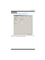
Log Server
Important transactions that occur on the CN8000, such as logins and internal
status messages, are kept in an automatically generated log file
Specify the MAC address of the computer that the Log Server runs on in
the MAC address field.
Specify the port used by the computer that the Log Server runs on to listen
for log details in the Port field. The valid port range is 1–65535. The
default port number is 9001.
Note: The port number must different than the one used for the Program
port (see Program, page 30).
See Chapter 8, The Log Server, for details on setting up the log server. The Log
File is discussed on page 111.
SNMP Server
To be notified of SNMP trap events, do the following:
1. Check Enable SNMP Agent.
2. Key in the IP address and the port number of the computer to be notified of
SNMP trap events. The valid port range is 1-65535.
Note: The following SNMP trap events are sent: System Power On, Login
Failure, and System Reset.
34
4. Administration
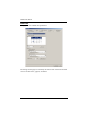
Syslog Server
To record all the events that take place on the CN8000 and write them to a
Syslog server, do the following:
1. Check Enable.
2. Key in the IP address and the port number of the Syslog server. The valid
port range is 1-65535.
DDNS
DDNS allows the mapping of a dynamic IP address assigned by a DHCP server
to a hostname. To provide DDNS capability for the CN8000, do the following:
1. Check Enable.
2. Enter the hostname that you registered with your DDNS service provider.
3. Drop down the list to select the DDNS service you are registered with.
4. Key in the Username and Password that authenticates you with your
DDNS service.
5. If the CN8000’s IP address changes, it must update the DDNS server so
that the new address is properly associated with its hostname. If it fails to
update the DDNS server, it must try again at a later time. Key in the
amount of time (in hours) to wait before trying to update the DHCP server
again.
35
CN8000 User Manual
Disable Local Authentication
Selecting this option will disable login authentication locally on the CN8000.
The switch can only be accessed using LDAP, LDAPS, MS Active Directory,
RADIUS or CC Management authentication.
RADIUS Settings
To allow authentication and authorization for the CN8000 through a RADIUS
server, do the following:
1. Check Enable.
2. Fill in the IP addresses and port numbers for the Preferred and Alternate
RADIUS servers.
3. In the Timeout field, set the time in seconds that the CN8000 waits for a
RADIUS server reply before it times out.
4. In the Retries field, set the number of allowed RADIUS retries.
5. In the Shared Secret field, key in the character string that you want to use
for authentication between the CN8000 and the RADIUS Server.
36
4. Administration
6. On the RADIUS server, set the access rights for each user according to the
information in the table, below:
Character
Meaning
c
Grants the user administrator privileges, allowing the user to configure
the system.
w
Allows the user to access the system via the Windows Client program.
j
Allows the user to access the system via the Java applet.
p
Allows the user to Power On/Off, Reset devices via an attached
PN0108.
l
Allows the user to access log information via the user's browser.
v
Limits the user's access to only viewing the video display.
s
Allows the user to use the Virtual Media function in Read Only mode.
m
Allows the user to use the Virtual Media function in Read/Write mode.
t
Allows the user to access the system via a Telnet session.
h
Allows the user to access the system via an SSH session.
a
Allows the user to access the system via a Telnet or SSH session
su/user
Where user represents the Username of a CN8000 user whose
permissions reflect the permissions you want the RADIUS authorized
user to have.
Note: 1. The characters are not case sensitive. Capitals or lower case work
equally well.
2. Characters are comma delimited.
RADIUS Examples
RADIUS Server access rights examples are given in the table, below:
String
c,w,p
w,j,l
Meaning
User has administrator privileges; user can access the system via the
Windows Client; user can access the attached PN0108
User can access the system via the Windows Client; user can access the
system via the Java Applet; user can access log information via the user's
browser.
37
CN8000 User Manual
LDAP Settings
To allow authentication and authorization for the CN8000 via LDAP / LDAPS,
refer to the information in the table, below:
Item
Action
Enable
Put a check in the Enable checkbox to allow LDAP / LDAPS
authentication and authorization.
LDAP / LDAPS
Click a radio button to specify whether to use LDAP or LDAPS.
Enable Authorization
Select whether to enable Enable Authorization, or not.
1. If enabled (the box is checked), the LDAP / LDAPS server
directly returns a ‘permission’ attribute and authorization for
the user that is logging in. With this selection the LDAP
schema must be extended. See LDAP Server Configuration, page 139, for details.
2. If not enabled (no check in the box), the result the server
returns indicates whether the user that is logging in belongs
to the ‘CN8000 Admin Group’. If the result is ‘yes’ the user
has full access rights; if the result is ‘no’, the user only has
limited access rights.
Note: Consult the LDAP / LDAPS administrator to
ascertain whether to enable the Enable Authorization
function, or not.
LDAP Server IP and
Port
Fill in the IP address and port number for the LDAP or LDAPS
server. For LDAP, the default port number is 389; for LDAPS,
the default port number is 636.
Timeout
Set the time in seconds that the CN8000 waits for an LDAP or
LDAPS server reply before it times out.
LDAP Administrator
DN
Consult the LDAP / LDAPS administrator to ascertain the
appropriate entry for this field. For example, the entry might
look like this:
cn=LDAPAdmin,ou=cn8000,dc=aten,dc=com
38
4. Administration
Item
Action
LDAP Administrator
Password
Key in the LDAP administrator’s password.
Search DN
Set the distinguished name of the search base. This is the
domain name where the search starts for user names.
Note: If Enable Authorization is not checked, this field must
include the entry where the CN8000 Admin Group is created.
Consult the LDAP / LDAPS administrator to ascertain the
appropriate value.
CN8000 Admin Group Key in the Group Name for CN8000 administrator users.
Note: If Enable Authorization is not checked, this field is used
to authorize users that are logging in. If a user is in this group,
the user receives full access rights. If a user is not in this
group, the user only receives limited access rights. Consult the
LDAP / LDAPS administrator to ascertain the appropriate
value.
CC Management Settings
To allow authorization for the CN8000 through a CC (Control Center) server,
check Enable and fill in the CC Server’s IP address and the port that it listens
on in the appropriate fields.
39
CN8000 User Manual
Security
The Security page controls access to the CN8000.
User Station Filters
If any filters have been configured, they appear in the IP Filter and/or MAC
Filter list boxes.
IP and MAC Filters control access to the CN8000 based on the IP and/or MAC
addresses of the computers attempting to connect. A maximum of 100 IP filters
and 100 MAC filters are allowed.
To enable IP and/or MAC filtering, Click to put a check mark in the IP Filter
Enable and/or MAC Filter Enable checkbox.
If the include button is checked, all the addresses within the filter range are
allowed access; all other addresses are denied access.
If the exclude button is checked, all the addresses within the filter range
are denied access; all other addresses are allowed access.
40
4. Administration
Adding Filters
To add an IP filter, do the following:
1. Click Add. A dialog box similar to the one below appears:
2. Key the address you want to filter in the From: field.
To filter a single IP address, key the same address in the To: field.
To filter a continuous range of addresses, key in the end number of the
range in the To: field.
3. After filling in the address, click OK.
4. Repeat these steps for any additional IP addresses you want to filter.
To add a MAC filter, do the following:
1. Click Add. A dialog box similar to the one below appears:
2. Specify the MAC address in the dialog box, then click OK.
3. Repeat these steps for any additional MAC addresses you want to filter.
IP Filter / MAC Filter Conflict
If there is a conflict between an IP filter and a MAC filter – for example, where
a computer’s IP address is allowed by the IP filter but it’s MAC address is
excluded by the MAC filter – then that computer’s access is blocked.
41
CN8000 User Manual
In other word’s, if either filter blocks a computer, then the computer is blocked,
no matter what the other filter is set to.
Modifying Filters
To modify a filter, select it in the IP Filter or MAC Filter list box and click
Modify. The Modify dialog box is similar to the Add dialog box. When it
comes up, simply delete the old address(es) and replace it with the new one(s).
Deleting Filters
To delete a filter, select it in the IP Filter or MAC Filter list box and click
Delete.
Login String
The Login String lets the Administrator specify a login string that users must
include (in addition to the IP address) when they access the CN8000 with a
browser. For example:
192.168.0.126/CN8000
The following characters are allowed:
0–9 a–z A–Z ~ ! @ $ ^ & * ( ) _ + ‘ - = [ ] { } ; ’ < > , . |
The following characters are not allowed:
% ” : / ? # \ [Space]
Compound characters (É Ç ñ ... etc.)
Note: 1. There must be a forward slash between the IP address and the string.
2. If no login string is specified here, anyone will be able to access the
CN8000 login page using the IP address alone. This makes your
installation less secure.
For security purposes, we recommend that you change this string occasionally.
42
4. Administration
Account Policy
In the Account Policy section, system administrators can set policies governing
usernames and passwords.
The meanings of the Account Policy entries are explained in the table below:
Entry
Explanation
Minimum Username Length
Sets the minimum number of characters required for
a username. Acceptable values are from 1–16. The
default is 6.
Minimum Password Length
Sets the minimum number of characters required for
a password. Acceptable values are from 0–16. A
setting of 0 means that no password is required.
Users can login with only a Username. The default is
6.
Password Must Contain At
Least
Checking any of these items requires users to
include at least one uppercase letter, one lowercase
letter or one number in their password.
Note: This policy does not affect existing user
accounts. Only new user accounts created after this
policy has been enabled, and users required to
change their passwords are affected.
Disable Duplicate Login
Check this to prevent users from logging in with the
same account at the same time.
43
CN8000 User Manual
Login Failures
For increased security, the Login Failures section allows administrators to set
policies governing what happens when a user fails to log in successfully.
To set the Login Failures policies, check the Enable checkbox (the default is
for Login Failures to be enabled). The meanings of the entries are explained in
the table below:
Entry
Explanation
Allowed
Sets the number of consecutive failed login attempts
that are permitted from a remote computer. The
default is 5 times.
Timeout
Sets the amount of time a remote computer must
wait before attempting to login again after it has
exceeded the number of allowed failures. The
default is 3 minutes.
Lock Client PC
If this is enabled, after the allowed number of failures
have been exceeded, the computer attempting to log
in is automatically locked out. No logins from that
computer will be accepted. The default is enabled.
Note: This function relates to the client computer’s
IP. If the IP is changed, the computer will no longer
be locked out.
Lock Account
If this is enabled, after the allowed number of failures
have been exceeded, the user attempting to log in is
automatically locked out. No logins from the
username and password that have failed will be
accepted. The default is enabled.
Note: If you don’t enable Login Failures, users can attempt to log in an
unlimited number of times with no restrictions. For security purposes,
we recommend that you enable this function and enable the lockout
policies.
44
4. Administration
Encryption
These flexible encryption alternatives for keyboard/mouse, video, and virtual
media data let you choose any combination of DES; 3DES; AES; RC4; or a
Random cycle of any or all of them.
Enabling encryption will affect system performance – no encryption offers the
best performance; the greater the encryption the greater the adverse effect. If
you enable encryption, the performance considerations (going from best to
worst) are as follows:
RC4 offers the least performance impact; DES is next; then 3DES or AES
The RC4 + DES combination offers the least impact of any combination
45
CN8000 User Manual
Virtual Media
The CN8000’s Virtual Media feature allows a drive, folder, image file,
removable disk, or smart card reader on a user’s system to appear and act as if
it were installed on the remote server.
Read Only refers to the redirected device being able to send data to the
remote server, but not to have data from the remote server written to it. If
Read Only is selected, even users with Read/Write permissions will only
be able to read – they will not be able to write.
Read/Write refers to the redirected device being able to send data to the
remote server, as well as being able to have data from the remote server
written to it.
The default is for Read Only. If you want the redirected device to be writable
as well as readable, click to put a check in the Enable Write checkbox.
Note: 1. This policy operates on the device level. If Read Only is selected, the
device will only be able to be read – regardless of a user’s Read/Write
user account permissions.
2. If Read/Write is selected, the ability of a user to write depends on the
user’s Read/Write user account permissions.
46
4. Administration
Private Certificate
When logging in over a secure (SSL) connection, a signed certificate is used to
verify that the user is logging in to the intended site. For enhanced security, the
Private Certificate section allows you to use your own private encryption key
and signed certificate, rather than the default ATEN certificate.
There are two methods for establishing your private certificate: generating a
self-signed certificate; and importing a third-party certificate authority (CA)
signed certificate.
Generating a Self-Signed Certificate
If you wish to create your own self-signed certificate, a free utility –
openssl.exe – is available for download over the web. See Self-Signed Private
Certificates, page 175 for details about using OpenSSL to generate your own
private key and SSL certificate.
Obtaining a CA Signed SSL Server Certificate
For the greatest security, we recommend using a third party certificate
authority (CA) signed certificate. To obtain a third party signed certificate, go
to a CA (Certificate Authority) website to apply for an SSL certificate. After
the CA sends you the certificate, save it to a convenient location on your
computer.
Importing the Private Certificate
To import the private certificate, do the following:
1. Click Browse to the right of Private Key; browse to where your private
encryption key file is located; and select it.
2. Click Browse to the right of Certificate; browse to where your certificate
file is located; and select it.
3. Click Upload to complete the procedure.
Note: Both the private encryption key and the signed certificate must be
imported at the same time.
47
CN8000 User Manual
Others
Browser Service allows the administrator to limit the scope of browser
access to the CN8000. Put a check in the checkbox to enable this function,
then select the browser limitation in the drop down list box. Choices are
explained in the following table:
Item
Explanation
Disable Browser
If this is selected, the CN8000 cannot be accessed via
a browser. It can only be accessed from the AP
programs (see AP Operation, page 121).
Disable HTTP
If this is selected, the CN8000 can be accessed via a
browser, but not from an ordinary (HTTP) login
connection – it can only be accessed over a secure
HTTPS (SSL) connection.
Disable HTTPS (SSL)
If this is selected, the CN8000 can be accessed via a
browser over an ordinary (HTTP) login connection, but
not via a secure HTTPS (SSL) connection.
If Disable Authentication is checked, no authentication procedures are
used to check users attempting to log in. Users gain Administrator access
to the CN8000 simply by entering the correct IP address in their browser.
Note: Enabling this setting creates an extremely dangerous result as far as
security goes, and should only be used under very special
circumstances.
48
4. Administration
User Management
The User Management page is used to create and manage user profiles. Up to
64 user profiles can be established.
To add a user profile, fill in the information asked for in the right panel,
then click Add. The new user’s name appears in the left panel.
To delete a user profile, select it from the names displayed in the left panel,
and click Remove. The user’s name is removed from the panel.
To modify a user profile, first select it from the list in the left panel; change
the information that appears in the right panel; then click Update.
Note: The user’s password is not displayed – the Password and Confirm
password fields are filled with round bullets. If you do not want to
change the user’s password, simply leave the two fields as is. If you
do want to change the user’s password, key the new password in the
Password and Confirm password fields.
The Admin and User radio buttons select automatically configured
permissions. If you wish to modify these permissions, choose the Select
radio button, then specify the permissions individually.
49
CN8000 User Manual
An explanation of the profile items is given in the table below:
Item
Explanation
Username
From 1 to16 characters are allowed depending on the Account
Policy settings. See Account Policy, page 43.
Password
From 0 to16 characters are allowed depending on the Account
Policy settings. See Account Policy, page 43.
Confirm Password
To be sure there is no mistake in the password you are asked to
enter it again. The two entries must match.
Description
Additional information about the user that you may wish to
include.
Admin
Gives the user Administrator level access to the CN8000. All
permissions (except View Only) are granted (see below).
User
Gives the user User level access to the CN8000. Windows Client,
Power Manager, and Java Client permissions are granted (see
below).
Select
Select is the default account type. It allows the administrator to
select which permissions the user will be allowed.
Permissions
Click to place/remove a check mark next to an item to
grant/withhold access to that aspect of the CN8000’s operation.
Win Client: Checking Win Client allows a user to access the
CN8000 via the Windows Client software.
Java Client: Checking Java Client allows a user to access the
CN8000 via the Java Client software.
View Only: Checking View Only allows a user to view the video of
the display of the computers attached to the ports of the KVM
switch connected to the CN8000, but they are not allowed to
perform any operations on the computers.
Configure: Checking Configure gives a user Administrator
privileges, and allows the user to set up and modify the CN8000's
operating environment.
Power Management: Checking Power Management allows a
user to Power On / Power Off / Reset devices via an attached
Power Over the NET™ unit.
Log: Checking Log allows a user to view the contents of the log
file.
Enable Telnet/SSH: If Serial Console management is enabled
(see Console Management, page 51), checking Enable Telnet/
SSH allows a user to open a Telnet and/or SSH session. Drop
down the list to select the type of login allowed.
Enable Virtual Media: Checking Enable Virtual Media allows a
user to utilize the CN8000’s Virtual Media capabilities (see Virtual
Media, page 85 for details). Drop down the list to select whether
the user has Read/Write, or Read Only permission.
The Reset button clears all the information shown in the right panel.
When you have made all your changes, click Apply.
50
4. Administration
Console Management
The Console Management page consists of two sub-pages – Serial Console and
OOBC – that are used to set up the operating parameters for the CN8000's RS232 (serial) port. An explanation of the parameters and how to set them are
given in the sections that follow.
Note: Only one of these functions can be active at a time. Selecting one
automatically disables the other.
Serial Console
When the Serial Console radio button (at the top of the page), is selected, the
screen looks similar to the one in the screenshot below:
51
CN8000 User Manual
To set up the serial communications parameters, put a check in the Enable
checkbox, and make your parameter selections according to the information
provided in the table below.
Port Property Settings
The meanings of the property settings are given in the following table:
Setting
Meaning
Baud Rate
This sets the port’s data transfer speed. Choices are from 300—
115200 (drop down the list to see them all). Set this to match the
baud rate setting of the connected device. Default is 9600 (which
is a basic setting for many serial devices).
Data Bits
This sets the number of bits used to transmit one character of
data. Choices are: 5, 6, 7 and 8. Set this to match the data bit
setting of the connected device. Default is 8 (which is the default
for the majority of serial devices).
Parity
This bit checks the integrity of the transmitted data. Choices are:
None; Odd; Even; Mark; Space. Set this to match the parity setting
of the connected device. Default is None (which is the default for
the majority of serial devices).
Stop Bits
This indicates that a character has been transmitted. Set this to
match the stop bit setting of the connected device. Choices are: 1
and 2. Default is 1 (which is the default for the majority of serial
devices).
Flow Control
This allows you to choose how the data flow will be controlled.
Choices are: None, Hardware (RTS/CTS), and XON/XOFF. Set
this to match the flow control setting of the connected device.
Default is None.
Enable Toggle
DTR
Enabling this parameter allows the DTR signal to toggle between
disabled and enabled when the port is occupied. Choices are: No
and Yes. Default is No.
Note: For some devices, in order for Enabled to work correctly,
you must first disable DTR (select No, then click Update), then
Enable it (select Yes, then click Update).
Online Detect
This allows you to set the DSR signal to detect online status or not.
Choices are: None and DSR. Default is DSR.
Out CRLF
Translation
This allows you to select whether to send a Carriage Return and
Line Feed signal (CRLF), or only a Carriage Return signal (CR).
Choices are: None (which sends CRLF) and CRLF → CR (which
only sends CR), Default is None.
Note: If your device outputs double spaced lines, it means that a
line feed is automatically added to a carriage return signal. In that
case, choose CRLF → CR.
Suspend
Character
The Suspend character is used to bring up the Suspend Menu in
Telnet sessions (see Permissions, page 50).
Note: Valid characters are from A–Z, except H, I, J, and M. Those
four characters may not be used.
52
4. Administration
Port Alert Settings
The Port Alert Settings dialog box provides a way for you to be informed about
events that occur on the devices connected to the CN8000's ports.
You can specify up to 10 types of events (e.g., Power On) in the Alert String
fields. When a specified alert occurs during the serial console session, the
CN8000 writes the event information to the log file.
53
CN8000 User Manual
OOBC
In case the CN8000 cannot be accessed with the usual LAN-based methods, it
can be accessed with an external modem via the switch’s RS-232 port. To
enable support for PPP (modem) operation, click to put a checkmark in the
Enable Out of Band Access checkbox.
Note: Enabling out of band access automatically enables Dial In operation.
See PPP Modem Operation, page 169, for set up and operation details.
When you enable out of band access, the Enable Dial Back, and Enable Dial
Out functions become available, as described in the sections that follow.
Enable Dial Back
As an added security feature, if this function is enabled, the switch disconnects
the connections that dial in to it, and dials back to one of the entries specified
in the table below.
An explanation of the dial back options is given in the table below:
Item
Enable Fixed
Number DialBack
Action
If this radio button is selected, the switch will dial back to the
modem whose phone number is specified here to initiate a PPP
session with the user. For the Phone Number field, key in the
phone number that the user wants the CN8000 to call back to.
Note: You need to specify a number here even if you intend to
use flexible dial back.
Enable Flexible Dial
Back
(Use username as
dial back phone
number)
For flexibility and convenience, if this radio button is selected
the modem that the CN8000 dials back to doesn’t have to be
fixed. It can dial back to any modem that is convenient for the
user. To do so, when you dial in to the CN8000:
When logging in, use the phone number of the modem that
you want the switch to dial back to for your Username.
Use the phone number specified in the Phone Number field
(above) for your Password.
54
4. Administration
Enable Dial Out
For the dial out function, you must establish an account with an ISP (Internet
Service Provider), and then use a modem to dial up to your ISP account.
An explanation of the items in the Enable Dial Back section is given in the table
below:
Item
ISP Settings
Action
Specify the telephone number, account name (username), and
password that you use to connect to your ISP.
55
CN8000 User Manual
Item
Action
Dial Out Schedule This entry sets up the times you want the CN8000 to dial out over
the ISP connection.
Every provides a listing of fixed times from every hour to every
four hours.
If you select Every two hours (for example), the CN8000 will
start dialing out every two hours beginning at the next
complete hour (if it is now 13:10, it will start dialling at 14:00).
If you don't want the CN8000 to dial out on a fixed schedule,
select Never from the list.
Daily at a specified time. Use the hh:mm format separated by a
semicolon (there is no space before or after the semicolon). For
example: 09:18
The CN8000 will dial out every day at the time(s) you specify.
PPP online time specifies how long you want the ISP connection
to last before terminating the session and hanging up the
modem. A setting of zero means it is always on line.
Emergency Dial
Out
If the CN8000 gets disconnected from the network, or the network
goes down, this function puts the CN8000 on line via the ISP dial up
connection.
If you choose PPP stays online until network recovery, the PPP
connection to the ISP will last until the network comes back up or
the CN8000 reconnects to it.
If you choose PPP online time the connection to the ISP will
terminate after the amount of time that you specify is up. A
setting of zero means it is always on line.
Dial Out Mail
Configuration
This section provides email notification of problems that occur on
the devices connected to the CN8000's ports (see SMTP Settings,
page 33).
Note: This email notification differs from the one configured under
SMTP Settings, page 33, in that it uses the ISP mail server rather
than the internal company’s mail server.
Key in the IP address or domain name of your SMTP server in
the SMTP Server IP Address field.
Key in the email address of the person responsible for the SMTP
server (or some other equally responsible administrator), in the
Email From field.
Key in the email address (addresses) of where you want the
report sent to in the To field. If you are sending the report to more
than one email address, separate the addresses with a comma
or a semicolon.
If your server requires authentication, put a check in the My
server requires authentication checkbox, then key in the
appropriate account name and password in the fields, below.
When you have finished making your settings on this page, click Apply.
56
4. Administration
Sessions
The Session page lets the administrator see at a glance all the users currently
logged into the CN8000, and provides information about each of their sessions.
The meanings of the headings at the top of the page are fairly straightforward.
The Client IP heading refers to the IP address that the user has logged in
from.
The Service heading refers to the means the user employed to connect to
the CN8000 (Browser, WinClient AP, JavaClient AP, etc.).
The Category heading lists the type of user who has logged in: Admin
(Administrator), User, or Select. (See User Management, page 49 for
details about user types.)
This page also gives the administrator the option of forcing a user logout by
selecting the user and clicking End Session.
57
CN8000 User Manual
Customization
The Customization page allows the Administrator to set Timeout, Login
failure, and Working mode parameters.
An explanation of the Customization parameters is given in the table below:
Parameter
Timeout
Working
Mode
58
Explanation
If there is no user input for the amount of time specified
here, the user is automatically logged out, and must log in
again before the CN8000 can be accessed. The default is
3 minutes.
Enable
ICMP
If ICMP is enabled, the CN8000 can be pinged. If it is not
enabled, the device cannot be pinged. The default is
Enabled.
Enable
device list
If this item is enabled, the device will show up in the list of
local CN8000 units on the AP Client Connection screen
(see The Windows Client Connection Screen, page 123).
If it is not enabled, it will not show up. The default is
Enabled,
Enable
multiuser
Enabling Multiuser operation permits more than one user
to log into the CN8000 at the same time. The default is
Enabled,
Force All to
Grayscale
If Force All to Grayscale is enabled, the remote display for
all users is changed to grayscale. This can speed up I/O
transfer in low bandwidth situations. The default is
Disabled,
4. Administration
Parameter
USB IO
Settings
Explanation
OS
Specifies the operating system that the server on the
connected port is using. Choices are Win, Mac, Sun, and
Other. The default is Win.
Language
Specifies the OS language being used by the server on
the connected port. Drop down the list to see the available
choices. The default is English US.
Multiuser Mode
Defines how a port is to be accessed when multiple users
have logged on, as follows:
Exclusive: The first user to switch to the port has
exclusive control over the port. No other users can view
the port.
Occupy: The first user to switch to the port has control
over the port. However, additional users may view the
port’s video display.
Share: Users simultaneously share control over the port.
Input from the users is placed in a queue and executed
chronologically. Under these circumstances, users can
take advantage of the Message Board, which allows a
user to take control of the keyboard and mouse or
keyboard, mouse, and video of a Share port (see The
Message Board, page 83).
Reset
Some configuration changes only take effect after a
CN8000 reset. These include changes on the Network
page; a Log Server port change; enabling/disabling
browser access; and upgrading the firmware.
For those changes, a check is automatically put in the
Reset on Exit box.
To have the changes take effect, log out and then log back
in again. A wait of approximately 30 to 60 seconds is
necessary before logging in following the reset.
Note:
If the CN8000’s performance degrades, reset it by putting
a check in the Reset on Exit box, and then log out / log in.
59
CN8000 User Manual
Date/Time
The Date/Time dialog page sets the CN8000 time parameters:
Set the parameters according to the information below.
Time Zone
To establish the time zone that the CN8000 is located in, drop down the
Time Zone list and choose the city that most closely corresponds to where
it is at.
If your country or region employs Daylight Saving Time (Summer Time),
check the corresponding checkbox.
60
4. Administration
Date
Select the month from the dropdown listbox.
Click < or > to move backward or forward by one year increments.
In the calendar, click on the day.
To set the time, key in the numbers using the 24 hour HH:MM:SS format.
Click Set to save your settings.
Network Time
To have the time automatically synchronized to a network time server, do the
following:
1. Check the Enable auto adjustment checkbox.
2. Drop down the time server list to select your preferred time server
– or –
Check the Preferred custom server IP checkbox, and key in the IP address
of the time server of your choice.
3. If you want to configure an alternate time server, check the Alternate time
server checkbox, and repeat step 2 for the alternate time server entries.
4. Key in your choice for the number of days between synchronization
procedures.
5. If you want to synchronize immediately, click Adjust Time Now.
Note: After checking the Enable auto adjustment checkbox, you must click
Adjust Time Now or Set to save the change. Otherwise, the setting will
be lost.
61
CN8000 User Manual
Maintenance
The Maintenance page allows the Administrator to upgrade the CN8000’s
firmware, and to backup and restore the CN8000’s configuration settings and
user profile information.
Firmware Upgrade
As new versions of the CN8000 firmware become available, they can be
downloaded from our website. Check the website regularly to find the latest
information and packages.
To upgrade the firmware, do the following:
1. Download the new firmware file to your computer.
2. Open your browser; log in to the CN8000; and click the Firmware icon to
bring up the Firmware File dialog box:
3. Click Browse; navigate to the directory that the new firmware file is in
and select the file.
4. Click Upgrade Firmware.
If Check Firmware Version is enabled (the default), when you perform an
upgrade the current firmware level is compared with that of the upgrade
file. If the current version is higher than the upgrade version, a message
appears informing you of the fact and the procedure stops.
Note: If you want to install an older firmware version, you must uncheck
the Check Firmware Version checkbox before clicking Upgrade
Firmware.
5. After the upload completes, a message appears on the screen to inform you
that the operations succeeded. Click Logout at the bottom left of the Main
web page.
6. In the screen that comes up click Yes to confirm that you want to exit and
reset the CN8000.
Note: You will need to wait a bit before logging back in.
62
4. Administration
Backup
The Backup section of the page gives you the ability to back up the CN8000’s
configuration and user profile information.
To perform a backup, do the following:
1. (Optional) In the Password field, key in a password for the file.
Note: If you set a password, make a note of it, since you will need it to be
able to perform restore operations with the file.
2. Click Backup.
3. When the browser asks what you want to do with the file, select Save to
disk; then save it in a convenient location.
Note: The CN8000 saves all its backup files as CN8000BKUP.conf. If you
want to save more than one backup file, simply rename the file to
something convenient when you save it.
63
CN8000 User Manual
Restore
Backed up User Account and Configuration information can be restored with
the Restore section of the page. Information currently configured on the
CN8000 will be replaced with the information that you restore.
To restore a previous backup, do the following:
1. If a password was set when the backup was made, key the same password
that you used to save the backup file in the Password field. If a password
wasn’t set, you can leave this field blank.‘
2. Click Browse; navigate to the file and select it.
Note: If you renamed the file, you can leave the new name. There is no
need to return it to its original name.
3. Select which parts of the backup you wish to restore:
Select the All radio button to restore both User Account and all
Configuration information
Select the User Account radio button to only restore User Account
information
Select the User Select radio button to choose which parts of the backed
up information you wish to restore, then click the checkboxes to
select/deselect the restore elements.
4. When you have made your selections, click Restore.
After the file is restored, a message appears to inform you that the
procedure succeeded.
64
Chapter 5
The WinClient Viewer
Starting Up
The WinClient Viewer is only available when you log in using the Microsoft
Internet Explorer (IE) browser. After you log in (see Logging In, page 19),
click the Open Windows Client link on the Remote Console Preview panel.
Note: The links that appear below the Refresh button depend on the browser
you are using, and your User Preferences Viewer choice. See Remote
Console Preview, page 23, for details
65
CN8000 User Manual
A second or two after you click the Open Windows Client link, the remote
server’s display appears as a window on your desktop:
Navigation
You can work on the remote system via the screen display on your monitor just
as if it were your local system.
You can maximize the window, drag the borders to resize the window; or
use the scrollbars to move around the screen.
You can switch between your local and remote programs with [Alt + Tab].
Note: 1. Due to net lag, there might be a slight delay before your keystrokes
show up. You may also have to wait a bit for the remote mouse to
catch up to your local mouse before you click.
2. Due to net lag, or insufficient computing power on the local machine,
some images, especially motion images, may display poorly.
66
5. The WinClient Viewer
The WinClient Control Panel
The WinClient control panel is hidden at the upper or lower center of the screen
(the default is up). It becomes visible when you move the mouse pointer over it:
Note: 1. The above image shows the complete Control Panel. The icons that
appear can be customized. See Control Panel Configuration,
page 94, for details.
2. To move the Control Panel to a different location on the screen, place
the mouse pointer over the text bar area, then click and drag.
By default, the left of the top text row shows the video resolution of the
remote display. As the mouse pointer moves over the icons in the icon bar,
however, the information in the top text row changes to describe the icon's
function. In addition, if a message from another user is entered in the
message board, and you have not opened the message board in your
session, the message will appear in the top row.
If the User Info function has been enabled under Control Panel
Configuration (see User Info, page 95), the total number of users currently
logged into the CN8000 displays in the center of the upper text row.
Right clicking in the text row area brings up a menu that allows you to
select options for the Screen Mode, Zoom, Mouse Pointer type, Mouse
Sync Mode and Macro List. These functions are discussed in the sections
that follow.
67
CN8000 User Manual
Control Panel Functions
The Control Panel functions are described in the table below.
Note: Clicking the T button at the top right of the dialog boxes that appear for
the control panel functions brings up a slider to adjust the transparency
of the dialog box. After making your adjustment, click anywhere in the
dialog box to dismiss the slider.
Icon
Function
This is a toggle. Click to make the Control Panel persistent – i.e., it
always displays on top of other screen elements. Click again to
have it display normally.
Click to bring up the Macros dialog box (see page 71 for details).
Click to bring up the Video Options dialog box. Right-click to perform
a quick Auto Sync (see Video Settings, page 80, for details).
Video Settings
Click to perform a video and mouse autosync operation. It is the
same as clicking the Auto-sync button in the Video Options dialog
box (see Video Settings, page 80).
Video Autosync
Toggles the display between Full Screen Mode and Windowed
Mode.
Click to take a snapshot (screen capture) of the remote display.
See Snapshot, page 95, for details on configuring the Snapshot
parameters.
Click to bring up the Message Board (see The Message Board,
page 83).
Click to send a Ctrl+Alt+Del signal to the remote system.
Click to toggle the remote display between color and grayscale.
68
5. The WinClient Viewer
Icon
Function
Click to bring up the Virtual Media dialog box. The icon changes
when a virtual media device is started on the port. See Virtual
Media, page 85, for specific details.
Note: This icon displays in gray when the function is disabled or not
available to the user.
Click to zoom the remote display window.
Note: This feature is only available in windowed mode (Full Screen
Mode is off). See Zoom, page 89, for details.
Click to bring up the on-screen keyboard (see The On-Screen
Keyboard, page 90).
Click to select the mouse pointer type.
Note: This icon changes depending on which mouse pointer type is
selected (see Mouse Pointer Type, page 92).
Mouse Pointer
Click to toggle Automatic or Manual mouse sync.
When the selection is Automatic, a green √ appears on the icon.
When the selection is Manual, a red X appears on the icon.
See Mouse DynaSync Mode, page 92 for a complete explanation of
this feature.
Macro List
Click to display a dropdown Macro List of User macros. Access and
run macros more conveniently rather than using the Macros dialog
box (see the Macros icon in the table above, and the Macros section
on page 71).
Click to bring up the Control Panel Configuration dialog box.
See Control Panel Configuration, page 94, for details on configuring
the Control Panel.
Click to exit the remote view and go back to the web browser Main
Page.
Exit
69
CN8000 User Manual
Icon
Function
These icons show the Num Lock, Caps Lock, and Scroll Lock status
of the remote computer.
When the lock state is On, the LED is bright green and the lock
hasp is closed.
When the lock state is Off, the LED is dull green and the lock
hasp is open.
Click on the icon to toggle the status.
Note: These icons and your local keyboard icons are in sync.
Clicking an icon causes the corresponding LED on your keyboard to
change accordingly. Likewise, pressing a Lock key on your
keyboard causes the icon’s color to change accordingly.
Click to display information about the Windows Client version.
70
5. The WinClient Viewer
Macros
The Macros icon provides access to three functions found in the
Macros dialog box: Hotkeys, User Macros, and System Macros. Each
of these functions is described in the following sections.
Hotkeys
Various actions, corresponding to clicking the Control Panel icons, can be
accomplished directly from the keyboard with hotkeys. Selecting the Hotkeys
radio button lets you configure which hotkeys perform the actions. The actions
are listed to the left; their hotkeys are shown to the right. Use the checkbox to
the left of an action’s name to enable or disable its hotkey.
If you find the default Hotkey combinations inconvenient, you can reconfigure
them as follows:
1. Highlight an Action, then click Set Hotkey.
2. Press your selected Function keys (one at a time). The key names appear in
the Hotkeys field as you press them.
You can use the same function keys for more than one action, as long
as the key sequence is not the same.
To cancel setting a hotkey value, click Cancel; to clear an action’s
Hotkeys field, click Clear.
3. When you have finished keying in your sequence, click Save.
To reset all the hotkeys to their default values, click Reset.
71
CN8000 User Manual
An explanation of the Hotkey actions is given in the table below:
Action
Explanation
Exit remote location Exits the remote view and goes back to the web browser Main
Page. This is equivalent to clicking the Exit icon on the Control
Panel. The default keys are F2, F3, F4.
Adjust Video
Brings up the Video Settings dialog box. This is equivalent to
clicking the Video Settings icon on the Control Panel. The default
keys are F5, F6, F7.
Toggle OSD
Toggles the Control Panel Off and On. The default keys are F3,
F4, F5.
Toggle mouse
display
If you find the display of the two mouse pointers (local and
remote) to be confusing or annoying, you can use this function to
shrink the non-functioning pointer down to a barely noticeable tiny
circle, which can be ignored. Since this function is a toggle, use
the hotkeys again to bring the mouse display back to its original
configuration. This is equivalent to selecting the Dot pointer type
from the Mouse Pointer icon on the Control Panel. The default
keys are F7, F8, F9.
Adjust mouse
This synchronizes the local and remote mouse movements. The
default keys are F7, F8, F9.
Video Auto-sync
This combination performs an auto-sync operation. It is
equivalent to clicking the Video Autosync icon on the Control
Panel. The default keys are F6, F7, F8.
Show/Hide Local
Cursor
Toggles the display of your local mouse pointer off and on. This is
equivalent to selecting the Null pointer type from the Mouse
Pointer icon on the Control Panel. The default keys are F4,F5.
Substitute Ctrl key
If your local computer captures Ctrl key combinations, preventing
them from being sent to the remote system, you can implement
their effects on the remote system by specifying a function key to
substitute for the Ctrl key. If you substitute the F11 key, for
example, pressing [F11 + 5] would appear to the remote system
as [Ctrl + 5]. The default key is F11.
Substitute Alt key
Although all other keyboard input is captured and sent to the
remote system, [Alt + Tab] and [Ctrl + Alt + Del] work on your local
computer. In order to implement their effects on the remote
system, another key may be substituted for the Alt key. If you
substitute the F12 key, for example, you would use [F12 + Tab]
and [Ctrl + F12 + Del]. The default key is F11.
Note: The Java Control Panel does not have this feature.
72
5. The WinClient Viewer
User Macros
User Macros are used to perform specific actions on the remote server. To
create the macro, do the following:
1. Select the User Macros radio button, then click Add.
2. In the dialog box that comes up, replace the “New Macro” text with a
name of your choice for the macro:
73
CN8000 User Manual
3. Click Record.
The dialog box disappears, and a small panel appears at the top left of the
screen:
4. Press the keys for the macro.
To pause macro recording, click Pause. To resume, click Pause again.
Clicking Show brings up a dialog box that lists each keystroke that you
make, together with the amount of time each one takes:
Clicking Cancel cancels all keystrokes.
When you have finished, click Stop. This is the equivalent of clicking
Done in Step 5.
Note: 1. Case is not considered – typing A or a has the same effect.
2. When recording the macro the focus must be on the remote screen. It
cannot be in the macro dialog box.
3. Only the default keyboard characters may be used. Alternate
characters cannot be used. For example, if the keyboard is Traditional
Chinese and default character is A the alternate Chinese character
obtained via keyboard switching is not recorded.
74
5. The WinClient Viewer
5. If you haven’t brought up the Show dialog, click Done when you have
finished recording your macro. You return to the Macros dialog box with
your system macro key presses displayed in the Macro column:
6. If you want to change any of the keystrokes, select the macro and click
Edit. This brings up a dialog box similar to the one for Show. You can
change the content of your keystrokes, change their order, etc.
7. Repeat the procedure for any other macros you wish to create.
75
CN8000 User Manual
After creating your macros, you can run them in any of three ways:
1. By using the hotkey (if one was assigned).
2. By opening the Macro List on the Control Panel and clicking the one you
want (see Macro List, page 69).
3. By opening this dialog box and clicking Play.
If you run the macro from this dialog box, you
have the option of specifying how the macro runs.
If you choose Play Without Wait, the macro
runs the keypresses one after another with no time delay between them.
If you choose Play With Time Control, the macro waits for the amount of
time between key presses that you took when you created it. Click on the
arrow next to Play to make your choice.
If you click Play without opening the list, the macro runs with the default
choice. The default choice (NoWait or TimeCtrl), is shown in the Playback
column.
You can change the default choice by clicking on the current choice
(NoWait in the screenshot above), and selecting the alternative choice.
Note: 1. Information about the Search function is given on page 77.
2. User Macros are stored on the Local Client computer of each user.
Therefore there is no limitation on the of number of macros, the size
of the macro names, or makeup of the hotkey combinations that
invoke them
76
5. The WinClient Viewer
Search
Search, at the bottom of the dialog box, lets you filter the list of macros that
appear in the large upper panel for you to play or edit. Click a radio button to
choose whether you want to search by name or by key; key in a string for the
search; then click Search. All instances that match your search string appear in
the upper panel.
System Macros
System Macros are used to create exit macros for when you close a session. For
example, as an added measure of security, you could create a macro that sends
the Winkey-L combination which would cause the remote device’s log in page
to come up the next time the device was accessed. To create the macro, do the
following:
1. Select System Macros, then click Add.
2. In the dialog box that comes up, replace the “New Macro” text with a
name of your choice for the macro:
77
CN8000 User Manual
3. Click Record.
The dialog box disappears, and a small panel appears at the top left of the
screen:
4. Press the keys for the macro.
To pause macro recording, click Pause. To resume, click Pause again.
Clicking Show brings up a dialog box that lists each keystroke that you
make, together with the amount of time each one takes (see page 78).
Note: 1. Case is not considered – typing A or a has the same effect.
2. When recording the macro the focus must be on the remote screen. It
cannot be in the macro dialog box.
3. Only the default keyboard characters may be used. Alternate
characters cannot be used. For example, if the keyboard is Traditional
Chinese and default character is A the alternate Chinese character
obtained via keyboard switching is not recorded.
5. If you haven’t brought up the Show dialog, click Done when you have
finished recording your macro. You return to the Macros dialog box with
your system macro key presses displayed in the Macro column:
6. If you want to change any of the keystrokes, select the macro and click
Edit. This brings up a dialog box similar to the one for Show. You can
change the content of your keystrokes, change their order, etc.
78
5. The WinClient Viewer
7. Repeat the procedure for any other macros you wish to create.
Once the system macros have been created, you can choose to run any one
them upon logging out of the CN8000 (see Exit Macro, page 24, for details).
Note: 1. Information about the Search function is given on page 77.
2. Systems macros are stored on the CN8000, therefore macro names
may not exceed 64 Bytes (1 Byte = 1 English alphanumeric
character), and hotkey combinations may not exceed 256 Bytes (each
key usually takes 3–5 Bytes).
79
CN8000 User Manual
Video Settings
The Video Settings dialog box allows you to adjust the placement and
picture quality of the remote screen display on your monitor.
The meanings of the adjustment options are given in the table below:
Option
Usage
Screen Position
Adjust the horizontal and vertical position of the remote computer
window by Clicking the Arrow buttons.
Auto-Sync
Click Auto-Sync to have the vertical and horizontal offset values
of the remote screen detected and automatically synchronized
with the local screen.
Note: 1. If the local and remote mouse pointers are out of sync,
in most cases, performing this function will bring them
back into sync.
2. This function works best with a bright screen.
3. If you are not satisfied with the results, use the Screen
Position arrows to position the remote display manually.
80
5. The WinClient Viewer
Option
RGB
Usage
Drag the slider bars to adjust the RGB (Red, Green, Blue)
values. When an RGB value is increased, the RGB component of
the image is correspondingly increased.
If you enable Set to Grayscale, the remote video display is
changed to grayscale.
Gamma
This section allows you to adjust the video display's gamma
level. This function is discussed in detail in the next section,
Gamma Adjustment.
Network Type
Select the type of internet connection that exists between the
Local Client computer and the CN8000. The CN8000 will use that
selection to automatically adjust the Video Quality and Detect
Tolerance settings to optimize the quality of the video display.
Since network conditions vary, if none of the pre-set choices
seem to work well, you can select Customize and use the Video
Quality and Detect Tolerance slider bars to adjust the settings to
suit your conditions.
Video Quality
Drag the slider bar to adjust the overall Video Quality. The larger
the value, the clearer the picture and the more video data goes
through the network. Depending on the network bandwidth, a
high value may adversely effect response time.
Enable Refresh
The CN8000 can redraw the screen every 1 to 99 seconds,
eliminating unwanted artifacts from the screen. Select Enable
Refresh and enter a number from 1 through 99. The CN8000 will
redraw the screen at the interval you specify. This feature is
disabled by default. Click to put a check mark in the box next to
Enable Refresh to enable this feature.
Note: 1. The switch starts counting the time interval when
mouse movement stops.
2. Enabling this feature increases the volume of video
data transmitted over the network. The lower the
number specified, the more often the video data is
transmitted. Setting too low a value may adversely
affect overall operating responsiveness.
Color Depth Control This setting determines the richness of the video display by
adjusting the amount of color information.
Detect Tolerance
This setting also relates to video quality. It governs detecting or
ignoring pixel changes. A high setting can result in a lower quality
display due to less data transfer. A lower setting will result in
better video quality, but setting the threshold too low may allow
too much data to be transferred, negatively impacting network
performance.
81
CN8000 User Manual
Gamma Adjustment
If it is necessary to correct the gamma level for the remote video display, use
the Gamma function of the Video Adjustment dialog box.
Under Basic configuration, there are ten preset and four user-defined levels
to choose from. Drop down the list box and choose the most suitable one.
For greater control, clicking the Advanced button brings up the following
dialog box:
Click and drag the diagonal line at as many points as you wish to achieve
the display output you desire.
Click Save As to save up to four user-defined configurations derived from
this method. Saved configurations can be recalled from the list box at a
future time.
Click Reset to abandon any changes and return the gamma line to its
original diagonal position.
Click OK to save your changes and close the dialog box.
Click Cancel to abandon your changes and close the dialog box.
Note: For best results, change the gamma while viewing a remote computer.
82
5. The WinClient Viewer
The Message Board
To alleviate the possibility of access conflicts resulting from multiple
user logins, the CN8000 provides a message board that allows users to
communicate with each other:
The Button Bar
The buttons on the Button Bar are toggles. Their actions are described in the
table below:
Button
Action
Enable/Disable Chat. When disabled, messages posted to the board
are not displayed. The button is shadowed when Chat is disabled. The
icon displays next to the user's name in the User List panel when the
user has disabled Chat.
Occupy/Release Keyboard/Video/Mouse. When a port is set to Occupy
mode (see Multiuser Mode, page 59), you can use this button to occupy
the KVM. When you Occupy the KVM, other users cannot see the video,
and cannot input keyboard or mouse data. The button is shadowed
when the KVM is occupied. The icon displays next to the user's name in
the User List panel when the user has occupied the KVM.
Occupy/Release Keyboard/Mouse. When a port is set to Occupy mode
(see Multiuser Mode, page 59), you can use this button to occupy the
KM. When you Occupy the KM, other users can see the video, but
cannot input keyboard or mouse data. The button is shadowed when the
KM is occupied. The icon displays next to the user's name in the User
List panel when the user has occupied the KM.
Show/Hide User List. When you Hide the User List, the User List panel
closes. The button is shadowed when the User List is open.
83
CN8000 User Manual
Message Display Panel
Messages that users post to the board - as well as system messages - display in
this panel. If you disable Chat, however, messages that get posted to the board
won't appear.
Compose Panel
Key in the messages that you want to post to the board in this panel. Click
Send, or press [Enter] to post the message to the board.
User List Panel
The names of all the logged in users are listed in this panel.
Your name appears in blue; other users' names appear in black.
By default, messages are posted to all users. To post a message to one
individual user, select the user's name before sending your message.
If a user's name is selected, and you want to post a message to all users,
select All Users before sending your message.
If a user has disabled Chat, its icon displays before the user's name to
indicate so.
If a user has occupied the KVM or the KM, its icon displays before the
user's name to indicate so.
84
5. The WinClient Viewer
Virtual Media
The Virtual Media feature allows a drive, folder, image file, or
removable disk on a local client computer to appear and act as if it
were installed on the remote server. Virtual Media also supports a smart card
reader function that allows a reader plugged into a local client computer to
appear as if it were plugged into the remote server.
Virtual Media Icons
The Virtual Media icon on the WinClient Control Panel changes, to indicate
whether the virtual media function is available, or if a virtual media device has
already been mounted on the remote server, as shown in the table below:
Icon
Function
The icon displays in blue to indicate that the virtual media function is
available. Click the icon to bring up the virtual media dialog box.
The icon displays in blue with a red X to indicate that a virtual media
device has been mounted on the remote server. Click the icon to
unmount all redirected devices.
Virtual Media Redirection
To implement the virtual media redirection feature, do the following:
1. Click the Virtual Media icon to bring up the Virtual Media dialog box:
2. Click Add; then select the media source.
85
CN8000 User Manual
Depending on your selection, additional dialog boxes appear enabling you
to select the drive, file, folder, or removable disk you desire. See Virtual
Media Support, page 183 for details about mounting these media types.
3. To add additional media sources, click Add, and select the source as many
times as you require.
Up to three virtual media choices can be mounted. The top three in the list
are the ones that are selected. To rearrange the selection order, highlight
the device you want to move, then click the Up or Down Arrow button to
promote or demote it in the list.
4. Read refers to the redirected device being able to send data to the remote
server; Write refers to the redirected device being able to have data from
the remote server written to it. The default is for Write to not be enabled
(Read only). If you want the redirected device to be writable as well as
readable, click to put a check in the Enable Write checkbox:
Note: 1. If a redirected device cannot be written to, or if a user does not
have write permissions, it appears in gray and cannot be selected.
2. See Virtual Media Support, page 183, for a list of supported
virtual media types.
86
5. The WinClient Viewer
3. To remove an entry from the list, select it and click Remove.
4. After you have made your media source selections, click Mount. The
dialog box closes. The virtual media devices that you have selected are
redirected to the remote system, where they show up as drives, files and
folders on the remote system’s file system.
Once mounted, you can treat the virtual media as if they were really on the
remote server – drag and drop files to/from them; open files on the remote
system for editing and save them to the redirected media, etc.
Files that you save to the redirected media, will actually be saved on your
local system. Files that you drag from the redirected media will actually
come from your local system.
5. To end the redirection, bring up the Control Panel and click on the Virtual
Media icon. All mounted devices are automatically unmounted.
87
CN8000 User Manual
Smart Card Reader
The smart card reader function allows a reader plugged into a local client
computer’s USB port to be redirected, and appear as if it were plugged into the
remote server. One purpose of smart cards (Common Access Cards, for
example), is to allow authentication to the remote server from the local client.
When a smart card reader is connected to the local client computer, an entry for
it appears when you bring up the Virtual Media dialog box and click Add:
Make your selection; then click Mount to complete the redirection.
Note: If you mount a smart card reader, you cannot mount any other virtual
media device. If any virtual media devices are already mounted, you
must unmount them before you can mount the smart card reader.
88
5. The WinClient Viewer
Zoom
The Zoom icon controls the zoom factor for the remote view window.
Settings are as follows:
Setting
Description
100%
Sizes and displays the remote view window at 100%.
75%
Sizes and displays the remote view window at 75%.
50%
Sizes and displays the remote view window at 50%.
25%
Sizes and displays the remote view window at 25%.
1:1
Sizes and displays the remote view window at 100%. The difference
between this setting and the 100% setting is that when the remote
view window is resized its contents don’t resize – they remain at the
size they were. To see any objects that are outside of the viewing
area move the mouse to the window edge, to have the screen scroll.
89
CN8000 User Manual
The On-Screen Keyboard
The CN8000 supports an on-screen keyboard, available in multiple
languages, with all the standard keys for each supported language.
Click this icon to pop up the on-screen keyboard:
One of the major advantages of the on-screen keyboard is that if the keyboard
languages of the remote and local systems aren’t the same, you don’t have to
change the configuration settings for either system. The user just has to bring
up the on-screen keyboard; select the language used by the computer on the
port he is accessing; and use the on-screen keyboard to communicate with it.
Note: You must use your mouse to click on the keys. You cannot use your
actual keyboard.
To change languages, do the following:
1. Click the down arrow next to the currently selected language to drop down
the language list.
2. Select the new language from the list.
90
5. The WinClient Viewer
To display/hide the expanded keyboard keys, click the arrow to the right of the
language list arrow.
91
CN8000 User Manual
Mouse Pointer Type
The CN8000 offers a number of mouse pointer options when working
in the remote display. Click this icon to select the type that you would
like to work with:
Note: The icon on the Control Panel changes to match your choice.
Mouse DynaSync Mode
Clicking this icon selects whether synchronization of the local and
remote mouse pointers is accomplished either automatically or
manually.
Automatic Mouse Synchronization (DynaSync)
Mouse DynaSync provides automatic locked-in synching of the remote and
local mouse pointers – eliminating the need to constantly resync the two
movements.
The icon on the toolbar indicates the synchronization mode status as follows:
Icon
Function
The green check mark on this icon indicates that Mouse DynaSync
is available and is enabled. This is the default setting when Mouse
DynaSync is available. (See the Note, above.)
The red X on this icon indicates that Mouse DynaSync is available
but is not enabled.
When Mouse DynaSync is available, clicking the icon toggles its status
between enabled and /disabled. If you choose to disable Mouse DynaSync
mode, you must use the manual synching procedures described in the next
section.
92
5. The WinClient Viewer
Mac and Linux Considerations
For Mac systems, there is a second DynaSync setting to choose from. If
the default synchronization result is not satisfactory, you can try the Mac 2
setting. To select Mac 2, right click in the text area of the Control Panel
and select Mouse Sync Mode → Automatic for Mac 2:
There is also an additional setting for Linux on the Mouse Sync Mode
menu. If the default synchronization result is not satisfactory, you can try
the Redhat AS3.0 setting.
Manual Mouse Synchronization
If you are using Manual mouse synchronization instead of automatic
DynaSync and the local mouse pointer goes out of sync with the remote
system's mouse pointer, there are a number of methods to bring them back into
sync:
1. Perform a video and mouse auto sync by clicking the Video Settings icon
on the Control Panel (see page 80).
2. Perform an Auto Sync with the Video Adjustment function (see Video
Settings, page 80, for details).
3. Invoke the Adjust Mouse function with the Adjust Mouse hotkeys (see
Adjust mouse, page 72, for details).
4. Move the pointer into all 4 corners of the screen (in any order).
5. Drag the Control Panel to a different position on the screen.
6. Set the mouse speed and acceleration for each problematic computer
attached to the switch. See Additional Mouse Synchronization Procedures,
page 181, for instructions.
93
CN8000 User Manual
Control Panel Configuration
Clicking the Control Panel icon brings up a dialog box that allows you
to configure the items that appear on the Control Panel, as well as its
graphical settings:
The dialog box is organized into six main sections as described in the table,
below:
Item
Description
Customize
Control Panel
Allows you to select which icons display in the Control Panel
Control Panel
Style
Enabling Transparent makes the Control Panel semi-transparent,
so that you can see through it to the display underneath.
Enabling Icon causes the Control Panel to display as an icon until
you mouse over it. When you mouse over the icon, the full panel
comes up.
94
5. The WinClient Viewer
Item
Screen Options
Description
If Full Screen Mode is enabled, the remote display fills the entire
screen.
If Full Screen Mode is not enabled, the remote display appears as
a window on the local desktop. If the remote screen is larger than
what is able to fit in the window, scrollbars will appear.
If Keep Screen Size is enabled, the remote screen is not resized.
If the remote resolution is smaller than that of the local monitor,
its display appears like a window centered on the screen.
If the remote resolution is larger than that of the local monitor,
its display is scaled to the local size.
If Keep Screen Size is not enabled, the remote screen is resized to
fit the local monitor's resolution.
User Info
If User Info is enabled, the total number of users logged into the
CN8000 displays in the center of the upper text row of the Control
Panel (See the Control Panel diagram on page 67 for an example.)
Snapshot
These settings let the user configure the CN8000’s screen capture
parameters (see the Snapshot description under The WinClient
Control Panel, page 67):
Path lets you select a directory that the captured screens
automatically get saved to. Click Browse; navigate to the directory
of your choice; then click OK. If you don’t specify a directory here,
the snapshot is saved to your desktop.
Click a radio button to choose whether you want the captured
screen to be saved as a BMP or a JPEG (JPG) file.
If you choose JPEG, you can select the quality of the captured file
with the slider bar. The higher the quality, the better looking the
image, but the larger the file size.
95
CN8000 User Manual
This Page Intentionally Left Blank
96
Chapter 6
The JavaClient Viewer
Introduction
The JavaClient Viewer makes the CN8000 accessible to all platforms that have
the Java Runtime Environment (JRE) installed. (See System Requirements,
page 6, for the required JRE version.) The JRE is available for free download
from the Java web site (http://java.com).
To run the JavaClient Viewer, after you log in (see Logging In, page 19), Click
the Open Java Applet link on the Remote Console Preview panel.
Note: The links that appear below the Refresh button depend on the browser
you are using, and your User Preferences Viewer choice. See Remote
Console Preview, page 23, for details
97
CN8000 User Manual
A second or two after you click the Open Java Applet (or Open Viewer) link,
the remote server’s display appears as a window on your desktop:
Navigation
You can work on the remote system via the screen display on your monitor just
as if it were your local system.
You can maximize the window, drag the borders to resize the window; or
use the scrollbars to move around the screen.
You can switch between your local and remote programs with [Alt + Tab].
Note: 1. Due to net lag, there might be a slight delay before your keystrokes
show up. You may also have to wait a bit for the remote mouse to
catch up to your local mouse before you click.
2. Due to net lag, or insufficient computing power on the local machine,
some images, especially motion images, may display poorly.
98
6. The JavaClient Viewer
The JavaClient Control Panel
The JavaClient control panel is hidden at the top center of the screen. It
becomes visible when you move the mouse pointer into that area:
Note: 1. The above image shows the complete Control Panel. The icons that
appear can be customized. See Control Panel Configuration,
page 109, for details.
2. To place the control panel anywhere on the screen, move the mouse
pointer over the text bar area and drag the panel to the new position.
By default, the left of the top text row shows the video resolution of the
remote display. As the mouse pointer moves over the icons in the icon bar,
however, the information in the top text row changes to describe the icon's
function.
If the User Info function has been enabled under Control Panel
Configuration (see User Info, page 95), the total number of users currently
logged into the CN8000 displays in the center of the upper text row.
Right clicking in the text row area brings up a menu that allows you to
select options for the Zoom, Mouse Pointer type, and Mouse Sync Mode.
These functions are discussed in the sections that follow.
99
CN8000 User Manual
Control Panel Functions
The Control Panel functions are described in the table below:
Icon
Function
This is a toggle. Click to make the Control Panel persistent – i.e., it
always displays on top of other screen elements. Click again to have
it display normally.
Click to bring up the Macros dialog box (see Macros, page 102 for
details).
Click to bring up the Video settings dialog box. Right-click to perform
a quick Auto Sync (see Video Settings, page 104, for details).
Click to perform a video and mouse autosync operation. It is the
same as clicking the Auto-sync button in the Video Options dialog
box (see Video Settings, page 104).
Toggles the display between Full Screen Mode and Windowed Mode.
Click to take a snapshot (screen capture) of the remote display.
See Snapshot, page 95, for details on configuring the Snapshot
parameters.
Click to bring up the Message board (see page 105).
Click to send a Ctrl+Alt+Del signal to the remote system.
Click to toggle the remote display between grayscale and color.
Click to bring up the Virtual Media dialog box. The red X indicates
that the function has not been started. The icon changes when a
virtual media device is started to indicate the type of device being
used. See Virtual Media, page 107, for specific details.
Click to zoom the remote display window.
Note: This feature is only available in windowed mode (Full Screen
Mode is off). See Zoom, page 107, for details.
Click to bring up the on-screen keyboard (see The On-Screen
Keyboard, page 108).
100
6. The JavaClient Viewer
Icon
Function
Click to select the mouse pointer type.
Note: This icon changes depending on which mouse pointer type is
selected (see Mouse Pointer Type, page 108).
Click to toggle Automatic or Manual mouse sync.
When the selection is Automatic, a green √ appears on the icon.
When the selection is Manual, a red X appears on the icon.
See Mouse DynaSync Mode, page 92 for a complete explanation of
this feature.
Click to display a dropdown list of User macros. Access and run
macros more conveniently rather than using the Macros dialog box
(see the Macros icon in the table above, and the Macros section on
page 102).
Click to bring up the Control Panel Configuration dialog box.
See Control Panel Configuration, page 109, for details on configuring
the Control Panel.
Click to exit the remote view.
These icons show the Num Lock, Caps Lock, and Scroll Lock status
of the remote computer.
When the lock state is On, the LED is bright green and the lock
hasp is closed.
When the lock state is Off, the LED is dull green and the lock hasp
is open.
Click on the icon to toggle the status.
Note: When you first connect, the LED display may not be accurate.
To be sure, click on the LEDs to set them.
Click to display information about the JavaClient Viewer version.
101
CN8000 User Manual
Macros
The Macros icon provides access to three functions found in the
Macros dialog box: Hotkeys, User Macros, and System Macros. Each
of these functions is described in the following sections.
Hotkeys
Various actions related to manipulating the remote server can be accomplished
with hotkeys. Selecting the Hotkeys radio button lets you configure which
hotkeys perform the actions.
Hotkey operation is the same under the JavaClient as it is under the WinClient.
See Hotkeys, page 71, for details.
Note: Toggle Mouse Display is not available in the JavaViewer version.
102
6. The JavaClient Viewer
User Macros
User Macros are used to perform specific actions on the remote server. To
create the macro, do the following:
1. Select the User Macros radio button, then click Add.
User Macro operation is the same under the JavaClient as it is under the
WinClient. See User Macros, page 73, for details.
System Macros
System Macros are used to create exit macros for when you close a session. For
example, as an added measure of security, you could create a macro that sends
the Winkey-L combination which would cause the remote device’s log in page
to come up the next time the device was accessed. To create the macro, do the
following:
1. Select System Macros, then click Add.
System Macro operation is the same under the JavaClient as it is under the
WinClient. See System Macros, page 77, for details.
103
CN8000 User Manual
Search
Search allows you to find previously created macros and have them listed in
the large upper panel for you to play or edit.
The Search operation is the same under the JavaClient as it is under the
WinClient. See Search, page 77, for details.
Video Settings
The Video settings dialog box allows you to adjust the placement and
picture quality of the remote screen display on your monitor.
Video Settings operation is the same under the JavaClient as it is under the
WinClient. See Video Settings, page 80, for details.
104
6. The JavaClient Viewer
Message Board
The CN8000 supports multiple user logins, which can possibly give
rise to access conflicts. To alleviate this problem, a message board
feature, similar to an internet chat program, allows users to communicate with
each other:
The buttons on the Button Bar are toggles. Their actions are described in the
table below:
Enable/Disable Chat. When disabled, messages posted to the
board are not displayed. The button is shadowed when Chat is
disabled. The icon displays next to the user's name in the User List
panel when he has disabled Chat.
Occupy/Release Keyboard/Video/Mouse. When you Occupy the
KVM, other users cannot see the video, and cannot input keyboard
or mouse data. The button is shadowed when the KVM is occupied.
The icon displays next to the user's name in the User List panel
when he has occupied the KVM.
Occupy/Release Keyboard/Mouse. When you Occupy the KM,
other users can see the video, but cannot input keyboard or mouse
data. The button is shadowed when the KM is occupied. The icon
displays next to the user's name in the User List panel when he has
occupied the KM.
105
CN8000 User Manual
The names of all the logged in users appear in the User List panel.
Select the users that you want to post to before sending your message.
Users that aren’t selected won’t see the message.
To Hide/Unhide the User List panel, click on the arrows in the panel
separator.
If a user has disabled Chat, the Disabled Chat icon displays before the
user's name to indicate so.
If a user has occupied the KVM or the KM, the corresponding icon
displays before the user's name to indicate so.
Key in the messages that you want to post to the board in the Compose
panel. Click Send, to post the message to the board.
Messages that users post to the board – as well as system messages –
display in the Message Display panel. If you disable Chat, however,
messages that get posted to the board do not appear.
If another user sends a message to the message board and your
message board is not open, a window showing the message pops up on
your screen.
106
6. The JavaClient Viewer
Virtual Media
The Virtual Media feature allows a folder or image file on a local
client computer to appear and act as if it were installed on the remote
server. Virtual Media also supports a smart card reader function that allows a
reader plugged into a local client computer to appear as if it were plugged into
the remote server.
To implement this redirection feature, do the following:
1. Click the Virtual Media icon to bring up the Virtual Media dialog box:
Virtual Media operation is the same under the JavaClient as it is under the
WinClient. See Virtual Media, page 85, for details.
Note: Only the ISO File and Folder virtual media functions are supported with
the Java Viewer.
Zoom
The Zoom icon controls the zoom factor for the remote view window.
Settings are as follows:
Setting
Description
100%
Sizes and displays the remote view window at 100%.
75%
Sizes and displays the remote view window at 75%.
50%
Sizes and displays the remote view window at 50%.
25%
Sizes and displays the remote view window at 25%.
1:1
Sizes and displays the remote view window at 100%. The difference
between this setting and the 100% setting is that when the remote
view window is resized its contents don’t resize – they remain at the
size they were. To see any objects that are outside of the viewing
area move the mouse to the window edge, to have the screen scroll.
107
CN8000 User Manual
The On-Screen Keyboard
The CN8000 supports an on-screen keyboard, available in multiple
languages, with all the standard keys for each supported language.
Click this icon to pop up the on-screen keyboard:
On-Screen Keyboard operation is the same under the JavaClient as it is under
the WinClient. See The On-Screen Keyboard, page 90, for details.
Mouse Pointer Type
The CN8000 offers a number of mouse pointer options when working
in the remote display. Click this icon to select the type that you would
like to work with:
Note: The icon on the Control Panel changes to match your choice.
108
6. The JavaClient Viewer
Mouse DynaSync Mode
Clicking this icon selects whether synchronization of the local and
remote mouse pointers is accomplished either automatically or
manually.
DynaSync operation is the same under the JavaClient as it is under the
WinClient. See Mouse DynaSync Mode, page 92, for details.
Control Panel Configuration
Clicking the Control Panel icon brings up a dialog box that allows you
to configure the items that appear on the Control Panel, as well as its
graphical settings:
Control Panel Configuration is almost the same under the JavaClient as it is
under the WinClient. See Control Panel Configuration, page 94, for details.
Note: The following functions found with the WinClient are not available
with the JavaClient: the Transparent control panel style; and Screen
Options. In addition, the BMP graphics format (in the Snapshot
section), has been replaced by PNG.
109
CN8000 User Manual
This Page Intentionally Left Blank
110
Chapter 7
The Log File
The Log File Screen
The CN8000 logs all the events that take place on it. Following a reset, it writes
them to a log file, which is a searchable database. To view the contents of the
log file, click the Log icon at the lower left of the page. A screen similar to the
one below appears:
A maximum of 512 events are kept in the log file. As new events are recorded,
they are placed at the bottom of the list. When a new event is recorded after
there are 512 events in the log file, the earliest event in the list is discarded.
Note: To maintain and view a record of all the events that take place (not just
the most recent 512), set up the Log Server AP program. see The Log
Server, page 113.
To clear the log file, click on the Clear Log icon at the lower right of the page.
111
CN8000 User Manual
This Page Intentionally Left Blank
112
Chapter 8
The Log Server
The Log Server is a Windows-based administrative utility that records all the
events that take place on selected CN8000 units and writes them to a searchable
database. This chapter describes how to install and configure the Log Server.
Installation
1. With Windows running, put the CN8000 software CD that came with this
product into the CD (DVD) drive.
2. Navigate to the Log Server AP Installer folder on the CD.
3. Click the Log Server icon to execute LogServerSetup.exe and start the
installation.
4. Click Next. Then follow the on-screen instructions to complete the
installation and have the Log Server program icon placed on your desktop.
113
CN8000 User Manual
Starting Up
To bring up the Log Server, either double click the program icon, or key in the
full path to the program on the command line. The first time you run it, a screen
similar to the one below appears:
Note: 1. The MAC address of the Log Server computer must be specified in
theANMS settings – see Log Server, page 34 for details.
2. The Log Server requires the Microsoft Jet OLEDB 4.0 driver. See The
Log Server program does not run., page 180 if the program doesn’t
start.
The screen is divided into three components:
A Menu Bar at the top
A panel that will contain a list of CN8000 units in the middle (see The Log
Server Main Screen, page 119, for details).
A panel that will contain an Events List at the bottom
Each of the components is explained in the sections that follow.
114
8. The Log Server
The Menu Bar
The Menu bar consists of four items:
Configure
Events
Options
Help
These are discussed in the sections that follow.
Note: If the Menu Bar appears to be disabled, click in the CN8000 List
window to enable it.
Configure
The Configure menu contains three items: Add, Edit, and Delete. They are used
to add new CN8000 units to the CN8000 List, edit the information for units
already on the list, or delete CN8000 units from the list.
To add a CN8000 to the CN8000 List, click Add.
To edit or delete a listed CN8000, first select the one you want in the
CN8000 List window, then open this menu and click Edit or Delete.
When you choose Add or Edit, a dialog box, similar to the one below appears:
115
CN8000 User Manual
A description of the fields is given in the table, below:
Field
Explanation
Address
This can either be the IP address of the CN8000 or its DNS name (if the
network administrator has assigned it a DNS name). Key in the value
specified for the CN8000 in the ANMS settings (see ANMS, page 32).
Port
Key in the port number that was specified for the Log Server’s Service
Port in the ANMS settings (see Log Server, page 34).
Description
This field is provided so that you can put in a descriptive reference for
the unit to help identify it.
Limit
This specifies the number of days that an event should be kept in the
Log Server's database before it expires and it is cleared out.
Fill in or modify the fields, then click OK to finish.
Events
The Events Menu has two items: Search and Maintenance.
Search
Search allows you to search for events containing specific words or strings.
When you access this function, a screen similar to the one below appears:
116
8. The Log Server
A description of the items is given in the table below:
Item
Explanation
New search
This is one of three radio buttons that define the scope of the
search. If it is selected, the search is performed on all the
events in the database for the selected CN8000.
Search last results
This is a secondary search performed on the events that
resulted from the last search.
Search excluding last
results
This is a secondary search performed on all the events in the
database for the selected CN8000 excluding the events that
resulted from the last search.
Server List
CN8000 units are listed according to their IP address. Select
the unit that you want to perform the search on from this list.
You can select more than one unit for the search. If no units
are selected, the search is performed on all of them.
Priority List
Sets the level for how detailed the search results display
should be. Least is the most general; Most is the most
specific. Least results appear in black; Less results appear in
blue; Most results appear in red.
Start Date
Select the date that you want the search to start from. The
format follows the YYYY/MM/DD convention, as follows:
2009/11/04
Start Time
Select the time that you want the search to start from.
End Date
Select the date that you want the search to end at.
End Time
Select the time that you want the search to end at.
Pattern
Key in the pattern that you are searching for here. The
multiple character wildcard (*) is supported. E.g., h*ds would
match hands and hoods.
Results
Lists the events that contained matches for the search.
Search
Click this button to start the search.
Print
Click this button to print the search results.
Export
Click this button to write the search results to a .txt file.
Exit
Click this button to exit the Search dialog box.
Maintenance
This function allows the administrator to perform manual maintenance of the
database, such as erasing specified records before the expiration time that was
set with the Limit setting of the Edit function (see page 116).
117
CN8000 User Manual
Options
Network Retry allows you to set the number of seconds that the Log Server
should wait before attempting to connect if the previous attempt to connect
failed. When you click this item, a dialog box, similar to the one below appears:
Key in the number of seconds, then click OK to finish.
Help
From the Help Menu, click Contents to access the online Windows Help file.
The help file contains instructions about how to setup, operation and
troubleshoot the Log Server.
118
8. The Log Server
The Log Server Main Screen
Overview
The Log Server Main Screen is divided into two main panels.
The upper (List) panel lists the CN8000 units that have been selected for
the Log Server to track (see Configure, page 115).
The lower (Event) panel displays the log events for the currently selected
CN8000 (the highlighted one - if there are more than one). To select a
CN8000 unit in the list, simply click on it.
119
CN8000 User Manual
The List Panel
The List panel contains six fields:
Field
Recording
Explanation
Determines whether the Log Server records log events for
this CN8000 or not. If the Recording check box is checked,
the field displays Recording, and log events are recorded. If
the Recording check box is not checked, the field displays
Paused, and log events are not recorded.
Note: Even though a CN8000 is not the currently selected
one, if its Recording check box is checked, the Log Server will
still record its log events.
Address
This is the IP Address or DNS name that was given to the
CN8000 when it was added to the Log Server (see Configure,
page 115).
Port
This is the port number that was assigned to the CN8000
when it was added to the Log Server (see Configure,
page 115).
Connection
If the Log Server is connected to the CN8000, this field
displays Connected.
If it is not connected, this field displays Waiting. This means
that the Log Server's MAC address and/or port number has
not been set properly. It needs to be set in theANMS settings
(see page 32) and specified in the Configure dialog box (see
Configure, page 115).
Days
This field displays the number of days that the CN8000's log
events are to be kept in the Log Server's database before
expiration (see Configure, page 115).
Description
This field displays the descriptive information given for the
CN8000 when it was added to the Log Server (see Configure,
page 115).
The Tick Panel
The lower panel displays tick information for the currently selected CN8000.
Note that if the installation contains more than one switch, even though a
switch isn’t currently selected, if its Recording checkbox is checked, the Log
Server records its tick information and keeps it in its database.
120
Chapter 9
AP Operation
Introduction
In addition to the browser based client viewers, the CN8000 also provides
stand-alone Windows and Java applications that can be used without a browser.
The applications can be found on the CN8000 software CD. The Windows
Client AP is called CN8000winclient.exe; the Java Client AP is called
iClientJ.jar.
The Windows Client AP
Installation
To install the stand-alone Windows Client program, do the following:
1. Copy CN8000winclient.exe from the software CD to a convenient location
on your hard disk.
2. Run the program and follow along with the installation dialog boxes.
When the installation completes, an icon – CN8000 WinClient – is placed on
your desktop and a program entry is made in the Windows Start menu:
(Start → All Programs → CN8000 → WinClient).
(Continues on next page.)
121
CN8000 User Manual
(Continued from previous page.)
Starting Up
To connect to the CN8000, either click its icon on the desktop or click its entry
on the Start menu.
If this is the first time that you are running the utility, a dialog box appears
requesting you to input your serial number.
The serial number can be found on the CN8000's CD case. Key in the serial
number - 5 characters per box - then click OK to bring up the CN8000
Connection Screen.
Note: 1. Letters in the serial number must be entered in capitals.
2. This dialog box only appears the first time you run the program. In the
future, you go directly to the Windows Client Connection screen.
122
9. AP Operation
The Windows Client Connection Screen
A description of the Connection Screen is given in the following table:
Item
Description
Server List
Each time the CN8000 iClient program is run, it searches
the user's local LAN segment for CN8000 units, and lists
whichever ones it finds in this box. If you want to connect to
one of these units, select it, then click Login. When you have
finished with your session, Click Logout to end the
connection.
Server
This area is used when you want to connect to a CN8000 at a
remote location. If the IP address that appears isn’t the one
you want, or if there is no entry at all, key in the IP address
you want.
Next, key in the Port number in the Port field. If you don't
know the Port number, contact the Administrator.
When the IP address and Port number for the unit you wish to
connect to have been specified, click Login to start the
connection. When you have finished with your session, Click
Logout to end the connection.
Login
Starts the connection to the CN8000.
Logout
Remote View
Change Password
These buttons become active once you log into the CN8000.
See page 125 for details.
Exit Macro
Admin Utility
123
CN8000 User Manual
Logging In
Once the CN8000 connects to the unit you specified, a login window appears:
Provide a valid Username and Password, then Click OK to continue.
Note: The default Username is administrator; the default Password is
password. For security, we strongly recommend that you change these
to something unique (see User Management, page 130, for details).
(Continues on next page.)
124
9. AP Operation
(Continued from previous page.)
After you have successfully logged in, the Connection screen reappears:
At this time there are five active buttons, as described in the table, below:
Button
Action
Logout
Breaks the connection to the CN8000.
Remote View
In some cases, administrator’s do not wish to have users connect
to the CN8000 with a browser. Remote View solves this problem.
It opens a window on the user’s desktop containing the remote
server’s display that is the same as the one that appears with the
browser-based Windows client. Refer to Chapter 5, The WinClient
Viewer, for operation details.
Change Password Allows users to change their passwords without administrator
intervention. Refer to Chapter 5, The WinClient Viewer, for
operation details.
Exit Macro
Exit Macro provides administrators with a non-browser based
method for creating exit macros. Refer to Exit Macro, page 24, for
details.
Admin Utility
The Administrator Utility provides administrators with a nonbrowser based method for configuring and controlling CN8000
operations. The Administrator Utility is discussed in the sections
that follow.
125
CN8000 User Manual
The Administrator Utility
The Administrator Utility appears as a tabbed notebook. Each tab represents a
different administrative function. A description of the functions and how to
configure their settings is provided in the sections that follow.
Device Information
The Settings notebook opens with the Device Info page displayed:
This page is essentially the same as the browser-based version. See Device
Information, page 28, for details.
126
9. AP Operation
Network
This page is used to specify the CN8000's network environment.
This page is essentially the same as the browser-based version. See Network,
page 29, for details.
127
CN8000 User Manual
ANMS
The Advanced Network Management Settings dialog box allows you to set up
login authorization management from a external sources.
The settings on this page are essentially the same as that of the browser-based
version. See ANMS, page 32, for details.
128
9. AP Operation
Security
The Security page is used to control access to the CN8000.
The settings on this page are essentially the same as that of the browser-based
version. See Security, page 40, for details.
129
CN8000 User Manual
User Management
This page is used to set up and manage user profiles. It defines the access rights
of each user. Up to 64 user profiles can be established
The settings on this page are essentially the same as that of the browser-based
version. See User Management, page 49, for details.
130
9. AP Operation
Console Management
This page is used to set up the operating parameters for the CN8000's RS-232
(serial) port.
Serial Console
The settings on this page are essentially the same as that of the browser-based
version. See Serial Console, page 51, for details.
131
CN8000 User Manual
OOBC
The settings on this page are essentially the same as that of the browser-based
version. See OOBC, page 54, for details.
132
9. AP Operation
Customization
This page allows the Administrator to upgrade the firmware and to set to set
Timeout, Login failure, and Working mode parameters.
The settings on this page are essentially the same as that of the browser-based
version. See Customization, page 58, for details.
133
CN8000 User Manual
Date/Time
This page sets the CN8000 time parameters:
The settings on this page are essentially the same as that of the browser-based
version. See Date/Time, page 60, for details.
134
9. AP Operation
Maintenance
This page allows the Administrator to upgrade the CN8000’s firmware, and to
backup and restore the CN8000’s configuration settings and user profile
information.
The settings on this page are essentially the same as that of the browser-based
version. See Maintenance, page 62, for details.
135
CN8000 User Manual
The Java Client AP
The Java Client AP is provided to make the CN8000 accessible to all platforms.
Systems that have JRE 6 Update 3 or higher installed can connect. If you don't
already have Java, it is available for free download from Sun's Java web site
(http://java.sun.com).
Starting Up
To connect to the CN8000 with the stand-alone Java Client program, copy
iClientJ.jar to a convenient location on your hard disk; then double-click its
icon – or key in the full path to the program on the command line – to bring up
the Java Client Connection screen.
Note: If this is the first time that you are running the program a dialog box
appears requesting you to input your serial number.
The serial number can be found on the CN8000's CD case. Key in the
serial number - 5 characters per box - then click OK to bring up the
CN8000 Connection Screen.
After performing this operation the first time you run the program, this
dialog box doesn’t appear again – you go directly to the Java Client
Connection screen.
136
9. AP Operation
The Java Client Connection Screen
To connect to the CN8000
1. Key in its IP address in the Server field.
2. If the port number shown isn’t correct, key in the correct number.
3. Click Connect.
Logging In
Once the CN8000 connects to the unit you specified, a login window appears:
Provide a valid Username and Password, then Click OK.
Note: The default Username is administrator; the default Password is
password. For security, we strongly recommend that you change these
to something unique (see User Management, page 130, for details).
137
CN8000 User Manual
After you have successfully logged in, the Connection screen reappears – this
time with 5 active buttons:
These function the same way as the ones described in the Windows Client AP
section. See page 125 for details.
Java Client AP operation is essentially the same as Windows Client AP
operation. Refer to the relevant Windows Client AP sections for operation
details.
138
Chapter 10
LDAP Server Configuration
Introduction
The CN8000 allows log in authentication and authorization through external
programs. This chapter describes how to configure Active Directory and
OpenLDAP for CN8000 authentication and authorization.
To allow authentication and authorization for the CN8000 via LDAP or
LDAPS, the Active Directory’s LDAP Schema must be extended so that an
extended attribute name for the CN8000 – permission – is added as an optional
attribute to the person class.
Note: Authentication refers to determining the authenticity of the person
logging in; authorization refers to assigning permission to use the
device’s various functions.
In order to configure the LDAP server, you will have to complete the following
procedures: 1) Install the Windows Server Support Tools; 2) Install the Active
Directory Schema Snap-in; and 3) Extend and Update the Active Directory
Schema.
The following section provides an example of configuring LDAP under
Windows 2003 Server.
Install the Windows 2003 Support Tools
To install the Windows 2003 Support Tools, do the following:
1. On your Windows Server CD, open the Support → Tools folder.
2. In the right panel of the dialog box that comes up, double click
SupTools.msi.
3. Follow along with the Installation Wizard to complete the procedure.
139
CN8000 User Manual
Install the Active Directory Schema Snap-in
To install the Active Directory Schema Snap-in, do the following:
1. Open a Command Prompt.
2. Key in: regsvr32 schmmgmt.dll to register schmmgmt.dll on your
computer.
3. Open the Start menu; click Run; key in: mmc /a; click OK.
4. On the File menu of the screen that appears, click Add/Remove Snap-in;
then click Add.
5. Under Available Standalone Snap-ins, double click Active Directory
Schema; click Close; click OK.
6. On the screen you are in, open the File menu and click Save.
7. For Save in, specify the C:\Windows\system32 directory.
8. For File name, key in schmmgmt.msc.
9. Click Save to complete the procedure.
Create a Start Menu Shortcut Entry
To create a shortcut entry on the Start Menu for the Active Directory Schema,
do the following:
1. Right click Start; select: Open all Users → Programs → Administrative
Tools.
2. On the File menu, select New → Shortcut
3. In the dialog box that comes up, browse to, or key in the path to
schmmgmt.msc (C:\Windows\system32\schmmgmt.msc), then click Next.
4. In the dialog box that comes up, key in Active Directory Schema as the
name for the shortcut, then click Finish.
140
10. LDAP Server Configuration
Extend and Update the Active Directory Schema
To extend and update the Active Directory Schema, you must do the following
3 procedures: 1) create a new attribute; 2) extend the object class with the new
attribute; and 3) edit the Active Directory users with the extended schema.
The CN8000 supports two types of Active Directory users: The first supports
both authentication and authorization parameter settings on the LDAP server;
the second supports shadow user access rights – where authentication takes
place on the LDAP server, but authorization is via the CN8000’s user database.
Editing Active Directory users with the Type 1 schema is described on
page 144; editing Active Directory users with the Type 2 schema is described
on page 150.
Creating a New Attribute
To create a new attribute do the following:
1. Start → Administrative Tools → Active Directory Schema.
2. In the left panel of the screen that comes up, right-click Attributes:
3. Select New → Attribute.
4. In the warning message that appears, click Continue to bring up the
Create New Attribute dialog box.
5. Fill in the dialog box to match the entries shown below, then click OK to
complete step 1 of the procedure.
141
CN8000 User Manual
Note: The Unique X500 Object ID uses periods, not commas.
Extending the Object Class With the New Attribute
To extend the object class with the new attribute, do the following:
1. Open the Control Panel → Administrative Tools → Active Directory
Schema.
2. In the left panel of the screen that comes up, select Classes.
3. In the right panel, right-click person:
142
10. LDAP Server Configuration
4. Select Properties; the person Properties dialog box comes up with the
General page displayed. Click the Attributes tab.
5. On the Attributes page, click Add:
143
CN8000 User Manual
6. In the list that comes up, select permission, then click OK to complete
step 2 of the procedure.
Editing Active Directory Users
Type 1
For Type 1 users, both authentication and authorization parameter settings are
supported on the LDAP server. To edit a Type 1 Active Directory user do the
following:
1. Run ADSI Edit. (Installed as part of the Support Tools.)
2. Open domain, and navigate to the cn=users dc=aten dc=com node.
144
10. LDAP Server Configuration
3. Locate the user you wish to edit. (Our example uses jason.)
4. Right-click on the user’s name and select properties.
5. On the Attribute Editor page of the dialog box that appears, select
permission from the list.
145
CN8000 User Manual
6. Click Edit to bring up the String Attribute Editor:
7. Key in the desired CN8000 permission attribute values (see The
Permission Attribute Value, page 148 for details). For example:
146
10. LDAP Server Configuration
8. Click OK. When you return to the Attribute Editor page, the permission
entry now reflects the new permissions:
a) Click Apply to save the change and complete the procedure.
b) Repeat the Editing Active Directory Users procedure for any other Type
1 users you wish to add.
147
CN8000 User Manual
The Permission Attribute Value
The attribute value for permission is made up of two parts: 1) the IP address of
the CN8000 a user will access; and 2) a string that indicates the access rights
the user has on the CN8000 at that IP address. For example:
192.168.0.80&c,w,j;192.168.0.188&v,l
The makeup of the permission entry is as follows:
An ampersand (&) connects the CN8000’s IP with the access rights string.
The access rights string is made up of various combinations of the
following characters: c w j p l v s. The characters can be entered in upper
or lower case. The meanings of the characters is provided in the
Permission String Characters table, below.
The characters in the access rights string are separated by a comma (,).
There are no spaces before or after the comma.
If a user has access rights to more than one CN8000, each permission
segment is separated by a semicolon (;). There are no spaces before or
after the semicolon.
Permission String Characters
Character
C
148
Meaning
Grants the user administrator privileges, allowing the user to configure the
system.
W
Allows the user to access the system via the Windows Client program.
J
Allows the user to access the system via the Java applet.
P
Allows the user to Power On/Off, Reset devices via an attached PN0108.
L
Allows the user to access log information via the user's browser.
V
Limits the user's access to only viewing the video display.
S
Allows the user to use the Virtual Media function – Read Only.
M
Allows the user to use the Virtual Media function – Read/Write.
T
Allows the user to access the system via Telnet.
H
Allows the user to access the system via SSH.
A
Allows the user to Allows the user to access the system via Telnet and SSH.
10. LDAP Server Configuration
Permission Examples
Access rights examples are given in the table, below:
User
User1
String
10.0.0.166&w,v
Meaning
1. User has Windows Client and View
Only rights on a CN8000 with an IP
address of 10.0.0.166.
2. User has no rights on any other
CN8000 units administered by the
LDAP server.
User2
10.0.0.164&p,s;10.0.0.166&j,c 1. User has PON and Virtual Media rights
on a CN8000 with an IP address of
10.0.0.164.
2. User has Java Applet and Administrator rights on a CN8000 with an IP
address of 10.0.0.166.
3. User has no rights on any other
CN8000 units administered by the
LDAP server.
User3
v,l;10.0.0.164&p,j
1. User has View Only and Log Information rights on all CN8000 units administered by the LDAP server, except for
the one with an IP address of
10.0.0.164.
2. User has PON and Java Applet rights
on a CN8000 with an IP address of
10.0.0.164.
User4
User has no access rights to any CN8000
units administered by the LDAP server.
User5
v,w
User has View Only and Windows Client
rights on all CN8000 units administered
by the LDAP server.
User6
v;10.0.0.166&;10.0.0.164&c,j 1. User has View Only rights on all
CN8000 units administered by the
LDAP server, except for the ones with
IP addresses of 10.0.0.166 and
10.0.0.164.
2. User has no access rights on the
CN8000 with an IP address of
10.0.0.166.
3. User has Administrator and Java
Applet rights on the CN8000 with an IP
address of 10.0.0.164.
149
CN8000 User Manual
Type 2
For Type 2 users, authentication takes place on the LDAP server, but
authorization is via the CN8000’s user database. To edit a Type 2 user, do the
following:
1. Follow Steps 1 – 6 of Editing a Type 1 user (beginning on page 144)
2. In the String Attribute Editor, key in the values shown in the screenshot,
below:
Note: Where user represents the Username of a CN8000 user whose
permissions reflect the permissions you want Jason to have.
3. Click OK. When you return to the Attribute Editor page, the permission
entry now reflects the new permissions:
150
10. LDAP Server Configuration
c) Click Apply to save the change and complete the procedure. Jason now
has the same permissions as user.
d) Repeat the Editing Active Directory Users procedure for any other users
you wish to add.
OpenLDAP
OpenLDAP is an Open source LDAP server designed for Unix platforms. A
Windows version can be downloaded from:
http://download.bergmans.us/openldap/openldap-2.2.29/
openldap-2.2.29-db-4.3.29-openssl-0.9.8awin32_Setup.exe.
OpenLDAP Server Installation
After downloading the program, launch the installer, select your language,
accept the license and choose the target installation directory. The default
directory is: c:\Program Files\OpenLDAP.
When the Select Components dialog box appears, select install BDB-tools and
install OpenLDAP-slapd as NT service, as shown in the diagram, below:
151
CN8000 User Manual
OpenLDAP Server Configuration
The main OpenLDAP configuration file, slapd.conf, has to be customized
before launching the server. The modifications to the configuration file will do
the following:
Specify the Unicode data directory. The default is ./ucdata.
Choose the required LDAP schemas. The core schema is mandatory.
Configure the path for the OpenLDAP pid and args start up files. The first
contains the server pid, the second includes command line arguments.
Choose the database type. The default is bdb (Berkeley DB).
Specify the server suffix. All entries in the directory will have this suffix,
which represents the root of the directory tree. For example, with suffix
dc=aten,dc=com, the fully qualified name of all entries in the database
will end with dc=aten,dc=com.
Define the name of the administrator entry for the server (rootdn), along
with its password (rootpw). This is the server's super user. The rootdn
name must match the suffix defined above. (Since all entry names must
end with the defined suffix, and the rootdn is an entry.)
An example configuration file is provided in the figure, below:
152
10. LDAP Server Configuration
Starting the OpenLDAP Server
To start the OpenLDAP Server, run slapd (the OpenLDAP Server executable
file) from the command line. slapd supports a number of command line
options, the most important option is the d switch that triggers debug
information. For example, a command of:
slapd -d 256
would start OpenLDAP with a debug level of 256, as shown in the following
screenshot:
Note: For details about slapd options and their meanings, refer to the
OpenLDAP documentation.
153
CN8000 User Manual
Customizing the OpenLDAP Schema
The schema that slapd uses may be extended to support additional syntaxes,
matching rules, attribute types, and object classes.
In the case of the CN8000, the CN8000User class and the permission attribute
are extended to define a new schema. The extended schema file used to
authenticate and authorize users logging in to the CN8000 is shown in the
figure, below:
154
10. LDAP Server Configuration
LDAP DIT Design and LDIF File
LDAP Data Structure
An LDAP Directory stores information in a tree structure known as the
Directory Information Tree (DIT). The nodes in the tree are directory entries,
and each entry contains information in attribute-value form. An example of the
LDAP directory tree for the CN8000 is shown in the figure, below:
(Continues on next page.)
155
CN8000 User Manual
(Continued from previous page.)
DIT Creation
The LDAP Data Interchange Format (LDIF) is used to represent LDAP entries
in a simple text format (please refer to RFC 2849). The figure below illustrates
an LDIF file that creates the DIT for the CN8000 directory tree (shown in the
figure, above).
Note: The example above shows the permissions for a Type 1 Schema. For a
Type 2 Schema, change the permissions line to su/user. (Where user
represents the Username of a CN8000 user whose permissions reflect
the permissions you want steve to have.)
156
10. LDAP Server Configuration
The following figure illustrates an LDIF file that defines the OpenLDAP group
for the CN8000.
(Continues on next page.)
157
CN8000 User Manual
(Continued from previous page.)
Using the New Schema
To use the new schema, do the following:
1. Save the new schema file (e.g., cn8000.schema) in the /OpenLDAP/
schema/ directory.
2. Add the new schema to the slapd.conf file, as shown in the figure, below:
3. Restart the LDAP server.
4. Write the LDIF file and create the database entries in init.ldif with the
ldapadd command, as shown in the following example:
ldapadd -f init.ldif -x -D "cn=Manager,dc=aten,dc=com"
-w secret
158
Appendix
Safety Instructions
General
Read all of these instructions. Save them for future reference.
Follow all warnings and instructions marked on the device.
Do not place the device on any unstable surface (cart, stand, table, etc.). If
the device falls, serious damage will result.
Do not use the device near water.
Do not place the device near, or over, radiators or heat registers.
The device cabinet is provided with slots and openings to allow for
adequate ventilation. To ensure reliable operation, and to protect against
overheating, these openings must never be blocked or covered.
The device should never be placed on a soft surface (bed, sofa, rug, etc.) as
this will block its ventilation openings. Likewise, the device should not be
placed in a built in enclosure unless adequate ventilation has been
provided.
Never spill liquid of any kind on the device.
Unplug the device from the wall outlet before cleaning. Do not use liquid
or aerosol cleaners. Use a damp cloth for cleaning.
The device should be operated from the type of power source indicated on
the marking label. If you are not sure of the type of power available,
consult your dealer or local power company.
To prevent damage to your installation it is important that all devices are
properly grounded.
The device is equipped with a 3-wire grounding type plug. This is a safety
feature. If you are unable to insert the plug into the outlet, contact your
electrician to replace your obsolete outlet. Do not attempt to defeat the
purpose of the grounding-type plug. Always follow your local/national
wiring codes.
Do not allow anything to rest on the power cord or cables. Route the
power cord and cables so that they cannot be stepped on or tripped over.
If an extension cord is used with this device make sure that the total of the
ampere ratings of all products used on this cord does not exceed the
159
CN8000 User Manual
extension cord ampere rating. Make sure that the total of all products
plugged into the wall outlet does not exceed 15 amperes.
To help protect your system from sudden, transient increases and
decreases in electrical power, use a surge suppressor, line conditioner, or
un-interruptible power supply (UPS).
Position system cables and power cables carefully; Be sure that nothing
rests on any cables.
When connecting or disconnecting power to hot-pluggable power
supplies, observe the following guidelines:
Install the power supply before connecting the power cable to the
power supply.
Unplug the power cable before removing the power supply.
If the system has multiple sources of power, disconnect power from the
system by unplugging all power cables from the power supplies.
Never push objects of any kind into or through cabinet slots. They may
touch dangerous voltage points or short out parts resulting in a risk of fire
or electrical shock.
Do not attempt to service the device yourself. Refer all servicing to
qualified service personnel.
If the following conditions occur, unplug the device from the wall outlet
and bring it to qualified service personnel for repair.
The power cord or plug has become damaged or frayed.
Liquid has been spilled into the device.
The device has been exposed to rain or water.
The device has been dropped, or the cabinet has been damaged.
The device exhibits a distinct change in performance, indicating a need
for service.
The device does not operate normally when the operating instructions
are followed.
Only adjust those controls that are covered in the operating instructions.
Improper adjustment of other controls may result in damage that will
require extensive work by a qualified technician to repair.
160
Appendix
Rack Mounting
Before working on the rack, make sure that the stabilizers are secured to
the rack, extended to the floor, and that the full weight of the rack rests on
the floor. Install front and side stabilizers on a single rack or front
stabilizers for joined multiple racks before working on the rack.
Always load the rack from the bottom up, and load the heaviest item in the
rack first.
Make sure that the rack is level and stable before extending a device from
the rack.
Use caution when pressing the device rail release latches and sliding a
device into or out of a rack; the slide rails can pinch your fingers.
After a device is inserted into the rack, carefully extend the rail into a
locking position, and then slide the device into the rack.
Do not overload the AC supply branch circuit that provides power to the
rack. The total rack load should not exceed 80 percent of the branch circuit
rating.
Make sure that all equipment used on the rack – including power strips and
other electrical connectors – is properly grounded.
Ensure that proper airflow is provided to devices in the rack.
Ensure that the operating ambient temperature of the rack environment
does not exceed the maximum ambient temperature specified for the
equipment by the manufacturer
Do not step on or stand on any device when servicing other devices in a
rack.
161
CN8000 User Manual
Technical Support
International
For online technical support – including troubleshooting, documentation,
and software updates: http://support.aten.com
For telephone support, see Telephone Support, page iii.
North America
Email Support
Online
Technical
Support
[email protected]
Troubleshooting
Documentation
Software Updates
Telephone Support
http://www.aten-usa.com/support
1-888-999-ATEN ext 4988
When you contact us, please have the following information ready beforehand:
Product model number, serial number, and date of purchase.
Your computer configuration, including operating system, revision level,
expansion cards, and software.
Any error messages displayed at the time the error occurred.
The sequence of operations that led up to the error.
Any other information you feel may be of help.
162
Appendix
IP Address Determination
If you are an administrator logging in for the first time, you need to access the
CN8000 in order to give it an IP address that users can connect to. There are
three methods to choose from. In each case, your computer must be on the same
network segment as the CN8000. After you have connected and logged in you
can give the CN8000 its fixed network address. (See Network, page 29.)
IP Installer
For computers running Windows, an IP address can be assigned with the IP
Installer utility:
1. On the Software CD that came with your CN8000 package, go to the
directory that the IPInstaller program resides in, and run IPInstaller.exe. A
dialog box similar to the one below appears:
2. Select the CN8000 in the Device List.
Note: 1. If the list is empty, or your device doesn't appear, click
Enumerate to refresh the Device List.
2. If there is more than one device in the list, use the MAC address
to pick the one you want. The CN8000's MAC address is located
on its bottom panel.
163
CN8000 User Manual
3. Select either Obtain an IP address automatically (DHCP), or Specify an
IP address. If you chose the latter, fill the IP Address, Subnet Mask, and
Gateway fields with the information appropriate to your network.
4. Click Set IP.
5. After the IP address shows up in the Device List, click Exit.
Browser
1. Set your computer's IP address to 192.168.0.XXX
Where XXX represents any number or numbers except 60. (192.168.0.60 is
the default address of the CN8000.)
2. Specify the switch's default IP address (192.168.0.60) in your browser, and
you will be able to connect.
3. Assign a fixed IP address for the CN8000 that is suitable for the network
segment that it resides on.
4. After you log out, reset your computer's IP address to its original value.
AP Windows Client
For computers running Windows, the CN8000's IP address can be determined
with the Windows AP program (see The Windows Client AP, page 121). When
you run the program it searches the network segment for CN8000 devices, and
displays the results in a dialog box similar to the one below:
You can now use this network address, or you can change it by clicking Login,
logging in, clicking Admin Utility, and clicking the Network tab. See Network,
page 127, for details.
164
Appendix
IPv6
At present, the CN8000 supports two IPv6 address protocols: Link Local IPv6
Address, and IPv6 Stateless Autoconfiguration
Link Local IPv6 Address
At power on, the CN8000 is automatically configured with a Link Local IPv6
Address (for example, fe80::210:74ff:fe61:1ef). To find out what the Link
Local IPv6 Address is, log in with the CN8000’s IPv4 address and click the
Device Information icon. The address is displayed at the bottom of the Device
Information page (see page 28).
Once you have determined what the IPv6 address is, you can use it when
logging in from a browser or the Win and Java Client AP programs.
For example:
If you are logging in from a browser, you would key in
http://[fe80::2001:74ff:fe6e:59%5]
for the URL bar.
If you are logging in with the AP program, you would key:
fe80::2001:74ff:fe6e:59%5
for the IP field of the Server panel (see The Windows Client Connection
Screen, page 123).
Note: 1. To log in with the Link Local IPv6 Address, the client computer must
be on the same local network segment as the CN8000
2. The %5 is the %interface used by the client computer. To see your
client computer’s IPv6 address: from the command line issue the
following command: ipconfig /all. The % value appears at the
end of the IPv6 address.
165
CN8000 User Manual
IPv6 Stateless Autoconfiguration
If the CN8000’s network environment contains a device (such as a router) that
supports the IPv6 Stateless Autoconfiguration function, the CN8000 can obtain
its prefix information from that device in order to generate its IPv6 address. For
example, 2001::74ff:fe6e:59.
As above, the address is displayed at the bottom of the Device Information
page.
Once you have determined what the IPv6 address is, you can use it when
logging in from a browser or the Win and Java Client AP programs.
For example:
If you are logging in from a browser, you would key in
http://[2001::74ff:fe6e:59]
for the URL bar.
If you are logging in with the AP program, you would key:
2001::74ff:fe6e:59
for the IP field of the Server panel (see The Windows Client Connection
Screen, page 123).
166
Appendix
Port Forwarding
For devices located behind a router, port forwarding allows the router to pass
data coming in over a specific port to a specific device. By setting the port
forwarding parameters, you tell the router which device to send the data
coming in over a particular port to.
For example, if the CN8000 connected to a particular router has an IP address
of 192.168.1.180, you would log into your router’s setup program and access
the Port Forwarding (sometimes referred to as Virtual Server) configuration
page. You would then specify 192.168.1.180 for the IP address and the port
number you want opened for it (9000 for internet access, for example).
Since configuration setup can vary somewhat for each brand of router, refer to
the router’s User Manual for specific information on configuring port
forwarding for it.
167
CN8000 User Manual
Keyboard Emulation
The PC compatible (101/104 key) keyboard can emulate the functions of the
Sun and Mac keyboards. The emulation mappings are listed in the table below.
PC Keyboard
Sun Keyboard
PC Keyboard
Mac Keyboard
[Ctrl] [T]
Stop
[Shift]
Shift
[Ctrl] [F2]
Again
[Ctrl]
Ctrl
[Ctrl] [F3]
Props
[Ctrl] [F4]
Undo
[Ctrl] [1]
[Ctrl] [F5]
Front
[Ctrl] [2]
[Ctrl] [F6]
Copy
[Ctrl] [3]
[Ctrl] [F7]
Open
[Ctrl] [4]
[Ctrl] [F8]
Paste
[Alt]
Alt
[Ctrl] [F9]
Find
[Print Screen]
F13
[Ctrl] [F10]
Cut
[Scroll Lock]
F14
[Ctrl] [1]
=
[Ctrl] [2]
-
[Enter]
Return
[Ctrl] [3]
+
[Backspace]
Delete
[Insert]
Help
[Ctrl] [4]
[Ctrl] [H]
Help
[Ctrl]
F15
Compose
Note: When using key combinations, press and release the first key (Ctrl),
then press and release the activation key.
168
Appendix
PPP Modem Operation
Basic Setup
In addition to the browser and AP methods, the CN8000 can also be accessed
through its RS-232 port using a PPP dial-in connection, as follows:
1. Set up your hardware configuration to match the diagram, below:
:
Serial Modem Cable
Serial Modem Cable
Phone Line
Remote
Operator
Modem
Modem
2. From your computer, use your modem terminal program to dial into the
CN8000’s modem.
Note: 1. If you don’t know the CN8000 modem’s serial parameters, get
them from the CN8000 administrator.
2. An example of setting up a modem terminal program under
Windows XP is provided on the next page.
3. Once the connection is established, open your browser, and specify
192.168.192.1 in the URL box.
From here, operation is the same as if you had logged in from a browser or with
the AP programs.
169
CN8000 User Manual
Connection Setup Example (Windows XP)
To set up a dial-in connection to the CN8000 under Windows XP, do the
following:
1. From the Start menu, select Control Panel → Network Connections →
Create a New Connection.
2. When the Welcome to the New Connection Wizard dialog box appears,
click Next to move on.
3. In the Network Connection Type dialog box, select Connect to the network
at my workplace, then click Next.
4. In the Network Connection dialog box, select Dial-up connection, then
click Next.
5. In the Connection Name dialog box, key in a name for the connection (for
example, TPE-CN8000-01), then click Next.
6. In the Connection Availability dialog box, you can select either Anyone’s
use or My use only, depending on your preferences, then click Next.
Note: If you are the only user on this computer, this dialog box won’t
appear.
7. In the Phone Number to dial dialog box, key in the phone number of the
modem connected to the CN8000 (be sure to include country and area
codes, if necessary), then click Next.
8. In the Completing the New Connection Wizard dialog box, check Add a
shortcut to this connection on my desktop, then click Finish.
This completes the connection setup. Double click the desktop shortcut icon to
make a PPP connection to the CN8000.
170
Appendix
Trusted Certificates
Overview
When you try to log in to the device from your browser, a Security Alert
message appears to inform you that the device’s certificate is not trusted, and
asks if you want to proceed.
The certificate can be trusted, but the alert is triggered because the certificate’s
name is not found on Microsoft’s list of Trusted Authorities. You have two
options: 1) you can ignore the warning and click Yes to go on; or 2) you can
install the certificate and have it be recognized as trusted.
If you are working on a computer at another location, accept the certificate
for just this session by clicking Yes.
If you are working at your own computer, install the certificate on your
computer (see below for details). After the certificate is installed, it will be
recognized as trusted.
171
CN8000 User Manual
Installing the Certificate
To install the certificate, do the following:
9. In the Security Alert dialog box, click View Certificate. The Certificate
Information dialog box appears:
Note: There is a red and white X logo over the certificate to indicate that it is
not trusted.
10. Click Install Certificate.
11. Follow the Installation Wizard to complete the installation. Unless you
have a specific reason to choose otherwise, accept the default options.
12. When the Wizard presents a caution screen:
Click Yes.
172
Appendix
13. Next, click Finish to complete the installation; then click OK to close the
dialog box.
Certificate Trusted
The certificate is now trusted:
When you click View Certificate, you can see that the red and white X logo is
no longer present – further indication that the certificate is trusted:
173
CN8000 User Manual
Mismatch Considerations
If the site name or IP address used for generating the certificate no longer
matches the current address of the CN8000 a mismatch warning occurs:
You can click Yes to go on, or you can disable mismatch checking.
To disable mismatch checking, do the following:
1. After the page you are logging in to comes up open the browser’s Tools
menu; Select Internet Options → Advanced.
2. Scroll to the bottom of the list and uncheck Warn about trusted
certificates:
3. Click OK. The next time you run the browser the change will be in effect.
174
Appendix
Self-Signed Private Certificates
If you wish to create your own self-signed encryption key and certificate, a free
utility – openssl.exe – is available for download over the web at
www.openssl.org. To create your private key and certificate do the following:
1. Go to the directory where you downloaded and extracted openssl.exe to.
2. Run openssl.exe with the following parameters:
openssl req -new -newkey rsa:1024 -days 3653 -nodes -x509
-keyout CA.key -out CA.cer -config openssl.cnf
Note: 1. The command should be entered all on one line (i.e., do not press
[Enter] until all the parameters have been keyed in).
2. If there are spaces in the input, surround the entry in quotes (e.g.,
“ATEN International”).
To avoid having to input information during key generation the following
additional parameters can be used:
/C /ST /L /O /OU /CN /emailAddress.
Examples
openssl req -new -newkey rsa:1024 -days 3653 -nodes -x509
-keyout CA.key -out CA.cer -config openssl.cnf -subj
/C=yourcountry/ST=yourstateorprovince/L=yourlocationor
city/O=yourorganiztion/OU=yourorganizationalunit/
CN=yourcommonname/[email protected]
openssl req -new -newkey rsa:1024 -days 3653 -nodes -x509
-keyout CA.key -out CA.cer -config openssl.cnf -subj
/C=CA/ST=BC/L=Richmond/O="ATEN International"/OU=ATEN
/CN=ATEN/[email protected]
Importing the Files
After the openssl.exe program completes, two files – CA.key (the private key)
and CA.cer (the self-signed SSL certificate) – are created in the directory that
you ran the program from. These are the files that you upload in the Private
Certificate panel of the Security page (see page 47).
175
CN8000 User Manual
Troubleshooting
General Operation
Problem
Erratic operation
Resolution
The CN8000 needs to be started before the KVM switch
1. If the CN8000 is connected to a KVM switch, make
sure to power it on before powering on the switch.
2. If the KVM switch was started before the CN8000,
reset or restart the KVM switch.
The CN8000 needs to be reset (see Firmware Upgrade/
Reset Switch, page 10, point 1).
I can’t access the CN8000,
even though I have
specified the IP address
and port number correctly.
If the CN8000 is behind a router, the router’s Port
Forwarding (also referred to as Virtual Server) feature
must be configured. See Port Forwarding, page 167, for
details.
Mouse pointer confusion
If you find the display of two mouse pointers (local and
remote) to be confusing or annoying, you can use the
Toggle Mouse Display function to shrink the nonfunctioning pointer. See page 72 for details.
Mouse movement
extremely slow
There is too much data being transferred for your
connection to keep up with. Lower the video quality (see
Video Settings, page 80) so that less video data is
transmitted.
Changing Mouse Sync
The CN8000 hasn’t crashed. You can wait approximately
Mode to Manual makes the 5 minutes for normal operations to resume, or you can
CN8000 crash.
reset the CN8000 to get it going right away (see Firmware
Upgrade/Reset Switch, page 10, point 1).
I can’t access my PN9108
when I click the Power
Management icon.
Since the PN9108 already has over IP functionality, there
is no need for the CN8000 to provide it. Therefore, only
PON devices that don’t have their own over IP
functionality (such as the PN0108) are supported.
When I am in a web
browser session, and
making configuration
changes, and I am timed
out, the settings changes I
have made are lost.
If you don’t click Apply, the CN8000 isn’t aware that you
are working, and times you out. Without clicking Apply,
none of your changes are recognized. You must click
Apply as you go along in order to have the settings saved
on the CN8000 and reset the timeout counter.
The Windows Client link
doesn’t appear in the
Remote Console Display
when I log in with Firefox.
The Windows Client link requires ActiveX. Since Firefox
doesn’t support ActiveX only the Java Applet is available.
When the remote server is
running Fedora the mouse
pointer on the remote server
does not move, whether I
am accessing it from the
local console or a local
client computer.
If the remote server is connected with a PS/2 cable, log
into the CN8000 with a browser; open a viewer; on the
control panel set Mouse DynaSync to Manual. See
page 92 for details.
176
Appendix
Windows
Problem
Resolution
When I log in, the browser 1. The certificate’s name is not found on Microsoft’s list of
generates a CA Root
Trusted Authorities. The certificate can be trusted.
certificate is not trusted,
See Trusted Certificates, page 171, for details.
or a Certificate Error
2.
You can eliminate this message by importing a certificate
response.
issued by a recognized third party certificate authority
(see Obtaining a CA Signed SSL Server Certificate,
page 47).
After I import the site’s
certificate, I still get a
message warning me
about the site when I log
in.
Certificate security checking noticed a certificate address
mismatch – however the certificate can be trusted. You can
click Continue to the website (not recommended) to go on,
or you can disable mismatch checking. See Mismatch
Considerations, page 174 for a complete explanation of this
topic.
Remote mouse pointer is 1. Check the status of the Mouse DynaSync Mode setting
out of step.
(see Mouse DynaSync Mode, page 92). If it is set to
Automatic, change the setting to Manual and refer to the
information provided.
2. If you are in Manual mode, use the AutoSync feature
(see Video Settings, page 80), to sync the local and
remote monitors.
3. If that doesn't resolve the problem, use the Adjust Mouse
feature (see Adjust mouse, page 72) to bring the pointers
back in step.
4. If the above fails to resolve the problem, refer to Additional Mouse Synchronization Procedures, page 181, for
further steps to take.
Part of remote window is
off my monitor.
Use the AutoSync feature (see Video Settings, page 80), to
sync the local and remote monitors.
Virtual Media doesn’t
work.
This problem sometimes arises on older computers. Get the
latest firmware version for your mainboard from the
manufacturer and upgrade your mainboard firmware.
Under Virtual Media, I can Virtual Media under the WindowsClient only supports ISO
mount an ISO file, but I
files less than 4G.Bytes. If the ISO file is 4GBytes or greater
cannot access it.
it cannot be accessed.
177
CN8000 User Manual
Java
For mouse synchronization problems, see Macros, page 102, Mouse DynaSync
Mode, page 109, and Sun / Linux, page 182. For other problems, see the table
below:
Problem
Java Applet won't connect to the
CN8000
Resolution
1. Java 6 Update 3 or higher must be installed on
your computer.
2. Make sure to include the correct login string
when you specify the CN8000's IP address.
3. Close the Java Applet, reopen it, and try again.
I have installed the latest Java
JRE, but I am having performance
and stability problems.
There may be issues with the latest version
because it is so new. Try using a Java version that
is one or two updates earlier than the latest one.
Java Applet performance
deteriorates.
Exit the program and start again.
National language characters
don't appear.
Use the CN8000’s On-Screen Keyboard and be
sure that the local and remote computers are set
to the same language. (See The On-Screen
Keyboard, page 108.)
When I log in, the browser
generates a CA Root certificate is
not trusted, or a Certificate Error
response.
The certificate’s name is not found on Microsoft’s
list of Trusted Authorities. The certificate can be
trusted. See Trusted Certificates, page 171, for
details.
There is no Virtual Media icon on
my Control Panel.
The virtual media function only supports the
Windows Client programs.
178
Appendix
Sun Systems
Problem
Resolution
The display resolution should be set to 1024 x 768:
Video display problems with
HDB15 interface systems (e.g., Under Text Mode:
Sun Blade 1000 servers).1
1. Go to OK mode and issue the following commands:
setenv output-device screen:r1024x768x60
reset-all
Under XWindow:
1. Open a console and issue the following command:
m64config -res 1024x768x60
2. Log out
3. Log in
Video display problems with
13W3 interface systems (e.g.,
Sun Ultra servers).*
The display resolution should be set to 1024 x 768:
Under Text Mode:
1. Go to OK mode and issue the following commands:
setenv output-device screen:r1024x768x60
reset-all
Under XWindow:
1. Open a console and issue the following command:
m64config -res 1024x768x60
2. Log out
3. Log in
The local and remote mouse
pointers do not sync
The default configuration is for the local and remote
mouse pointers to automatically sync when you
connect. Automatic mouse sync only supports USB
mice on Windows and Mac (G4 or higher) systems,
however. You must select Manual as the Mouse
DynaSync Mode choice, and sync the pointers
manually. See Mouse DynaSync Mode, page 92 for
further details.
* These solutions work for most common Sun VGA cards. If using them fails
to resolve the problem, consult the Sun VGA card's manual.
179
CN8000 User Manual
Mac Systems
Problem
Resolution
The local and remote
mouse pointers do not
sync.
There are two USB I/O settings for the Mac: Mac 1, and
Mac 2 (see Customization, page 58). In general, Mac 1
works with older operating system versions, whereas
Mac 2 works with the newer ones. In some cases,
however, the reverse is true. If you experience pointer
sync problems, try selecting the other mode.
When I log in to the switch
with my Safari browser, it
hangs when I use the
Snapshot feature.
Force close Safari, then reopen it. Don’t use the
Snapshot feature in the future.
To use the Snapshot feature with Safari, upgrade to Mac
OS 10.4.11 and Safari 3.0.4.
The Log Server
Problem
Resolution
The Log Server program does
not run.
The Log Server requires the Microsoft Jet OLEDB 4.0
driver in order to access the database.
This driver is automatically installed with Windows
ME, 2000 and XP.
For Windows 98 or NT, you will have to go to the
Microsoft download site:
http://www.microsoft.com/data/download.htm
to retrieve the driver file:
MDAC 2.7 RTM Refresh (2.70.9001.0)
Since this driver is used in Windows Office Suite, an
alternate method of obtaining it is to install Windows
Office Suite. Once the driver file or Suite has been
installed, the Log Server will run.
180
Appendix
Additional Mouse Synchronization Procedures
If the mouse synchronization procedures mentioned in the manual fail to
resolve mouse pointer problems for particular computers, try the following:
Windows:
Note: In order for the local and remote mice to synchronize, you must use the
generic mouse driver supplied with the MS operating system. If you
have a third party driver installed - such as one supplied by the mouse
manufacturer - you must remove it.
1. Windows 2000:
a) Open the Mouse Properties dialog box (Control Panel → Mouse →
Mouse Properties)
b) Click the Motion tab
c) Set the mouse speed to the middle position (6 units in from the left)
d) Set the mouse acceleration to None
2. Windows XP / Windows Server 2003:
a) Open the Mouse Properties dialog box (Control Panel → Mouse)
181
CN8000 User Manual
b) Click the Pointer Options tab
c) Set the mouse speed to the middle position (6 units in from the left)
d) Disable Enhance Pointer Precision
3. Windows ME:
Set the mouse speed to the middle position; disable mouse acceleration
(click Advanced to get the dialog box for this).
4. Windows NT / Windows 98 / Windows 95:
Set the mouse speed to the slowest position.
Sun / Linux
Open a terminal session and issue the following command:
Sun: xset m 1
Linux: xset m 0
or
xset m 1
(If one doesn’t help, try the other.)
182
Appendix
Supported KVM Switches
The KVM switches that can be used in a cascaded installation are as follows:
ACS1208A
CS1316
CS1754
CS428
CS9138
KH1516
ACS1216A
CS1708A
CS1758
CS88A
KH0116
KH2508
CS1308
CS1716A
CS228
CS9134
KH1508
KH2516
Note: 1. Some of the CN8000’s features may not be supported, depending on
the functionality of the cascaded KVM switch. (For example, some
switches do not support virtual media.)
2. Some features found on the cascaded KVM switches may not be
supported on the CN8000. (For example, the CS1754’s audio, and the
CS1708A/CS1716A must use PS/2 connectors when cascading.)
Virtual Media Support
WinClient ActiveX Viewer / WinClient AP
IDE CDROM/DVD-ROM Drives – Read Only
IDE Hard Drives – Read Only
USB CDROM/DVD-ROM Drives – Read Only
USB Hard Drives – Read/Write*
USB Flash Drives – Read/Write*
USB Floppy Drives – Read/Write
* These drives can be mounted either as Drives or Removable Disks (see
Virtual Media, page 85). Mounting them as removable disks allow
booting the remote server if the disk contains a bootable OS. In addition,
if the disk contains more than one partition, the remote server can access
all the partitions.
ISO Files – Read Only
Folders – Read/Write
Smart Card Readers
Java Applet Viewer / Java Client AP
ISO Files – Read Only
Folders – Read/Write
183
CN8000 User Manual
Administrator Login Failure
If you are unable to perform an Administrator login (because the Username and
Password information has become corrupted, or you have forgotten it, for
example), there is a procedure you can use to clear the login information.
To clear the login information do the following:
1. Power off the CN8000 and remove its housing.
2. Use a jumper cap to short the jumper on the mainboard labeled J6.
3. Power on the switch.
4. When the front panel LEDs flash, power off the switch.
5. Remove the jumper cap from J6.
6. Close the housing and power on the CN8000.
After you start back up, you can use the default Username and Password
(see page 21, and page 124) to log in.
184
Appendix
Specifications
Function
Connectors
Specification
Console
1 x SPHD-18 Male (Yellow)
KVM (Computer)
1 x SPHD-18 Female (Yellow)
PON1
1 x DB-9 Male (Black)
Modem
1 x DB-9 Male (Black)
LAN
1 x RJ-45 Female
Power
1 x DC Jack
Virtual Media
1 x USB Mini-B Female (Black)
Switches
Reset
1 x Semi-recessed pushbutton
LEDs
Power
1 (Orange)
Link
1 (Green)
10/100 Mbps
1 (Orange/Green)
Keyboard/Mouse
USB; PS/2
Emulation
Video
1600 x 1200 @ 60 Hz; DDC2B
Power Consumption
DC5.3V; 6.3W
Environment
Operating Temp.
0–50o C (CN8000)
0–40o C (Power Adapter)
Storage Temp.
-20–60o C
Humidity
0–80% RH Non-condensing
Housing
Metal
Weight
0.49 kg
Dimensions (L x W x H)
20.00 x 8.15 x 2.50 cm
Physical
Properties
1
Power Over the NET
185
CN8000 User Manual
About SPHD Connectors
This product uses SPHD connectors for its KVM and/or
Console ports. We have specifically modified the shape of these
connectors so that only KVM cables that we have designed to
work with this product can be connected.
Limited Warranty
ALTUSEN warrants this product against defects in material or workmanship for a period of one
(1) year from the date of purchase. If this product proves to be defective, contact ALTUSEN's
support department for repair or replacement of your unit. ALTUSEN will not issue a refund.
Return requests can not be processed without the original proof of purchase.
When returning the product, you must ship the product in its original packaging or packaging that
gives an equal degree of protection. Include your proof of purchase in the packaging and the RMA
number clearly marked on the outside of the package.
This warranty becomes invalid if the factory-supplied serial number has been removed or altered
on the product.
This warranty does not cover cosmetic damage or damage due to acts of God, accident, misuse,
abuse, negligence or modification of any part of the product. This warranty does not cover damage
due to improper operation or maintenance, connection to improper equipment, or attempted repair
by anyone other than ALTUSEN. This warranty does not cover products sold AS IS or WITH
FAULTS.
IN NO EVENT SHALL ALTUSEN'S LIABILITY EXCEED THE PRICE PAID FOR THE
PRODUCT. FURTHER, ALTUSEN SHALL NOT BE RESPONSIBLE FOR DIRECT,
INDIRECT, SPECIAL, INCIDENTAL OR CONSEQUENTIAL DAMAGES RESULTING
FROM THE USE OF THE PRODUCT, ITS ACCOMPANYING SOFTWARE, OR ITS
DOCUMENTATION. ALTUSEN SHALL NOT IN ANY WAY BE RESPONSIBLE FOR,
WITHOUT LIMITATION, LOSS OF DATA, LOSS OF PROFITS, DOWNTIME, GOODWILL,
DAMAGE OR REPLACEMENT OF EQUIPMENT OR PROPERTY, AND ANY EXPENSES
FROM RECOVERY, PROGRAMMING, AND REPRODUCTION OF ANY PROGRAM OR
DATA.
ALTUSEN makes no warranty or representation, expressed, implied, or statutory with respect to
its products, contents or use of this documentation and all accompanying software, and specifically
disclaims its quality, performance, merchantability, or fitness for any particular purpose.
ALTUSEN reserves the right to revise or update its product, software or documentation without
obligation to notify any individual or entity of such revisions, or update.
For details about extended warranties, please contact one of our dedicated value added resellers.
186
Index
A
Access Ports, 29
Account Policy, 43
Administration, 27
ANMS, 32
Customization, 58
Firmware upgrading, 62
Network, 29
Administration Page
Date/Time, 60
Administrator Login Failure, 184
Administrator Utility, 126
ANMS, 128
console management, 131
customization, 133
Date/Time, 134
device information, 126
network, 127
user management, 130
ANMS, 32, 128
AP Operation, 121
Java Client, 136
Windows Client, 121
Authentication
external, 32
B
Backup Configuration / User
Accounts, 63
Benefits, 3
C
Cables, 7
custom, 12
CC Management, 39
CN8000
Front view, 10
Rear view, 11
Configuration
backup, 63
restore, 64
Console cable, 12
Console Management, 131
OOBC, 54
serial console, 51
Control Panel
Functions, 68, 100
JavaClient, 99
WinClient, 67
Corrupt Password, 184
Customization, 58, 133
D
Date/Time, 134
Date/Time Settings, 60
Device Information, 28, 126
DIN Rail Mounting, 14
Disable Local Authentication, 36
DNS Server, 31
DynaSync, 92, 109
E
Enable Dial Back, 54
Enable Dial Out, 55
Encryption, 45
External authentication, 32
F
Features, 3
Firmware upgrade, 62
Forgotten Password, 184
187
CN8000 User Manual
H
Hardware
Setup, 15
Hotkeys, 71, 102
Windows Client, 71
I
Installation, 15
Invalid login, 21
IP
Address, 30
Address determination, 163
Installer, 32
J
Java Applet
Navigation, 98
Java Client AP, 136
K
Keyboard
On-Screen, 90, 108
Keyboard Emulation, 168
Mac, 168
L
LDAP
Permission attributes, 148
Permission examples, 149
LDAP Settings, 38
Log file, 111
Log Server
Configure, 115
Events, 116
Installation, 113
Main Screen, 114, 119
Maintenance, 117
Menu Bar, 115
Options, 118
188
Search, 116
Starting Up, 114
Tick Panel, 120
Log server, 34
Logging in
AP program, 124, 137
Browser, 19
Login
Invalid login, 21
Login Failures, 44
Login String, 42
M
MAC
Address, 28
Mac Keyboard Emulation, 168
Macros, 102
JavaClient, 102
Search, 77, 104
System, 77, 103
User, 73, 103
WinClient, 71
Main Webpage Elements, 22
Message Board
Java Applet, 105
Windows Client, 83
Modem operation, 169
Mounting
DIN Rail, 14
Rack, 13
Mouse
DynaSync Mode, 92, 109
Synchronization, 92, 109
Mouse pointer type, 92, 108
Mouse Synchronization, 181
N
Network, 29, 127
Network Time, 61
Index
Network Transfer Rate, 31
O
Online
Registration, iii
On-Screen Keyboard, 90, 108
OOBC, 54, 132
OpenLDAP
Server Configuration, 152
Server Installation, 151
Overview, 1
P
Port Access
Sessions, 57
Port Alert Settings, 53
Port Forwarding, 167
Port Property Settings, 52
PPP, 169
Private Certificates, 175
Macros, 77, 104
Security, 40
Administrator Utility
security, 129
Login string, 42
Self-signed certificates, 175
Serial Console, 51, 131
Serial number, 136
serial number, 122
Sessions, 57
SJ/T 11364-2006, ii
SMTP Settings, 33
SNMP Server, 34
Sun Keyboard Emulation, 168
Sun Systems
Troubleshooting, 179
Supported KVM Switches, 183
Synchronization
mouse, 92, 109
System Macros, 77, 103
System Requirements, 6
R
Rack Mounting, 13
Safety information, 161
RADIUS
examples, 37
RADIUS Settings, 36
refresh screen, 81
Requirements
Operating Systems, 8
Restore Configuration / User
Accounts, 64
S
Safety Instructions
General, 159
Rack Mounting, 161
screen, refresh, 81
Search
T
Technical Support, 162
Telephone support, iii
Tick Panel, 120
Time out control, 58
Time settings, 60
Troubleshooting
General Operation, 176
Java, 178
Log Server, 180
Mac Systems, 180
Sun Systems, 179
Windows, 177
Trusted Certificates, 171
U
Upgrading firmware, 133
189
CN8000 User Manual
User Accounts
backup, 63
restore, 64
User Macros, 73, 103
User Management, 49, 130
User Notice, iii
User Preferences, 25
User Station Filters, 40
V
Video Settings
JavaClient Viewer, 104
Windows Client, 80
190
Virtual Media
JavaClient, 107
WinClient, 85
Virtual Media Support, 183
W
WinClient Viewer, 65
Windows Client
Installation, 121
Message Board, 83
Starting up, 65
Windows Client AP, 121