1
Owner's
Manual
Permanently
Lubricated
Tank Mounted
AIR COMPRESSOR
Model No.
919.152141
•
Safety Guidelines
•
Assembly
•
Operation
•
Maintenance
•
Service
•
Troubleshooting
•
Repair
CAUTION:
and Adjustments
Parts
Read the Saf_y Guidelines
and All Instructions
Opsr_ing.
Sears,
026336
R_.
Carefully Before
Roebuck and Co., Hoffman Estates, IL 60179 U.S.A.
Visit our Cre_tsmanwebslte: www.sears.com/craftsman
O
4/17/Q2
h _=Tml_ [_[_o_ui=_--_
WARRANTY
.............................................
SPECIFICATION CHART ....................................
SAFETY GUIDELINES ....................................
GLOSSARY
......................................
ACCESSORIES
.........................................
DUTY CYCLE ......................................
INSTALLATION ......................................
OPERATION
........................................
MAINTENANCE ...................................
SERVICE AND ADJUSTMENTS ........................
STORAGE ..............................................
TROUBLESHOOTING
GUIDE ............................
REPAIR PARTS ......................................
ESPANOL ..........................................
NOTESINOTAS
....................................
HOW TO ORDER REPAIR PAP_I'S .....................
IIIII
2
3
3-8
9
9
9
10 11
12-14
15
16-17
q8
19-21
22-25
26-48
47
back cover
,,,I.__=!=_',.,._i,_"
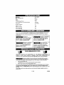
FULL ONE YEAR WARRANTY
AIR COMPRESSOR
If this air compressor fails due to a defect in material or workmanship within
one year from the date of purchase, RETURN IT TO THE NEAREST SEARS
REPAIR CENTER THROUGHOUT THE UNITED STATES AND SEARS WILL
REPAIR IT, FREE OF CHARGE. If purchased from Orchard Supply Hardware,
return to the nearest Orchard Stone and Orchard will repair it, free of charge.
]f this air compressor is used for commercial or rental purposes, the warranty
wi_lapply for ninety days from the date of purchase,
This warranfy glve_ you specific legat rights and you may ha'Je other rights
which vary from state to state.
Sears, Roebuck and Co,, Dept, 817WA, Hoffman Estates, II 60179
D26336
2-ENG
Model No.
Max. Developed HP
Bore
Stroke
919-162141
2
47-625
31.7S
Voltage-Single Phase
Minimum Br_nch Circuit Requirement
Fuse Type
120V
10 amps
Time Delay
Air Tal_k Capacity
Appro× Cutqn
Approx Cut-out
SCFM @ 40 psig
SCFM @ 90 pgi9
4
120
150
3.7
2.6
[_-Y±I.1
:t_
[_lJl.J=l_l_lm
.] =laLl_li[.]O_-']
Thls manuaL contains information that is important for you to know and understand This _nformation
rel_Ie_ t_ protecting YOUR .&&FET'f and PREVENTING EQUIPMENT PROBLI_.IvIs. To h_lp you
roco_'l;Zl! thi_: iritOrmLLtiorl. WC Ur=ethe _ymbol_ berow Please fe_ld _he m_nu_l _rlcl p3y _lention th
t h_'se
sections
F_,_1_l_lndicates
situation
result
which,
in
if not
avoided,
I_'_lIUsed
without the
safety alert symbol
indicates a potentially hazardous
situation which, if not avoided, may
result in Droner_ damaae.
_lndlcates
a potentially
f_azardous situation
which, if not avoided, _
result in
death oJ' s_rlous iniurv.
THESE
a potentially
situation
which, if not avoided, _
result in
minor or modera'ie iniurv,
will
._h_ojr_._._.
SAVE
hazardous
NS__FJUCT
ONS
_l
IMPROPER OPERATION OR MAINTENANCE OF THIS PRODUCT COULD RESULT IN
SERIOUS INJURY AND PROPERTY DAMAGE,
READ AND UNDERSTAND
ALL
WARNINGS AND OPERATING iNSTRUCTIONS BEFORE USING THIS EQUIPMEN'_,
Some dust created by power sanding, _awing, grinding, drilling, and other
construction nctivitJB_contains chemic_l_ known (to _he Slale o_ California) _o
cause c_r_ _i_ birth dB_e¢_ or other I_produc_tlv_ hsrrtl. Sore@ _(ampIe of the_e chemical_ sn9:
i_ad from _ead-base_l paints
c_/st_ll)ne _iLica [tom bricke snd cement and other rnasol_ry ptoduc_
_rsenic and chromium from chemically-treated
lumber
Your dsk Irem thesa expoaures vari_=, d_pendii_g on how often you do this type of work "re raduce
yoer e_posum _o these chomical_: w_r_ in a well v_ntilated area, _nd work with approved safety
e_qulprnor_t, =lWi=ys wear M,_I'M_/NIO_H eppr_ved, properly fitting face mask or respirator when uain_
sUCh tool&
When using air tools, basic smf_y preaaution_
p_rson_l injury.
_hould alw_y_ be followed to reduce the tisl¢ of of
3-ENG
D26_6
Save these instructions
Improper
oporatlon
or maintenance
of this product
ptop_y
damage,
Read _nd understand
using thig equipment.
II
WARNING:
could
al_ warnings
resuEt in serloua
and operation
injury
instructions
snd
before
1 2%IiD
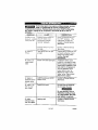
Risk of explosion
or fire
What Could Happen
How To Prevent it
It is normal for electrlcal contacts within
th_ motor _nd pressure _wlfch to spark,
Always operate the compressor _n a w_ll
ventilated area free of combustlble
rnaterlals, gasoline, or solvent vapors.
If electrical sparks from compressor
come Into €onfect with fl_mrnable
vapors, they may ignite, causing fir_ or
explosion,
It spraying flammable materi_ls, locate
€ompreesor
at least 20 feet away from
spray area. An additional length of hose
may be required.
Store flammable materials in a se;ure
location away from compressor.
Restricting
ventilation
overhearing
Never place objects against or on top
of €ompressor. Operate compressor it_
an open area at least 1:_ Inches away
from any wall or obstruction that would
restrict the flow of fre=h air to the
ventilation openings,
Operate compressor in o clean, dry waif
ventilated ar_a Do not operalle unit
indoors or in Bny confined area.
any o_ the compreE;_or
openings
w_ll cause serious
and cou)d cause fire.
Unattended operation ofthia product
could result in persona] injury or
property damage. To reduce _he rlak of
fire, do not allow th_ compressor to
operate unattended.
D?6336
Alwaye
)mduct
remain in attendance
when it is operating,
with the
Alwaya
dla¢oi_nect
electrical
powur by
moving pressure
switch I_ver to the off
)osition
and drain tank daily or after
each Use.
4- LeNG
iri_"i_iff
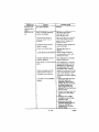
WARNING: Risk of Bursting
in a violent
1.
2.
3.
The following
conditions
could lead to a weakening
tank explosion
and could cause property
damage
of the tank, and result
or serious
injury.
What Could Happen
Failure to properly drain
condensed
water from tank.
Hqw To, Pr.even_ i_
Draln tank daily or a_ler each use, If
lank deve]aps _ leak, replace it
causing
rust and thinning
=teel tank.
immediately
with a new tank nr replace
the entire compressor.
of the
Modifications
to the tank.
or attempted
Unauthorized
modifications
repairs
to the
Never drill
modifications
into,weld, or
to the
make any
tank or its
attachments.
unloader
valve, safety va]ve, or any
other components
which control
tank
4.
pressure.
Excessive
vibration
the air tank
explosion
ATTACHMENTS
and
can
cause
The lank ]_ desigrled lo wi[hstand specific
operating pressures, Never make
adjustments or parts substitutions
to
alter the fButow sat operating
pressures.
weaken
rupture
or
& "_CCESSORI_S;
Exceeding
the pressure
rating of air
tools, 3pr_y gun_, _llr operated
=_ceseories,
tires and other inflatables
can cause them to ezplode
or fly apart,
and could
result in serious
]nJui_
For essential control of air pressure, you
must install a pressure regulator and
pressure gauge to the air outlet (if not
equipped) of your compressor. Follow the
equipment manufacturers
recommendation and never exceed the
maximum allowable pressure rating of
at'_achments. Never use _ompressor to
inflate small low pressure objects such
as children's toys, footballs,
basketballs, etc.
II
:FzY,#-,1;].•
I
WARNING: Risk from Flying Objects
WHAT CAN HAPPEN
The Gompressad air stream can _auee
soft tissue damage to exposed skin and
can propel dirt, chips, loose particles,
and smell objeGts at high speed,
resultlng in property damage or personal
Iniu_.
HOW To pREVENT IT
Alway8 Wear ANSI Z87.1 approved
safety
glaegea
with side shields when using the
Gotripf_ssor,
Never
toward
people
poJilt
any no/JEIo or sprayer
any part of the body or at other
or enirl_ale.
Always turn the compressor off end
bleed pressure from the air hose and tank
before attempting maintenance, attaching
tools or eocesaoriee.
5- ENG
D2633e
WARNING;
Risk of Burns
HOW
WHAT CAN HAPPEN
Touching e_poEed mats{ such as _hc
compressor head or outlettube_,man
result in serious burn_.
TO PREVENT
IT
Novcr touch any exposed metal par_s
on compressor
during ar immediately
after operation. Compressor
will remain
hot for saveral mlnute_ after operation,
Do not reach around proteotlve shrouds
or attempt
malntenance
until unit has
been allowed to ¢o01.
II
ir:% iP
WARNING:
Risk
from
Moving
Parts
WHAT CAN HAPPEN
HOW TO PREVENT IT
Moving parts such es the pulley, flu/wheel,
and belt can cause serious injury if they
corn into contact with you or your
_lothlng,
Never operate the ©ompr_msor with
guardo or covers which are damaged or
removed.
At(erupting
to operate
compressor
wiLh
damaged
or rniaslng parts or attempting
to repair compressor
with protective
shrouds
removed
oan e_pose you Io
moving parts and can result in serious
injuw.
Any repairs rOClLJiredon this product
should be portormed
by authorized
service
center
personnel.
III
WARNING:
E&vailil'
Risk or Serious Injury or Property Damage
When TransPorting Compressor
(Ftre, Inhatae_n,
Damage to Vehicle surfaces)
WHAT CAN HAPPEN
Oil can leak or spill and could result in
fire or breathing hazard: sedous injury or
death can result. Oil leaks will damage
carpet, paint or other surfaces in vehicles
or trailers
HOW
TO PREVFNT
IT
Always place comprQ_sor
on a
protecl_iv_
mat when transporting
to
protect against d_mage to vehicle from
leaks. Remove compressor
from vehicle
immediately
upon arrival at your
destination,
7- ENG
D28336
if2" i il'l
""' ' '111
II
WARNING: Risk Unsafe Operation
WHAT
UNsafe
operation
CAN
HAPPEN
injury
or death
[_
HOW
Of your air compressor
could Igad to serious
you or others,
to
=
TO PR_VF-NT
TT
Rcview
and understand
all Jnstruc{ians
and warnings
in this manual.
Become
familiar with the operation
and
controls
of _hc air compre,_,,r,
Keep opera_in@ are_ alger of el! persons.
pets, and ot_stacles.
Keep children away from the a_r
compressor
at all times.
Do not operate
the product when
fatigued
or under the influence
ot
alcohol
or drugs,
Stay atert at alt times.
Never defeat the safety features
of this
product.
Equip area of operation
with a flr_
cxtinguisher
Oo not oper,lte
m,_chinc with mi_ing,
broken,
or unauthorized
parts.
DZ63_
8- ENG
Become familiar
before operating
CFM:
Cubic
with these terms
the unit.
feet per minute,
SCFM:
Standard
cubic feet per
minute: a unit of measure of air
delivery.
PSIG'. Pounds per square inch
gauge; a unit of measure of pressure.
Code Certification:
Products
that
bear one or more of the following
marks; LIL, GUL, ETL, CETL, have
been evaluated
by OSHA certified
independent
safety laboratories
and
meet the applicable
Underwriters
Laboratories
Standards
for Safety.
Cut-in Pressure:
While the motor is
off, sir tank pressure
drops as you
cont[nu@ to use your accQssory.
This unit is capable
available
3rUleS
through
of powering
When the tank pressure drops to a
certain low level the motor will restart
automatically.
The low pressure at
which the motor automaticai)y
restarts is called "cut-in" pressure.
Cut*Out Pressure:
When an air
compressor
is turned on and begins
to run, air pressure in the air t_nk
begins to build.
It builds to a certain
high pressure before the motor
automatically
shuts off, protecting
your air tank from pressure higher
than its capacity.
The high pressure
at which the motor shuts off is called
"cut-out"
pressure.
Branch
Circuit:
Circuit carrying
electricity
from electrical
panel to
ou[leL
the following
the current Power
Accessories
• Tire Air Chuck
(various
Connector
The accessories
or full-line
are
Sears
• Air Pressure Regulators
• Oil Fag Lubricators
• Air Hose:l/4", 3/8" OR 1/2" I,D, in
various lengths
, in Line Filter
• Quick
Accessories.
and Hand Toot Catalog
Sets
sizes)
Refer to the selection chart located
on the unit to select the tools this unit
is capable of powering.
I;lUil'i
Air compressors
should be operated
on not more than a 50% duty cycle.
This means an air compressor
that
pumps air more than 50% of one
hour is considered
misuse, because
[_'I:-_ I =1
the air compressor is undersized for
the required air demand. Maximum
compressor pumping time per hour is
30 minutes,
S-ENG
D26336
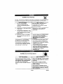
IMPORTANT.' The outlet being used
must be installed and grounded in
accordance with all local codes and
ordinances.
HOW TO SET UP YOUR
UNIT
Location
of the
Air Compressor
2.
Loce_e the air compressor
in a clean,
dry and well ventilated
area, The air
compressor
should be located at
least 12' away from the wall or other
obstructions
that will interfere with
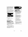
Make sure the outlet being used
has the same configuration
as
the grounded
plug DO NOT
USE AN ADAPTER.
See
illustration,
the flow of air. The air compressor
pump and shroud are designed
to
allow far proper cooling, The
Outl_t_
ventilation
openings
on the
compressor
are necessary
to
maintain proper operating
temperature,
Do not place r&gs or
other COl]t&ipers on or near these
_Groundod
/
G re tllldlrlg
31
openings
GROUNDING
INSTRUCTIONS
41
RISK OF
SHOCK.
circuit,
ELECTRICAL
In the event of a short
grounding
reduces
the rlsk
of shock by providing an escape
wire for the electric
current. This
air compressor
grounded.
Inspect the plug and cord before
each Use, Do not use if there ere
aigns of damage.
grounding
instructions
are riot completely undcrstood,
or if in doubt 4_sto whether the
compressor is properly
grounded, have the installation
checked by a qualified
electrician.
If these
IMPROPER
GROUNDING
must be properly
RESULT IN ELECTRICAL
The portable air compressor is
equipped with a cord having a
grounding wire with an appropriate
grounding plug (see following
illustrations). The plug must be used
with an outlet that has been installed
and grounded in accordance with all
local codes and ordinances,
CAN
SHOCK.
Do not modify the plug provided, If
it does not fit the available outlet, a
correct outlet should be installed
by e qualified electrician.
Repairs to the cord set or plug
MUST be made by a qualified
electrician.
The cord set and plug with this
unit containa a grounding pin.
This plug MUST be used with a
grounded outlet.
D26336
PIll
10- ENG
E:_te_lsion
Cords
Using extension
recommended.
cords
Voltage
will cause
voltage
Protection
Refer to the Specification Chart for
the voltage and minimum branch
circuit requirements.
cords is not
The use of extension
resulting in power
ang overheating.
a[_d Circuii;
to drop
loss to the motor
Certain
Attacn extra air hoses at tt/e air outlet
instead of us)rig extension
cords.
operated
following
airoompressor_
can be
on a 15 amp circuit
conditions
are met.
if the
1.
Voltage supply through branch
circuit is 15 crops.
2.
a 3-blade grounding
plug, and a
3-stot receptacle
that will accept
the plug on the product
Circuit is not used to supply any
other electrical needs (lights,
appliances, etc.).
3.
E".xtertsion cords comply with
speciticatlons.
In good
4.
Circuit is equipped with a 15
amp circuit breaker or 15 amp
tinle delay ruse. NOTE: tf
compressor is connected to a
circuit protected by fuses, u_e
only time delay fuses. Time delay
fuses should be marked "D" in
Canada and "T" in the US
If ar_ extension
sure it is;
a 3-wire
no longer
cord
must
extension
be used,
cord
be
that has
condition
than
50 feet
12 gauge (AWG) or Jarger. (WJr_
_lze Jncrsases as gauge number
decreases.
10 AWG and 8 AWG
may also be used,
14 OR 16AWG)
DO NOT USE
If any of the above conditions cannot
be met, or if operation of the
compressor repeatedly causes
interruption of the power, it may be
necessary to operate it from a 20
amp circuit. It is not necessary to
change the cord set.
1t - ENG
D26336
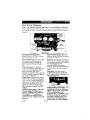
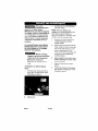
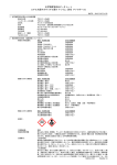
Know Your Air Compressor
READ THiS OWNER'S MANUAL AND SAFETY RULES BEFORE OPERATING
YOUR UNIT. Compare the illustrations with your unit to familiarize yourself with
the location of various controls and adjustments. Save this manual for future
reference.
' Regulator
8_e_t
Description
of Operation
Become familiar wlth these controls
before operating th_ uniL
On/Auto/off
Switch; Turn this switch
ON to provide automatic power to
the pressure switch and OFF to
remove power at the end of each
use.
Pressure Switch: The pressure
switch automatically starts the motor
when the air tank pressure drops
below the factory set "cutqn"
pressure. It stops the motor when the
air tank pressure reaches the factory
set "cut-out" pressure,
Safety Valve: If the pressure switch
does not shut off the air compressor
at its "out-out" pressure setting, the
safety vane will protect aga}nst high
pressure by "popping out" at its
factory set pressure (slightly higher
than the pressure switch "eut-o,,t*
setting).
Outlet Pressure Gauge; The outlet
pressure gauge indicates the air
_>¢essureavaUable at the outlet side
of the regulator. This pressure is
controlled by the regulator and is
always less than or equal to the tank
pressure
D20336
Valve
Tank Pressure
Gauge:
The tank
pressure gauge indicates the reserve
air pressure in the tank.
Regulator:
Controls
the _ir 13rossurQ
shown on the outlet pressure gauge,
Pull the knob out and turn clockwise
to increase pressure and
counterclockwise
to decrease
pressure. When the desired pressure
Is reached push knob in to lock in
place.
Drain Valve.' The drain valve is
located at the base of the air tank
and is u_ed to drain condensation
at
the end of each use,
Cooling System (net shown): This
compressor contains an advanced
design cooling system. At the heart
of this cooling system is an
engineered fan. It is perfectly normal
for this fan to blew air through the
vent holes in large amounts. You
know that the cooling system is
working when air Is being expelled.
12- ENG
Air Compressor
Pump (not shown);
Compresses
air into the air tank.
Working air Je not avaiJable until the
compressor
has raised the air tank
pressure above that required at the
air outlet.
Check
Valve:
When
the air
comDressor
is operating,
valve is "open", allowing
air to enter the sir tank
the cheek
compressed
When the air
compressor
reaches "cut-out"
pressure, the check valve "closes",
allowing air pressure re remain inside
the sir tank.
On/Au[o/
Off Leve
2,
Plug the power cord into the
correct branch cimuit receptacle.
(Refer to Voltage and Circuit
Protectlon paragraph inthe
Installation section of this
manual.)
3,
Open file drann v_lvo iully
(counterclockwise) to permit air
toescape and prevent air
pressure build up in the air tank
during the break-in period.
4.
Move
How to Use Your Unit
How to Stop:
1.
Set the On/Auto/Off
"OFF".
Before
First
Break-in
]ever to
1
Make
sure the On/Aut0!Off
NOTE:
Pull coupler
to prevent air from
the quick connect.
compressor
will start.
lever to
The
Run the compressor for 15
minutes. Make sure the drain
valve is open a,nd there is
minima] air pressure build-up in
tank,
6,
After 15 minutes, close the drain
valve (clockwise). The air receiver
will fill to "cut-out" pressure and
the motor will stop,
Procedure
is in the "OFF"
posi[iorl
5,
Start-up
Serious damage
may result if the
following break-in instructions
are
not closely followed,
Thisprocedure is required before the
air compressor Is put into service and
when the check valve or a complete
compressor pump has been
replaced
the OnlALrto/Ofl
"ONIAUTO"
The compressor is now ready for use.
lever
position.
back
untiP it c_icks
escaping
through
13-ENQ
D28336
Befo]e
Each
}-low to Start:
Start-Up:
I.
Place On/Auto/Off lever to
"OFF" end close air regulator.
2.
Pull regulator knob out, turn
counterclockwise
until it stops.
3
Attach hose and accessories.
NOTE: The hose or accessory
will reuu_re e quick connect plug
if the air outlet is equipped with a
quick connect socket.
Push
1.
knob in to lock in place.
2,
Turn the On/Auto/Off lever to
"AUTO" and allow tank pressure
to build, Motor will stop when
tank pressure reaches "cut-out"
pressure.
Pull the regulator knob out and
turn clockwise
to increase
pressure.
Whet_ the desired
pressure is reached push knob in
to lock in place, The compressor
is ready for use.
I_1_
Too much air
pressure causes a
hazardous risk of bursting. Check
the manufacturer's
maximum
pressure rating for air tools and
accessories, The regulator outlet
pressure must never exceed the
maximum pressure rating.
D_6336
NOTE; Always operate the air
compressor in well-ventilated areas
free of gasoline or olher combustible
vapors, If the compressor isbeing
used to op_rate a sprayer DO NQT
place near the sprayarea.
14- ENG
Customer
Responsibilities
_eforo
_ach
J@@
Daily or
after
each
U_O
]hack Safety Valve
•
3rain Tank
Unit cycles
automatically
when
power is on. When performing
maintenance,
you may be exposed
to voltage sources, compressed
air, or moving
parts. Personal
injuries
can occur. Before
performing
any maintenance
or
repair, disconnect
power
source
from the 6ompr_ssor
and bleed off
all air pressure.
To Drain
Set the On/Auto/Off
"OFF".
2.
Putt the regulator knob out and
turn clockwise to set the outlet
pressure to zero.
3.
Remove the air tool or
Safety Valve
If the safety valve
does not work
properly, over-pressurization may
occur, causing air tank rupture or
an explosion,
1. Before starting compressor, pu]!
the ring on the safety valve to
make sure that the safety valve
operates freely If the valve is
stuck or does not operate
smoothly, it must be replaced
with the same type of valve.
lever to
accessory.
4
Pull ring on safety valve allowing
air to bleed from the tank until
tank pressure is approximately
20 psi. Release safety valve dng.
5.
Drain water tro133 air tank by
opening drain valve (caunter-
NOTE: See "Operation" section for
the location of controls.
To Check
Tank
1.
clockwise)
on bottom
of tank.
Water will
condense
in the air
tank. If not drained, water will
corrode and weaken the air tank
causing
6.
a risk of air tank
rupture,
After the water has been drained,
close the drain valve (clockwise),
The air compressor can now be
stored.
NOTE: If drain valve is plugged,
release all air pressure, The valve
can then be removed, cleaned, the
reinstalled
15- ENG
026336
power
Unit cycles
nutomatjcally
Is on, When doing
Maintenance,
3.
when
you may be exposed
to voltage sources, compreased
air
or moving parts, Personal injuries
can occur. Before peHorming
any
Maintenance
or repair, unplug the
compressor
and bleed off all air
NOTE; The hose clamp is not
reusable. You must purchase a new
hose clamp, see the Parts List
Manual or purchase a standard hose
clamp at a Iota[ hardware store,
4,
pressure.
ALL MAINTENANCE AND REPAIR
OPERATIONS NOT LISTED MUST
BE PERFORMED BY A TRAINED
SERVICE[ TECHNICIAN.
Before
Bleed
tank
Allow
cool
the air compressor
To Replace
Valve
1.
2.
6.
ot pressure
or Clean
Apply seelsnt to the check valve
threads,
Reinstall the check valve
/turn clockwTse).
to
7.
Replace hose and new hose
clamp.
8.
Perform th_ Breakqn Procedure,
See "Break-ln
Procedure" In the
Check
Release all air pressure from air
tank. S_e "To Drain Tank" in the
Maintenance section.
Unpiug unit.
D2533S
Unscrew the check vatve (turn
counter-clockwise) using a
socket wrench.
Make sure the valve disc moves
freely inside the check valve and
the spring holds the disc in the
upper, closed position The
check valve may be cleaned with
a solvent, such as paint and
varnish removsL
servicing:
Unplug or disconnect
electrical
supply
to the air compressor.
Remove the hose by removing
the hose clamp.
rS- ENG
Operat{on
section.
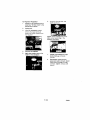
To Replace Regulator
1. Release all air pressure from air
tank. See "To Drain Tank' inthe
Maintenance section.
2
Unplug
3,
Using an adjustable
wrench
remove the outlet pressure
gauge and quick connect from
the regulator
6, Assemble the regulator and
orient as shown.
unit.
NOTE:
Arrow
indicates
Make sure it is pointing
direction of air flow.
4.
Remove the regulator.
5.
App{y pipe sealant tape to the
nipple on the standpipe.
flow of air,
in the
7.
Reapply pipe sealant to outlet
pressure geuge and quick
connect.
8.
Reassemble
outlet
pressure
gauge and quick connect. Orient
outlet pressure gauge to read
correctly, Tighten connect with
wrench,
17- ENG
D2633S
Before
make
1.
you store the air compressor,
Review
tank.
If not drained,
corrode and weaken
the "Maintenance"
section on the preceding
and perform
scheduled
ma}ntenence
2
Water will
condense
in the air
sure you do the following:
pages
causing
7.
as necessary,
Bet the On/Auto/Off
lever to
"OFF".
3
Turn the regulator
counterolockwiae and set the
outlet pressure to zero.
4.
Remove
the air tool
or
8.
Pull ring on safety valve allowing
air to bleed from the tank until
tank pressure is approximately
20 psi. Release safety valve ring.
Drain water from air tank by
opening drain valve on bottom
tank.
D2633S
a risk of air tank
rupture.
After the water has been drained,
close the drain or drain valve.
NOTE: If drain valve is plugged,
release all air pressure. The valve
can then be removed, cleaned, then
reinstalled.
accesso_.
6
water will
the air tank
of
18-ENG
Protect t_e electrical cord and air
hose from damage (such as
being stepped on or run over).
Wind them loosely around tile
compressor handle. (if so
equipped)
Store the air compressor in a clean
and dry location.
II
Performing repairs may expose voltage sources, moving
parts or compressed air sources, moving parts or
compressed air sources. Personal inju W may occur. Prior to attempting
any repairs, unplug the air compressor and bleed off all air tank air
pressure.
PROBLEM
CAUSE
Excessive t_}lk
Pressure
pressbre safet
valve pops off
shut of1 motor
compressor
"cut-out"
Air leaks
at
fittin@s,
switch
CORRECTION
Ooes not
when
reaches
pressure.
Move On/Auto/Off
levor to
the "OFF" position,
if the
outfit does not shut off
contact s Trained Service
Technician.
Pressure switch "cut-out"
too high.
Contact a Trained Service
Techniciam
Tube fittings are not tight
enough.
Tighten fittings where air sen
be heard escaping, Check
fittings with soapy water
solution. Do Not
Overti@hten,
A defective check valve
results in a constant air leak
st the pressure release valve
when there is pressure in the
tank and the compressor is
shut off, Replace check
valve. Refer to the "To
Replace or Clean Check
Valve" in the "Service and
Adjustment" section.
Air leaks at or
insicte check
va!ve
Cheek valve seat damaged.
Air leaks
Defective pressure switch
release valve.
Contact a Trained Service
Technician.
Defective air tank.
Air tank must be replaced,
Do not repair the leak.
at
pressure switch
release valve
Air leaks in air
tank or at air
tank welds,
Do not drill into, weld or
otherwise modify air tank
or it will weaken, "fhe tank
can rupture or explode.
Air leaks
between head
and valve plate.
Leaking seal.
Contact a Trained SerVice
Technician.
1 @- ENG
D28336
CORRECTION
CAUSE
PROBLEM
Regulator
will
not shut off air
Damaged regulator.
Replace.
Motor overload protection
switch has tripped.
Let motor cool off and
overload switch will
automatically reset.
Tank pressure exceeds
_ressure switch "cut-in"
Motor wilr start automatically
when tank pressure drops
below "cut-in"
pressure of
)ressure switch.
outlet.
Motor
run,
will not
pressure.
Extension cord le wrong
length or gauge.
Cheek
Ct_eck vane stuck open.
Remove
for proper
and cord
gauge
wire
length.
and clean,
or
replace.
Loose
electrical
Possible
starting
detective
unloaded
Check wiring connection
inside pressure switch and
terminal box area,
motor
Have checked
by a "ira ned
Service Technician.
or
capacitor.
Paint spray
_arte.
Pressure
)resaure
cennection_
on internal
motor
release valve on
switch has not
head pressure.
Fuse blown, circuit breaker
tripped.
21-ENG
Have checked by a Trained
Se_ice Technician, Oonot
operate the compressor in
the paint spray area. See
flammable vapor warning.
Bleed the line by pushing the
lever on the pressure switch
to the "off" position; if the
valve does not open, replace
switch.
1. Cheek fuse box for blown
fuse end replace as
necessary. Reset circuit
breaker. Do not use a fuse
or circuit breaker with
higher rating than that
specified for your particular
branch circuit.
2. Check for proper'fuse. You
should use a time delay
fuse.
3. Check for low voltage
conditions and/or proper
extension con:[.
4. Disconnect the other
electrical appliancea from
oimult Or operate the
compressor on its own
branch circuit.
D_6336
Air Compressor
D2@336
Model
Number
919.152141
22-SP
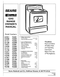
Air Compressor
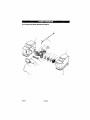
Model Number 919.152141
KEY
NO_
1
PART NUJVIBER
Z-D24671
3
91895680
4
5
SSF-621
SSP-480
6
7
SSW-7480
AC-0430
SS_5314-1
8
D20114
9
D20643
10
D20675
11
12
Z-D2185_
$8-2071
13
SSW-7367
14
SSP-6021
15
17
Z-D25879
$$P-537
18
D28878
19
20
CAC_1254
+
21
CAC-1206-1
24
26
LA-3092-!
SUDL-403-1
28
LA-3108
33
D24204
34
D21921
+ order Indivicluaf
parts, see pump
D.ESCRIPTION
Tank
Recess Rubber Bumper (3 used)
Screw (3 used)
Screw (2 used)
Nipple, 1/4-18 NPT X 2.50
Strain Relief Bushing
Drain Valve
Safety Valve
Regulator
Quick Connect 1/4 NPT
Gauge 2" (2 used)
Nipple, 1/4-18 NPTX 1.5
Strain Relief Bushing
Bushing Reducer 1/8-1/4NPT
Pressure Switch
Fitting, 90 ° Elbow Hose
Check Valve
Pump Isolator (4 used)
Pump Assembly
Hose Clamp
Label, Drain Tank Eng/Spa
Cord Assembly
Label, Hot Surface
Label, Sears Performance
Label, Star Rating #3
diagram
23- ENG
D26338
•.Jil
ivj
I:JlD]V±T_:__,I
_,_
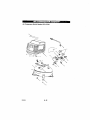
Air Comprassor Model Number 919.152141
2
026336
24-ENG
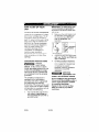
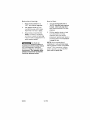
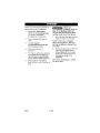
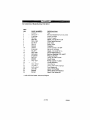
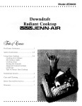
Air Compressor
Model
Number
919,152141
KEY
N_%,
2
3
4
5
6
7
8
9
10
11
12
13
14
15
17
18
19
20
21
Ng&_RLEUmg_
T
>
x
>
CAC-1320
D25735
D25877
CAC -1212
D22253
CAC-J 199
Z_CAC-4323
SSG-8169
.........
SSF-3147
Shroud (felt)
Shroud (right)
Head
Tube Seal
Outtet Tube
Head Gasket
Valve Plate Assembly
O-Ring 2.132/2,0961D ,073/.067W
Cylinder $_seve
Screw, 3/8-16UNC Socket Head
Rod Assembly
Endbelf Assembly
Screw, 8-32X.375/.344
Pump Isolator (5 used)
Washer Screws 10-24 x 7/8 (4 used)
Motor Corfi
Hess Clamp
Hose, I/4"ID X lO"Length
Screw, lo-9X.50 P(astite (5 used)
Motor Brush Replacement
Z-[923584
SUDL-9-1
025731
x
88F-995
D81659
CAC-1206-1
H-7051
x
SSF-3156
............
x
x
>
NotIllu_ s_rated
LA-3270
D26335
Label, Warning Eng/Span
Operators Manual
K-0387
KK-4929
KK-4964
Isolator Kit
Fastener Kit
Gonnecting Rod Kit
Motor number Is stamped on motor suck, sos for
correct motor.
Motor
M0-9088
D23494
uses
uses
Brush
Z-D20041
Z-D23825
2S-ENG
D26336