1
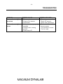
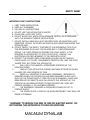
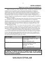
Magnum Dynalab MD 308
INTEGRATED AMPLIFIER
INSTRUCTION MANUAL
-2-
TABLE OF CONTENTS
A MESSAGE FROM THE PRESIDENT
3
UNPACKING YOUR MD 308
4
SETTING UP THE MD 308
5
CONNECTING SPEAKERS AND POWERING THE MD 308
5
HOOKING UP SOURCES TO THE MD 308
6
SET UP THE MD 308 WITH AN EXTERNAL HOME THEATER PROCESSOR
6
HOOKING UP A SUBWOOFER TO YOUR SYSTEM
7
TAPE OUT LOOP
7
POWER VU-METERS
7
CONTROL & DISPLAY FUNCTIONS
8
REMOTE CONTROL
9
FUNCTIONS OF THE REMOTE
9
TROUBLESHOOTING
10
SAFETY SHEET11
LIMITED WARRANTY
12
-3-
A Message From the President
Thank you for choosing the Magnum Dynalab MD 308 Integrated Amplifier. Great
care has been given in the design, manufacturing and selection of components for
the MD 308 Integrated Amplifier. This complete process insures optimum listening
enjoyment for many years.
Simplicity of the circuit using high grade components insures that accuracy and
realism of the music is the end result. The power supply with its specially designed
transformer is at the heart of the stability and dynamics that the MD 308 exhibits.
When using these high grade components a considerable length of time is required
for the MD 308 to reach its full potential, either a high quality break in disc or white
noise from a FM tuner will insure optimum performance.
Once again thank you for including a MAGNUM DYNALAB product in your
entertainment system, we are sure that you will have years of listening pleasure
from your MD 308. If there is anything else we can do, please call us on our toll
free number, 1-800-551-4130 or contact us via email at:
[email protected].
Respectfully yours,
Larry Zurowski
President
-4-
UNPACKING YOUR MD 308
Carefully inspect all sides of the shipping carton for damage. If there are marks or
holes in the carton make note of the location in relation to the unit inside. Any
obvious dents or scuff marks should alert you to the possibility of damage. Carefully
remove the MD 308 from the end caps and wrapping, inspect all sides. Pay special
attention to the corresponding areas on the unit where damage was found to the
shipping carton. If damage is evident, document the type and extent of the damage,
then repack the unit and call the dealer.
KINDLY DO NOT SEND THE UNIT BACK TO THE SHIPPER UNTIL YOU HAVE BEEN
ASKED TO DO SO.
DO NOT DISCARD THE PACKING MATERIALS AND CARTONS. Should there be a
necessity to return the unit for any reason, it must arrive safely and suitably
packaged in order for our receiver to accept it from the carrier. Also, if the unit has
incurred damage as a result of improper packaging, it is not likely that a claim for
the damage against the carrier will be successful.
Likewise, we will ship your unit back to you only in factory-approved packaging,
However, if the unit were to arrive at the factory in anything other than factory
approved packaging, we reserve the right to return same in factory-approved
packaging and charge the cost of the packaging to the shipper. This is the only way
we can assure you of a safe return (damage by carrier excepted).
-5-
SETTING UP THE MD 308
1. Position the receiver away from any spot which may have extremes in
temperatures.
2. Place the receiver on a very rigid surface capable of holding 50 pounds (22 KG).
3. The heat sinks on the side of the unit are used to keep the unit at a safe
operating temperature. It is important that they are not covered or the unit is not
installed in a closed area where there is little air circulation. Ensure at least 2” of
clearance on the left and right of the device, and 5” of clearance above the unit
to allow for proper ventilation. Further, keeping the heat sinks clean will maintain
the high level of efficiency for which they were designed. A soft cloth or
paintbrush works just fine to keep them clean.
4. Unwrap the EIA AC cord and plug the EIA end into the rear socket marked Power
Input. Plug the other end of the AC cord into a 120/220/230/240 volt
continuous AC power supply. Be sure that the voltage marked on the rear of the
unit is the same as the AC source that you are using.
CONNECTING SPEAKERS AND POWERING THE MD 308
1. Now that you have unpacked and positioned the MD 308 you are ready to hook it
up. Hook up your speakers to the receiver insuring that the positive (+) terminal
on the speaker is hooked up to the positive (+) output terminal on the receiver,
likewise that the negative (-) is correctly hooked up. Be sure that all the
connections are tight.
2. Located on the rear of the unit is a switch (directly beside the AC cord input).
Turn it “ON” by depressing the top of the switch.
3. Turn the power switch “ON”; the LED above the power switch should be on. The
center display will light up indicating which source is on.
-6-
HOOKING UP SOURCES TO THE MD 308
1. Using your RCA cables, plug the other source into one of the inputs marked in
the back of the MD 308.
2. Set the input on the receiver to match the input on the rear of the unit that the
other source is plugged into.
3. With volume set to zero, power up the new source, initialize the playback, and
slowly adjust volume to desired level.
CAUTION
As standard practice, you should always turn off the main power to the MD 308
(found on the rear panel of the MD 308), whenever any source component,
interconnect or loudspeaker is being changed in your system.
Be aware, when activating Home Theater mode on input A4, the volume level on
input A4 will be wide open. Please make sure that the RED LED above the input
button is not lit if a regular source is connected to input A4.
SET UP THE MD 308 WITH AN EXTERNAL HOME THEATER
PROCESSOR
The MD 308 is equipped with a unity gain input (A4 Input on the Pre-Amplifier
section). This is a switchable input, meaning the input can be used as a normal preamplifier input or in unity gain mode.
To Connect to a Home Theater Processor
1. Turn the power off to the MD 308 by the main power switch on the rear of the
unit.
2. Connect your theater processor Main Left and Right interconnects into the MD
308 through the A4 input.
3. Connect your Main Left and Right speakers to the MD 308 speaker connections.
4. Power up the MD 308 by switching the main power rocker switch found on the
rear of the MD 308, to the “ON” position.
5. Press and HOLD the “Input” button (found on the faceplate of the MD 308) for at
least 3 seconds. A red LED above the input button will light, and this indicates
that the theater mode of input A4 is now active.
-7-
6. Input A4 is now the dedicated input for you to listen and control volume with your
home theater processor (Meaning that when you listen to regular music you use
the preamplifier found in the MD 308). Once input A4 has been activated into
Home Theater mode, volume on input A4 will now be controlled via your external
processor preamp.
HOOKING UP A SUBWOOFER TO YOUR SYSTEM
1. Make sure your receiver is turned “OFF”.
2. Using RCA cables, connect one end to the Pre Out input marked on the rear of
the Receiver, the other end to your subwoofer.
3. Turn the subwoofer “ON”.
4. Turn the receiver on and adjust the volume level to suit you.
Please note the volume of the subwoofer is controlled by the volume control on the
receiver.
TAPE OUT LOOP
This is used if you wish to record the music you are listening to. Connect this to a
recordable peripheral source.
POWER VU-METERS
The MD 308 has been equipped with special power output meters. These meters
reflect the power output of the amplifier during music playback.
The MD 308 is capable of momentary power demands of well over 250 watts,
without “clipping”, or running out of power. The meters have a red area at the right
hand side, during normal music playback, certain passages of music will bring you
frequently into the red zone. This normal occurrence is a direct result of musical
peaks, and it is not an indication of the amplifier having reached its maximum power
output.
If meters remain in red area for periods exceeding 10 seconds, this indicates that
the amplifier is reaching its maximum power output level – reduce volume
-8-
CONTROL & DISPLAY FUNCTIONS
1. LEFT BALANCE INDICATOR: This will light up when you change the output balance
of the amplifier. Note that the amount of deviation from center balance will be
shown in dB on the display.
2. INPUT INDICATOR: When the MD 308 is powered on, this LED will be lit.
3. RIGHT BALANCE INDICATOR: This will light up when you change the output
balance of the amplifier. Note that the amount of deviation from center balance
will be shown in dB on the display.
4. POWER SWITCH: Turns the MD 308 ON, showcased by the lit red LED above
the knob.
5. POWER METER: The right channel power output watt meter indicates the power
output of the right channel, the left channel power output watt meter indicates
the power output of the left channel. Please read the info on Power VU – meters.
6. INPUT/VOLUME: When adjusting the volume either with the remote or manual
knob, a number from 0-50 will appear in this display. When changing the input
source, the source chosen will be shown in the display.
7. VOLUME CONTROL: The volume can be controlled manually or via the remote
control.
-9-
RC8 REMOTE CONTROL
Unpacking the Remote:
• Remove the remote from its plastic bag, and install the 3 AA batteries provided
• Test the remote to make sure that all functions are operating correctly.
FUNCTIONS OF THE REMOTE
Please note that the RC8 remote includes certain features which are not active on
the MD-308. The remote has been designed to be compatible not only with the MD308, but also with our collection of analog FM tuners. Therefore, this remote will be
functional with a Magnum Dynalab tuner should one be added to your home audio
system.
Only active functions of the RC8 remote are listed below.
1. POWER MAIN: Power ON & OFF
2. VOLUME UP/VOLUME DOWN: Reduces or increases the volume output level of
the preamplifier section of the MD 308.
3. BALANCE LEFT/BALANCE RIGHT: Increases the relative output of the selected
speaker (left/right) compared to the other speaker.
4. INPUT: Adjusts the selected source received by the preamplifier section of the
receiver (i.e. Tuner, CD, Aux 1).
5. AUDIO MUTE: Mutes the amplifier section of the receiver.
- 10 -
TROUBLESHOOTING
PROBLEM
No sound, meter lights
are not on
No sound, meter lights
are on
POSSIBLE CAUSE
• Power cord disconnected
• Power off at source
• Fuse blown
• Interconnect not properly
installed
• Preamp set to wrong
source
• Power amp off
POSSIBLE SOLUTION
• Connect power cord
• Check AC source
• Check rear panel fuse
• Check installation of
interconnects
• Turn preamp to tuner
• Turn on amp
- 11 -
SAFETY SHEET
IMPORTANT SAFETY INSTRUCTIONS
1.
2.
3.
4.
5.
6.
KEEP THESE INSTRUCTIONS
HEED ALL WARNINGS
FOLLOW ALL INSTRUCTIONS
DO NOT USE THIS APPARATUS IN WATER
CLEAN ONLY WITH DRY CLOTH
DO NOT BLOCK ANY VENTILATION OPENINGS, INSTALL IN ACCORDANCE
WITH THE MANUFACTURER’S INSTRUCTIONS.
7. DO NOT INSTALL NEAR ANY HEAT SOURCES SUCH AS RADIATORS, HEAT
REGISTERS, STOVES, OR OTHER APPARATUS (INCLUDING AMPLIFIERS) THAT
PRODUCE HEAT.
8. DO NOT DEFEAT THE SAFETY PURPOSE OF THE GROUNDING TYPE PLUG.
THE GROUNDING PLUG HAS TWO BLADES AND A THIRD GROUNDING
PRONG. THE THIRD PRONG IS PROVIDED FOR YOUR SAFETY. IF THE
PROVIDED PLUG DOES NOT FIT INTO YOUR OUTLET, CONSULT AN
ELECTRICIAN FOR REPLACEMENT OF THE OBSOLETE OUTLET.
9. PROTECT THE POWER CORD FROM BEING WALKED ON OR PINCHED
PARTICULARLY AT PLUGS, CONVENIENCE RECEPTACLES, AND THE POINT
WHERE THEY EXIT FROM THE APPARATUS.
10.
ONLY USE ATTACHMENTS/ACCESSORIES SPECIFIED BY THE
MANUFACTURER.
11.
UNPLUG THIS APPARATUS DURING LIGHTNING STORMS OR WHEN
UNUSED FOR LONG PERIODS OF TIME.
12.
REFER ALL SERVICING TO QUALIFIED PERSONNEL. SERVICING IS
REQUIRED WHEN THE APPARATUS HAS BEEN DAMAGED IN ANY WAY,
SUCH AS THE POWER SUPPLY CORD OR PLUG IS DAMAGED, LIQUID HAS
BEEN SPILLED OR OBJECTS HAVE FALLEN INTO THE APPARATUS, THE
APPARATUS HAS BEEN EXPOSED TO RAIN OR MOISTURE, DOES NOT
OPERATE NORMALLY, OR HAS BEEN DROPPED.
13.
THE EQUIPMENT REQUIRES A GROUNDED POWER OUTLET TO
OPERATE SAFELY.
14.
THE POWER SUPPLY CORD IS THE MAIN DISCONNECT AND SHALL BE
READILY OPERABLE.
“WARNING” TO REDUCE THE RISK OF FIRE OR ELECTRIC SHOCK, DO
NOT EXPOSE THIS APPARATUS TO RAIN OR MOISTURE.
- 12 -
LIMITED WARRANTY
Register your product at www.magnumdynalab.com
Magnum Dynalab Ltd. herein referred to as the “manufacturer” guarantees this
product to be free of defect in both material and workmanship and agrees to
remedy any such defect or replace any defective component at no charge for a
period of two years from date of sale to the first end user. This warranty is void if
the product has been found to be subjected to misuse, abuse, lightning strike,
unauthorized service, damaged in transit or has been altered or repaired in such a
way as to detract from its performance, reliability or its safe operation. All tubes are
covered for 12 months.
Should such defect be discovered and it falls within the terms of this guarantee,
the manufacturer will correct the defect in workmanship and/or replace any
defective component with a new one of similar capability and value. This warranty
does not apply to the cabinet or appearance items such as the faceplate, control
knobs or meter lenses nor does it cover any expenses in shipping the unit to the
appropriate service depot.
The foregoing is in lieu of any other warranties expressed, implied or statutory
and the manufacturer neither assumes nor authorizes any person to assume for it
any other obligation or liability in the connection with the sale of this product. This
warranty is not transferable except by written authorization from the manufacturer.
In order to qualify under the terms of the above warranty, all items must be
returned to the appropriate factory service depot with all shipping charges prepaid
in lieu of having previously registered the purchase of the unit by completing and
returning the attached Registration Card, the unit must be accompanied by proof
from an authorized Magnum Dynalab Ltd. dealer.
YOUR LOCATION
Within the USA
Within Canada
Other Countries
RETURN SHIPPING ADDRESS
Magnum Dynalab c/o Trans American
2775 Broadway, Buffalo, NY, USA
14227-1043
PHONE: 1-800-551-4130
Magnum Dynalab Ltd.
8 Strathearn Avenue, Unit # 9
Brampton, ON, Canada
L6T 4L9
PHONE: 1-800-551-4130
Contact selling dealer
TO PREVENT FIRE SHOCK OR HAZARD, DO NOT EXPOSE THIS APPLIANCE TO RAIN
OR MOISTURE. TO REDUCE THE RISK OF ELECTRIC SHOCK, DO NOT REMOVE
COVER OR FACEPLATE, NO USER SERVICEABLE PARTS INSIDE. REFER SERVICING
TO QUALIFIED SERVICE PERSONNEL.